sara plus - medicaleshop inc.cdn.medicaleshop.com/media/pdfs/arjohuntleigh/sara-plus-standing... ·...
TRANSCRIPT
SARA PLUSINSTRUCTIONS FOR USE
...with people in mind
0086
1
Contents
Safety Instructions . . . . . . . . . . . . . . . . . . . . . . . . . . . . . . . . . . . . . . . . 3
Foreword . . . . . . . . . . . . . . . . . . . . . . . . . . . . . . . . . . . . . . . . . . . . . . . . 4Consumables . . . . . . . . . . . . . . . . . . . . . . . . . . . . . . . . . . . . . . . . . . . . . . . . . . .4
Product Description/Function . . . . . . . . . . . . . . . . . . . . . . . . . . . . . . . 5Intended Use . . . . . . . . . . . . . . . . . . . . . . . . . . . . . . . . . . . . . . . . . . . . . . . . . . .5Parts referred to in this manual . . . . . . . . . . . . . . . . . . . . . . . . . . . . . . . . . . . . . .6Controls and Features . . . . . . . . . . . . . . . . . . . . . . . . . . . . . . . . . . . . . . . . . . . .7Control handset . . . . . . . . . . . . . . . . . . . . . . . . . . . . . . . . . . . . . . . . . . . . . . . . .7Dual control panel . . . . . . . . . . . . . . . . . . . . . . . . . . . . . . . . . . . . . . . . . . . . . . .7Emergency stop button (red) . . . . . . . . . . . . . . . . . . . . . . . . . . . . . . . . . . . . . .7Power on/Reset button (green) . . . . . . . . . . . . . . . . . . . . . . . . . . . . . . . . . . . . .8Power off button (red) . . . . . . . . . . . . . . . . . . . . . . . . . . . . . . . . . . . . . . . . . . . .8Automatic cut out . . . . . . . . . . . . . . . . . . . . . . . . . . . . . . . . . . . . . . . . . . . . . . .8Automatic stop function . . . . . . . . . . . . . . . . . . . . . . . . . . . . . . . . . . . . . . . . . . .8System failure lower override . . . . . . . . . . . . . . . . . . . . . . . . . . . . . . . . . . . . . .8Battery Discharge Indicator . . . . . . . . . . . . . . . . . . . . . . . . . . . . . . . . . . . . . . . .8Hour Meter . . . . . . . . . . . . . . . . . . . . . . . . . . . . . . . . . . . . . . . . . . . . . . . . . . . .8Chassis castor Brakes . . . . . . . . . . . . . . . . . . . . . . . . . . . . . . . . . . . . . . . . . . .8Straight line steering function . . . . . . . . . . . . . . . . . . . . . . . . . . . . . . . . . . . . . .8Arc-Rest (with handgrips) . . . . . . . . . . . . . . . . . . . . . . . . . . . . . . . . . . . . . . . . .9Foot Support . . . . . . . . . . . . . . . . . . . . . . . . . . . . . . . . . . . . . . . . . . . . . . . . . . .9Proactive Pad™ . . . . . . . . . . . . . . . . . . . . . . . . . . . . . . . . . . . . . . . . . . . . . . . .9Lower leg Straps . . . . . . . . . . . . . . . . . . . . . . . . . . . . . . . . . . . . . . . . . . . . . . . .9Adjustable width chassis legs . . . . . . . . . . . . . . . . . . . . . . . . . . . . . . . . . . . . . .9
Commode Seat (Accessory) . . . . . . . . . . . . . . . . . . . . . . . . . . . . . . . . . . . . . . .10Using the Sara Plus for Toiletting and Transporting . . . . . . . . . . . . . . . . . . . . .11
Using your Sara Plus . . . . . . . . . . . . . . . . . . . . . . . . . . . . . . . . . . . . . 11Standing Sling . . . . . . . . . . . . . . . . . . . . . . . . . . . . . . . . . . . . . . . . . . . . . . . . . .12Transfer and Walking Sling . . . . . . . . . . . . . . . . . . . . . . . . . . . . . . . . . . . . . . . .14ArjoHuntleigh Scale (if fitted) . . . . . . . . . . . . . . . . . . . . . . . . . . . . . . . . . . . . . .20Scale Labels . . . . . . . . . . . . . . . . . . . . . . . . . . . . . . . . . . . . . . . . . . . . . . . . . . .20Scale Display . . . . . . . . . . . . . . . . . . . . . . . . . . . . . . . . . . . . . . . . . . . . . . . . . .21Display symbols /functions . . . . . . . . . . . . . . . . . . . . . . . . . . . . . . . . . . . . . . . .21Method “A” Weighing before the patient is suspended in the sling. . . . . . . . . .22Method “B” Weighing with the patient already suspended in the sling. . . . . . .22Calibration . . . . . . . . . . . . . . . . . . . . . . . . . . . . . . . . . . . . . . . . . . . . . . . . . . . . .23
Care of your Sara Plus . . . . . . . . . . . . . . . . . . . . . . . . . . . . . . . . . . . . 26General Lifter Care . . . . . . . . . . . . . . . . . . . . . . . . . . . . . . . . . . . . . . . . . . . . . .26Environmental Advice . . . . . . . . . . . . . . . . . . . . . . . . . . . . . . . . . . . . . . . . . . . .27Periodic Testing . . . . . . . . . . . . . . . . . . . . . . . . . . . . . . . . . . . . . . . . . . . . . . . .27Emergency Stop . . . . . . . . . . . . . . . . . . . . . . . . . . . . . . . . . . . . . . . . . . . . . . .27Adjustable Width Chassis Function . . . . . . . . . . . . . . . . . . . . . . . . . . . . . . . .27General Lifter Condition . . . . . . . . . . . . . . . . . . . . . . . . . . . . . . . . . . . . . . . . .27
Cleaning and Disinfecting the Toilet Commode Chair and Frame (if fitted) . . .27Disassembly of the Commode Seat . . . . . . . . . . . . . . . . . . . . . . . . . . . . . . . . .27Servicing Advice . . . . . . . . . . . . . . . . . . . . . . . . . . . . . . . . . . . . . . . . . . . . . . . .28
Labels . . . . . . . . . . . . . . . . . . . . . . . . . . . . . . . . . . . . . . . . . . . . . . . . . 29

2
Technical Specification . . . . . . . . . . . . . . . . . . . . . . . . . . . . . . . . . . . .30Component Weights . . . . . . . . . . . . . . . . . . . . . . . . . . . . . . . . . . . . . . . . . . . . .30Maximum sound power level . . . . . . . . . . . . . . . . . . . . . . . . . . . . . . . . . . . . . .30Scale . . . . . . . . . . . . . . . . . . . . . . . . . . . . . . . . . . . . . . . . . . . . . . . . . . . . . . . . .30Environment - Operating . . . . . . . . . . . . . . . . . . . . . . . . . . . . . . . . . . . . . . . . . .30Environment - Transport & Storage . . . . . . . . . . . . . . . . . . . . . . . . . . . . . . . . .30Lifter Dimensions . . . . . . . . . . . . . . . . . . . . . . . . . . . . . . . . . . . . . . . . . . . . . . .31
Problem Solving / Troubleshooting . . . . . . . . . . . . . . . . . . . . . . . . . .32
Electromagnetic Compatibility . . . . . . . . . . . . . . . . . . . . . . . . . . . . . .33
3
Safety Instructions
Symbols used adjacent to the text in theseinstructions:
General instructions
This product has been designed and manufacturedto provide you with trouble free use, however, thisproduct does contain components that with regularuse are subject to wear.
Warning: Before using the Sara Plus, aqualified health professional must carryout a clinical assessment of the patient toensure that it is safe to lift them.
Warning: This equipment must only beoperated by caregivers who have beentrained in the correct use of thisequipment and have read and understoodthe Instructions for Use.
Warning: SOME OF THESE PARTSARE SAFETY CRITICAL TO THEOPERATION OF THE LIFTER ANDWILL NEED EXAMINING ANDSERVICING ON A REGULAR BASISAND MUST BE REPLACED WHENNECESSARY. See also “Care of yourSara Plus” section.
Warning: IMPORTANT: When usingthe transfer and walking sling for thetransfer operation the maximum liftingcapacity is 140kg (308lbs). When usingthe same sling for walking practice themaximum lifting capacity is 190kg(420lbs). Do not exceed these weight limits.
Warning: It is advisable to familiariseyourself and understand the operation ofthe various controls and features of theSara Plus as described in “ProductDescription/Function” section in thismanual and ensure that any action orcheck specified is carried out beforecommencing to lift a patient.
If you require assistance in the setting up,use or maintenance of the Sara Plus, or ifyou experience any unexpected operationwhile using it, please contact your localArjoHuntleigh office. A list is given insidethe back cover of this manual.
Warning: This equipment includessmall parts that may present a chokinghazard to small children if inhaled orswallowed.
Keep children and pets away from theequipment.
Warning: The control handset cablepresents a possible strangulation risk.Take all necessary precautions to preventthis.
WarningThis means failure to understand and obeythis warning may result in injury to you orto others.
CautionThis means failure to follow these instruc-tions may cause damage to all or parts ofthe system or equipment.
NoteThis means this is important informationfor the correct use of this system or equip-ment.
4
Foreword
Thank you for purchasing ArjoHuntleigh equipment
Your Sara Plus is part of a series of quality productsdesigned especially for hospitals, nursing homesand other health care uses.
We are dedicated to serving your needs andproviding the best products available along withtraining that will bring your staff maximum benefitfrom every ArjoHuntleigh product.
Please contact us if you have any questions aboutthe operation or maintenance of your ArjoHuntleighequipment.
The touch panel label on the dual control paneldisplays several instruction symbols. The letter (i)shown on the open book icon indicates‘information’, and is an instruction to always readthe operating instructions before use. (See Fig 1).
The expected operational life of the Sara Plus is 10(ten) years or 10,000 transfers, whichever is sooner.“Operational life” is defined as the period duringwhich the product will maintain the specifiedperformance and safety provided the followingconditions are adhered to:-
• The unit is cared for and serviced in accordance with recommended, published “Operating and Product Care Instructions” and the “Preventive Maintenance Schedule”.
• The unit is maintained to the minimum requirements as published in the “Preventive Maintenance Schedule”.
• The servicing and product care, in accordance with ArjoHuntleigh requirements, must begin on first use of the unit by the customer.
• The equipment is used for its intended purpose only and is operated within the published limitations.
Consumables
The expected operational life for fabric slings andfabric stretchers is approximately 2 years from dateof purchase. This life expectancy only applies if theslings and stretchers have been cleaned, maintainedand inspected in accordance with the “Arjo-
Huntleigh Sling Information” documents, the“Operating and Product Care Instructions” and the“Preventive Maintenance Schedule”.
The expected life for other consumable products,such as batteries, fuses, lamps, gel cushions, filters,seal kits, seat inserts, mattresses, safety belts,padded covers, straps and cords is dependent uponthe care and usage of the equipment concerned.Consumables must be maintained in accordancewith published “Operating and Product CareInstructions” and the “Preventive MaintenanceSchedule”.
All references to the patient in these instructionsrefer to the person being lifted, and reference to theattendant refer to the person who operates the lifter.
References to left and right of the lifter in theseinstructions are as viewed from the rear of the SaraPlus, i.e. viewed from the dual control panel (seeFig. 1)
Lifting operations in these instructions are describedas if lifting a patient from a chair, the sameoperations can be performed effectively whenlifting a patient from a wheelchair or sitting positionon a bed, although a second attendant shouldsupport the patient if the patient lacks sittingbalance.
All operations in these instructions are described asif the attendant were using the control handset. Eachoperation described can be controlled using thecontrol handset and/or the dual switch panel,situated at the rear of the mast.
The Sara Plus is manufactured to a very highstandard, and primarily designed to assist patientswhen standing and toileting, for use as a shortdistance patient transfer aid, and for standing andwalking practice.
When used as a standing aid the Sara Plus isextremely useful for quick easy transfers from onesitting position to another, and to elevate a patientfor toileting, repositioning, changing ofincontinence pads or wound dressings, standingpractice etc. it is not intended for long periods ofsuspension or transportation.
Some information contained in these instructionsmay become outdated, due to improvements madeto this product in the future. If you have anyquestions regarding these instructions or your lifter,please contact ArjoHuntleigh or their approveddistributor.
Warning: Unauthorized modificationsor repairs to the Sara Plus may affect itssafety and will invalidate any warranty.ArjoHuntleigh accepts no liability for anyincident, accident or reduction inperformance that may occur as a result ofsuch repairs or modifications.
To maintain the safety of this equipment,always use only ArjoHuntleigh designatedspare parts.
5
Product Description/Function
Intended Use
Sara Plus is a standing and raising aid for shorttransfers e.g. raising from bed and transfer towheelchair, or from wheelchair to toilet. Sara Plusis also suitable for walking training when thefootboard and kneepad are removed.
Sara Plus is intended to be used in hospitals, nursinghomes or other health care facilities for the differentcategories of residents/patients.
Category C, where the resident/patient:
• Sits in a wheelchair
• Is able to partially bear weight on at least one leg
• Has some trunk stability
• Is dependent on the caregiver in most situations
• Needs mobility-maintaining standing exercises
Category D, where the resident/patient:
• Sits in a wheelchair
• Is dependent on the caregiver in most situations
Sara Plus is the only standing and raising aid wherea resident/patient such as Category D, can safely beraised and transferred. The unique support of theEPS (Extra Postural Support) /BOS sling makes itfeasible.
Sara Plus shall always be handled by a trainedcaregiver and in accordance with the instructionsoutlined in these Operating and Product CareInstructions.
Sara Plus is intended to be used with specificallydesigned ArjoHuntleigh slings
Lifting operations in these instructions are describedas if lifting a patient from a chair, the sameoperations can be performed effectively whenlifting a patient from a sitting position on a bed,although a second attendant should support thepatient if the patient lacks sitting balance.
Caution: Although manufactured to ahigh standard the Sara Plus and itsaccessories should not be left for extendedperiods in humid or wet areas.
Do not under any circumstances spray theSara Plus or accessories (excludingslings) with water e.g. under a shower.

6
Product Description/Function
1. Manoeuvring handle2. Battery pack3. Braked castors (rear)4. Chassis legs5. Front castors (unbraked)6. Foot support (removable)7. Commode pan (optional)8. Commode seat and frame (optional)9. Proactive Pad™ (Adjustable)10. Sling attachment cords11. Arc-Rest™ (Supportive arm rests with
handgrips)12. Detail view of cord locking cleats13. dual control panel14. Control handset15. System failure lower override knob
16. Label - System failure lower override identification
17. Handset cable connection18. Battery discharge indicator19. Power on/Reset button (green)20. Power off button (red)21. Label - Read operating instructions before use22. Label - Sling size guide23. Hour meter24. Scale display panel (if fitted)25. Label - Read operating instructions before use26. Emergency stop button
Fig. 1
P133
1a/2
, P14
31a,
P12
24, P
1381
c
11
10
9
4
1
6
2
378
17
5
20
19
15
24
21
13 14
23
18
16
12
22
25
26
Parts referred to in this manual
7
Unpack the battery pack supplied, and fully chargeit as described in “Battery Charging section”.
When the battery pack is charged, disconnect themains power, then remove the pack from the chargerand insert it fully into the Sara Plus battery position,located at the left hand side of the lifter. Locate therecess in the bottom of the battery with theprotrusion at the bottom of the battery position thenpivot the battery into position until the retainingcatch operates. Electrical connection is madeautomatically.
Ensure that the green reset button situated on theback of the lifter cover is pressed in. (see inset toFig. 1).
Check that the system failure lower override knob isturned fully clockwise and finger tight, (see Fig. 1).
Ensure that both sling types are available for thetypes of lift likely to be encountered when using theArjoHuntleigh Sara Plus.
Two types of sling can be used with the Sara Plus.
Standing Sling – a single loop, used for supportingpatients at the toilet, and to aid in the standingprocess. The sling has a ‘fleece’ cover for addedcomfort, which can be easily removed for cleaning.
Transfer and Walking Sling – A loop sling withback, buttock and leg support, used for easy andcomfortable transporting of patients over shortdistances without the need for the detachable seatframe. By using different attachment straps thesame sling can be used for supporting patientsduring the training procedure of standing, steppingand walking under the supervision of trainednursing staff. The sling has variable adjustment.
Note: The slings have colour coded connectionloops for size identification, as follows:-
Red - Small (S)Yellow - Medium (M)Green - Large (L)Blue - Extra Large (XL)
A circular label is fitted to the central lifting tube forquick colour to size reference. (see fig 1)
Controls and Features
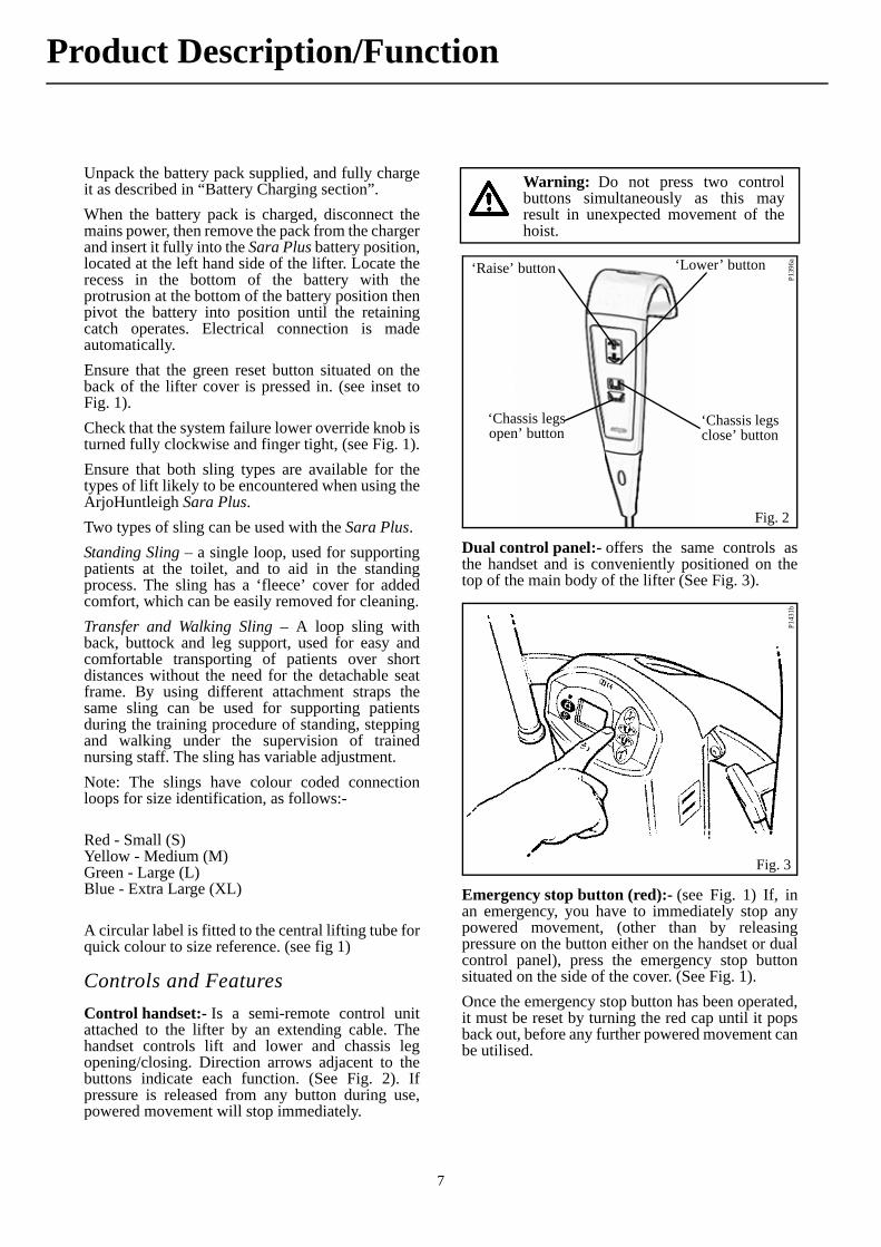
Control handset:- Is a semi-remote control unitattached to the lifter by an extending cable. Thehandset controls lift and lower and chassis legopening/closing. Direction arrows adjacent to thebuttons indicate each function. (See Fig. 2). Ifpressure is released from any button during use,powered movement will stop immediately.
Dual control panel:- offers the same controls asthe handset and is conveniently positioned on thetop of the main body of the lifter (See Fig. 3).
Emergency stop button (red):- (see Fig. 1) If, inan emergency, you have to immediately stop anypowered movement, (other than by releasingpressure on the button either on the handset or dualcontrol panel), press the emergency stop buttonsituated on the side of the cover. (See Fig. 1).
Once the emergency stop button has been operated,it must be reset by turning the red cap until it popsback out, before any further powered movement canbe utilised.
Warning: Do not press two controlbuttons simultaneously as this mayresult in unexpected movement of thehoist.
Fig. 2
P139
6a‘Raise’ button ‘Lower’ button
‘Chassis legs open’ button
‘Chassis legs close’ button
Fig. 3
P143
1b
Product Description/Function

8
Product Description/Function
Power on/Reset button (green):- (see Fig. 1) Onthe rear of the case below the dual control panel.Press this button to turn on power to the lifter. Alsoused to reset if the automatic overload fuse hasoperated (indicated by the button projectingoutwards slightly). If the fuse has operated and oncereset, operates again, withdraw the lifter from useand contact ArjoHuntleigh Service department ortheir appointed distributor.
Power off button (red):- (see Fig. 1) On the rear ofthe case below the dual control panel. Press thisbutton to turn off power to the lifter.
Automatic cut out:- (not an operator control but afunction built into the lifter electronics).
If the lifter is inadvertently overloaded (trying to lifta patient heavier than permitted), an automatic ‘cutout’ operates to prevent the lifter raising a load inexcess of one and a half times the maximum ratedload; this will stop the lift motion automatically.
If this occurs, when pressure is released from the liftbutton on the handset or dual control the electronicswill reset and enable the patient to be lowered only,by pressing either lower button. Remove the patientfrom the lifter.
Automatic stop function:- Great care should betaken not to lower the patient support arms onto thepatient or any other obstruction but if this shouldhappen inadvertently the motor will continue to runbut downward movement will be held by theobstruction. If this occurs release pressure from the‘lower’ button immediately, operate the ‘raise’button until clear, then remove the obstruction.
System failure lower override:- This can be usedin the event of main control failure. In the unlikelyevent that the control handset or dual control panelfails to operate the lifter, with a patient stillsupported by the sling, provision for lowering hasbeen made, using the “lower override knob”,situated on the right hand side of the main cover (seeFig. 4). A label situated above the switch is for quickand easy recognition (see Fig. 1) To operate thelower override, turn the knob anti clockwise half aturn, to cease lowering turn the knob clockwise untilfinger tight only (do not over tighten), only use thisknob in the event of normal control failure do notuse it for normal function lowering.
The lower override will operate whether theemergency stop button has been operated or not.The “automatic stop function” of the jib will stilloperate when using the lower override knob.
When using the Sara Plus normally, always ensurethe system failure lower override knob is alwaysturned fully clockwise and finger tight.
Battery Discharge Indicator:- is a small LEDdisplay which shows the charge condition of thelifter battery. (See Fig. 1 and also ‘Battery ChargingSection’ for complete description).
Hour Meter:- Is a small LCD display (See Fig. 1)which shows the total duration of poweredoperation (in hours). This is primarily intended as anaid to service engineers and to help the attendantcalculate servicing intervals.
Chassis castor Brakes:- The chassis rear castorshave brakes which can be foot operated if required,(see Fig. 5) for example, when leaving the patientunattended, or to keep the Sara Plus in position.
Straight line steering function :- When using theSara Plus for walking practice it may be considereduseful to fix one of the castors to steer in a straightline. This has the effect of allowing the Sara Plus,without assistance to follow the intended straightline walked by the patient. The function is activatedby flipping over the steering guide on the rear castorto hold it in position (see Fig. 5).
Warning: Before operating the loweroverride to lower a patient, always ensurethat a chair or suitable support isunderneath ready to accept the patient.
Fig. 4
P133
2cP
1332
e, f
Fig. 5
Straight line steering guide
9
Arc-Rest (with handgrips):- Integral Part of the Lifting mechanism of the lifter, the intuitive and supportive armrests allow patient participation and comfort during the lifting procedure. (See Fig. 1)
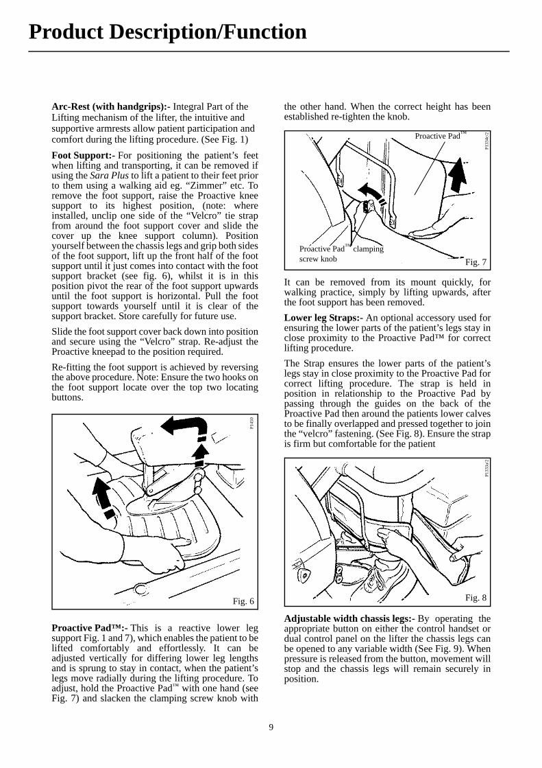
Foot Support:- For positioning the patient’s feetwhen lifting and transporting, it can be removed ifusing the Sara Plus to lift a patient to their feet priorto them using a walking aid eg. “Zimmer” etc. Toremove the foot support, raise the Proactive kneesupport to its highest position, (note: whereinstalled, unclip one side of the “Velcro” tie strapfrom around the foot support cover and slide thecover up the knee support column). Positionyourself between the chassis legs and grip both sidesof the foot support, lift up the front half of the footsupport until it just comes into contact with the footsupport bracket (see fig. 6), whilst it is in thisposition pivot the rear of the foot support upwardsuntil the foot support is horizontal. Pull the footsupport towards yourself until it is clear of thesupport bracket. Store carefully for future use.
Slide the foot support cover back down into positionand secure using the “Velcro” strap. Re-adjust theProactive kneepad to the position required.
Re-fitting the foot support is achieved by reversingthe above procedure. Note: Ensure the two hooks onthe foot support locate over the top two locatingbuttons.
Proactive Pad™:- This is a reactive lower legsupport Fig. 1 and 7), which enables the patient to belifted comfortably and effortlessly. It can beadjusted vertically for differing lower leg lengthsand is sprung to stay in contact, when the patient’slegs move radially during the lifting procedure. Toadjust, hold the Proactive Pad™ with one hand (seeFig. 7) and slacken the clamping screw knob with
the other hand. When the correct height has beenestablished re-tighten the knob.
It can be removed from its mount quickly, forwalking practice, simply by lifting upwards, afterthe foot support has been removed.
Lower leg Straps:- An optional accessory used forensuring the lower parts of the patient’s legs stay inclose proximity to the Proactive Pad™ for correctlifting procedure.
The Strap ensures the lower parts of the patient’slegs stay in close proximity to the Proactive Pad forcorrect lifting procedure. The strap is held inposition in relationship to the Proactive Pad bypassing through the guides on the back of theProactive Pad then around the patients lower calvesto be finally overlapped and pressed together to jointhe “velcro” fastening. (See Fig. 8). Ensure the strapis firm but comfortable for the patient.
Adjustable width chassis legs:- By operating theappropriate button on either the control handset ordual control panel on the lifter the chassis legs canbe opened to any variable width (See Fig. 9). Whenpressure is released from the button, movement willstop and the chassis legs will remain securely inposition.
Fig. 6
P145
0
Fig. 7
P13
34c/
2
Proactive Pad™ clamping screw knob
Proactive Pad™
Fig. 8
P133
3a/2
Product Description/Function

10
Commode Seat (Accessory)
For toileting patients at the chair or bedside or forpatients who cannot be transported with the transfersling, the use of the commode seat and frame is therecommended method of transporting patients overlonger distances. The commode frame is insertedinto the holes in the chassis legs (see Fig. 10), oncethe patient has been lifted to a standing or nearstanding position in the manner previouslydescribed.
Removal of any clothing can be attended to, and thepatient is then lowered down onto the commodeseat. It is recommended that the patient is keptsupported by the sling.
The retractable commode pan, accessible from the
rear of the seat, (see Fig. 11), may be utilised, orremoved to enable the patient to be positioned overa toilet. Apply chassis brakes if leaving the patientunattended.
Transportation should be done with thechassis legs closed, it will be easierthrough doorways etc.
Fig. 9
P133
2d
Warning: At all times the patient and/oroperator should not allow their feet or anyother part of their body to be placed in thearea between the foot support and chassislegs when the chassis legs are closing.
Fig. 10
P133
5d/2
Fig. 11
P133
5e
Product Description/Function
11
Using the Sara Plus for Toiletting and Transporting
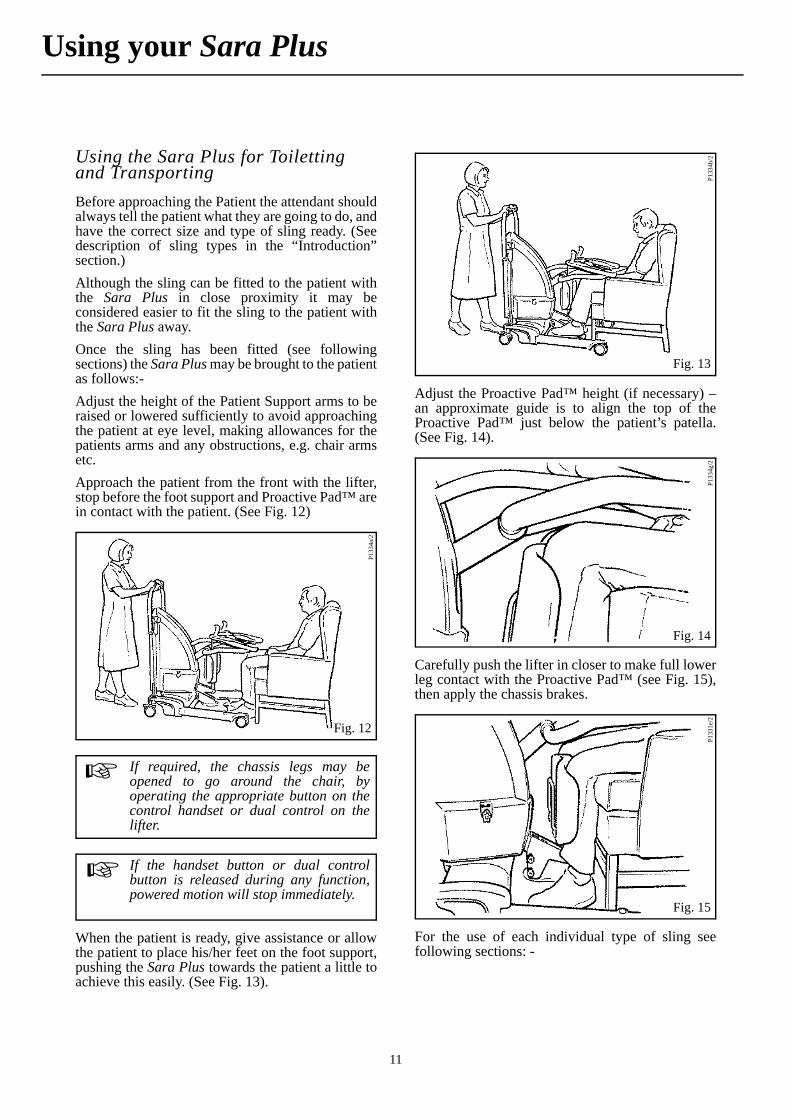
Before approaching the Patient the attendant shouldalways tell the patient what they are going to do, andhave the correct size and type of sling ready. (Seedescription of sling types in the “Introduction”section.)
Although the sling can be fitted to the patient withthe Sara Plus in close proximity it may beconsidered easier to fit the sling to the patient withthe Sara Plus away.
Once the sling has been fitted (see followingsections) the Sara Plus may be brought to the patientas follows:-
Adjust the height of the Patient Support arms to beraised or lowered sufficiently to avoid approachingthe patient at eye level, making allowances for thepatients arms and any obstructions, e.g. chair armsetc.
Approach the patient from the front with the lifter,stop before the foot support and Proactive Pad™ arein contact with the patient. (See Fig. 12)
When the patient is ready, give assistance or allowthe patient to place his/her feet on the foot support,pushing the Sara Plus towards the patient a little toachieve this easily. (See Fig. 13).
Adjust the Proactive Pad™ height (if necessary) –an approximate guide is to align the top of theProactive Pad™ just below the patient’s patella.(See Fig. 14).
Carefully push the lifter in closer to make full lowerleg contact with the Proactive Pad™ (see Fig. 15),then apply the chassis brakes.
For the use of each individual type of sling seefollowing sections: -
Fig. 12
P133
4a/2
If required, the chassis legs may beopened to go around the chair, byoperating the appropriate button on thecontrol handset or dual control on thelifter.
If the handset button or dual controlbutton is released during any function,powered motion will stop immediately.
Fig. 13
P133
4b/2
Fig. 14
P13
34g/
2
Fig. 15
P133
1e/2
Using your Sara Plus

12
Using your Sara Plus
Standing Sling
Allow the patient to hold the handgrips, with theirarms resting on the Arc-Rest. This will not apply iffitting the sling around the patient before the SaraPlus is brought into close proximity.
Encourage the patient to lean slightly forwards toenable the sling to be placed around the lower backof the patient (see Fig. 16). Position the sling aroundthe patient’s back so that the bottom of the sling lieshorizontally approximately two inches above thepatient’s waistline, with the patient’s arms outsidethe sling. Ensure the support strap is separated,brought loosely around the body, and is not twistedor trapped behind the patient’s back.
Fasten the support strap securely by overlappingand pressing the “Velcro” together. The strap shouldbe tight, but comfortable for the patient. (See Fig. 17).
If the Sara Plus is not already in close proximity tothe patient bring it to the patient as describedpreviously.
Take each adjustment cord in turn and attach to thesling. (See Fig. 18).
Warning: Assessment will have to bemade whether the patient requires thelower leg straps, apply if necessary.
Fig. 16
P133
3b
As stated previously, the standing slingmay be applied before the Sara Plus isbrought into position as shown in figure 13.
Warning: The support strap mustalways be applied when using any of theslings.
The support strap will assist insupporting the patient in the sling duringthe lifting procedure. The strap alsoretains the sling in the correct positionaround the patient.
Fig. 17
P13
33c
Fig. 18
P133
3d, e
, fFitting the Loop Lock cord attachment system
Cone
‘Cup’ section
13
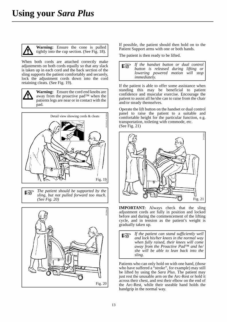
When both cords are attached correctly makeadjustments on both cords equally so that any slackis taken up in each cord and the back section of thesling supports the patient comfortably and securely,lock the adjustment cords down into the cordretaining cleats. (See Fig. 19).
If possible, the patient should then hold on to thePatient Support arms with one or both hands.
The patient is then ready to be lifted.
If the patient is able to offer some assistance whenstanding this may be beneficial to patientconfidence and muscular exercise. Encourage thepatient to assist all he/she can to raise from the chairand/or steady themselves.
Operate the lift button on the handset or dual controlpanel to raise the patient to a suitable andcomfortable height for the particular function, e.g.transportation, toileting with commode, etc. (See Fig. 21)
IMPORTANT: Always check that the slingadjustment cords are fully in position and lockedbefore and during the commencement of the liftingcycle, and in tension as the patient’s weight isgradually taken up.
Patients who can only hold on with one hand, (thosewho have suffered a “stroke”, for example) may stillbe lifted by using the Sara Plus. The patient mayjust rest the unusable arm on the Arc-Rest or hold itacross their chest, and rest their elbow on the end ofthe Arc-Rest, while their useable hand holds thehandgrip in the normal way.
Warning: Ensure the cone is pulledtightly into the cup section. (See Fig. 18).
Warning: Ensure the cord end knobs areaway from the proactive pad™ when thepatients legs are near or in contact with thepad.
Fig. 19
P133
1b/2
, P13
81b
Detail view showing cords & cleats
The patient should be supported by thesling, but not pulled forward too much.(See Fig. 20)
Fig. 20
P133
4e/2
If the handset button or dual controlbutton is released during lifting orlowering powered motion will stopimmediately.
Fig. 21P
1334
f/2
If the patient can stand sufficiently welland lock his/her knees in the normal waywhen fully raised, their knees will comeaway from the Proactive Pad™ and he/she will be able to lean back into thesling.
Using your Sara Plus
14
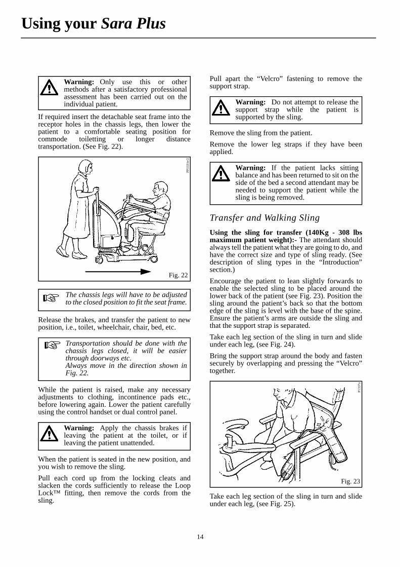
If required insert the detachable seat frame into thereceptor holes in the chassis legs, then lower thepatient to a comfortable seating position forcommode toiletting or longer distancetransportation. (See Fig. 22).
Release the brakes, and transfer the patient to newposition, i.e., toilet, wheelchair, chair, bed, etc.
While the patient is raised, make any necessaryadjustments to clothing, incontinence pads etc.,before lowering again. Lower the patient carefullyusing the control handset or dual control panel.
When the patient is seated in the new position, andyou wish to remove the sling.
Pull each cord up from the locking cleats andslacken the cords sufficiently to release the LoopLock™ fitting, then remove the cords from thesling.
Pull apart the “Velcro” fastening to remove thesupport strap.
Remove the sling from the patient.
Remove the lower leg straps if they have beenapplied.
Transfer and Walking Sling
Using the sling for transfer (140Kg - 308 lbsmaximum patient weight):- The attendant shouldalways tell the patient what they are going to do, andhave the correct size and type of sling ready. (Seedescription of sling types in the “Introduction”section.)
Encourage the patient to lean slightly forwards toenable the selected sling to be placed around thelower back of the patient (see Fig. 23). Position thesling around the patient’s back so that the bottomedge of the sling is level with the base of the spine.Ensure the patient’s arms are outside the sling andthat the support strap is separated.
Take each leg section of the sling in turn and slideunder each leg, (see Fig. 24).
Bring the support strap around the body and fastensecurely by overlapping and pressing the “Velcro”together.
Take each leg section of the sling in turn and slideunder each leg, (see Fig. 25).
Warning: Only use this or othermethods after a satisfactory professionalassessment has been carried out on theindividual patient.
Fig. 22
PP1
331e
/2
The chassis legs will have to be adjustedto the closed position to fit the seat frame.
Transportation should be done with thechassis legs closed, it will be easierthrough doorways etc.Always move in the direction shown inFig. 22.
Warning: Apply the chassis brakes ifleaving the patient at the toilet, or ifleaving the patient unattended.
Warning: Do not attempt to release thesupport strap while the patient issupported by the sling.
Warning: If the patient lacks sittingbalance and has been returned to sit on theside of the bed a second attendant may beneeded to support the patient while thesling is being removed.
Fig. 23
P133
7a
Using your Sara Plus

15
The strap should be tight but comfortable for thepatient. (See Fig. 26).
Give assistance or allow the patient to place his/herfeet on the foot support, pushing the Sara Plustowards the patient a little to achieve this easily.(See Fig. 27).
Adjust the Proactive Pad™ height (if necessary) - toalign the top of the Proactive Pad™ just above thepatients patella, or adjust the pad to its highestposition. (see Fig. 28).
Fig. 24
P133
7b
The support strap will assist insupporting the patient in the sling duringthe lifting procedure.
Fig. 25
P133
7dFig. 26
P133
4a/2
If required, the chassis legs may beopened to go around the chair, byoperating the appropriate button on thecontrol handset or dual control on thelifter.
If the handset button or dual controlbutton is released during any function,powered motion will stop immediately.
Fig. 27
P334
b/2
Using your Sara Plus

16
Identify the attachment loop on each side of thesling and attach the right hand adjustment cord tothe left loop, repeat for the other side (see Fig. 29).See also Fig. 18 for attachment of the cords.
When both cords are attached correctly makeadjustments on both cords equally so that any slackin the cord is taken up.
Identify the support strap on each side of the sling (fitted with a plastic attachment clip), and adjust both straps to their maximum length. Attach each clip to the lug situated on the outer sides of the Arc-Rest (see Fig. 31).
Allow the patient to hold the hand grips with theirarms resting on the Arc-Rest.
Operate the lift button on the handset or dual controlpanel, continue to raise until each support strap is intension and the patient’s back just comes away fromthe chair, then stop the lift. Then adjust both cordsequally to take up any slack, lock both cords into thelocking cleats. (See Fig. 32).
Continue raising until the patient is just clear of theseat.
Fig. 28P1
334d
/2
Fig. 29
P133
7c
Warning: Lock the adjustment cordsdown into the cord retaining cleats (seealso Fig. 30).
Warning: Ensure the cord end knobs areaway from the proactive pad™ when thepatients legs are near or in contact with thepad.
Fig. 30
P133
8a, P
1381
b
Detail view showing cords & cleats
P133
8bFig. 31
Warning: Ensure each clip is attachedcorrectly and secure onto the lug.
Using your Sara Plus

17
If any discomfort is experienced by the patientreturn to the sitting position and re-adjust.
Be careful not to raise the patient too high as thiswill negate the comfort of the transfer sling.
Release the chassis brakes and close the chassislegs, then transport the patient to desiredposition.(See Fig. 33).
Transportation should be done with the chassis legsclosed, it will be easier through doorways etc.
Using the sling for walking practice - (190Kg - 420 lbs maximum patient weight):-
Remove the foot support from the lifter and storecarefully for future use (see “Product Description/Function” section in this manual).
As with all types of lift, before approaching thepatient the attendant should always tell the patientwhat they are going to do, and have the correct sizeand type of sling ready.
Encourage the patient to lean slightly forwards toenable the selected sling to be placed around thelower back of the patient (see Fig. 23). Position thesling around the patient’s back so that the bottomedge of the sling is level with the base of the spine.Ensure the patient’s arms are outside the sling andthat the support strap is separated. Bring the supportstrap around the body and fasten securely byoverlapping and pressing the “Velcro” together. Thestrap should be tight but comfortable for the patient.
Take each leg section of the sling in turn and slideunder each leg (See Fig. 25).
Pull up each leg section strap and connect to eachcorresponding body strap, by connecting bothhalves of the buckles securely (see Fig. 34).
Adjust the straps to be supportive but not restrictive for the patient. (See Fig. 35).
P133
8cFig. 32
Warning: Important: Always checkthat the sling adjustment cords andsupport strap attachment clips are fully inposition and locked before and during thecommencement of the lifting cycle, and intension as the patients weight is graduallytaken up.
Fig. 33
P133
8d
Warning: Apply the chassis brakes ifleaving the patient unattended.
Do not attempt to release the straps orcords while the patient is supported by thesling.
The support strap will assist insupporting the patient in the sling duringthe lifting procedure.
P133
9d
Fig. 34
The leg section strap connection can beperformed after the patient has beenlifted if preferred.
Using your Sara Plus

18
Adjust the height of the Arc-Rest to be as low as possible, making allowances for obstructions, e.g. Chair arms etc.
Approach the patient from the front with the lifter; stop before the Proactive Pad is in contact with the patient. (See Fig. 36).
Adjust the Proactive Pad height (if necessary) - anapproximate guide is to align the top of theProactive Pad just below the patient’s patella. (See Fig. 28).
Carefully push the lifter in closer to make full lowerleg contact with the Proactive Pad, then apply thechassis brakes.
Identify the cord attachment loop on each side of thesling body and attach the cords (Loop Lock methodas previously shown in Fig. 18). When both cordsare attached correctly adjust both cords equally sothat the slack is taken up, but does not pull thepatient forward.
Allow the patient to hold the handgrips with theirarms resting on the Arc-Rest.
Slacken the adjustment on each body support strap(if required), enough to be able to connect theattachment clips to the lugs on the outer sides of theArc-Rest (See Fig. 38).
When the patient is ready, operate the lift button onthe handset or dual control to raise the patient, at thesame time encourage him/her to actively stand (See Fig. 39).
Fig. 35P1
339e
Fig. 36
P133
1d/2
If required, the chassis legs may beopened to go around the chair, byoperating the appropriate button on thecontrol handset or dual control on thelifter.
If the handset button or dual controlbutton is released during any function,powered motion will stop immediately.
Warning: Lock the adjustment cordsdown into the cord retaining cleats. (SeeFig. 37).
Fig. 37
P133
9a, P
1381
bDetail view showing cords & cleats
P133
9c, P
1381
aDetail view of strap attachment
Fig. 38
Using your Sara Plus

19
Continue to raise the Arc-Rest until the patient is ina comfortably supported standing position (seeFig. 40).
If walking practice is to be carried out ensure thepatient is correctly and comfortably supported,adjust the body support straps equally to take up anyslack and be supportive but not too tight and makeadjustment to the Arc-Rest as necessary.
When the patient is standing confidently release thebrakes and pull the lifter slightly away from thepatient until the Proactive Pad is clear of the patientslegs (see Fig. 41).
Re-apply the chassis brakes then carefully removethe Proactive Pad complete with attachment bracketby lifting upwards and store carefully for future use.(See Fig. 42).
With the Pro-Active pad removed and the brakesreleased, the patient will be able to walk at their ownpace, while being supported by the Sara Plus. (See Fig. 43).
P133
9b
Fig. 39P1
339f
Fig. 40
Warning: When the Pro-Active padassembly is removed, ensure that theattachment bracket is also removed beforestarting therapy. Failure to do so could leadto serious injury.
Fig. 41
P134
0aP
1340
b
Fig. 42
The chassis legs may be opened or leftopen to give better clearance for thepatient.
The ‘straight line’ steering lock (if fitted)can be applied over the rear castor as anadditional aid if required.
Using your Sara Plus

20
Using your Sara Plus
Once walking practice has been completed, applythe chassis brakes and replace the Pro-Active pad,return the patient to a chair and when fullysupported, remove the sling by reversing the fittingprocedure.
ArjoHuntleigh Scale (if fitted)
If your Sara Plus has been supplied with the integralScale unit (see Fig. 44), it is possible to weigh apatient during the lifting procedure.
The scale has been designed to weigh hospital orcare facility patients under the supervision oftrained nursing staff. All other uses must beavoided.
Scale Labels
On the labels relating to the Scale you will find thefollowing information:-
Rating and Battery Size Label (attached to the plate behind the lifter battery)
Weight range 1 = 2kg - 120kg (4lbs - 264.6lbs)
d = e 100g (0.2lbs)
Weight range 2 = 4kg - 190kg (10lbs - 419lbs)
d = e 200g (0.5lbs)
d = Actual Scale Division
Serial number label (attached to the plate behind the lifter battery)
Fig. 43
P134
0c
To have better flexion for the leg it may benecessary to slacken the leg strapsslightly, this will allow better legmovement.
Warning: Do not separate the twohalves of the buckles or release theadjustment cords at any stage other thanwhen the patient is seated and fullysupported.
Ensure there are no obstructions in the path before the patient is encouraged to walk.
Warning: When refitting the Pro-Active pad, ensure the pad is reinserted, re-tightened, and covers the support bracket. Failure to do so could lead to serious injury.
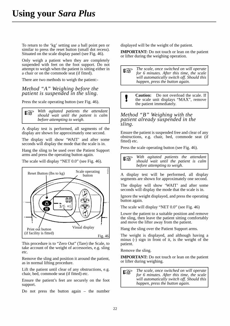
Reset Button (lbs to kg) Scale operating button
Visual displayPrint out button
(if facility is fitted)Fig. 44
mP1
431c

21
Scale Display
The scale has an LCD which displays various numbers and symbols which are explained below (see Fig. 45).
Display symbols /functions
Menu Functions
Shows “Operation” function.
Other functions are only available when calibrating.
Mode Display
B/G – Gross Weight
NET – Net Weight
Battery Symbol
If on – battery power is low.
(Approximately 1 hour of operation left).
All digits flashing – batteries are exhausted.
Lock symbol
Input password. (Only available for special andconfiguration functions. Contact ArjoHuntleighService Department if a password is required).
‘0’ symbol
Displayed when the Scale is in zero range, 25g(0.05lbs).
Dual range symbol
L = Low: 2kg-120kg (4lbs-264.4lbs)
H = High: 4kg-190kg (10lbs-418lbs)
The symbol is displayed for weights over 120kg(264.6lbs).
Min symbol
Displayed when the load is below 2kg (4lbs).
Max symbol
Displayed when the load is above 191.8kg(422.5lbs). If the Scale is overloaded, remove theload immediately. Do no move the Scale/lifter untilthe symbol is switched off.
Trend indicator
Visual weighing range indicator. Blocks aredisplayed which increase from left to right asloading increases.
Unit of measurement
The unit of measurement, in either ‘kg’ or ‘lbs’ willbe preset before delivery. If, for any reason you needto change from ‘kg’ to ‘lbs’, press the operatingbutton for a minimum of 10 seconds.
Upper indicator
Shows weight in kilograms or pounds.
(-) shows, when weight is negative. (See section“Weighing with the Patient already suspended in thesling.”).
Menu function
Mode display
Battery symbol
Upper indicator
Trend indicator
Unit of measurement
(kg or lb)
Maximum symbol
Minimum symbolDual range scale
‘0’ symbolLock symbolFig. 45
P11
22a
Using your Sara Plus
22
Using your Sara Plus
To return to the ‘kg’ setting use a ball point pen orsimilar to press the reset button (small dot recess).Situated on the scale display panel (see Fig. 46).
Only weigh a patient when they are completelysuspended with feet on the foot support. Do notattempt to weigh when the patient is sitting either ina chair or on the commode seat (if fitted).
There are two methods to weigh the patient:-
Method “A” Weighing before the patient is suspended in the sling.
Press the scale operating button (see Fig. 46).
A display test is performed, all segments of thedisplay are shown for approximately one second.
The display will show ‘WAIT’ and after someseconds will display the mode that the scale is in.
Hang the sling to be used over the Patient Supportarms and press the operating button again.
The scale will display “NET 0.0” (see Fig. 46).
This procedure is to “Zero Out” (Tare) the Scale, totake account of the weight of accessories, e.g. slingetc.
Remove the sling and position it around the patient,as in normal lifting procedure.
Lift the patient until clear of any obstructions, e.g.chair, bed, commode seat (if fitted) etc.
Ensure the patient’s feet are securely on the footsupport.
Do not press the button again – the number
displayed will be the weight of the patient.
IMPORTANT: Do not touch or lean on the patientor lifter during the weighing operation.
Method “B” Weighing with the patient already suspended in the sling.
Ensure the patient is suspended free and clear of anyobstructions, e.g. chair, bed, commode seat (iffitted) etc.
Press the scale operating button (see Fig. 46).
A display test will be performed, all displaysegments are shown for approximately one second.
The display will show ‘WAIT’ and after someseconds will display the mode that the scale is in.
Ignore the weight displayed, and press the operatingbutton again.
The scale will display “NET 0.0” (see Fig. 46)
Lower the patient to a suitable position and removethe sling, then leave the patient sitting comfortablyand move the lifter away from the patient.
Hang the sling over the Patient Support arms.
The weight is displayed, and although having aminus (-) sign in front of it, is the weight of thepatient.
Remove the sling.
IMPORTANT: Do not touch or lean on the patientor lifter during weighing.
With agitated patients the attendantshould wait until the patient is calmbefore attempting to weigh.
Reset Button (lbs to kg)
Visual display
Scale operating button
Print out button(if facility is fitted)
Fig. 46
P143
1c
The scale, once switched on will operatefor 6 minutes. After this time, the scalewill automatically switch off. Should thishappen, press the button again.
Caution: Do not overload the scale. Ifthe scale unit displays “MAX”, removethe patient immediately.
With agitated patients the attendantshould wait until the patient is calmbefore attempting to weigh.
The scale, once switched on will operatefor 6 minutes. After this time, the scalewill automatically switch off. Should thishappen, press the button again.
23
With the scale apart from cleaning, no other specialmaintenance should be required.
Calibration
ArjoHuntleigh recommend that your scale ischecked every 12 months for accuracy and thecalibration adjusted if necessary. This must becarried out by an ArjoHuntleigh service engineer.For more information contact your localArjoHuntleigh distributor.
Caution: Do not overload the scale. Ifthe scale unit displays “MAX”, removethe patient immediately.
It is permissible to “Zero Out” (Tare)during operation.
Using your Sara Plus
24
For more details of caring for your lifter batteryrefer to ArjoHuntleigh ‘Battery Care’ literature, PartNo. KDX01660.GB.
The Sara Plus incorporates a battery dischargeindicator, situated on the right hand side of the cover(see Fig. 1). The display shows ten levels of batterystate ranging from fully charged on the right to verylow on the left (green, through yellow to red).
It is recommended that the battery is removed fromthe lifter and recharged when the display reaches theyellow range, but lifting is possible until the displayshows the red flashing light, at this point, the batterymust be recharged as soon as possible.
Recharging the battery pack before it reaches a lowstate of battery charge or certainly totally dischargedwill prolong its life.
Warning: The charging of the batterymust only be performed away from thepatient environment.
The charger is for indoor use only.
Only use the charger unit in a dryenvironment, do not use it in the bathroom.
Do not expose the charger unit or batterypack to rain or spray and do not immerse inwater.
Do not expose the charger unit to dust.
To avoid overheating, the charger must notbe covered whilst in use.
No smoking or naked flames in batteryvicinity.
The battery charger is for use only withArjoHuntleigh supplied batteries that areto be used with the Sara Plus.
The battery charger is for use with sealedlead acid batteries only.
Under no circumstances should thecharger be used to attempt to recharge non-rechargeable batteries.
Do not attempt to open or tamper with thecharger unit in any way, for any repair thecharger must be sent to the manufacturer.
The mains electricity socket must be easilyaccessible. Should a faulty condition occurswitch off and remove the connection plugfrom the socket.
Only use ArjoHuntleigh components thathave been specifically designed for thepurpose when charging batteries
Only use the ArjoHuntleigh battery that issupplied to be used with the Sara Plus.
Only use the ArjoHuntleigh charger unitsupplied with the Sara Plus.
Do NOT charge batteries in a sealedcontainer.
Do NOT place batteries near, or disposeof, in a fire.
Do NOT short circuit a battery.
Do NOT store batteries at temperatures inexcess of 60°C (140°F).
Warning: Do NOT crush, puncture,open, dismantle or otherwisemechanically interfere with batteries.
Should the battery casing become cracked,and electrolyte come into contact with skinor clothing, wash immediately with water.
Should the battery casing become cracked,and electrolyte come into contact with skinor clothing, wash immediately with water.
If the electrolyte contacts the eyes, washimmediately with copious amounts ofwater, and seek medical attention.
When disposing of batteries, contact theappropriate local authority for advice.
The abbreviation “Pb” shown adjacent tothe recycling and trash bin symbols on thebattery back label is the element symbolfor lead, and indicates that the batterycontains lead and therefore should not bedisposed of in the normal manner but mustbe recycled.
Ensure the battery is removed from thelifter if it is anticipated it will not be usedfor a prolonged period of time.
The battery discharge indicator has anenergy saving function, automaticallyswitching off the display if a functionbutton has not been operated for at least30 seconds. The moment a button ispressed to operate any function, thedisplay will re-start.
Battery Charging
25
Battery Charging
Your lifter is fitted with an audible warning devicethis will sound when the battery discharge indicatorreaches the red light range.
To ensure the Sara Plus is always ready for use, it isrecommended that a freshly charged battery pack isalways available. This is achieved by havingadditional battery packs available and keeping oneon charge while the other is in use.
It may be considered good protocol to have a freshlycharged battery ready for the start of every workshift.
Place the battery pack on charge as follows:
When the LEDs on the battery discharge indicatordisplay amber, complete your lift cycle then take thelifter to a convenient situation and remove thebattery pack by holding the grip position of thebattery and pressing the release catch situatedabove, pivot the battery away and lift clear. Take thebattery to the battery charger unit and ensure thebattery is positioned securely then insert the batteryconnector from the charger into the correspondingconnector in the back of the battery, switch on mains
power. An orange light will be displayed on thecharger unit when the battery is totally discharged.This will change to a yellow light as the batteryapproaches full charge capacity, finally changing toa green light when the battery is fully charged.
A discharged battery should be left approximately 8hours to totally recharge (See also ArjoHuntleighBattery Care document).
When the battery pack is fully charged, disconnectthe mains power, remove the battery pack from thecharger, and insert it back into the Sara Plus batteryposition.
Ensure the green reset button (situated on the rear ofthe mast) is pressed in (see Fig. 1).
The Sara Plus is now ready for use.
Whichever level the indicator hasreached, once a fully charged battery isre-inserted into the lifter, the display willreturn to the green fully charged position,but if a partially charged battery is re-inserted, the level at which the indicatorhad reached will remain, even though therecently inserted battery may be in abetter state of charge than indicated. Toachieve a true indication of battery statea fully charged battery must be insertedinto the lifter to reset the indicator.
Caution: Ensure the mains power tothe charger unit is switched off beforeconnecting the battery.
The cable that connects the mainelectricity supply to the charger issupplied as a detachable item. If usingthe battery charger for the first time or ifthe cable has been unplugged from thecharger, connect the cable fully into thecharger before connecting to the mainselectrical socket.
Warning: Always ensure the cableconnection plugs that fit into the chargerand into the battery are fully insertedbefore switching on mains electricity.
Warning: Hold the pack firmly toensure it does not drop and becomedamaged, or cause personal injury.
The battery pack may be left connected tothe charger unit when it is fully chargedwithout being damaged by overcharging,this will also ensure the battery is keptfully charged.
Caution: Always disconnect the mainssupply before disconnecting the batteryfrom the charger unit.
Caution: Turn off the hoist after use bypressing the red Power off button (see Fig.1). This will reduce power consumption.
26
Care of your Sara Plus
General Lifter Care
How often the following actions are taken dependson how often the equipment is used.
Unless otherwise stated, it is a good idea to beginonce a week and then rely on experience to decidehow often it is necessary in the future.
The Polyester fleece sling cover may be removedfrom the sling cushion assembly for laundering. Toremove the cover, undo the tie cords at each end ofthe sling, open up the ‘Velcro’ seam and remove.Secure the tie cords with a knot before laundering.
For cleaning your lifter, equipment and accessorieswipe down with a damp cloth using warm water towhich a disinfectant/cleaner has been added e.g.
“ARJO CLEAN” - disinfectant/cleaner orequivalent.
Ensure that the battery pack is always in a good stateof charge.
Check that the lifter can be propelled in a normalmanner, making sure that the castors are quite freein their movement, as clogging by hair and fluff canoccur, also check that the tread of the castor is notdamaged.
Warning: The slings should be checked,and if necessary washed according toinstructions on the sling, also refer to slinginstruction sheet MAX.01520.INT.
Warning: With regard to laundering,slings should not be classified as linen,but as an accessory to a patient transferlifter and therefore classified as a medicaldevice. Slings should be cleaned anddisinfected only in strict accordance withthe manufacturers instructions.
ArjoHuntleigh strongly recommends thatthe support strap is removed from the slingprior to washing, this is to prevent ‘velcro’hook damage to the fabric of the sling. Thesupport strap should be washed separatelywith the ‘velcro’ patches in the ‘closed’position i.e.: fold the strap, over on itselfand press ‘velcro’ mating halves together.Always ensure the support strap isreconnected to the sling before use.
Mechanical pressure should be avoidedduring the washing and drying proceduree.g. rolling or pressing, as these candamage parts vital to the safe andcomfortable operation of the sling.
It is recommended that ArjoHuntleighPatient lifters, equipment, accessories andslings are regularly cleaned. If the slings,lifters and equipment needs cleaning, orare suspected of being contaminated,follow the cleaning and/or disinfectionprocedures recommended below, beforere-using the equipment. This is especiallyimportant when using the same equipmentfor another patient, to minimise the risk ofcross infection.
Warning: The lifter should be cleanedbefore it is used by another patient.
ARJO CLEAN - disinfectant cleaner isavailable from ArjoHuntleigh or theirapproved distributors.
Caution: Do not over wet areas of theproduct which could cause problems withelectrical components or internalcorrosion.
If a hot air dryer is used to dry the lifter, thetemperature must not exceed 80°C(176°F).
Do not use petroleum based solvents orsimilar, since this may damage plasticparts.
Warning: For disinfection ofcontaminated lifters, equipment andaccessories, use the preferred method ofwiping the product completely with “hardsurface disinfectant wipes” that aresupplied impregnated with a 70% v/vsolution of Isopropyl Alcohol.
A rubbing action will be necessary whenusing the wipes to promote effectivedisinfection of the surfaces.
Warning: IMPORTANT: Cleaningand disinfection products must be used inaccordance with the manufacturersinstructions and suitable eye, hand andclothing protection must be worn at alltimes when handling disinfectants.
70% v/v Isopropyl Alcohol wipes havebeen proved to be effective against MRSAand several other micro-organisms underlight soiling conditions.
27
Care of your Sara Plus
Environmental Advice
This device is marked with the WEEEsymbol (crossed-out wheeled bin) toindicate that it is electronic equipmentcovered by the Directive 2002/96/EC on
waste electrical and electronic equipment. This is aEuropean directive but applies worldwide. InEuropean countries the WEEE symbol reminds youthat all electrical and electronic products must betaken to a separate collection at the end of theirworking life. Do not dispose of this product innormal domestic or commercial waste - contactyour local authority for advice on disposal
Periodic Testing
For normal operation - raise and lower the PatientSupport arms using the control handset and dualcontrol panel, this is to test for full and efficientmovement.
Automatic Stop Function:- With the PatientSupport arms raised well above its lowest position,using the control handset lower it, and at the sametime with your other hand hold the Patient Supportarms up briefly. The motor will continue to runwhile the Patient Support arms weight is held, this isquite normal, release the button, then lower thePatient Support arms carefully. Repeat this checkusing the dual control lower button on the lifter. Thischeck is for the correct function of the automaticstop.
Emergency Stop:- Test the emergency stop facilityby operating the control handset to lift or lower thepatient support arms, and whilst operating, press inthe emergency stop button. (See Fig. 1). Poweredmovement should stop immediately.
Reset to normal function by pressing the green resetbutton. (See Fig. 1). Repeat for chassis legsopening / closing function, and reset the button.
Adjustable Width Chassis Function:- Open andclose the chassis legs using the control handset tocheck for full and efficient movement.
General Lifter Condition:- A general visualinspection of all external parts should be carried out,and all functions should be tested for correctoperation, to ensure that no adverse damage hasoccurred during use.
Cleaning and Disinfecting the Toilet Commode Chair and Frame (if fitted)
For exterior areas of the seat and frame the “hardsurface disinfectant wipes” mentioned above will bevery effective, but for internal and crevice areas ofthe equipment ArjoHuntleigh recommend that theseat and frame is cleaned in accordance with yournormal cleaning and disinfecting protocol.
Disassembly of the Commode Seat
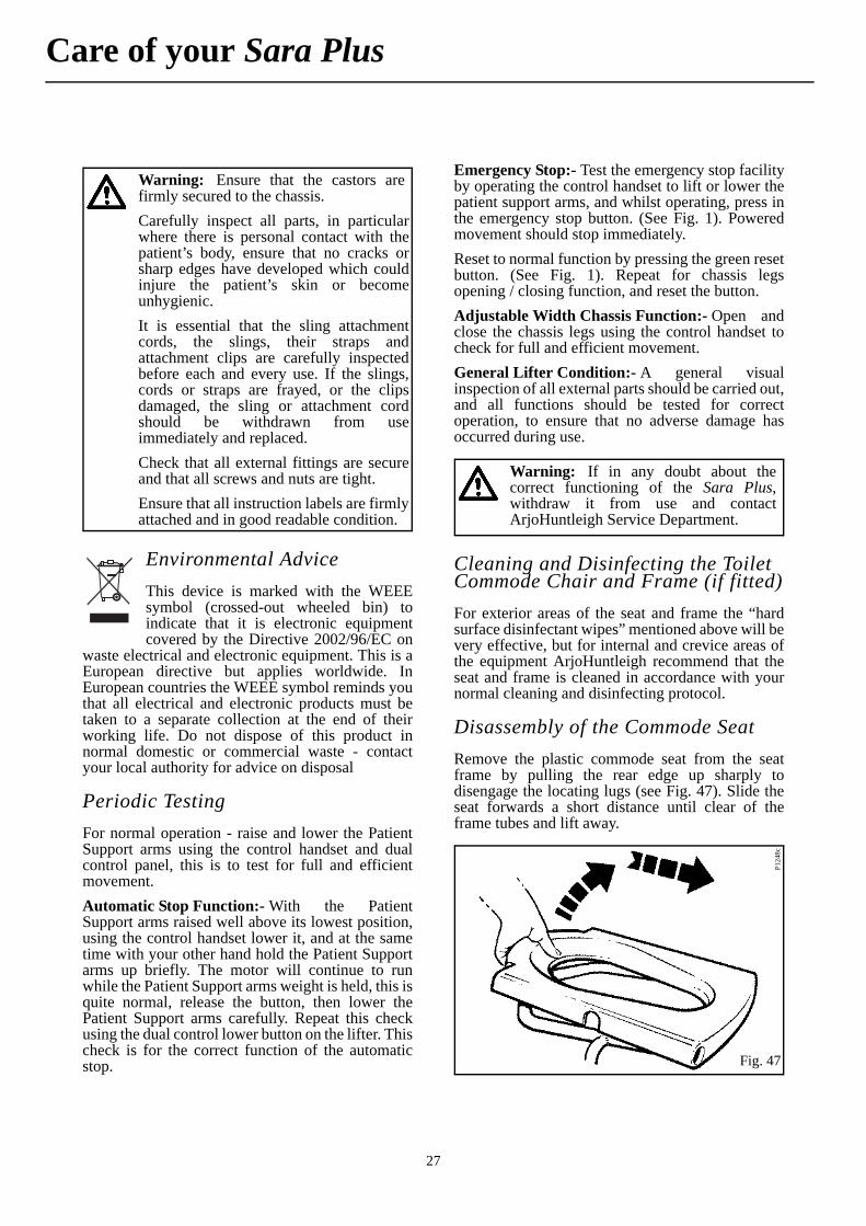
Remove the plastic commode seat from the seatframe by pulling the rear edge up sharply todisengage the locating lugs (see Fig. 47). Slide theseat forwards a short distance until clear of theframe tubes and lift away.
Warning: Ensure that the castors arefirmly secured to the chassis.
Carefully inspect all parts, in particularwhere there is personal contact with thepatient’s body, ensure that no cracks orsharp edges have developed which couldinjure the patient’s skin or becomeunhygienic.
It is essential that the sling attachmentcords, the slings, their straps andattachment clips are carefully inspectedbefore each and every use. If the slings,cords or straps are frayed, or the clipsdamaged, the sling or attachment cordshould be withdrawn from useimmediately and replaced.
Check that all external fittings are secureand that all screws and nuts are tight.
Ensure that all instruction labels are firmlyattached and in good readable condition.
Warning: If in any doubt about thecorrect functioning of the Sara Plus,withdraw it from use and contactArjoHuntleigh Service Department.
Fig. 47
P124
8c
28
Care of your Sara Plus
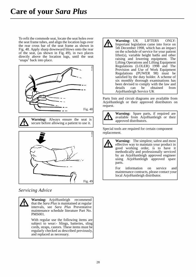
To refit the commode seat, locate the seat holes overthe seat frame tubes, and align the location lugs overthe rear cross bar of the seat frame as shown inFig. 48. Apply sharp downward blows onto the rearof the seat, (as shown in Fig. 49), in two placesdirectly above the location lugs, until the seat‘snaps’ back into place.
Servicing Advice
Parts lists and circuit diagrams are available fromArjoHuntleigh or their approved distributors onrequest.
Special tools are required for certain component replacement.
Fig. 48
P12
48a
Warning: Always ensure the seat issecure before allowing a patient to use it.
Fig. 49
P12
48b
Warning: ArjoHuntleigh recommendthat the Sara Plus is maintained at regularintervals, see Sara Plus Preventativemaintenance schedule literature Part No.PMS001.
With regular use the following items aresubject to wear:- Slings, batteries, slingcords, straps, castors. These items must beregularly checked as described previously,and replaced as necessary.
Warning: UK LIFTERS ONLY:Important legislation came into force on5th December 1998, which has an impacton the schedule of service for your patientlifter(s), variable height baths and otherraising and lowering equipment. TheLifting Operations and Lifting EquipmentRegulations (LOLER) 1998 and TheProvision and Use of Work EquipmentRegulations (PUWER 98) must besatisfied by the duty holder. A scheme ofsix monthly thorough examinations hasbeen devised to comply with the law anddetails can be obtained fromArjoHuntleigh Service UK
Warning: Spare parts, if required areavailable from ArjoHuntleigh or theirapproved distributors.
Warning: The simplest; safest and mosteffective way to maintain your product ingood working order, is to have itmethodically and professionally servicedby an ArjoHuntleigh approved engineerusing ArjoHuntleigh approved spareparts.
For information on service andmaintenance contracts, please contact yourlocal ArjoHuntleigh distributor.
29
Labels
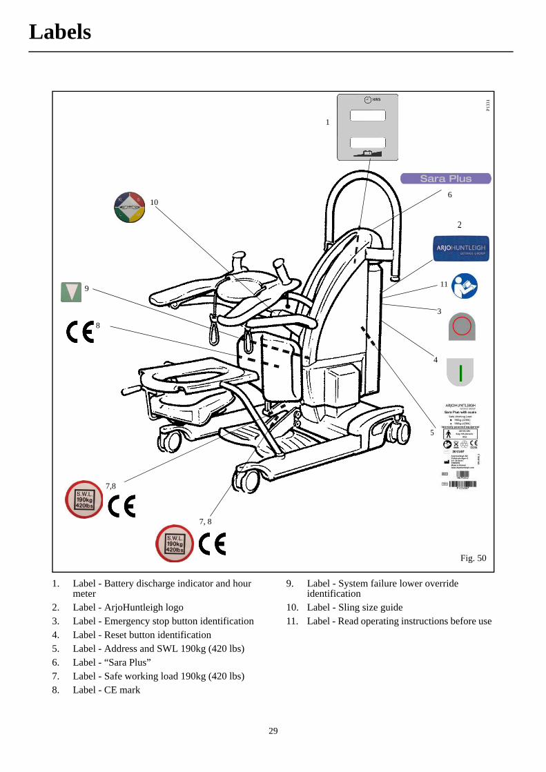
1. Label - Battery discharge indicator and hour meter
2. Label - ArjoHuntleigh logo3. Label - Emergency stop button identification4. Label - Reset button identification5. Label - Address and SWL 190kg (420 lbs)6. Label - “Sara Plus”7. Label - Safe working load 190kg (420 lbs)8. Label - CE mark
9. Label - System failure lower override identification
10. Label - Sling size guide11. Label - Read operating instructions before use
Fig. 50
P133
1
1
2
3
4
5
6
7, 8
7,8
8
9
10
11
30
Technical Specification
Component Weights
kg (lbs)
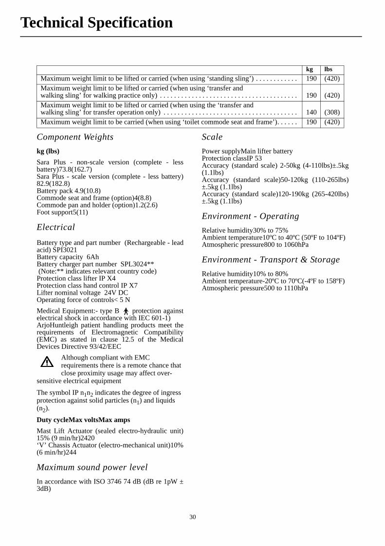
Sara Plus - non-scale version (complete - lessbattery)73.8(162.7)Sara Plus - scale version (complete - less battery)82.9(182.8)Battery pack 4.9(10.8)Commode seat and frame (option)4(8.8)Commode pan and holder (option)1.2(2.6)Foot support5(11)
Electrical
Battery type and part number (Rechargeable - leadacid) SPI3021Battery capacity 6AhBattery charger part number SPL3024** (Note:** indicates relevant country code)Protection class lifter IP X4Protection class hand control IP X7Lifter nominal voltage 24V DCOperating force of controls< 5 N
Medical Equipment:- type B protection againstelectrical shock in accordance with IEC 601-1)ArjoHuntleigh patient handling products meet therequirements of Electromagnetic Compatibility(EMC) as stated in clause 12.5 of the MedicalDevices Directive 93/42/EEC
Although compliant with EMC requirements there is a remote chance that close proximity usage may affect over-
sensitive electrical equipment
The symbol IP n1n2 indicates the degree of ingress protection against solid particles (n1) and liquids (n2).
Duty cycleMax voltsMax amps
Mast Lift Actuator (sealed electro-hydraulic unit)15% (9 min/hr)2420‘V’ Chassis Actuator (electro-mechanical unit)10%(6 min/hr)244
Maximum sound power level
In accordance with ISO 3746 74 dB (dB re 1pW ±3dB)
Scale
Power supplyMain lifter batteryProtection classIP 53Accuracy (standard scale) 2-50kg (4-110lbs)±.5kg(1.1lbs)Accuracy (standard scale)50-120kg (110-265lbs)±.5kg (1.1lbs)Accuracy (standard scale)120-190kg (265-420lbs)±.5kg (1.1lbs)
Environment - Operating
Relative humidity30% to 75%Ambient temperature10ºC to 40ºC (50ºF to 104ºF)Atmospheric pressure800 to 1060hPa
Environment - Transport & Storage
Relative humidity10% to 80%Ambient temperature-20ºC to 70ºC(-4ºF to 158ºF)Atmospheric pressure500 to 1110hPa
kg lbs
Maximum weight limit to be lifted or carried (when using ‘standing sling’) . . . . . . . . . . . . 190 (420)Maximum weight limit to be lifted or carried (when using ‘transfer andwalking sling’ for walking practice only) . . . . . . . . . . . . . . . . . . . . . . . . . . . . . . . . . . . . . . . 190 (420)Maximum weight limit to be lifted or carried (when using the ‘transfer andwalking sling’ for transfer operation only) . . . . . . . . . . . . . . . . . . . . . . . . . . . . . . . . . . . . . . 140 (308)Maximum weight limit to be carried (when using ‘toilet commode seat and frame’). . . . . . 190 (420)
31
Technical Specification
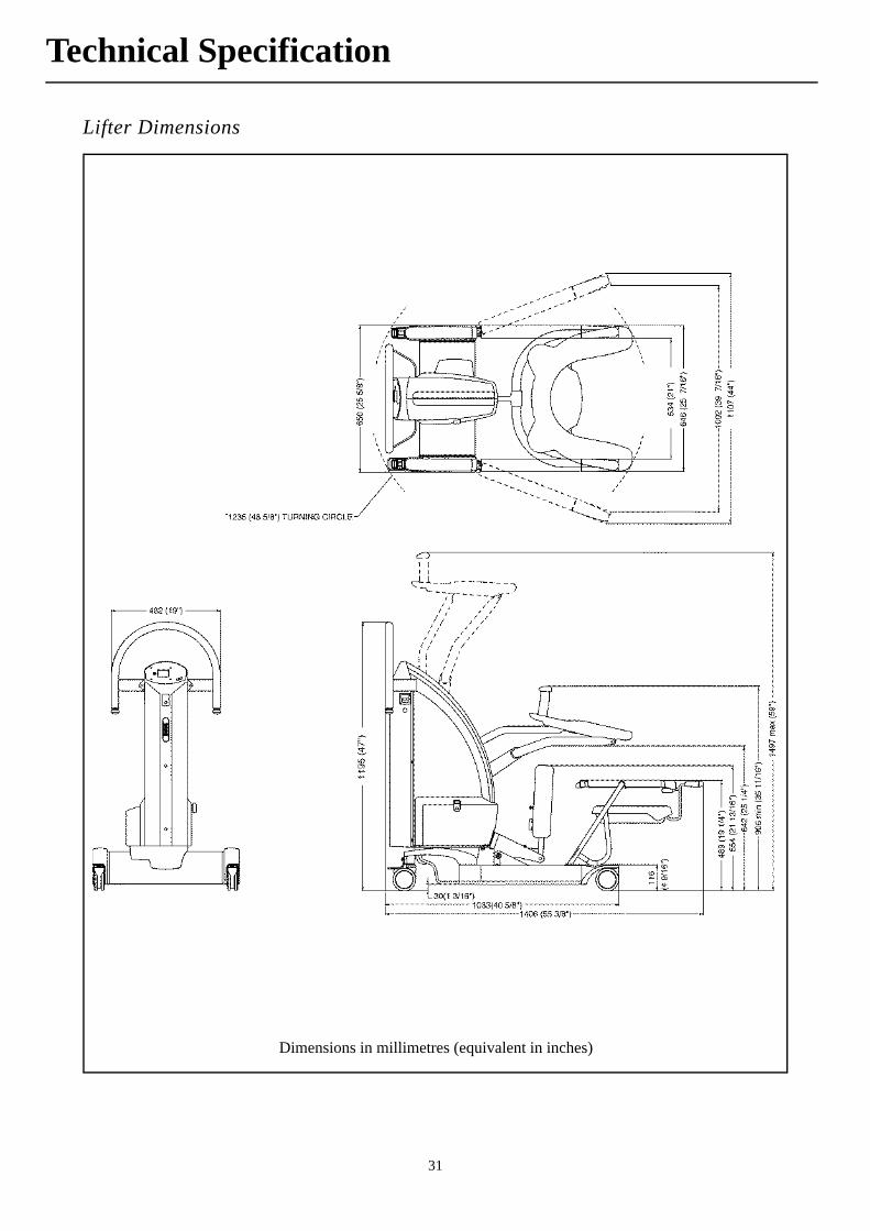
Lifter Dimensions
Dimensions in millimetres (equivalent in inches)
32
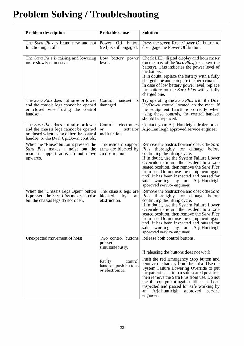
Problem description Probable cause Solution
The Sara Plus is brand new and notfunctioning at all.
Power Off button(red) is still engaged.
Press the green Reset/Power On button todisengage the Power Off button.
The Sara Plus is raising and loweringmore slowly than usual.
Low battery powerlevel.
Check LED, digital display and hour meter(on the mast of the Sara Plus, just above thebattery). This indicates the power level ofthe battery.If in doubt, replace the battery with a fullycharged one and compare the performance.In case of low battery power level, replacethe battery on the Sara Plus with a fullycharged one.
The Sara Plus does not raise or lowerand the chassis legs cannot be openedor closed when using the controlhandset.
Control handset isdamaged
Try operating the Sara Plus with the DualUp/Down control located on the mast. Ifthe equipment functions correctly whenusing these controls, the control handsetshould be replaced.
The Sara Plus does not raise or lowerand the chassis legs cannot be openedor closed when using either the controlhandset or the Dual Up/Down controls.
Control electronicsor actuatormalfunction
Contact your ArjoHuntleigh dealer or anArjoHuntleigh approved service engineer.
When the “Raise” button is pressed, theSara Plus makes a noise but theresident support arms do not moveupwards.
The resident supportarms are blocked byan obstruction
Remove the obstruction and check the SaraPlus thoroughly for damage beforecontinuing the lifting cycle.If in doubt, use the System Failure LowerOverride to return the resident to a safeseated position, then remove the Sara Plusfrom use. Do not use the equipment againuntil it has been inspected and passed forsafe working by an ArjoHuntleighapproved service engineer.
When the “Chassis Legs Open” buttonis pressed, the Sara Plus makes a noisebut the chassis legs do not open.
The chassis legs areblocked by anobstruction.
Remove the obstruction and check the SaraPlus thoroughly for damage beforecontinuing the lifting cycle.If in doubt, use the System Failure LowerOverride to return the resident to a safeseated position, then remove the Sara Plusfrom use. Do not use the equipment againuntil it has been inspected and passed forsafe working by an ArjoHuntleighapproved service engineer.
Unexpected movement of hoist Two control buttonspressedsimultaneously.
Faulty controlhandset, push buttonsor electronics.
Release both control buttons.
If releasing the buttons does not work:
Push the red Emergency Stop button andremove the battery from the hoist. Use theSystem Failure Lowering Override to putthe patient back into a safe seated position,then remove the Sara Plus from use. Do notuse the equipment again until it has beeninspected and passed for safe working byan ArjoHuntleigh approved serviceengineer.
Problem Solving / Troubleshooting

33
This product complies with the requirements ofapplicable standards for electromagneticcompatibility (EMC). However, medical electricalequipment such as the Sara Plus requires specialprecautions regarding EMC and should be installedand used in accordance with the information below.
Warning: Wireless communicationsequipment such as wireless computernetwork devices, mobile phones, cordlesstelephones and their base stations, walkie-talkies, etc. can affect this equipment andshould be kept at least 1.5m away fromthe equipment.
Guidance and manufacturer’s declaration: electromagnetic emissions (EMI)Emissions test Compliance Electromagnetic environment - guidance
RF emissionsCISPR11
Group 1 This equipment uses RF energy only for its internal functions.Therefore its RF emissions are very low and are not likely tocause any interference in nearby electronic equipment.
RF emissionsCISPR 11
Class B This equipment is suitable for use in all establishments, in-cluding domestic establishments and those directly connectedto the public low voltage power supply network that suppliesbuildings used for domestic purposes.
Guidance and manufacturer’s declaration: electromagnetic immunityImmunity test IEC60601 test level Compliance level Electromagnetic environment - guid-
ance
Electrostatic discharge(ESD)IEC61000-4-2
±6kV contact±8kV air
±6kV contact±8kV air
Floors should be wood, concrete orceramic tile. If floors are covered withsynthetic material the relative humid-ity level should be at least 30%
Radiated RFIEC 61000-4-6
3V rms80MHz to 2.5GHz
3V rms80MHz to 2.5GHz
Portable and mobile RF communica-tions equipment should be used nocloser to any part of the Sara Plus, in-cluding cables, than 1.0m, if the trans-mitter’s output power rating exceeds1W (a)
Field strengths from fixed RF trans-mitters, as determined by an electro-magnetic site survey, should be lessthan the compliance level in each fre-quency range (b)
Interference may occur in the vicinityof equipment marked with this sym-bol:
a) Field strengths from fixed transmitters, such as base stations for cellular/cordless telephones and land mobile radios,amateur radio, AM and FM radio broadcast and TV broadcast cannot be accurately predicted theoretically. To assess theelectromagnetic environment due to fixed RF transmitters, an electromagnetic site survey should be considered. If themeasured field strength in the location in which the Sara Plus is used exceeds the applicable RF compliance level above,the Sara Plus should be observed to verify normal operation. If abnormal performance is observed. additional measuresmay be necessary.b) Over the frequency range 150kHz to 80MHz, field strength should be less than 1V/m.
Recommended separation distances between portable and mobile RF communications equipment and the Sara PlusThe Sara Plus is intended for use in an electromagnetic environment in which radiated RF disturbances are controlled.The customer and user of the Sara Plus can help prevent electromagnetic interference by maintaining a minimum dis-tance between portable and mobile RF communications equipment (transmitters) and the Sara Plus by maintaining adistance of not less than 1 metre to any part of the Sara Plus, including cables, if the transmitter’s output power ratingexceeds 1W.
Electromagnetic Compatibility