sap-1 locating of normal transitions in a high temperature
TRANSCRIPT

Locating of Normal Transitions in a High Temperature Superconducting Coil by Non-Destructive Voltage Detection
Method
N.Nanato, K.Nishiyama*, S.Hesaka, K.Okura
(Department of Electrical and Electronic Engineering, Division of Industrial Innovation
Sciences, Graduate School of Natural Science and Technology, Okayama University
3-1-1 Tsushima Naka, Kita-ku, Okayama, 700-8530, Japan)
Locating of normal transitions in high temperature superconducting (HTS) coils is important for protection and
safety design of HTS equipment. Generally, a method to locate the normal transitions is to solder directly many
voltage taps on the HTS coils. However because it is necessary to remove electrical insulations on HTS wires for
the soldering, insulation characteristics of the HTS coils are deteriorated. The presenters have presented a
non-destructive voltage measurement method [1] that can detect the normal transitions without removing the
insulations. In this method, two electro-conductive sheets are attached on a surface of an HTS coil and are
connected with an outside capacitor, and then the normal transitions can be detected as a voltage of the outside
capacitor by voltage dividing with the three capacitors. In this presentation, precise locating of the normal
transitions in a HTS coil by the capacitor taps is presented.
[1] N.Nanato, K.Nishiyama : Non-destructive detection of normal transitions in high temperature
superconducting coil, Physics Procedia, printed.
Figure 1. Outline of the non-destructive voltage measurement method
SAP-1

Development of the current bypassing methods into the transverse
direction on non-insulation HTS coils
K. Tanaka*, S.B.Kim, H. Ikoma, D. Kanemoto
(Graduate School of Natural Science and Technology, Okayama University, 3-1-1,
Tsushima Naka, Kita-ku, Okayama 700-8530, Japan)
In the case of motors and generators, the benefits of using high temperature superconducting (HTS) coils can be
represented by the reduction of 50% in both losses and sizes compared to conventional machines. However, it is
hard to establish quench detection and protection devices for the HTS coils applied to the rotors of motors and
generators. So, the stability of the coils is lower than for the quiescent coils applied to NMR, MRI and so on.
Therefore, it is important to improve the self-protection ability of HTS coils. We have studied the methods to
improve the self-protection ability of HTS coils by removing the turn-to-turn insulation and inserting metal tape
instead of the electrical insulation. The operating current in the non-insulated HTS coil was bypassed into the
transverse direction by the generated normal region because of their electrical contact among the winding. In this
study, we examined the method to control the current bypassing on layer-to-layer for controlling the inductance of
the non-insulated HTS coil. It is necessary to create a normal region in the HTS coil in order to bypass the current
into the transverse direction, so the design issues about the shape of heaters to make a normal zone and its location
are very important. The optimized positions of heater and current bypassing properties on non-insulated HTS coil
wound with 2G wires with / without stabilizer will be discussed.
SAP-2
Critical Current Estimation of 2G HTS Coils considering Magnetic Field Angular Dependency
S. Baik*,1
, M. Sohn1, K. Shim
1
(1Korea Electrotechnology Research Institute)
In the heavy ion accelerator there are lots of superconducting magnets that are used for controlling rare isotope
beams. Among those magnets some are located near highly radiation area such as near to beam target, where
superconducting magnet should have high stability against temperature rise due to the radiation. For this area
High-Temperature Superconducting (HTS) magnet system has been issued for an alternative because it has higher
operating temperature than Low-Temperature Superconducting magnet operating in liquid helium.
In this paper we consider HTS coils wound with the 2nd Generation (2G) HTS conductor that has higher
critical current than the 1st Generation (1G) HTS coil in magnetic field. Different from 1G HTS conductor 2G HTS
conductor shows special variation pattern of the critical current according to the magnetic field angular direction to
the surface of conductor. So we will estimate the critical current of 2G HTS model coils in consideration of the
angular dependency.
SAP-3

Investigation of the Electromagnetic Behaviors of HTS Coils in a Time-Varying Magnetic Field
Y. H. Choi*, H. J. Shin, D. H. Kang, S. G. Kim, and H. G. Lee
Department of Materials Science and Engineering, Korea University, Korea
The electromagnetic behaviors of two GdBCO racetrack coils, one wound without turn-to-turn insulation (NI) and
the other wound with Kapton tape (INS), were examined in a time-varying magnetic field. The currents induced by
the electro motive forces (EMFs) in the coils were measured with respect to the rotating speed, number of turns, and
the distance (d) between the permanent magnet and coil. During tests in rotating fields (5 rpm and d = 10 mm),
induced current delay was observed in the NI coil due to the anisotropy of the current path through the turn-to-turn
contacts in the radial direction, as well as its original spiral path in the winding direction. Consequently, the maximum
induced current of the NI coil was measured to be much lower than that of the INS coil. Moreover, the induced
currents in the INS coil increased with increasing rotating speed and number of turns, as well as with decreasing d,
while those of the NI coil were barely affected due to the anisotropic current path. The experimental results were
compared with the analytical results calculated using an equivalent circuit model. The simulated results showed good
agreement with the experimental results, supporting the validity of the theoretical analysis based on the equivalent
circuit model.
< Acknowledgment>
This work was supported by the International Collaborative R&D Program of the KETEP grant funded
by the Korean government MKE (20118520020020). This work was also supported by the Mid-Career
Researcher Program through an NRF grant funded by the MEST (2012-046999).
SAP-4

Influence of the Lorentz Force on the Characteristic Resistance of a No-Insulation Racetrack Pancake Coil
K. L. Kim*, Y. H. Choi, D. G. Yang, D. H. Kang, and H. G. Lee
Department of Materials Science and Engineering, Korea University, Korea
Conventional methods for joining second-generation (2G) high-temperature superconducting (HTS) tapes employ
soldering techniques that yield high joint resistance. While there is ongoing research to reduce joint resistance, Joule
heating in the joining region is still inevitable in non-superconducting joints. Recently, we reported the world’s first
superconducting joint for GdBa2Cu3O7-δ (GdBCO) tapes, in which a direct connection between two superconducting
layers was formed without soldering. The production of this superconducting joint requires a series of processes
including the fabrication of microholes by lasers, peeling off of the stabilizers, heat treatment for joining in a vacuum,
and oxygenation annealing under high pressured oxygen. Unlike conventional resistive splices, there is essentially
no resistance in the superconducting joint to the flow of electricity between the tapes. The resulting joint exhibits the
same electrical characteristics observed in the parent tape, which represents a breakthrough for applications that
would otherwise be impossible using conventional 2G HTS splicing methods. This unique joining technique will
provide unprecedented freedom to research scientists and development engineers for the design and manufacture of
novel 2G HTS systems.
< Acknowledgment>
This work was supported by the International Collaborative R&D Program of the KETEP grant funded
by the Korean government MKE (20118520020020). This work was also supported by the Mid-Career
Researcher Program through an NRF grant funded by the MEST (2012 -046999).
SAP-5
Study on the Discharge Characteristics of Partially-Insulated (PI) GdBCO Coils with Respect to Winding Scheme
D. G. Yang*, Y. H. Choi, D. H. Kang, S. G. Kim, and H. G. Lee
Department of Materials Science and Engineering, Korea University, Korea
Recently, we suggested the use of partial insulation (PI) coils as a potential solution for the problem of slow
charge/discharge rates experienced by no insulation (NI) coils. Though the test results of PI coils demonstrated
significant reduction of the charging delay, an in-depth study of the insulation scheme, charge-discharge delay,
thermal/electrical stability, and stress-strain characteristics is still necessary to enable the commercialization of 2G
HTS magnets utilizing the PI winding technique. In this study, sudden discharge tests were performed on PI GdBCO
coated conductor single-pancake coils to investigate the effects of the PI winding scheme on the characteristic
resistance. Three sets of PI coils were constructed with insulations at 3 different intervals: every 2nd, 4th, and 8th turn.
Each set included coils with 4 different insulation-angles: 90°, 180°, 270°, and 360°. Furthermore, the field decay
times and characteristic resistances of the PI coils were numerically estimated using a turn-to-turn contact surface
model. Based on the experimental and analytical results, an optimized PI winding scheme was proposed in detail.
< Acknowledgment>
This work was supported by the International Collaborative R&D Program of the KETEP grant funded
by the Korean government MKE (20118520020020). This work was also supported by the Mid-Career
Researcher Program through an NRF grant funded by the MEST (2012 -046999).
SAP-6
The Effects of the Epoxy Impregnation Method on the Thermal and Electrical Stabilities of GdBCO Coils
H. J. Shin*, D. G. Yang, Y. H. Choi, S. G. Kim, and H. G. Lee
Department of Materials Science and Engineering, Korea University, Korea
In this study, cool-down, over current and repetitive cooling tests were performed on two epoxy-impregnated
GdBCO coils, one wet-wound with epoxy resin every turn and the other immersed in epoxy resin after dry-winding,
to investigate the effects of the two epoxy impregnation methods on the thermal and electrical stabilities of the coils.
In the cool-down and over-current tests, the coil immersed in epoxy resin exhibited higher thermal stability compared
to the coil wet-wound with epoxy resin every turn due to the absence of epoxy between turns, which allowed the heat
to be well dissipated. Furthermore, in the repetitive cooling test, the wet-wound coil exhibited a greater decrease in
the superconducting property compared to the epoxy immersed coil, due to the larger contact area between the
GdBCO tape and epoxy resin fabricated by wet-winding with epoxy every turn.
< Acknowledgment>
This work was supported by the International Collaborative R&D Program of the KETEP grant funded
by the Korean government MKE (20118520020020). This work was also supported by the Mid-Career
Researcher Program through an NRF grant funded by the MEST (2012-046999).
SAP-7
Thermal Characteristics of Gas Cooled HTS Quadrupole Coil for IF Fragment Separator
Dongmin Kim*,1, Heecheol Park1, Sangyun Lee1, Seokho Kim1, Myung-Hwan Sohn2, Kideok Sim2, Dogyun Kim3, Jongwon Kim3
(1 Changwon National University, Changwon, Korea 2 Korea Electrotechnology Research Institute, Changwon, Korea
3 Institute for Basic Science, Taejeon, Korea)
The first quadrupole coil at the IF fragment separator of heavy ion accelerator should withstand intense radiative heat load by neutron beam. Since the heat load is very large from neutron radiation, HTS (High Temperature Superconductor) magnet is more suitable than LTS (Low Temperature Superconductor) magnet considering its operating temperature and the cooling efficiency. Most of HTS magnets are generally cooled by liquid cryogen or conduction cooling to remove the small heat penetration from warm environment and negligible heat generation at the magnets. However, the HTS quadrupole magnet is exposed to the intense radiation heat load and it can be cooled by circulation of cold gaseous helium to maintain the design temperature.
A prototype HTS was designed and fabricated to be cooled by the circulation of the gaseous helium at 40 K considering the mechanical and thermal stability. Before going to the whole system, the thermal stability of the prototype HTS magnet was verified using a gaseous helium circulation system. The gaseous helium circulation system is composed of a liquid nitrogen precooler, a recuperator and heat exchanger at a single stage GM cooler. The cooling system can provide 1 g/s of helium mass flow rate at 40 K with 40 W of cooling capacity.
This paper describes the thermal stability test results of the prototype HTS magnet using additional heater to simulate the large radiation heat load. Transient temperature distributions were measured to verify the thermal design of the quadrupole HTS magnet.
[1] R. Gupta, M. Anerella, A. Ghosh, J. Schmalzle, and W. Sampson, “ Design, Construction and Test Results of a Warm Iron HTS Quadrupole for the Facility for Rare Isotope Beams”, IEEE TRANSACTIONS ON APPLIED SUPERCONDUCTIVITY, VOL. 18, NO. 2, JUNE 2008 [2] Ramesh Gupta, Mike Anerella, John Cozzolino, et al, “Second Generation HTS Quadrupole for FRIB”, IEEE TRANSACTIONS ON APPLIED SUPERCONDUCTIVITY, VOL. 21, NO. 3, JUNE 2011 [3] Dongmin Kim, Sang Yoon Lee, et al.” Design and test results of gaseous helium cooling system for HTS magnet applications”, 2014 Summer Conference of KISAC
SAP-8

A New Quench Detection Method for HTS Coils
W.J.Song1,2
, J. Fang*,1
, B. Wei2, L.F.Liu
3,D-X Chen
4,J.Z. Hou
2, S. Li
1
(1School of Electrical Engineering Beijing Jiaotong University Beijing China,
2China Electric Power Research Institute Beijing China,
3Guangzhou Metro Design & Research Institute Co., Ltd Guangdong China,
4Departament de Fisica Universitat Autonoma de Barcelona 08193 Bellaterra
Barcelona Spain)
ABSTRACT
A new approach for the quench detection of HTS coils is proposed, which is mainly based on phase angle
between the voltage and current of two coils to detect the quench resistance voltage. On NI ELVIS platform, we
build a quench detection hardware circuit which is based on the new approach. Quench alarm system program is
done by LabVIEW software. Quench analog experiment is carried out on the hardware circuit of NI ELVIS
platform. We also build experimental device of quench detection. The sinusoidal AC currents ranging from 29.7A
to 96A are transported to the HTS coils, whose critical current is 90A.The results of analog simulation and
experiment are analyzed and show better consistency. It is shown that with the increase of current, the phase angle
of two coils presents apparent change, which contributes to the quench detection. Research have shown that the
approach can accurately detect the quench resistance voltage in time.
Key words: HTS coils; Quench detection; Voltage difference-phase angle detection approach; LabVIEW software
*Corresponding author:
Name: Jin Fang
Postal address:Room 508, Electrical Engineering Building, Beijing Jiaotong University, Beijing, China, 100044
Phone: +86-13911063206
Fax: +86-10-51687101
E-mail: [email protected]
SAP-9

Characteristics of efficiency by asymmetry of resonance coil in WPT with superconductor coil
In-Sung Jeong1*
, Hyo-Sang Choi, Byung-Ik Jung,
Hye-Won Choi, Min-Snag Kang, Yu-Kyeong Lee
(Dept. of Electrical Engineering, Chosun University)
Magnetic resonance wireless power transmission(WPT) has 4 coils. such as a source, load, and
resonance(transmitter, receiver) coils,
In this paper, superconductor was applied to the resonance coils of WPT system, A superconductor coil has zero
resistance at critical temperature and current density is much larger than normal conductor coil. because of this,
Quality-factor value was higher than existing WPT system. However, the coil sizes of the transmitter and the receiver
should be inevitably changed in real system. So, analyzed of WPT characteristics according to radius of resonance
coils(transmitter, receive). As a result, the coils designed as same resonance frequency showed high efficiency when
the resonance coils had same radius. but when the radius of the coils was smaller, the efficiency was sharply
decreased.
Acknowledgment
This research was financially supported by the Ministry of Education, Science Technology (MEST) and National
Research Foundation of Korea(NRF) through the Human Resource Training Project for Regional Innovation (No.
NRF-2013H1B8A2032246)
SAP-10

Design and Analysis of a HTS Dipole Magnetwith No-Insulation Racetrack Pancakes
Y.Zhang
Abstract—A high temperature superconducting (HTS) dipole magnet withNo-Insulation racetrack pancakes is designed and will be developed forsuperconducting wire’s performance testing. Compared with traditional coils,the size of the coils using No-Insulation wire will be reduced, which means thecurrent density of the coils will be increased and the magnetic field will be higher,so the No-Insulation technique is suitable for insert-coils. The dipole manget iscomposed of coils using both BSCCO and YBCO wires and the air gap betweenthe coils is as large as 3.5mm. The magnet is designed to generate a centralmagnetic field of 4T in the horizontal room temperature bore at a operatingtemperature of 20K. Magnetic design, stress and strain analysis and the test of aNo-Insulation racetrack coil at 77K are presented in this paper.
Index Terms—High temperature superconducting (HTS), No-Insulation, dipolemagnet
SAP-11
Evaluation of Superconducting Devices’ Transient
Thermal Characteristics
K. Gong, J. Shi, Y. Tang
Abstract—The superconducting devices connected to the power system will be confronted
with complex fault scenarios. To preserve the superconducting devices from the acute
scenario, it’s obligatory to obtain the transient thermal characteristics of superconducting
devices and set operating limits. However, the transient thermal characteristics of
superconducting devices have highly nonlinear interaction with magnetic fields, current
density and operating temperature, so the transient thermal characteristics obtained by
simulation aren’t accurate enough. To evaluate the transient thermal characteristics of
superconducting devices, a method based on artificial neural network algorithm is put forward
in this paper. With this method, the transient thermal characteristics of superconducting
devices can be evaluated by the data obtained from experiments with small plus change of
current on the superconducting device. Then, this method is tested and verified on a
high-temperature superconductor (HTS) coil wound with Bi-2223/Ag tape.
Index Terms—Transient thermal characteristics, High-temperature superconductor (HTS) coil,
artificial neural network algorithm.
SAP-12

High Temperature Superconducting Magnet for Active Magnetic Regenerative Refrigerator
Chankyeong Lee*,1, Beomyong Eom1, Sangkwon Jeong2, Jiho Park2, Inmyong Park2, and Seokho Kim#,1
(1Changwon National University, Changwon, Korea 2Korea Advanced Institute of Science and Technology, Taejeon, Korea)
This paper presents design and test results of a high temperature superconducting (HTS) magnet for active magnetic regenerative refrigerator (AMRR). To realize AMRR system, variation of high magnetic field is required and an AC HTS magnet can be used. Compared with a permanent magnet, the HTS magnet has advantage of high magnetic field and the magnetic field can be easily changed by controlling the transport current. Considering the design requirement of the AMRR for a hydrogen re-liquefaction system, it requires 3 T and 4 T for different magnetic refrigerants and it can be achieved by stacking the different double pancake coils (DPCs). In this paper, the HTS magnet is designed and fabricated to generate 4 T with 1.3 T/s. AC loss and eddy current
loss are generated at the HTS conductor and the magnet bobbin by the alternating magnetic field and the transport current. Therefore, the bobbin structure has several slits to reduce eddy current loss. The HTS magnet is composed 12 DPCs and each DPC has different size to generate the required field distribution. The fabricated HTS magnet is tested in a conduction cooling test apparatus with a GM cryocooler. Tests results are compared with FEM analysis results of AC loss and eddy current loss considering the alternating current and the magnetic field.
[1] Seokho Kim, Minwon Park and Sangkwon Jeong, “AC loss of HTS magnet for AMR refrigerator using magnetic field formulation and edge element in cylindrical coordinates”, Superconductivity and Cryogenics Vol.15, No.1, (2013), pp.29~34 [2] Victor M. R. Zermeno, Asger B. Abrahamsen, Nenad Mijatovic, Bogi B. Jensen and Mads P. Sørensen, “Calculation of AC losses in stacks and coils made of second generation high temperature superconducting tapes for large scale applications”, Journal of Applied Physics Vol.114, Issue 17,(2013), pp.173901~173909
Fig. A design of HTS magnet
SAP-13

Design and Performance Analysis of a Non-insulated HTS Magnet with an Iron Core for an HTS DC Induction Heating Machine
Jongho Choi*,1, Minwon Park1, In-Keun Yu1
(1Changwon National University, [email protected])
Despite of government policy on an energy saving in industrial fields, primary metal industries including extrusion plants, melting and hardening furnaces and forging facilities, are still using conventional atmosphere furnaces with very low efficiency of 20-30% [1]. As one of the counterplans, a novel DC induction heating machine using a high temperature superconductor (HTS) has recently been suggested [2]. The principle of the technology is to heat a rotating metal billet under a uniform magnetic field generated by lossless superconducting magnets. It enables the machine to achieve a heating system’s energy efficiency of 80~90%. The core technology in an HTS DC induction heating machine is to design and operate an HTS magnet by ensuring its thermal stability [3].
In this paper, we presented design details and performance analysis results of a non-insulated HTS magnet with an iron core for an HTS DC Induction Heating Machine. The non-insulated HTS magnet to maximize the thermal stability was adopted and an iron core was applied to the magnet to minimize the amount of HTS tapes. Prior to the fabrication of the non-insulated HTS magnet with an iron core, a FEM model including an iron core was developed and the design specification through the results of the FEM analysis was investigated. The HTS magnet was fabricated and tested. The operating results were analyzed and compared with the results of the FEM and the equivalent circuit analysis. The maximum magnetic flux density of 0.25 T of the fabricated magnet was generated at the center point between iron cores. As the operating current approaches closer to the critical current, the magnetic flux density was decreased and the operating current flowing into the HTS coil was bypassed through turn to turn between HTS layers. The results will be useful for the design and fabrication of the HTS DC induction heating machine.
[1] Heat Treating Vol.4 of the ASM Handbook by ASM Handbook Committee.
[2] Massimo Fabbri, Michele Forzan, Sergio Lupi, Antonio Morandi, and Pier Luigi Ribani, "Experimental and
Numerical Analysis of DC Induction Heating of Aluminum Billets", IEEE Trans. Vol.45, no.1, 2009, pp192-200.
[3] Wang, X.: turn-to-turn contact characteristics for an equivalent circuit model of no-insulation ReBCO pancake
coil. Super. Sci. Technol., vol.26 (2013), 035012.
SAP-14

Efficiency characteristics according to shielding influence of wireless power transmission applying the superconductor coil.
Yu-Kyeong Lee, Hyo-Sang Choi, Byung-Ik Jung In-Sung Jeong, Hye-Won Choi, Min-Sang Kang
(Dept. of Electrical Engineering, Chosun University)
In this paper, the shield in wireless power transmission system was constructed. Then the efficiency of wireless power transmission system was compared between transmit and receiver coil. Superconductor coil was applied in order to increase the transmission efficiency between the transmit and receiver coils. Superconductor coil was more effective to power transmission as its current density was higher than normal conduction coil. Also superconductor coil could have frequency selectivity characteristics of narrowband because of a superconductor coil got zero resistance in critical temperature. Efficiency between transmission and receiving coils was changed as a quality of shielding. The shielding was composed to materials that was easily obtained throughout around such as glass, wood, plastics, steels, aluminum. etc. Changes of efficiency between transmission and receiving coils depended on the material of the shieling. As a result, iron shielding reduced magnetic flux density and reduced the efficiency remarkably, but in non-magnetic material such as wood and glass, the efficiency was unaffected.
Acknowledgment This research was financially supported by the Ministry of Education (MOE) and National Research Foundation of Korea(NRF) through the Human Resource Training Project for Regional Innovation (No. NRF-2013H1B8A2032246)
SAP-15

Efficiency analysis of magnetic resonance wireless power transmission by a superconductor applied to transmit and
receiving resonance coils
Min-Sang Kang*, Hyo-Sang Choi, Byung-Ik Jeong, In-Sung Jeong, Hye-Won Choi,
Yu-Kyeong Lee
(aDept, of Electrical Engineering, Chosun University)
In this paper, we compared and analyzed the efficiency of the magnetic resonance wireless power transmission by a
superconductor applied to transmit and receiving resonance coils. Wireless power transmission system of the
magnetic resonance we designed was composed of the source coil, transmit resonance coil, receive resonance coil
and load coil. Transmit and receive resonance coils were wound by the helical method using superconductor and
normal conductor. From the experiment 1, the superconductor was applied to transmission resonance coil. And from
experiment 2, it was applied to receiving resonance coil. We measured resonance frequency and S11 using network
analyzer. As a result, a transmission resonance coil applying the superconductor had higher efficiency than when the
superconductor was applied to the receiving resonance coil.
Acknowledgment
This research was financially supported by the Ministry of Education (MOE) and National Research Foundation of
Korea(NRF) through the Human Resource Training Project for Regional Innovation (No.
NRF-2013H1B8A2032246)
SAP-16

Operating Effect Comparison of Superconducting Wireless Power Transfer System for Electric Vehicle under Different Shape
Inserted Resonators
Yoon Do CHUNG1, Chang Young LEE*,2, Dae Wook KIM3
(1Suwon Science College, 2Korea Railroad Research Institute, 3Yonsei University)
Remarkable progress has been made in the field of wireless power transfer, and this technology has been attracting a lot of attention since there is the desire to use wireless power technology in order to offers the possibility of connector-free electronic devices. Recently, as wireless power transfer (WPT) technology using strongly coupled electromagnetic resonators is an explored technique to realize the large power delivery and storage without any cable or wire, this technique is required for diffusion of electric vehicles (EVs) since it makes possible a convenient charging system. However, the transmitted antenna coil is used from normal conducting wires and thus the size of antenna is too large to be equipped to deliver the large power quickly. As well as, it has not shown the brightness for commercial grade products in the power applications due to efficiency. To overcome such a problem, we proposed the combinations WPT technology with HTS transmitted antenna, it is called as, superconducting wireless power transfer for electric vehicle (SUWPT4EV) system. As the HTS coil has an enough current density and high quality factor Q value, it can deliver a mass amount of electric energy and improved efficiency in spite of a small scale antenna. In this study, we present a possibility of wireless large power transfer system with inserted resonators in the SUWPT system. The inserted resonator plays a key role to extend the transfer distance as well as improve the transfer ratio. Thus, we investigate the improved characteristics of power transmissions under inserted different shape resonators of SUWPT4EV system. Additionally, we analyze the theoretical circuit characteristics of SUWPT4EV with inserted resonator based on the circuit simulation program.
SAP-17

Identification of Insulation Defects Based on Pulse Analysis under DC Stress in Liquid Nitrogen
Won Choi*,1, In-jin Seo1 and Ja-yoon Koo1
1Hanyang University, Ansan, Gyeonggi 426-791, Korea
Considering the shortage of installation availability of power components, the significance of HVDC
superconducting power components has been expanded due to its several technical advantages over the
traditional AC components. Therefore, many research institutes have tried to develop any advanced
superconducting power components employable to the HVDC grids with higher reliability considering the
diagnosis to avoid the unexpected failures. As one of the plausible diagnostic methods for the power
components applied to AC grid, the detection of PD (Partial Discharges) taking place inside the apparatus has
been widely investigated. With regards to the related PD pattern analysis, traditional analysis methods should
take the phase information of the applied AC voltage into consideration. However, the almost traditional
methods for pattern analysis cannot be employed for the PD under DC stress. Therefore, in this paper, we try to
Pulse Analysis (PA) for the related pattern recognition of the defects in liquid nitrogen. For the experimental
investigation, three artificial defects have been fabricated considering possible defects formed during the
manufacturing process of HVDC superconducting power components and PDs are produced from them and then
detected by self-designed and fabricated sensor. The pattern analysis has been done based on our newly
modified PA. As a learning process to make the artificial intelligence able to classify the patterns of the detected
PD signals, five neural network models have been examined and then the accuracy of the defects classification
for each model has been compared.
SAP-18

A Progress Report on Purification of Surfactants from Industrial Wastewater Using 2G HTS HGMS
S. G. Kim*, K. L. Kim, Y. J. Park, J. H. Choi, and H. G. Lee
Department of Materials Science and Engineering, Korea University, Korea
Surfactants are the most widely used organic compounds throughout various industries. Recently, high
concentrations of surfactants have been increasing the chemical oxygen demand (COD) level, leading to serious
water pollution. Although continuous efforts have been made to purify surfactants, general water treatment facilities
have many limitations because of their large-scale equipment and time-consuming processes. On the other hand,
superconducting high gradient magnetic separation (HGMS) is a promising technique due to its compact design and
efficient removal of particles. For the purification of surfactants from industrial wastewater using HGMS, it is
necessary that the non-magnetic particulates first be flocculated with a ferromagnetic material such as magnetite. In
this study, a magnetic seeding aggregation process was optimized by the regulation of magnetite, iron chloride, and
powdered activated carbon (PAC) at various pH values and dosages of components. Using the magnetic coagulation
process, the efficiency of HGMS for the removal of the flocculated substances was evaluated by measuring ultraviolet
(UV) rays and total organic carbon (TOC).
< Acknowledgment>
This work was supported by the International Collaborative R&D Program of the KETEP grant fun ded
by the Korean government MKE (20118520020020). This work was also supported by the Mid-Career
Researcher Program through an NRF grant funded by the MEST (2012 -046999).
SAP-19

Calculation and measurement of the AC losses for Nb3Sn-based cable-in-conduit conductors
W. Zhou1, J. Fang*,1,T.F.Ma1, A.Nijhuis2, D-X Chen3
(1.School of Electrical Engineering, Beijing Jiaotong University, Beijing,China 2.University of Twente, Faculty of Applied Physics, The Netherlands
3.Departament de Fisica, Universitat Autonoma de Barcelona,08193 Bellaterra, Barcelona,Spain)
ABSTRACT
When a large superconducting magnet is exposed to the fast change magnetic field, AC losses in superconductor appear. AC losses include the eddy losses in the normal matrix, the hysteresis losses produced in the superconducting filaments and the coupling losses resulting from inter-strand coupling currents caused by time-varying magnetic excitation. Research on AC losses of Nb3Sn-based cable-in-conduit conductors (CICCs) plays an important role in the stability of CICCs. And coupling loss is an important component of AC losses but its calculation is very complex due to the complicated geometry of the multistage cables. Therefore, in this paper we attempt to summarize several previously theoretical models and methods to calculate coupling loss and hysteresis loss of the given samples. Meanwhile, we compare the results of those models with that of SULTAN test to distinguish which model is better. Through the research, we establish the theoretical and experimental basis for the study of AC losses of Nb3Sn-based CICCs.
PACS:74.25.Fy; 75.30.Cr; 74.72.Hs Keywords: Nb3Sn-based CICC; AC loss; theoretical models; SULTAN test
* Corresponding author:Name: Jin Fang Postal address: Room 508, Electrical Engineering Building, Beijing Jiaotong University, Beijing, China, 100044 Phone: +86-13911063206 Fax: +86-10-51687101 E-mail: [email protected]
SAP-20

Numerical Electromagnetic Simulation of Effective Partial-Insulation NbTi Superconducting Coil
Katsutoshi Monma*, Ryusei Itoh, So Noguchi, and Hajime Igarashi
(Hokkaido University)
In recent years, a superconducting coil using No-Insulation (NI) winding technique has been received attention. Comparing with a conventional superconducting coil wound with an insulated wire, an NI superconducting coil can improve dynamic thermal stability. It is possible that a transport current bypasses and flows into the adjacent wires to avoid a small local hotspot to widen. However, a problem has come up in the NI superconducting coil. For example, it takes a long time to reach a peak magnetic field in a charging process. This phenomenon was observed in experiments. To solve this problem, a concept of a partial-insulation (PI) winding technique, which was to partially inhibit current to bypass, was proposed [1]. In this study, the effectiveness of the PI technique is validated by numerical simulation. In the simulation, the partial element equivalent circuit (PEEC) method is employed.
Figure 1 shows the simulation result of PI superconducting coil wound with NbTi wire by using the PEEC method when charging the coil. When the layer winding was employed for a fully NI superconducting coil, the high bypass current appeared on the top and bottom of coil [2]. In the PI superconducting coil, the turn-to-turns at the high bypass current is insulated. As shown in Fig. 1, it is possible to effectively avoid the transport current to bypass, and the azimuthal current along the wire becomes uniformly large. As the result, the time to reach the maximum center magnetic field can shorten compared with the NI superconducting coil.
[1] Youngjae Kim, Seungyong Hahn, Jiayin Ling, Kwang Lok Kim, Jungbin Song, John Voccio, Juan Bascuñán, and Yukikazu Iwasa, “Partial-Insulation Winding Technique for NbTi Coils,” IEEE Trans. Appl. Supercond., vol. 24, no. 3, p. 4700505, Jun. 2014.
[2] So Noguchi, Ryusei Itoh, Seungyong Hahn, and Yukikazu Iwasa, “Numerical Simulation of Superconducting Coil Wound with No-Insulation NbTi Wire,” IEEE Trans. Appl. Supercond., vol. 24, no. 3, p. 4900504, Jun. 2014.
Figure 1. Distribution of azimuthal transport current IL along wire at t = 640 s
in cross section of NI and PI coil when ramping rate is 0.05 A/s.
(a) NI coil (b) PI coil
: Insulation
SAP-21

Development of the Assembled Superconducting Current Lead Prepared by the TFA-MOD Processed YBCO Tapes
R. Matsumura*,1, H. Motohashi
1, Y. Hosono
1, Y. Yamada
1, Y. Hikichi
2, M. Minowa
2,
T. Koizumi2, H. Tamura
3, T. Mito
3
(1Tokai University,
2SWCC Showa Cable System Co., LTD,
3NIFS National Institute for
Fusion Science)
High Temperature Superconducting HTS current lead has been prepared by the TFA-MOD processed YBCO
tapes. The YBCO tapes 5 mm in width, 280 and 240 mm in length and around 130 μm in overall thickness are cut
from the long tape. The YBCO superconducting layer with 1.5 μm is deposited on oxide buffered layers formed on
Hastelloy substrate tape. The transport current of the YBCO tapes ranges from 145 A to 166 A in liquid nitrogen
and self-field, the mean Ic being 153 A. A current lead unit is composed of 6 bundles stacked by 4 YBCO tapes (24
tapes), Cu end caps and a pair of stainless steel boards. The transport current of the 4 current lead units is evaluated
to be 3.3 kA, 3.2 kA, 3.2 kA and 3.0 kA, respectively. The current lead is assembled from the 4 current lead units in
parallel. The transport current of 10 kA in liquid nitrogen was stably carried without any voltage on the YBCO
tapes for 10 minutes. The current imbalance of 4 current lead units was evaluated using Rogowskii coils at sweep
rate of 2500 A/s. The difference of the transport current occurs 990 A among 4 current lead units.
The heat leakage of the assembled current lead with 200 mm in length is calculated to be 1470 mW between
77 K and 4.2 K. Therefore, the heat load at transport current of 10 kA corresponds to 0.147 W/kA, which is one
order of magnitude smaller than that (1.2 W/kA) of conventional Cu current lead. The small heat load results from
high current performance and low thermal conductivity in the present YBCO current lead.
SAP-23

Design and test result of 5 kA class HTS current lead using stacked 2G HTS wires
Yonghyun Kwon*,1, Kyubong Lee1, Heecheol Park1, Sangyun Lee1,2, Seokho Kim1 , Minwon Park1, Kwangmin Kim1 , Kideok Sim2, A-rong Kim3 , Taejun Park3 , Sangjin Lee4
(1Changwon National University, Changwon, Korea 2Korea Electrotechnology Research Institute, Changwon, Korea
3Research Institute of Industrial Science & Technology, Pohang, Korea 4Uiduk University, Gyeongju, Korea)
HTS current leads are used for various LTS and HTS applications. They can minimize conduction heat loss while transporting large current.
Some HTS current leads are commercially available, however, high current HTS current lead should be designed to meet the requirement of each magnet application. In case of HTS DC reactor for electric arc furnace, the required current capacity is about 50 kA. As the transport current increases, stacking of HTS wires is necessary instead of circular arrangement of HTS wires. While stacking the HTS wires, the contact resistance and the current distribution between the HTS wires should be carefully investigated.
In this research, 5 kA class HTS current leads are fabricated and tested to verify the design results and go to the development of 50 kA class HTS current leads for DC reactor of arc furnace.
HTS current leads are designed considering measured contact resistance between HTS wires and the resistance of the current terminal. FEM analysis is performed considering the contact resistance and non-linear E-J characteristics of each HTS wire. The results give the current distribution and the heat generation at the contact surface and the HTS wire. To reduce the heat loss of the current leads, the optimum design of the current terminal is suggested. The design results are verified with the sample HTS current lead at liquid nitrogen.
[1] H. Park, “investigation of I-V characteristics and heat generation of multiply connected HTS conductors in parallel”, Supercondctivity and cryogenics, pp. 20-23(2012) [2] M. Sohn. “Fabrication and characteristics of current lead with 2G HTS tapes”, Summer conference of KIEE, pp 760-761(2009)
SAP-24

Simulation on interaction of a bulk superconductor with a magnet after different pulse field
magnetizations
Wenjiang Yang, Zhenyu Fu, Tao Zhang,Long Yu, Mao Ye,Yu Liu
(BeiHang University)
Pulse field magnetization (PFM) is viewed as an appropriate method to provide a strong
field-trapped superconductor. However, a large amount of heat generates because of dynamic
motion of magnetic fluxes during the PFM, which will affect the trapped flux in the
superconductor and then corresponding magnetic force properties.
In this paper, a theoretical electromagnetic simulation of the PFM coupling with heat
transfer is conducted to show the physical process of bulk superconductor in the PFM. The
time evolution and spatial distribution of the temperature and trapped field on the
superconductor are studied. The magnetic force between the magnetized bulk and a
permanent magnet (PM) is also simulated to state the influence of the PFM on the application
of the bulk levitation.
In the simulation, it is important to deal with multi-physics problems and use moving
mesh. Because the PFM progress is sophisticatedly nonlinear and strongly coupled, a
reasonable coupling method is crucial to increase the accuracy of the simulation. Here, two
methods which are direct coupling and indirect coupling method are both used to make a
comparison on the converge speed and error. The magnetic force is numerically analyzed by
the arbitrary Lagrangian-Eulerian method (ALE) when the PM is moving. The results suggest
that both the coupling method and heat transfer parameters will seriously affect the simulation
of the trapped field and interacting force characteristics.
SAP-25
Concept of Pinning Levitation of a Permanent Magnet on YBCO Tapes
M. Tsuchimoto*1
(1
Hokkaido University of Science)
Macroscopic numerical simulation is useful to design applications of a high Tc superconductor (HTS). So far
author analyzed electromagnetic forces and stress distributions of a bulk HTS by using the macroscopic simulation
with the current model [1]. There is another numerical pinning model with Maxwell stress. The numerical pinning
model is based on the assumption that fluxoids are perfectly fixed at the surface pinning point of the HTS. Motion
of a YBCO thin film in microgravity experiments is evaluated well with the numerical pinning model [2]. A
field-cooled YBCO tape is suspended under a permanent magnet, and the experimental suspension limits are
discussed with the numerical pinning model [3].
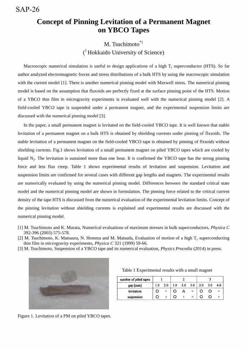
In the paper, a small permanent magnet is levitated on the field-cooled YBCO tape. It is well known that stable
levitation of a permanent magnet on a bulk HTS is obtained by shielding currents under pinning of flxsoids. The
stable levitation of a permanent magnet on the field-cooled YBCO tape is obtained by pinning of flxsoids without
shielding currents. Fig.1 shows levitation of a small permanent magnet on piled YBCO tapes which are cooled by
liquid N2. The levitation is sustained more than one hour. It is confirmed the YBCO tape has the strong pinning
force and less flux creep. Table 1 shows experimental results of levitation and suspension. Levitation and
suspension limits are confirmed for several cases with different gap lengths and magnets. The experimental results
are numerically evaluated by using the numerical pinning model. Differences between the standard critical state
model and the numerical pinning model are shown in formulation. The pinning force related to the critical current
density of the tape HTS is discussed from the numerical evaluation of the experimental levitation limits. Concept of
the pinning levitation without shielding currents is explained and experimental results are discussed with the
numerical pinning model.
[1] M. Tsuchimoto and K. Murata, Numerical evaluations of maximum stresses in bulk superconductors, Physica C
392-396 (2003) 575-578.
[2] M. Tsuchimoto, K. Matsuura, N. Homma and M. Matsuda, Evaluation of motion of a high Tc superconducting
thin film in microgravity experiments, Physica C 321 (1999) 59-66.
[3] M. Tsuchimoto, Suspension of a YBCO tape and its numerical evaluation, Physics Procedia (2014) in press.
Table 1 Experimental results with a small magnet
Figure 1. Levitation of a PM on piled YBCO tapes.
SAP-26

Relationship between Magnetic Flux Distribution and Rotational Characteristics in the HTS-Permanent Magnet Hybrid Bearing
Using Attractive Force
K. Oguni*, S. Sakai, S. Ohashi
(Kansai University)
We have developed the hybrid magnetic bearing using permanent magnets and the high temperature bulk super conductor (HTS). In this system, the two pole permanent magnet is installed in the rotor. By this two pole configuration, linkage flux of the permanent magnet into the HTS increases compared with conventional one.
Fig.1 shows the flux for the vertical direction (z). x is defined as the distance from the center of the rotor in the guidance direction. The permanent magnet has ring type structure and the permanent magnet and the HTS is set inside the permanent magnet of the stator. The pinning force of the HTS is used to generate levitation and guidance force. Repulsive force of the permanent magnets was used in the previous hybrid system. However the restoring force in the guidance direction of the conventional hybrid system decreases by the side slip force of the permanent magnets. In this research, attractive force of permanent magnets is introduced to increase the restoring force in the guidance direction. Thus stability in the guidance direction of the hybrid system becomes larger than non-hybrid one. In this paper, influence of the hybrid system on the dynamic characteristics of the rotor is studied. Three-dimensional numerical analysis of the flux in the HTS is undertaken. The relationship between the dynamic characteristics of the hybrid magnetic bearing system and linkage flux of the HTS is considered by the experimental results.
When the rotor of the hybrid magnetic bearing is rotated, the vibration and the gradient angle of the rotor are measured until the rotor reaches to the resonance state. The relationship between the dynamic characteristics of the rotor and the flux inside HTS is considered. And dynamic characteristics of the hybrid system is compared with that of the non-hybrid one. In the hybrid system, the stator side permanent magnet increases the linkage flux of the levitation direction. g is defined as the distance from the top of the HTS to the bottom of the rotor. In the hybrid system the linkage flux of the levitation becomes 2.50 , 1.14 , 1.56 and 5.62% larger at g = 6 , 8 , 10 and 12[mm] respectively than that of the non-hybrid one. The rotor in the hybrid system is supported by the pinning force and attractive force of the permanent magnet. The restoring force in the guidance direction of the hybrid system becomes larger than that of the non-hybrid one because of increment of the linkage flux in the levitation direction. Therefore, in the hybrid system, gradient angle of rotor axis becomes smaller than that of the non-hybrid one.
Fig.1 The magnetic flux generated by the permanent magnet of the rotor
-40 -20 0 20 40-0.8
-0.4
0
0.4
0.8
Distance x [mm]
Mag
neti
c fl
ux d
ensi
ty B
z [T
] z = 0 z = 5[mm] z = 10[mm]
SAP-27

Numerical Study to Obtain the Improved Field Homogeneity and Enlarged Inner Diameter of HTS Bulk Magnet
for Compact NMR
D. Miyazawa*1
, S.B. Kim1, H. Kitamura
1, D. Ishizuka
1, K. Hojo
1
(1Division of Electronic and Information Systems Engineering, Graduate School of
Natural Science and Technology, Okayama University)
We have been studying the compact magnet for NMR device that consists of a stacked high temperature
superconducting (HTS) GdBCO bulk annuli trapped by a field cooling (FC) method. It was difficult to trap the
uniform magnetic field above 4.7 T (200 MHz-class NMR magnet) and field homogeneity under 0.01 ppm/cm3 at
liquid nitrogen temperature (77.4 K) because of the low Jc-B characteristics of present HTS bulks. On the other
hand, the strength and homogeneity of the magnetic field required for NMR relaxometry device are 1.5 T and 150
ppm/cm3 respectively. Therefore, we proposed and developed the compact magnet for NMR relaxometry device.
We can easily generate the trapped magnetic field over 1.5 T at 77.4 K using the stacked HTS bulks, but it is still
hard to obtain 150 ppm/cm3 field homogeneity with the conventional superconducting magnets as the magnetizing
magnets. In our previous works, we could generate the trapped magnetic field over 1.5 T at 77.4 K using the
stacked HTS bulks with 80 mm height, and 150 ppm/cm3 field homogeneity was obtained using the fabricated field
compensate methods on inner diameter of 20 mm HTS bulks. However, it is necessary to enlarge the inner diameter
of HTS bulk magnet because the diameter of the commercial NMR probe is larger than 20 mm. In this paper, we
studied an optimal shape of the stacked HTS bulk magnet to obtain an enlarged inner diameter using 3-D FEM
based analysis, and optimized shape of HTS bulk magnet with enlarged inner diameter over 40 mm when the outer
diameter was fixed by 60 mm will be discussed.
SAP-28

The Dynamic Characteristics on the Wall Traveling of the HTS Bulk Superconducting Actuator
M.Sawae*,1, S.B. Kim1, S.Ozasa1, H.Nakano1, H.Kobayashi1
(1Graduate School of Natural Science and Technology, Okayama
University, 3-1-1, Tsushima-Naka, Kita-ku, Okayama 700-8530, Japan)
The electric device applications of a high temperature superconducting (HTS) bulk having
stable levitation and suspension properties due to their strong flux pinning force have been
proposed and developed. We have been investigating the three-dimensional (3-D)
superconducting actuator using HTS bulk to develop the transportation device with non-contact
and moves in free space. It is expected that our proposed 3-D superconducting actuator to be
useful as a transporter used in clean room which manufactures the silicon wafer where dislikes
mechanical contact and dust. Proposed the actuator consists of a field-cooled HTS bulk for
mover and two-dimensional arranged multiple electromagnets as a stator.
In our previous works, the dynamic characteristics on the floor traveling of the HTS bulk
mover were studied. Therefore in this study, a system for the wall traveling was proposed to
effectively utilize the limited space. It is expected that proposed the wall traveling system is
very useful to apply the transporter used in the tunnels which flammable gas may be produced.
In this paper, the optimal angle between electromagnets located at floor and wall for moving to
the wall traveling from the floor traveling was investigated experimentally. The moving force
comprised of repulsion and guidance forces on the horizontal moving of the HTS bulk and the
position displacement on the rotating of the HTS bulk during the wall traveling were measured.
As a result, the position displacement on the height direction during the rotating of the HTS
bulk was 8 mm from the initial position because its gravity. The detailed experimentally results
will be presented.
SAP-29

The Development of Magnetic Field Control Methods for Magnetic Targeting System using Slit Configuration HTS Bulks.
S. Shima 1,
*,S.B. Kim 1,T. Abe
1,I. Eritate 1,N.Yabe
1,N.Sanada 1
( 1
Graduate School of Natural Science and Technology, Okayama University, 3-1-1,
Tsushima Naka, Kita-ku, Okayama 700-8530, Japan )
The high magnetic fields are useful in analysis/medical equipments and medicine applications such as a culture of
man’s bone or a cell. The necessary of the high strength magnetic fields are increasing in fields of NMR analysis
and medical applications. So, the techniques for magnetic field concentration are very important, and the novel
electromagnets and trapped HTS bulk magnets was fabricated and used in the cell culture and the magnetic drug
delivery system. In general, although the superconducting magnet can generate the high magnetic fields, ON/OFF
magnetic switching is impossible because of its large inductance. Therefore, not only generating of a magnetic field
but also a control of the magnetic field including ON/OFF switching are very important issues. Therefore, we have
studied the control methods of magnetic field using HTS bulks and the perfect diamagnetism by the shield current.
In this study, the magnetic control system which consists of the HTS bulk and magnetic sources were proposed to
achieve the ON/OFF field control and field amplification. The shape of HTS bulk to develop the magnetic control
system was optimized by FEM based analysis and the abilities of its field switching and amplification were
confirmed by experiments. We found that the HTS bulk with slit configuration controlled the applied magnetic field,
and the amplified magnetic fields were obtained at the slit part of the HTS bulk. For better improvement of field
amplification, the iron block was inserted into the slit part in HTS bulk. The optimal shapes of the slit and the iron
block were designed and tested, and the detail analytical and experimental results will be presented.
SAP-30

ISS-2014
The Study on the Rotation Properties of the Non-Contact Rotating System
Using HTS Bulks and Permanent Magnets
K. Nakamura1
, S.B. Kim1, Y.Fujii
1, T.Tachibana
1
1Division of Electronic and Information Systems Engineering, Okayama University
3-1-1, Tsushima Naka, Kita-ku, Okayama 700-8530, Japan
Non-contact rotating system using magnetic levitation technology doesn’t
have mechanical friction. Therefore, there are advantages like, no energy
loss and maintenance is rarely needed. It is very useful using in vacuum
chamber or clean room where dislike generated dust. For these reasons, a lot
of researches about non-contact levitation technology using electrostatic
force, pressure, ultrasonic wave, air pressure and magnetic force have been
conducted. Among them, the technology using magnetic force has the
advantages that can generate relatively large levitation force and easy to
handle.
The high temperature superconducting (HTS) bulks which magnetized by
field cooling (FC) method, shows the diamagnetic behavior and pinning effect
at the same time. From our previous study, it is known that our system
using ring-shaped permanent magnets and ring-shaped HTS bulks (ID 20
mm, OD 60 mm and 15 mm height) is very useful to apply to the non-contact
rotating system. Therefore, in this study, we have developed a stator with six
poles to investigate the rotation properties of the system. We obtained the
rotating speed of 720rpm using developed six poles stator and non-contact
levitating system. However, it was found that there were unstable rotating
properties during rotation. Therefore, we have studied about structure
optimization in order to improve the moving stability of the rotating shaft.
The detailed experimental results about structure optimization and moving
stability of the levitated rotating shaft will be presented.
SAP-31

Development of Field Control Method and Basic Design of HTS Magnet for MDDS
A.Nakashima*,1, S.B. Kim1, I. Eritate1, N.Sanada1, T. Abe1, S. Shima1, N.Yabe1,
M. Takahashi1
(1Graduate school of natural science and technology okayama university)
The magnetic drug delivery system (MDDS) is a key technology to reduce the side effects in the medical
applications, and the magnetic force control is a very important issue in MDDS. In general, the high magnetic field
along the axial direction and high magnetic field gradient along the longitudinal direction are very useful for MDDS.
So, we proposed the new magnetic force control system that consists of superconducting magnet, high temperature
superconductors (HTS) bulks or tapes and ferromagnetic substances. In this new system, the shielding currents in
HTS bulks and HTS tapes owing to diamagnetism were used, and we could control the magnetic field gradient along
the longitudinal direction by the arrangement of the HTS bulks, tapes and ferromagnetic substances. In this study,
the stacked GdBCO tapes without stabilizer were used in experiments and electromagnetic analysis based on finite
element method (FEM) was carried out to optimize the arrangement of the superconductors and ferromagnetic
substances. We have found the method to control the magnetic field gradient along the longitudinal direction, and
the magnetic field higher than the applied magnetic field was obtained by the proposed control method.
In addition, the multiple racetrack HTS magnets were proposed and designed in order to generate the high field
gradient along the longitudinal direction. The optimized shape of multiple racetrack HTS magnets will be presented.
SAP-32

The Study on The Shape of 2-D Stator with Electromagnets and Permanent Magnets for 3-D Superconducting Actuator
S.Ozasa *1
, S.B.Kim1, H.Nakano
1, M.Sawae
1, H.Kobayashi
1
(1Graduate School of Natural Science and Technology, Okayama University
3-1-1, Tsushima Naka, Okayama 700-8530, Japan)
The electric device applications of a high temperature superconducting (HTS) bulk having stable levitation and
suspension properties due to their strong flux pinning force have been proposed and developed. We have been
investigating a three-dimensional (3-D) superconducting actuator using HTS bulk to develop the transportation
device with non-contact and moves in free space. It is expected that our proposed 3-D superconducting actuator
will be useful as a transporter used in a space full of combustible gas with fear of ignition and a clean room which
manufactures the silicon wafer where dislikes mechanical contact and dust. Proposed the actuator consists of the
trapped HTS bulk as a mover and two-dimensionally (2-D) arranged electromagnets consisted with iron core and
copper coil as a stator. The HTS bulk is magnetically connected with electromagnets and can be moved the 3-D
directions and rotates without upper side electromagnets and spatial restrictions. The current and the polarity of
each electromagnet are individually controlled by the switching power supply.
Probably, the cost of the manufactory will be increased to install the 2-D arranged electromagnets in a large clean
room because many electromagnets are needed to cover a large area. Therefore, we have been trying to find the
method for reducing the number of electromagnets. In this study, all the electromagnets except for rotation was
replaced in the 2-D arranged permanent magnets, and the current patterns and gap length between permanent
magnets were experimentally investigated to improve the dynamic behaviors of the mover and to reduce the cost of
the manufacturing. The optimized current patterns and gap length between the permanent magnets and/or
electromagnets were obtained and the results will be presented.
SAP-33

Short circuit withstanding capability of 154 kV HTS cable for Jeju project in Korea
Seung Ryul Lee*,1
, Jaeyoung Yoon1, Byeong-Mo Yang
2, Byongjun Lee
3
(1KERI,
2KEPRI,
3Korea University)
Jeju project is the first demonstration to apply DC 80 kV and AC 154 kV HTS cable systems to a live grid in
South Korea. This project started in July 2011, funded by Korea Electric Power Cooperation (KEPCO) and the
Ministry of Trade, Industry and Energy of Republic of Korea. LS cable Ltd. has been developing the HTS cable
systems. The installation location is Hanlim-Geumak AC and DC power systems of Jeju Island in South Korea. DC
HTS cable will be operated in 2015. AC HTS cable will be installed and operated in 2016. It is important to design
specifications considering real power system conditions for a successful application of the HTS cable to a real grid.
This paper proposes a design specification for the short circuit withstanding capability of the 154 kV HTS cable to
apply to Korean power transmission system, from the viewpoint of the power system operation.
[1] S. Echroad, “Superconducting Power Equipment”, EPRI report 1024190, 2012
[2] Shinichi Mukoyama, Masashi Yagi, Hirao Hirata, Mitsuo Suzuki, Shigeo Nagaya, Naoji Kashima, and Yuh
Shiohara, “Development of YBCO High-Tc Superconducting Power Cables”, Furukawa Review, No. 35, 2009
[3] KS C 3405, “154 kV cross-linked polyethylene insulated power cable”
[4] KS C 8331, “Alternative Circuit-Breaker for Extra-High Voltage, High Voltage”
SAP-34

Discrimination of Insulation Defects in HVDC HTS Components by Chaotic Analysis of Partial Discharge
In-jin Seo*,1, Won Choi1 and Ja-yoon Koo1
1Hanyang University, Ansan, Gyeonggi 426-791, Korea
The application of HVDC HTS power system has been considered as one of the promising tool due to its several
technical advantages over the traditional power system such as higher overall efficiency, higher current carrying
capability and lower power losses for long-distance transmission. Therefore, many research institutes have tried to
develop any advanced power components employable to the HVDC grids with higher reliability considering the
diagnosis to avoid the unexpected failures.
Since more than two decades, one of the plausible diagnostic methods for the power components applied to AC
grid, the detection of Partial Discharges (PD) taking place inside the component has been widely investigated. In
this paper, since traditional PD analysis methods for AC power component such as PRPD cannot be employed for
the PD under DC stress, we try to propose a chaotic analysis (CAPD) for the related pattern recognition of the
possible defects inside HVDC HTS power components.
In addition, a novel algorithm based on the pulse shape analysis is suggested, for which design concept are
developed with a view to separating the defects inside the HVDC HTS power component. For the experimental
investigation, several defects have been fabricated considering possible defects formed during the manufacturing
process of power components. And then PDs are produced from them and then detected for the analysis based on
proposed methods. Moreover, the relevant hardware and software are under development for the commercial
purpose.
SAP-35

Natural Circulation of the Liquid Nitrogen in the Cryogenic Pipe of the 200 m DC Superconducting Cable Facility
Yury V. Ivanov*, Hirofumi Watanabe, Noriko Chikumoto, Makoto Hamabe, Jian Sun, Satarou Yamaguchi
(Chubu University, 1200 Matsumoto-cho, Kasugai, Aichi 487-8501, Japan)
The centenary period of research of superconductivity has come to the end with creation of experimental high temperature superconducting power transmission (HTS PT) lines of several hundred meter class. Projects of HTS PT lines of kilometer class which will be established in really operating networks are under construction now. Unfortunately, progress in the field of large-scale application of HTS is restrained by the high cost and complexity of HTS cable cooling systems. Several years ago it was made a proposal to use a thermosiphon effect to keep HTS cable at low temperature. Because a cryogen naturally heats up while flows through the cryogenic channel accumulating heat load, its density changes from point to point. Therefore, if it will be possible to achieve low hydraulic resistance and provide sufficient cryogen level difference a natural circulation will arise. Ideally, HTS PT line may not contain the cryogenic pump. This approach can reduce the cost of apparatus making it more simple and stable. The feasibility of the given approach was confirmed theoretically for various system configurations. Preliminary experiments were also carried out using 200-meter DC HTS facility at Chubu University during 3rd and 4th cooling tests. Recently, during 6th cooling test the cryopump has stopped due to a controller fault. Meanwhile, the natural circulation of the liquid nitrogen was observed at flow rate of about 2 l/min, and the cable temperature remained low.
[1] Ivanov Y., Watanabe H., Hamabe M., Kawahara T., Sun J., Yamaguchi S. Observation of the thermosiphon effect in the circulation of liquid nitrogen in HTS cable cooling system. // Phys. Procedia. (2012) 27 368-371 [2] Yamaguchi S., Kawahara T., Hamabe M., Watanabe H., Ivanov Y., Sun J., Iiyoshi A. Design and construction of 200-meter high temperature superconducting DC power cable test facility in Chubu University. // Proc. 23 Int. Cryog. Eng. Conf. Int. Cryog. Mater. Conf. 2010. (2011) 1041-1047
SAP-36

RTDS-based Development of a Protection System for a 154 kV
HTS AC Power Cable
Minh-Chau Dinh*,1
, Sung-Kyu Kim1, Minwon Park
1, In-Keun Yu
1, Byeongmo Yang
2
(1Changwon National University,
2Korea Electric Power Research Institute)
Various classes of high temperature superconducting (HTS) cable system have been developed and
demonstrated successfully in Korea. In the near future, a commercial version of the HTS power cable is expected to
be installed to a real grid [1]. Like a conventional cable or transmission line, a protection system for an HTS AC
power cable is needed to keep it operating safely and reliably on a utility electrical network [2]. So, before
installing the HTS AC power cable in an actual grid, a protection system for the HTS AC power cable should be
designed and investigated.
This paper presents protective relay system including distance relay and differential relay for the 154 kV HTS
AC power cable. The cable characteristics under fault conditions in the grid such as current sharing between
conducting layer and former, between shield layer and stabilizer layer, and varying cable resistance due to quench
are analyzed. And then, the varying cable impedance according to fault current flowing through the cable and cable
temperature is analyzed and used for its protection system design.
The real time digital simulator (RTDS) offers the most advanced and effective means available for testing
protection systems. Therefore, RTDS-based closed-loop test of a protective relay system was conducted to verify
the designed setting. To serve this purpose, the modeling of a 154 kV test power system and the HTS AC power
cable was implemented in RTDS. A practical relay device was connected in the closed-loop with the power system
modeled in the RTDS.
The results show that the protective relay system with its designed setting operated properly in the application
for the HTS AC power cable.
[1] Cheolhwi Ryu, Hyunman Jang, Changyeol Choi, etc, "Current status of demonstration and
commercialization of HTS cable system in grid in Korea ," 2013 IEEE International Conference on
Applied Superconductivity and Electromagnetic Devices (ASEMD), pp. 539 - 542, Oct. 2013.
[2] Jun Yang, Zhe Zhang, Xianggen Yin, Yuejin Tang, et c, "The development of protection and
monitoring system for high temperature superconducting cable," 39th International Universities Power
Engineering Conference (UPEC 2004), vol. 1, pp. 709-712, Sept. 2004.
SAP-37

Verification through RTDS Test for Thermal Relay Protection Relay
in Icheon Substation HTS Distribution System
Hansang Lee
In order to meet the needs for increasing electrical loads and solve the problems of equipment
expansion, the HTS cable which can transfer large capacity of electric power has been being
proposed as one of the most optimal solutions. Although there have been various types of
researches about HTS cable application to the real grid, especially protection systems against
power system faults, studies about thermal protection for HTS cables has not been progressed
sufficiently. Since the quenching of the HTS cable caused by large magnitude and long
duration of fault current has severe ripple effects, not only electrical protection but also
thermal protection should be considered carefully to secure system operation and to avoid
large economic loss. Based on the proposed algorithm and a RTDS model for thermal relay in
Icheon substation HTS distribution system, thermal relay with user-defined code has been
proposed and the it has been verified using real-time digital simulator(RTDS).
SAP-38

Thermal Characteristics of the Epoxy Insulator in the Stop Joint Box of HTS Power Cable
Sang Yoon Lee*,1, Jong Ho Choi1, Chankyeong Lee1, Seokho Kim1, Kideok Sim2, Jeonwook Cho2, Hyung-Seop Shin3
1 Changwon National University, Changwon, Korea 2 Korea Electrotechnology Research Institue, Changwon, Korea
3 Andong National University, Andong, Korea
The superconducting power cable is cooled by forced circulating liquid nitrogen. As the length of the cable increases, the cooling load of a refrigerator also increases and stop joint boxes are the essential component of a long HTS power cable. The types of joint boxes can be divided into two groups; NJB (Normal Joint Box) and SJB (Stop Joint Box). Generally, liquid nitrogen passes through the joint box in NJB inside the cable cryostat after electrical connection. However, SJB separates each cooling path. In case of a long distance HTS power cable, it is necessary to separate the cooling line per the regular distance of cooling system considering the pressure drop of the liquid nitrogen path. Therefore, SJB is an essential component for the long HTS power cable. However, SJB have some different features from the insulation method of NJB with continuous nitrogen path. SJB should be composed of solid electrical insulation material to block the liquid nitrogen path. The solid electrical insulation structure experiences the extreme thermal stress and thermo-mechanical design of the insulation structure is very important.
In this paper, the optimal shape of SJB and the cooling method are investigated using FEM analysis and experiments with test specimens to reduce the thermal stress and avoid damage from the temperature difference during the cool down process.
[1] Maziar Moradi, Student Member, and Siva Sivoththaman, Senior Member, “Stain Transfer Analysis of Surface-Bonded MEMS Strain Sensors”, IEEE sensors journal, Vol. 13, No.2, (2013), pp.637~643
SAP-39

Feasibility Analysis of a Novel Hybrid-type Superconducting Circuit Breaker in Multi-Terminal HVDC Networks
Umer Amir Khan*,1,2
, Jong-Geon Lee1, Faisal Amir
2, Bang-Wook Lee
1
(1Hanyang University,
2National University of Sciences and Technology)
Voltage Source Converter based HVDC systems (VSC HVDC) are a better alternative than conventional
thyristor based HVDC systems, especially for developing Multi-Terminal HVDC Systems (MTDC). However,
sharp rising time of DC fault current in MTDC due to lower DC line impedance and absence of zero crossing
makes DC fault current interruption extremely difficult. The key obstacle in developing MTDC is absence of
adequate protection system which can quickly detect the fault, locate the faulty line and trip the HVDC Circuit
Breakers (DCCB). DCCBs are needed to prevent the fault current from rising to unbreakable values and break the
DC fault current once trip signal is issued.
In this paper, a novel hybrid-type superconducting circuit breaker (SDCCB) is proposed and feasibility analyses
of its application in MTDC are presented. The SDCCB has a superconducting fault current limiter (SFCL) located in
the main current path to limit the fault current until final trip signal is received. After the trip signal the IGBT located
in the main line commutates the current into a parallel line where DC current is made zero by combination of IGBTs
and surge arresters. Fault simulations for three, four and five terminals MTDC were performed and SDCCB’s
performance was investigated for increasing fault current intensities. It was observed that DCCB in MTDC requires
bidirectional current breaking capability. SDCCB model was modified and its performance was reevaluated for
successfully breaking DC fault current and isolating the faulty HVDC line in MTDC.
Character Count: 1558
SAP-41

Design and study of the stress cone on HTS cable terminal based
on finite element method
K. K. Lu1,2
, J. Fang*,1
, H. J. Zhang2, X. H. Huang
2, M. Qiu
2, S. Li
1, D-X.Chen
3
(1School of Electrical Engineering, Beijing Jiaotong University, Beijing, China;
2China Electric Power Research Institute, Beijing, China
3Departament de Fisica, Universitat Autonoma de Barcelona, 08193 Bellaterra, Barcelona,
Spain)
ABSTRACT
As one of the important components of superconducting cable, superconducting cable terminal can well conduct
the transition between superconducting cable and conventional cable. Aimed at improving the performance of high
temperature superconducting (HTS) cable stress cone, based on design method of the conventional cable stress
cone and the special requirements of HTS cable, we deduce the stress cone analysis model which includes
insulation thickness, the surface, the curvature and the length of the HTS cable stress cone. Then we research the
influence of structure parameters of the stress cone on the electric field distribution. Eventually, the finite-element
simulation software ANSYS is applied to analyze the potential distribution and electric field distribution. The
simulation results of software ANSYS are compared with the results of the analysis model and the validity of the
analysis model is verified. This research will lay a foundation for the further study and design of the HTS cable
terminal.
Key words: HTS cable terminal; The stress cone; Electric field distribution; The curvature parameter
* Corresponding author:
Name: Jin Fang
Postal address: Room 508, Electrical Engineering Building, Beijing Jiaotong University, Beijing, China, 100044
Phone: +86-13911063206
Fax: +86-10-51687101
E-mail: [email protected]
SAP-42
Current of BSCCO Tape in the Stacked Conductors with Active Ferromagnetic Layers under Varying Current Feeding Mode
Hisato Ohara1, Jian Sun*,2, Makoto Hamabe1, Satarou Yamaguchi1,2
(1Department of electrical engineering, Chubu University, Kasugai, 4878501, Japan, 2Center of Applied Superconductivity and Sustainable Energy Research (CASER), Chubu
University, Kasugai, 4878501, Japan)
After the construction of the 200 m high temperature superconducting (HTS) cable test facility at Chubu University in 2010[1], studies on the tape performance in the cable was started by the critical current measurement [2]. In the 200 m cable system, a three-layer structure of the tapes in the cable is employed for obtaining the high current capacity up to 2 kA. Previous study shows that the critical current is affected by the layout of the tapes such as gaps and the current feeding mode [3]. In the stacked tape conductors, the critical current of BSCCO tapes shows strong dependence on the current feeding directions between the tapes. The critical current is improved when the opposite-direction current applied to them and diminished for the same-direction current feeding mode because of strong magnetic field interaction between them. By using the ferromagnetic layers, self-field of HTS tapes will be affected and may improve their critical current. This paper will present the measurements of the critical currents of BSCCO tape in the stacked conductors with the active ferromagnetic layers. Effects on the critical current of HTS tape of the magnetic field from the currents applied to the neighboring tapes and the ferromagnetic layers will be reported through the magnetic field analysis.
[1] S. Yamaguchi, et.al, Physica C: Superconductivity, Vol. 471, pp.1300-1303 (2011).
[2] J. Sun, et. al, Physica C: Superconductivity, Vol. 471, p.1313-1316 (2011).
[3] J. Sun, et. al, Physica C: Superconductivity, Vol. 494, pp.297-301 (2013).
SAP-43

An Action Dependent Heuristic Dynamic Programming-Controlled Superconducting Magnetic Energy Storage for Transient Stability Augmentation
Xinpu Wang1, JunYang
1, Xiaodong Zhang*
,2, Xiaopeng Yu
2
(1School of Electrical Engineering, Wuhan University, Wuhan
430072, Hubei Province, China; 2State Grid Henan Electric Power
Company, Zhengzhou 450052, Henan Province, China) To enhance the stability of power system, the real power can be absorbed or released from
Superconducting magnetic energy storage (SMES) unit according to system power
requirements. This paper presents a control strategy based on action dependent heuristic
dynamic programing (ADHDP) which can control SMES to improve the stability of electric
power system with on-line learning ability. Based on back propagation (BP) neural network,
ADHDP approximates the optimal control solution of nonlinear system through iteration step
by step. By on-line learning the reinforcement signal from the external environment, ADHDP
can automatically adjust the neural network weights according to the back propagation error
to achieve optimal control performance. To investigate the effectiveness of the computational
intelligence control method, simulation tests are carried out in Matlab/Simulink. And a
conventional Proportional-Integral (PI) controlled method is used to compare the performance
of ADHDP. Simulation results show that the proposed controller demonstrates superior
damping performance on power system oscillation over the PI controller.
SAP-44

The Impact of SFCL and SMES Integration on Optimal Reclosing Time of Transmission Lines
JunYang*,1, Xinpu Wang
1, Xiaodong Zhang
2, Xiaopeng Yu
2
(1School of Electrical Engineering, Wuhan University, Wuhan
430072, Hubei Province, China; 2State Grid Henan Electric Power
Company, Zhengzhou 450052, Henan Province, China) After the transmission line is removed for a transitory nature fault, the line may be
reconnected by automatically reclosing the circuit breakers to improve the power supply
continuity. To maintain the synchronism and to enhance the transient stability of the power
system, the circuit breakers should be reclosed at the optimal reclosing time (ORCT). This
paper aims at investigating the impact of the integration of superconducting fault current
limiter (SFCL) and superconducting magnetic energy storage (SMES) on ORCT of
transmission lines. With SFCL, the low voltage ride-through capability of SMES can be
enhanced as well as its MW and MJ capacities. Based on the transient kinetic energy function
under the inertial coordinate system, the optimal reclosing time of an instantaneous fault
occurring in a transmission line including the integration of SFCL and SMES is studied.
Simulation results of a multi-machine power system in Matlab/simulink show that the
influence of the integration of SFCL and SMES on ORCT is favorable.
SAP-45
Novel adaptive distance relay algorithm considering the operation of 154 kV SFCL in Korean power transmission system
Seung Ryul Lee*,1
, Jong-Joo Lee1, Sung-Hwan Song
1, Jea-Young Yoon
1, Byongjun Lee
2
(1KERI,
2Korea University)
In South Korea, a new project for the 154 kV SFCL started in July 2011. When SFCLs are applied to an actual
power system, it is very important to carry out power system studies on the impact of SFCLs to protective relay
systems. In general, SFCLs have a negative impact on the protective coordination in power transmission system
because of the variable impedance of SFCLs. In Korea, distance relays are applied to 154 kV power transmission
systems as the backup protection system. 154 kV SFCL of South Korea may not be applied to real Korean power
system in the worst case because of the impact on the distance relay system. This paper reviews some protection
problems which can be caused by the application of 154 kV SFCLs to power transmission systems in Korea. And
then this paper proposes a novel protection algorithm for a distance relay considering the operation of 154 kV
SFCL in Korean power system. In the proposed algorithm, the distance relay can calculate whether the CLR
(Current Limiting Reactor) of the SFCL system is inserted or not, using the measured voltage and current.
SAP-46
Operation characteristics analysis of a Flux-offset type Fault Current Limiter applied to superconducting element
Hye-Won CHOI*, Hyo-Sang CHOI, Byung-Ik JUNG,
In-Sung JEONG, Min-Sang KANG, Yu-Kyeong LEE
Chosun University
Our research team had proposed a flux-offset type fault current limiter(FCL) as new current limiting device. The
flux-offset type fault current limiter is technology using flux-cancellation between primary and secondary winding of
a transformer. A stable limit characteristic of fault current was checked through previous research. However, Our
research team found the peak value of initial fault current was not limited.
Therefore, In this paper, Flux-offset type fault current limiter was applied to the secondary winding of the
superconducting element. According to the test results, the system performed stably without any impedance, because
the primary and secondary winding fluxes of the transformer offset each other at normal times. But, when an fault
occurs, secondary winding of the transformer applying superconducting element was quenched. Because of this, The
peak value of initial fault current was limited within a half-period. After a half-cycle, secondary winding circuit was
opened, the fault current was effectively limited by the impedance of the primary winding of the transformer. The
power burden of a transformer was more reduced than when high-speed interrupter was applied to secondary winding
of the transformer.
“This research was supported by Basic Science Research Program through the National Research Foundation of
Korea(NRF) funded by the Ministry of Education, Science and Technology (NRF-2013R1A1A2010202)”
SAP-47

Characteristic comparison of peak current limiting in two magnetically coupled SFCLs using dual iron core
Seok-Cheol Koa, Tae-Hee Han
b, Sung-Hun Lim
c*
a. Industry-University Cooperation Foundation, Kongju National University, Chungnam 314-701, Republic of
Korea
b. Department of Materials Science and Engineering, Jungwon University, Chungbuk 367-805, Republic of Korea
c. Department of Electrical Engineering, Soongsil University, Seoul 156-743, Republic of Korea
In this paper, the peak current limiting characteristics of the superconducting fault current limiter (SFCLs) using
dual iron core were compared to each other. Two magnetically coupled SFCLs connected in parallel or series
between two coils. The peak current limiting and the recovery characteristics of these SFCLs can be varied
depending on design conductions such as the winding direction and the inductance ratio between two coils.
Through the fault current limiting and the recovery experiment, the peak current limiting effect and the recovery
characteristics for these SFCLs were definitely explained.
* Corresponding author.
Prof. Sung-Hun Lim
Postal address: Department of Electrical Engineering, Soongsil University, 1-1, Sangdo-5-Dong, Dongjak-Gu,
Seoul 156-743, Korea
Phone: +82-2-828-7268
Fax: +82-2-817-7961
E-mail address: [email protected]
SAP-48

Voltage regulation plan by composing subsystem with the SFES for DC On-Line Electric
S. Jung*1, J. H. Lee1, M. Yoon1, H. Lee2, G. Jang1
(1Korea University, 2Kyungil University)
The study of the application process of the relatively small size ‘Superconducting Flywheel Energy Storage (SFES)’ system is conducted to regulate voltage fluctuation of the DC On-Line Electric Vehicle (OLEV) system, which is designed by using DC power system network. It is recommended to construct the power conversion system nearby the substation because the charging system is under the low voltage. But as the system is usually built around urban area and it makes hard to construct the subsystems at every station, voltage drop can occur in power supply inverter that is some distance from the substation. As the alternative of this issue, DC distribution system is recently introduced and has possibility to solve the above issue. In this paper, SFES is introduced to solve the voltage drop under the low voltage distribution system by using the concept of the proposed DC OLEV which results in building the longer distance power supply system. The simulation to design the SFES by using DC power flow analysis is carried out and it is verified in this paper.
Figure 1. Overview of the SFES operation in design system
SAP-50

Transient Characteristic of Flux-offset type SFCL
Byung-Ik Jung1, Hyo-Sang Choi1, Hye-Won Choi1, In-Sung Jeong1, Min-Sang Kang1, Yu-Kyeong Lee1
(1Chosun University)
Superconducting fault current limiters (SFCLs) were installed for improving its reliability and stability by
decreasing of the fault current in the power system. This paper describes operating performance of flux-offset type
SFCL under the triple line ground fault.
In this system, the superconducting element was connected secondary winding terminal of the transformer in
series. When faults occurred on the power system, superconducting element was quenched and then generated the
impedance by the imbalance flux.
It was confirmed that the SFCL limited the peak fault current from approximately 200 to 40 A, reduced the
power burden of protective device, and successfully recovered to superconducting state.
ACKNOWLEDGMENT
Following are results of a study on the "Leaders in Industry-university Cooperation" Project, supported by the
Ministry of Education, Science & Technology (MEST) and the National Research Foundation of Korea (NRF).
This research was supported by Basic Science Research Program through the National Research Foundation of
Korea(NRF) funded by the Ministry of Education, Science and Technology(2014R1A6A3A01008829).
SAP-51

Application of an improved flux-coupling type superconducting fault current limiter for protection of high-penetration micro-grid
Lei Chen, Feng Zheng*, Changhong Deng
(School of Electrical Engineering, Wuhan University, 430072, Wuhan, China)
In recent years, the power industry is moving towards distributed generation (DG) such as renewable energy
(RE), and one of suggested way of integrating high penetration of DG sources is through micro-grids. A micro-grid
can be considered as a low to medium voltage network of small load clusters with DG sources and storage, and
essentially it is an active distribution network defined as an integrated power delivery system [1]. For the
high-penetration micro-grid, how to effectively limit the fault currents to lower levels and enhance the micro-grid’s
fault ride-through (FRT) capacity under fault conditions can be considered to be the key technical issues. In this
paper, based on our previous researches [2], an improved flux-coupling type superconducting fault current limiter
(SFCL), which absorbs and merges the advantages of resistive and inductive types of FCLs [3], is proposed and
selected to play the role. The structure and principle of the suggested SFCL are presented firstly, and then
considering the operation mode and control strategy of a typical high-penetration micro-grid, the SFCL is designed
to be installed at the micro-grid’s different locations. According to the numerical modeling and simulation in
MATLAB/SIMULINK, it is found that, owing to the coordinated actions among the allocated SFCLs, not only the
fault currents can be suppressed, but also the imitated micro-grid’s operational stability can be enhanced obviously.
[1] Taha S.U., Cagil O., Aladin Z., IEEE Trans. Power Syst., 27 (2012) 1560-1567
[2] L. Chen, Y.J. Tang, Z. Li, L. Ren, J. Shi, S.J. Cheng, IEEE Trans. Appl. Supercond. 20 (2010) 278-286.
[3] S. Messalti, S. Belkhiat, J. Supercond. Novel Magn. 26 (2013) 3009-3015.
YBCO
Sload
Is
M
S1
I2
Us
R
L1
L2Zs
I1
Ir
Ics
moa(a)
R
M
ML1
S load
Is
S1 I1
I2
Us Zs
ML2
Ir
Ics
moa
YBCO
(b)
Figure 1. Structure of the improved flux-coupling type SFCL: (a) main connection, (b) equivalent circuit.
SAP-52

Study on Protection Scheme using SFCL for Transmission system with Thyristor Controlled Series Capacitor
Jae-Sun Huh1*, Woon-Sik Moon1, and Jae-Chul Kim1
(1Soongsil University)
In this paper, we propose a protection scheme using a superconducting fault current limiter (SFCL) for the power
transmission system with Thyristor Controlled Series Capacitor (TCSC). TCSC is one of the Flexible AC
Transmission (FACT) system and can bring effectiveness such as power flow control, increase in transmission
capacity, and improvement for system transient phenomena. TCSC consists of a series capacitor bank shunted by
a thyristor-controlled reactor. Because this has same effect to the reducing series impedances in transmission
system, there are serious problem such as increase in fault current, transient stability deterioration and following
redesign of protection system of grid. The proposed protection scheme using the SFCL can mitigate these problems.
In addition, SFCL can be expected to protect the TCSC from a large transient current generated by lightning or
switching surge in power transmission system. To verify the effect of the proposed protection scheme, the
time-domain transient simulation software PSCAD/EMTDC is used.
Categories : d-7 Large Scale System Applications
SAP-53

Improvement of Voltage Sags through Correction of Protective Devices Considering Application of a SFCL in a Power
Distribution System with a Dispersed Generation
Sung-Hun Lim*1, Jin-Seok Kim1, Jae-Chul Kim1
(1School of Electrical Engineering Soongsil University)
The continuous increase of the dispersed generation (DG) in a power distribution system has been reported to cause the rising short-circuit current. As one of effective methods to reduce the fault current, the superconducting fault current limier (SFCL) has been studied to apply into a power distribution system with the DG. However, the introduction of the SFCL in a power distribution system with the DG is expected to affect the bus voltage commonly connected with a sound line together with the decrease the fault current in a fault line. Especially, since the variation and the duration of the bus voltage sag are closely affected by the amplitude of the fault current as well as the operation of the protective devices, the studies on the application of the SFCL for the effective suppression of the bus voltage sag in a power distribution system linked by a DG are required.
In this paper, the improvement of the bus voltage sag in a power distribution system with the DG where the larger fault current was limited by the SFCL was investigated through the correction of the protective devices considering the application of the SFCL. To verify the improvement of the bus voltage sag through the application of the SFCL, the short-circuit tests for the simulated power distribution system interconnected with a simulated DG, which was protected by the protective devices and the SFCL, were performed. Through the estimation using the information of technology industry council (ITIC) curve, which is most generally used for voltage sag estimation, the improved suppressing effect of the bus voltage sag could be obtained.
SAP-54

Peak Current Limiting and Recovery Characteristics of Autotransformer Type SFCL with Adjustable
Triggered Current Level
Seok-Cheol Ko1, Tae-Hee Han2, Sung-Hun Lim*3
(1Kongju National University, 2Jungwon University, , 3Soongsil University)
The peak current limiting and recovery characteristics of autotransformer type superconducting fault current limiter (SFCL) with adjustable triggered current level, which consists of one winding with tap changer and two superconducting (SC) elements with the inserting resistance, were analyzed. The feature of the suggested SFCL is that the triggered current level of the SFCL can be adjusted with its tap changer installed in the autotransformer’s winding comprising the SFCL and that it can limit the fault current by triggering either one SC element or two SC elements comprising the SFCL depending on the transient component’s amplitude of the initial fault current.
As the influential design parameter to affect the triggered current level and the limiting impedance of the SFCL, the coupling coefficient, which depends on the location of its tap changer on the winding of the transformer, was selected and, from its electrical equivalent circuit considering the coupling coefficient, the triggered current level and the limiting impedance of the SFCL were derived and the correlation between two derived SFCL’s design parameters was analyzed.
Through the analysis on the short-circuit tests for the autotransformer type SFCL with the different coupling coefficients, the available peak current limiting and the recovery characteristics of the suggested SFCL were described.
SAP-55

Detection and Protection system for normal transitions in a Single-phase High Temperature Superconducting Transformer by
Using the Active Power Method
N.Nanato, Y.Kobayashi*, N.Koide, S.Nakamura, N.Kishi
(Department of Electrical and Electronic Engineering, Division of Industrial Innovation
Sciences, Graduate School of Natural Science and Technology, Okayama University
3-1-1 Tsushima Naka, Kita-ku, Okayama, 700-8530, Japan)
High temperature superconducting (HTS) wires with good characteristics have been developed in recent years
and commercial HTS wires have large critical current of over 200 A/mm2. Measurement of current conduction
characteristics is essential for practical use of HTS equipment which consists of the HTS wires with such large
critical currents. Then power sources which can supply the current of over 200 A are needed for the measurement.
However, general power supplies especially for AC current sources have large size and weight and therefore
convenience of the power supplies are insufficient. The presenters have developed a small, light and highly
efficient AC power supply with a single-phase HTS transformer which has capacity of 1.5 kW and can supply 300
A current from its secondary coil. In this presentation, detection and protection system for normal transitions in the
HTS transformer is presented. The system is needed to simultaneously monitor its primary and secondary coils.
The presenter constructed the system by the active power method [1, 2]. This presentation shows that the system
can detect the normal transitions and protect the HTS transformer.
[1] Nozomu Nanato, Takahiro Inoue, Satoru Murase, Gen Nishijima, Katsunori Tamakawa, Munenori Amaya,
Yoshifumi Uemura : Quench protection tests of a cryocooler cooled 6 T NbTi superconducting magnet by an active
power method, Cryogenics, Vol. 52/7-9, pp. 321-324 (2012)
[2] N.Nanato, Y.Kobayashi : Quench Detection and Protection for High Temperature Superconducting
Transformers by Using the Active Power Method, Physics Procedia, printed
(a) AC power supply with superconducting (b) Detection of normal transition
transformer for large AC current
Figure 1. Overview of Superconducting Transformer and Test Result
SAP-56

Comparison of Application Characteristics of Superconducting Fault Current Limiter both for LCC-HVDC and VSC-HVDC
Systems
Jong Geon Lee*1, Umer Amir Khan
1, Jung-Ho Kim
1, Bang-Wook Lee
1
(1Hanyang University)
Recently, HVDC system has been evaluated as the optimum solution for the renewable energy transmission and
long-distance power grid connections. In spite of the various advantages of HVDC system, it still has been regarded
as an unreliable system compared to AC system due to its vulnerable characteristics on the power system fault.
Furthermore, unlike AC system, optimum protection and switching device has not been fully developed yet .
Therefore, in order to enhance the reliability of the HVDC systems mitigation of power system fault and reliable fault
current limiting and switching devices should be developed.
In this paper, in order to find suitable solution for HVDC system fault both for Line Commutated
Converter(LCC)-HVDC and Voltage Source Converter(VSC)-HVDC system, the application of resistive
superconducting fault current limiter which has been known as optimum solution to cope with the power system fault
was considered. Firstly, simulation models for two types of LCC-HVDC and VSC-HVDC system which has point to
point connection model were developed. From the designed model, V-I characteristics of faulty condition were
analyzed. Second, application of SFCL on each types of HVDC system and investigation of modified V-I
characteristics were progressed. From the investigated result, the performance comparison when the SFCL applied
on LCC-HVDC and VSC-HVDC was performed.
SAP-57

Operating Characteristic Investigation of a 400 mH class HTS DC Reactor in Connection with a Laboratory Scale LCC type HVDC
System
Sung-Kyu Kim*,1
, Kwangmin Kim1, Minwon Park
1, In-Keun Yu
1, Sangjin Lee
2
(1Changwon National University([email protected]),
2Uiduk University)
High temperature superconducting (HTS) devices including HTS power cable, superconducting fault current
limiter, and superconducting magnetic energy storage system are being developed to make use of their advantages
[1,2]. High voltage direct current (HVDC) transmission systems need large capacity of DC reactor; however
general copper winding reactors cause a lot of electrical losses and difficulties in making large inductance. So, it is
being attempted to apply the HTS devices such as HTS power cable and HTS reactor to a HVDC transmission
system [2]. It should be examined in advance under a real system environment.
The authors have developed a 400 mH class HTS DC reactor and a laboratory scale line-commutated converter
type HVDC system. The HTS DC reactor was connected to the HVDC system to examine the operating
characteristics of the HTS DC reactor in the system. The 400 mH class toroid-type HTS DC reactor is designed
using 32 D-shape double pancake coils. The HVDC system is a mono-pole system and composed of 12
thyristors-based power converters, transformers, AC and DC reactors.
In this paper, the investigation results of the HTS DC reactor and the HVDC system are described. The operating
characteristics of the HTS DC reactor are analyzed under various operating conditions of the system. Through the
results, applicability of an HTS DC reactor in a HVDC system is discussed in detail.
[1] J. Cho, K. D. Sim, J. H. Bae, H. J. Kim, J. H. Kim, K. C. Seong, H. M. Jang, C. Y. Lee, and D. Y. Koh, “Design
and experimental results of a 3 phase 30 m HTS power cable”, IEEE Trans. Appl. Supercond., vol. 16, pp.
1602-1605, Jun. 2006.
[2] T. Hamajima, N. Hu, H. Ozcivan, S. Soeda, T. Yagai, and M. Tsuda, “Balanced three-phase distributions of
tri-axial cable for transmission line”, IEEE Trans. Appl. Supercond., vol. 19, pp. 1748-1751, Jun. 2009.
[3] Y.J. Won, J.G. Kim, A.R. Kim, G.H. Kim, M. Park, I.K.Yu, K.D. Sim, J. Cho, S. Lee, K.W. Jeong, K. Watanabe,
“Power system analysis of Hanlim superconducting HVDC system using real time digital simulator”, Physica C,
vol. 471, pp. 1290-1294, 2011.
SAP-58

A Novel Design of a 400 mH 1,500 A class
toroid-type HTS DC Reactor
K. Kim*1, B. S. Go
1, M. Park
1, I. K. Yu
1
(1Chanwon National University([email protected]))
Large electric power systems, such as High Voltage Direct Current (HVDC) transmission systems, require
reactors that have large inductance and high transport current. A DC reactor is operated under DC current to reduce
the current’s ripple or harmonics in the power system. General DC reactors in HVDC systems use a metal
conductor. This has some disadvantages such as massive reactor size, leakage flux, wide install space, heavy
weight, and electrical losses due to the large operating current.
The authors propose a toroid-type High-Temperature Superconductor (HTS) DC reactor as a key technology to
diminish disadvantages associated with general DC reactors. HTS has zero electric resistance under DC current
conditions. It is possible to increase the capacity of the transport current, reduce the reactor’s size, weight and
reduce the electrical losses as well. From the flux leakage point of view, the toroid-type magnet is an ideal structure.
The toroid-type HTS magnet has a much lower leakage flux compared to a solenoid-type HTS magnet because
most magnetic flux line patterns are formed by the shape of the toroid magnet. Therefore, the installation space can
be decreased with the toroid-type HTS DC reactor [1]-[3].
In this paper, a novel design of a toroid-type HTS DC reactor was investigated. The toroid-type HTS magnet for
a DC reactor system was designed using layered 12 mm GdBCO 2G HTS wire. The magnetic field and the
mechanical stress of the toroid-type HTS DC reactor magnet were analyzed using the Finite Element Method (FEM)
program. The goals of the HTS DC reactor in terms of target inductance and current level were 400 mH and 1,500
A, respectively. The expected operating temperature was under 30 K maintained by using conduction cooling
system. These fundamental data will usefully be applied to design a real toroid-type HTS DC reactor.
[1] S. M. Schoenung, W. R. Meier, and W. J. Schafer, “A comparson of large-scale toroidal and solenoidal SMES
systems,” IEEE Transactions on magnetics, vol. 27, pp. 2324-2328, 1991.
[2] S. Lee, W. S. Kim, S. H. Park, J. W. Lee, C. Park, J. H. Bae, K. C. Seoung, H. Lee, J. H. Lee, K. Choi, and S.
Hahn, “Design of HTS modular magnets for a 2.5 MJ toroidal SMES : ReBCO vs BSCCO,” IEEE
Transactions on Applied Superconductivity, vol. 20, no. 3, pp. 1324-1328, 2010.
[3] D. W. Lieurance, “Global cost optimization of 1-10 MWh toroidal SMES,” IEEE Transactions on Applied
Superconductivity, vol. 7, no. 1, pp. 14-17, 1997.
ACKNOWLEDGMENT
This work was supported by the Power Generation & Electricity Delivery Core Technology Program of the Korea
Institute of Energy Technology Evaluation and Planning (KETEP) granted financial resource from the Ministry of
Trade, Industry & Energy, Republic of Korea.
SAP-59

Stress Analysis and Bobbin Structure Optimization Design for 35kV High Temperature Superconducting Controllable Reactor
Z.Wang*1, L.Ren1,M.Song2, S.Shen1
(1State Key Lab of Advanced Electromagnetic Engineering and Technology 2 Yunnan Electric Power Research Institute)
Abstract: A 35kV high temperature superconducting controllable reactor (HTS-CR) is under development in
China and the electromagnetic design has been completed. Due to the large magnetic flux leakage, Lorentz force of
HTS coils can be so strong and the stress analysis should be carried out to verify that the maximum stress and strain
under different operating conditions is in appropriate range. Stress and strain analysis for the bobbin and its
supporting parts is important for a design a mechanically stable structure. In addition, the thermal stress caused by
AC loss will impact the bobbin and insulation structure of the HTS coils which will endanger the safety of the
35kV HTS-CR. This paper describes an analysis and optimization design result for the bobbin and insulation
structure considering the safety and cooling requirements.
Keywords: stress analysis, bobbin structure, optimization design
SAP-60

Cryogenic Cooling System for 5 kA, 200 µH Class HTS DC Reactor
H. Park*,1
, S. Kim1, K. Kim
1, M. Park
1, T. Park
2, A. Kim
2, S. Lee
3
(1Changwon National University,
2Research Institute of Industrial & Technology,
3Uiduk
University)
DC reactors, made by aluminum busbar, are used to stabilize the arc of an electric furnace. In the conventional
arc furnace, the transport current is several tens of kilo-amperes and enormous resistive loss is generated. To reduce
the resistive loss at the DC reactor, a HTS DC reactor can be considered. It can dramatically improve the electric
efficiency as well as reduce the installation space. Similar with other superconducting equipments, the HTS DC
reactor require current leads from a power source in room temperature to the HTS coil in cryogenic environment.
The heat loss at the metal current leads can be minimized through optimization process considering the geometry
and the transport current. However, the transport current of the HTS DC reactor for the arc furnace is much larger
than most of HTS magnets and the enormous heat penetration through the current lead should be effectively
removed to keep the temperature around 70~77 K. Current leads are cooled down by circulation of liquid nitrogen
from the cooling system with a stirling cryocooler. The operating temperature of HTS coil is 30~40 K and
circulation of gaseous helium is used to remove the heat generation at the HTS coil. Gaseous helium is transported
through the cryogenic helium blower and a single stage GM cryocooler.
This paper describes design and experimental results on the cooling system for current leads and the HTS coil of 5
kA, 200 μH class DC reactor as a prototype. The results are used to verify the design values of the cooling systems
and it will be applied to the design of scale-up cooling system for 50 kA, 200 μH class DC reactor.
[1] H.-M. Chang and S. W. Van Sciver, “Thermodynamic optimization of conduction-cooled HTS current leads,”
Cryogenics, vol. 38, pp.729–736, July 1998.
SAP-61
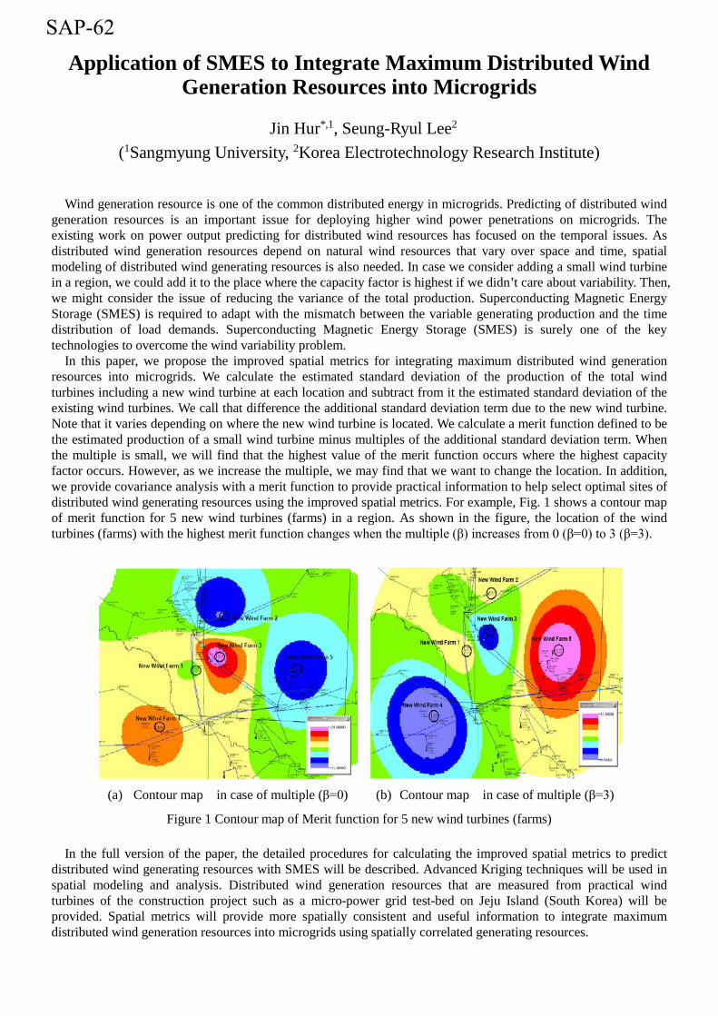
Application of SMES to Integrate Maximum Distributed Wind Generation Resources into Microgrids
Jin Hur*,1, Seung-Ryul Lee2 (1Sangmyung University, 2Korea Electrotechnology Research Institute)
Wind generation resource is one of the common distributed energy in microgrids. Predicting of distributed wind generation resources is an important issue for deploying higher wind power penetrations on microgrids. The existing work on power output predicting for distributed wind resources has focused on the temporal issues. As distributed wind generation resources depend on natural wind resources that vary over space and time, spatial modeling of distributed wind generating resources is also needed. In case we consider adding a small wind turbine in a region, we could add it to the place where the capacity factor is highest if we didn’t care about variability. Then, we might consider the issue of reducing the variance of the total production. Superconducting Magnetic Energy Storage (SMES) is required to adapt with the mismatch between the variable generating production and the time distribution of load demands. Superconducting Magnetic Energy Storage (SMES) is surely one of the key technologies to overcome the wind variability problem.
In this paper, we propose the improved spatial metrics for integrating maximum distributed wind generation resources into microgrids. We calculate the estimated standard deviation of the production of the total wind turbines including a new wind turbine at each location and subtract from it the estimated standard deviation of the existing wind turbines. We call that difference the additional standard deviation term due to the new wind turbine. Note that it varies depending on where the new wind turbine is located. We calculate a merit function defined to be the estimated production of a small wind turbine minus multiples of the additional standard deviation term. When the multiple is small, we will find that the highest value of the merit function occurs where the highest capacity factor occurs. However, as we increase the multiple, we may find that we want to change the location. In addition, we provide covariance analysis with a merit function to provide practical information to help select optimal sites of distributed wind generating resources using the improved spatial metrics. For example, Fig. 1 shows a contour map of merit function for 5 new wind turbines (farms) in a region. As shown in the figure, the location of the wind turbines (farms) with the highest merit function changes when the multiple (β) increases from 0 (β=0) to 3 (β=3).
(a) Contour map in case of multiple (β=0) (b) Contour map in case of multiple (β=3)
Figure 1 Contour map of Merit function for 5 new wind turbines (farms)
In the full version of the paper, the detailed procedures for calculating the improved spatial metrics to predict distributed wind generating resources with SMES will be described. Advanced Kriging techniques will be used in spatial modeling and analysis. Distributed wind generation resources that are measured from practical wind turbines of the construction project such as a micro-power grid test-bed on Jeju Island (South Korea) will be provided. Spatial metrics will provide more spatially consistent and useful information to integrate maximum distributed wind generation resources into microgrids using spatially correlated generating resources.
SAP-62

The Optimization of Racetrack Coil for 12 MW Superconducting Direct-Drive Wind Generator
Lushun Su*,1, Jie He
1,2, Yuejing Tang1,3, Li Ren
1,4, Jingdong Li1,5
(1State Key Laboratory of Advanced Electromagnetic Engineering and Technology, Huazhong University
of Science &Technology, Wuhan, P. R. China)
Due to the high JC of the superconductor, the volume and the weight of the generator can be significantly
reduced if the superconducting coils are used. This paper has designed a 40-pole racetrack excitation coil for the
12MW offshore wind turbines generator. the excitation coil are wound by Nb-Ti superconductor, running at the
temperature of 4.2K. In order to ensure the stability and reliability of the magnetic field, some optimizers for the
design of the excitation coil are adopted. As a result, the fundamental magnetic field at the air-gap center of the
armature coil could reach 2.1T, thereby the 12MW power generation could be achieved.
Figure 1. The former of the racetrack coil.
SAP-63

2 KW High Temperature Superconducting DC Motor
L.F. Bai 1,2, C.S. Li1, P.X. Zhang*,1,2
(1 Northwest Institute for Nonferrous Metal Research, 710016, Xi’an, China, 2 Northwestern Polytechnical University, 710072, Xi’an, China)
This work presents the design and experiment of a small high temperature superconducting DC motor. The high
temperature superconducting tapes are Bi-2223 tapes prepared by powder in tube process. The critical current of
HTS tapes is around 100 A and the length of these tapes is about 200 meters. The motor uses a HTS coil on the
stator and a conventional copper winding on rotor. The HTS solenoid coil is wound with Bi-2223 tapes. The coil is
placed in a cirque stainless steel cryostat and cooled by liquid Nitrogen. The stator iron core is claw pole structure.
A three-dimensional finite element simulation is performed to predict magnetic flux distribution and optimize the
claw pole geometries. The power of motor is 2 KW at 1500 rpm, which shows the best efficiency of 88%. The
efficiency of HTS motor is higher than that of the same power conventional DC motor.
Figure 1. The HTS DC motor.
SAP-64

Influence of primary material on electromagnetic properties of
HTS linear induction motor
B.Liu1, J. Fang
*,1, D-X Chen
2
(1School of Electrical Engineering, Beijing Jiaotong University, Beijing, China;
2Departament de Fisica,Universitat Autonoma de Barcelona,08193
Bellaterra,Barcelona,Spain)
ABSTRACT
High temperature superconductor (HTS) linear induction motor (LIM) with a new material amorphous alloy as
the primary material is designed and analyzed as a prototype to ensure applicability aimed at railway traffic. The
HTS LIM with new material is analyzed by using Ansoft to get magnetic field distribution, thrust force, vertical
force , synchronous speed and AC losses. The critical current of motor and the electromagnetic force are mostly
decided by the leakage flux density of primary slot and by the main magnetic flux and eddy current respectively.
The primary material of motor has a great influence on the distribution of magnetic field, thrust force, vertical force,
synchronous speed, critical current and AC losses. The properties of motor with different primary material, such as
the maximum slot leakage flux density, main flux density, motor thrust and motor vertical force, are analyzed. It
demonstrated that HTS LIM with amorphous alloy as the primary material has better performance and higher
efficiency than HTS LIM with silicon steel as the primary material.
Keywords: HTS LIM, amorphous alloy, primary material, electromagnetic force
* Corresponding author: Fang Jin
Postal address: Room 508, Electrical Engineering Building, Beijing Jiaotong University, Beijing, China,
100044
Phone: +86-13911063206
Fax: +86-10-51687101
E-mail: [email protected]
SAP-65
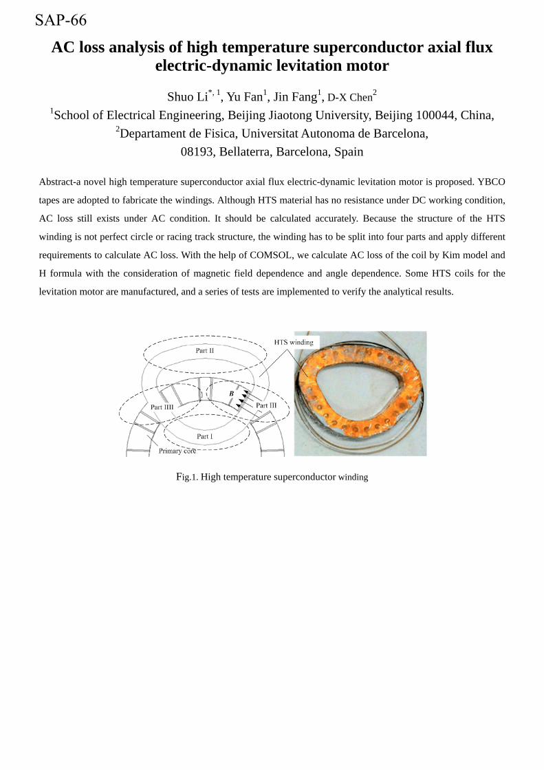
AC loss analysis of high temperature superconductor axial flux electric-dynamic levitation motor
Shuo Li*, 1, Yu Fan1, Jin Fang1, D-X Chen2
1School of Electrical Engineering, Beijing Jiaotong University, Beijing 100044, China, 2Departament de Fisica, Universitat Autonoma de Barcelona,
08193, Bellaterra, Barcelona, Spain
Abstract-a novel high temperature superconductor axial flux electric-dynamic levitation motor is proposed. YBCO
tapes are adopted to fabricate the windings. Although HTS material has no resistance under DC working condition,
AC loss still exists under AC condition. It should be calculated accurately. Because the structure of the HTS
winding is not perfect circle or racing track structure, the winding has to be split into four parts and apply different
requirements to calculate AC loss. With the help of COMSOL, we calculate AC loss of the coil by Kim model and
H formula with the consideration of magnetic field dependence and angle dependence. Some HTS coils for the
levitation motor are manufactured, and a series of tests are implemented to verify the analytical results.
Fig.1. High temperature superconductor winding
SAP-66
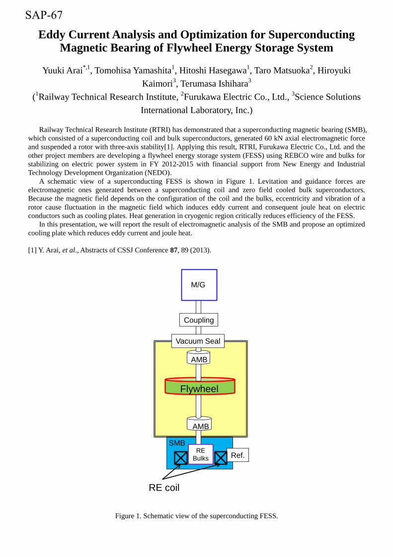
Eddy Current Analysis and Optimization for Superconducting Magnetic Bearing of Flywheel Energy Storage System
Yuuki Arai*,1
, Tomohisa Yamashita1, Hitoshi Hasegawa
1, Taro Matsuoka
2, Hiroyuki
Kaimori3, Terumasa Ishihara
3
(1Railway Technical Research Institute,
2Furukawa Electric Co., Ltd.,
3Science Solutions
International Laboratory, Inc.)
Railway Technical Research Institute (RTRI) has demonstrated that a superconducting magnetic bearing (SMB),
which consisted of a superconducting coil and bulk superconductors, generated 60 kN axial electromagnetic force
and suspended a rotor with three-axis stability[1]. Applying this result, RTRI, Furukawa Electric Co., Ltd. and the
other project members are developing a flywheel energy storage system (FESS) using REBCO wire and bulks for
stabilizing on electric power system in FY 2012-2015 with financial support from New Energy and Industrial
Technology Development Organization (NEDO).
A schematic view of a superconducting FESS is shown in Figure 1. Levitation and guidance forces are
electromagnetic ones generated between a superconducting coil and zero field cooled bulk superconductors.
Because the magnetic field depends on the configuration of the coil and the bulks, eccentricity and vibration of a
rotor cause fluctuation in the magnetic field which induces eddy current and consequent joule heat on electric
conductors such as cooling plates. Heat generation in cryogenic region critically reduces efficiency of the FESS.
In this presentation, we will report the result of electromagnetic analysis of the SMB and propose an optimized
cooling plate which reduces eddy current and joule heat.
[1] Y. Arai, et al., Abstracts of CSSJ Conference 87, 89 (2013).
Figure 1. Schematic view of the superconducting FESS.
SMB
Ref.RE
Bulks
AMB
AMB
Vacuum Seal
Coupling
M/G
Flywheel
RE coil
SAP-67

Design and analysis for SFCL combined system utilizing On-Line Electric Vehicle
S. Jung*1, G. Jang1
(1Korea University)
The various concepts of the wireless power transportation system have been already studied including the efficiency and harmonics issue as well as system stability. This paper deals with a utilizing process about Superconducting Fault Current Limiter (SFCL) at the distribution level to prepare the fault condition of the nearby system with On-Line Electric Vehicle (OLEV), which is designed using the resonance support system. These inductive power conversion system is being considered to build closely to utility grid because the charging system could generate low voltage condition. Therefore, adoption of the current limiter on the system can be a possible solution to the terminal distribution system. Furthermore, the OLEV system utilize resonance charging system which can respond fault condition immediately with segregated state. In this paper, combined SFCL system is introduced to solve the fault current issue under the low voltage distribution system by using the concept of the proposed OLEV and SFCL. The algorithm for the charging system of electric vehicles has been set for the examination of several operating condition, including default status.
Figure 1 Concept of the SFCL application using OLEV
SAP-68
Investigation on Prototype Superconducting Linear Synchronous Motor (LSM) for 600-km/h Wheel-Type Railway
Beomyong Eom*,1
, Changhyeong Lee 1, Changyoung Lee
2, Sangwon Yun
3, Seokho Kim
1
(1Changwon National University, Changwon, Korea,
2Korea Railroad Research Institute,
Uiwang, Korea, 3SuNAM, Anseong, Korea)
The existing wheel-type high-speed railway with a rotatable motor has a limit of 600 km/h speed. The normal
conducting electromagnet has several disadvantages to realize 600 km/h speed. Several disadvantages are the
increased space and weight, and the decreased electric efficiency to generate the required high magnetic field. In
order to reduce the volume and weight, superconducting electromagnets can be considered for LSM (Linear
Synchronous Motor).
Prior to the fabrication of the real system, a prototype demo-coil is designed and fabricated using 2G high
temperature superconducting wire. The prototype HTS coil is cooled by the conduction using a GM cryocooler. To
reduce the heat penetration, thermal design was performed for the current leads, supporting structure and radiation
shield considering the thermal stress. The operating temperature and current is 30~40 K and 100 A. The coil consists
of two double pancake coils (N, S pole, respectively) and it is driven on a test rail installed in the test car.
This paper describes the design and test results of the prototype HTS LSM system. Thermal characteristics are
investigated with additional dummy thermal mass on the coil after turning off the cryocooler.
[1] Chang Young Lee,” Conceptual Design of Superconducting Linear Synchronous Motor for 600-km/h
Wheel-Type Railway”, IEEE transactions on applied superconductivity : a publication of the IEEE
Superconductivity Committee , v.24 no.3, pp.1-4, June 2014.
[2] J. Kluhspies, “Prospects and limitations of high-speed Maglev systems : Aspects of an interdisciplinary
approach”, in Proc. 20th Conf. Magnet. Levitated Syst. Linear Drives, San Diego, 2008, no. 139
[3] K. Nemoto, M. Terai, M. Igarashi, T. Okutomi, S. Hirano, and K. Kuwano, “HTS magnet for Maglev
application (2)-magnet structure and performance”, IEEE Trans. Appl. Supercond., vol.16, no. 2, pp. 1104-1107,
Jun. 2006.
SAP-70

Conceptual Design of High-Tc Superconducting electromagnet for Linear Synchronous Motor for 600km/h Wheel-Type Railway
Changyoung Lee1,2*
, Chanbae Park1, Jinho Lee
1, Yan Son
2, Seokho Kim
3, Yoondo Chung
4,
Sangwon Yoon5
(1Korea Railroad Research Institute,
2University of Science and Technology(UST),
3Changwon National University,
4Suwon Science College,
5SuNAM Co. Ltd)
Authors have studied a 600 km/h wheel-type railway that utilizes the superconducting linear synchronous motor (LSM) as its propulsion system [1]. Conceptual design of the LSM and the train system were introduced in our previous research [2]. The LSM model is designed to be a coreless type, which adopts high-Tc superconducting (HTS) electromagnet as the field magnet on vehicle. This study focuses on the design feasibility of High-Tc superconducting (HTS) electromagnet when it uses a commercially available YBCO HTS wire as the coil winding material. The HTS electromagnet model consists of four-racetrack HTS coils, of which magneto-motive force is designed to be 800kAt from the requirements of LSM. From the mechanical and magnetic stress analysis for the coil, the YBCO wire used is proven to be mechanically robust in the LSM. The simulations for persistent-current mode of the coil show that the improvement of the YBCO wire in the piece length and joint resistance is still necessary. In order to demonstrate YBCO HTS electromagnet, A prototype electromagnet with 2-pole was fabricated and tested in small-scale LSM system. And finally, a few considerations to successfully adopt YBCO wire to LSM for 600km/h wheel-type railway are suggested in this study.
[1] J. F. Gieras and Z. J. Piech, Linear Synchronous Motors-Transportation and Automation Systems, CRC Press,
New York, 2000, pp.103-107.
[2] C.Y. Lee, J.H. Lee, J.M. Jo, C.B. Park, W.H. Ryu, Y.D. Chung, Y.J. Hwang, T.K Ko, S.Y. Oh, J. Lee,
“Conceptual Design of Superconducting Linear Synchronous Motor for 600 km/h Wheel-Type Railway”, IEEE
Trans. Appl. Supercond., vol.24, No. 3, pp. 3600304, June, 2014
Figure 1. Prototype 2-pole High-Tc superconducting electromagnet for small-scale LSM.
SAP-71

Study on Increase of Limiting Capacity of SFCL Based on
Normal Transformers
Dong Chul Chung1*, Jin Wook Park1, Yong Sun Cho2, Byung Ik Jung2, and Hyo Sang Choi2
(1Dept. of Electrical Eng. Woosuk University, 2 Dept. of Electrical Eng. Chosun University )
It is important to find the way for increasing the capacity of superconductors in superconducting fault current limiters (SFCLs) in order to apply SFCLs to the real grid. Normally, this can be accomplished using the serial and parallel connection among superconductors. However, there are problems in unbalanced quenches that arise from the physical differences of superconductors. In this paper we propose a new method to induce simultaneous quenches by using the connection between superconductors and the quaternary winding of a transformer in SFCL system, based on normal transformers as shown in Figure 1. Experimental results are reported in terms of current limiting properties, fault voltages and quench characteristics of superconductors in this system.
Figure 1. Conceptual diagram for the proposed SFCL system based on a normal transformer.
SAP-72

Pulsed field magnetization characteristics of a holed superconducting bulk magnet
K. Yokoyama*,1, R. Igarashi2, R. Togasaki2, T. Oka3
(1Ashikaga Institute of Technology, 2Graduate school, Ashikaga Institute of Technology,3Niigata University)
We have proposed a holed superconducting bulk magnet to trap the magnetic field efficiently in the high-performance material excited by pulsed field magnetization. Previously, a single pulsed field was applied varying the amplitude of the magnetic field and temperature was carried out using a GdBCO bulk material with four small holes, and time responses of flux density on the bulk surface and trapped field distributions were measured [1]. The experiment results suggested that there were too many holes. In this paper, we aim to optimize the number and the size of a small hole. After investigating the magnetization characteristics in the original material, a 1-mm-diamter hole is processed and the same experiment is carried out, and the influence of the hole is evaluated.
[1] K. Yokoyama, T. Tsukui, H. Mita, N. Tsubonoya, 26th International Symposium on Superconductivity,
ISS 2013 (2013) SAP-104.
SAP-73
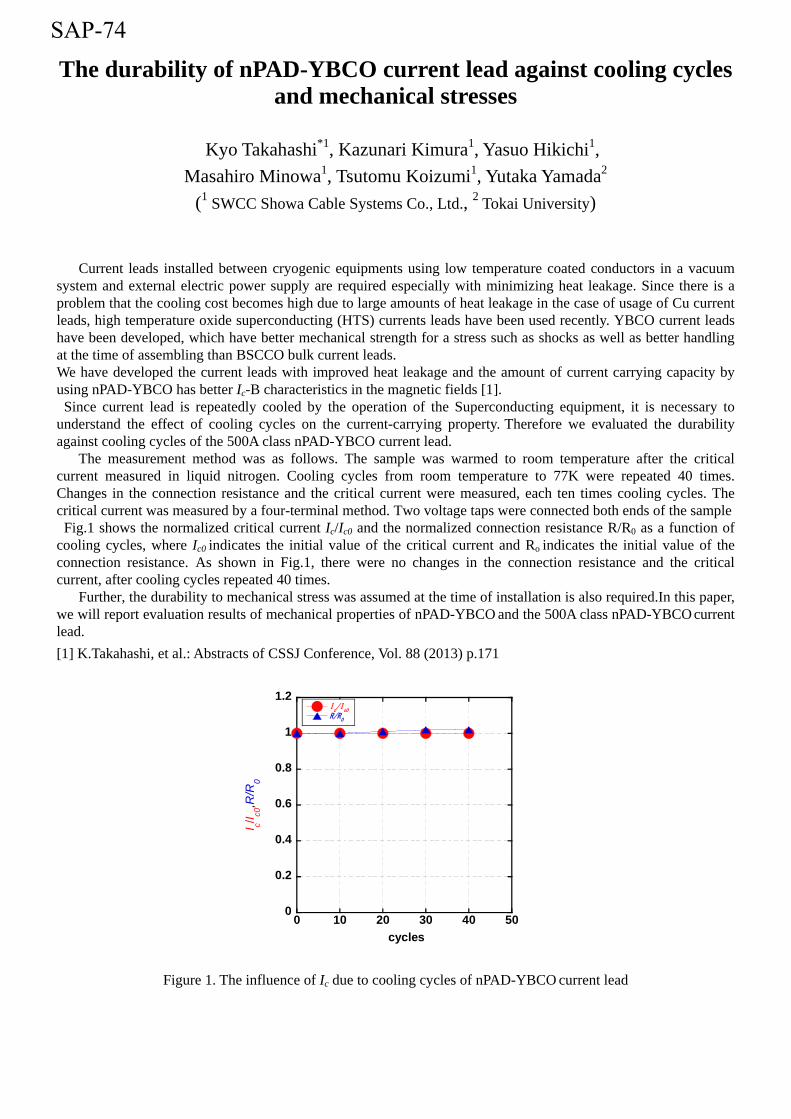
The durability of nPAD-YBCO current lead against cooling cycles and mechanical stresses
Kyo Takahashi*1, Kazunari Kimura1, Yasuo Hikichi1, Masahiro Minowa1, Tsutomu Koizumi1, Yutaka Yamada2
(1 SWCC Showa Cable Systems Co., Ltd., 2 Tokai University)
Current leads installed between cryogenic equipments using low temperature coated conductors in a vacuum system and external electric power supply are required especially with minimizing heat leakage. Since there is a problem that the cooling cost becomes high due to large amounts of heat leakage in the case of usage of Cu current leads, high temperature oxide superconducting (HTS) currents leads have been used recently. YBCO current leads have been developed, which have better mechanical strength for a stress such as shocks as well as better handling at the time of assembling than BSCCO bulk current leads. We have developed the current leads with improved heat leakage and the amount of current carrying capacity by using nPAD-YBCO has better Ic-B characteristics in the magnetic fields [1].
Since current lead is repeatedly cooled by the operation of the Superconducting equipment, it is necessary to understand the effect of cooling cycles on the current-carrying property. Therefore we evaluated the durability against cooling cycles of the 500A class nPAD-YBCO current lead.
The measurement method was as follows. The sample was warmed to room temperature after the critical current measured in liquid nitrogen. Cooling cycles from room temperature to 77K were repeated 40 times. Changes in the connection resistance and the critical current were measured, each ten times cooling cycles. The critical current was measured by a four-terminal method. Two voltage taps were connected both ends of the sample Fig.1 shows the normalized critical current Ic/Ic0 and the normalized connection resistance R/R0 as a function of cooling cycles, where Ic0 indicates the initial value of the critical current and Ro indicates the initial value of the connection resistance. As shown in Fig.1, there were no changes in the connection resistance and the critical current, after cooling cycles repeated 40 times.
Further, the durability to mechanical stress was assumed at the time of installation is also required.In this paper, we will report evaluation results of mechanical properties of nPAD-YBCO and the 500A class nPAD-YBCO current lead. [1] K.Takahashi, et al.: Abstracts of CSSJ Conference, Vol. 88 (2013) p.171
Figure 1. The influence of Ic due to cooling cycles of nPAD-YBCO current lead
0
0.2
0.4
0.6
0.8
1
1.2
0 10 20 30 40 50
Ic/I
c0
R/R0
I c/I c0,R
/R0
cycles
SAP-74

The operating characteristics on Japan’s first in-grid operation of HTS cable
T. Nakano1, O. Maruyama1, S. Honjo1, M. Watanabe2, T. Masuda2, M.Hirose2, M. Shimoda3, N. Nakamura3, H. Yaguchi3, A. Machida3
(1Tokyo Electric Power Company, 2Sumitomo Electric Industries, LTD, 3MAYEKAWA MFG. CO., LTD)
The high-temperature superconducting (HTS) cable demonstration project had been conducted from FY2007 to FY2013. In this project, Tokyo Electric Power Company, Sumitomo Electric Industries, Ltd and MAYEKAWA MFG. co., LTD had been jointly conducted the in-grid demonstration test of HTS cable system. The objective of this project is to evaluate the safety, reliability and other characteristics of it. The cable structure used in this project is the type of Three-in-One cable. Three cores are housed in a stainless steel double corrugated cryostat, which are double vacuum insulating pipes. As a coolant, sub-cooled liquid nitrogen flows through the gap between the corrugated cryostat and the three cable cores. This structure’s advantage lines in its compactness and reduced heat invasion compared with three single-core HTS cables housed in separate cryostats. The cooling system consists of six refrigerators, two circulation pumps and a reservoir tank as major equipments. Each refrigerator has a capacity of 1.0 kW at 77 K or 0.8 kW at 67 K. The number of operating refrigerators is controlled so that the coolant temperature at the cable inlet is kept between preset temperature +1K and preset temperature -1K.
The HTS cable was connected to a real grid from October 29, 2012 to December 25, 2013. The in-grid operation had continued for more than one year without any accidental interruption of the operation or troubles of the system. As one of the in-grid operation tests, we study the temperature dependence on operating performance of the HTS cable system. Besides, after the in-grid operation, we conducted residual performance tests of the system. It was confirmed that the system had good performance and stability after in-grid operation, but the points to be improved, such as cooling system, were discovered. In the presentation, detail will be discussed.
SAP-75