sandblaster cabinet instruction manual ... point the sandblaster gun at any one or spray on your...
TRANSCRIPT

481 Panet Road Winnipeg, MB R3C 2W7
SANDBLASTER CABINET INSTRUCTION MANUAL
ITEM # 8001312
GENERAL INFORMATION The purpose of this manual is to assist you in operating and maintaining your sandblaster. Please read it carefully as it furnishes information which will help you achieve years of dependable trouble free operation.
WARRANTY-PARTS-SERVICE To obtain prompt, efficient service, always remember to give the item number and serial number. Whenever you need parts or repair service, contact Princess Auto Ltd. at:
Telephone # 1-800-665-8685 Fax # 1-800-265-4212
The sandblaster is shipped in a carton and requires assembly before it can be used. Refer to parts list and drawing, and then follow this procedure when assembling:
I) SAFETY GUIDELINES
DEFINITIONS Safety symbols identify important safety messages that alert to the possibility of personal injury or death. Review them carefully before operating the unit and before performing maintenance or repairs. Check the rules and regulations at your operating site and identify possible hazards. The appropriate signal word for each message has been selected using the following guidelines:
- Danger indicates an immediate and specific hazard, which will result in severe personal injury or death if the proper precautions are not taken.
- Warning indicates a specific hazard or unsafe practice, which could result in severe personal injury or death if proper precautions are not taken.
- Caution indicates potentially hazardous situation, which may result in minor or moderate injury or damage to unit if proper practices are not taken. ________________________________________________________________________ IMPORTANT SAFETY INSTRUCTIONS
Read and understand the operator’s manuals and all safety alerts before operating or maintaining your Sandblast cabinet. Be certain that everyone operating this equipment is familiar with the recommended operating and maintenance procedures and follows all the safety precautions. Never let children or untrained adults operate this equipment. ______________________________________________________________________
10001168 1 OF 11 REV. 0 SEPT/03
DO NOT operate sandblaster with the hood in any position but fully/securely closed. DO NOT sandblast without wearing supplied/appropriate gloves. Propelled sand from gun on exposed skin will cause severe damage. DO NOT exceed the Maximum operating pressure of 125 PSI.
NEVER point the Sandblaster gun at any one or spray on your body parts. ALWAYS disconnect your incoming air supply line when changing nozzles or servicing unit. DO NOT modify the equipment in any way. Unauthorized modification may impair the function and/or safety and could affect the life of the equipment.
II) ASSEMBLY INSTRUCTION TOOLS REQUIRED: -Wrenches; 5/16”, 11/32”, 3/8”, 9/16”. -Sockets (with proper ratchet); 5/16”, 7/16”, -Cresent Wrench -Pop-Rivet Gun 1/8” & 3/16” Tips -Screw Driver Philips and Flat -Knife ASSEMBLING MAIN STRUCTURE
1) Remove all parts from carton. Note: some larger components may require two people to manipulate.
2) Read Instruction Manual carefully before operating. IMPORTANT: a) Identify parts using diagram on p.9, and put them
in groups for easy assembly. b) Use Teflon tape on all pipe threads.
3) With Cabinet Contoured Weldment (8) upside down, fasten Hopper Weldment (43)
to Cabinet Contoured Weldment (8) using Bolts and Nuts. (28,51) Hand tighten fasteners. Note: Ensure 4 small holes for strikes, on Hopper Weldment (43), face forward relative to the cabinet Contoured Weldment prior to installing fasteners.
4) Attach all 4 Legs (38,40,37) to Cabinet Contoured Weldment using Bolts and Nuts.
(28,51) Hand tighten fasteners. Fasten Leg Supports (41,39) to Legs (38,40,37). Hand tighten fasteners.
2 OF 11
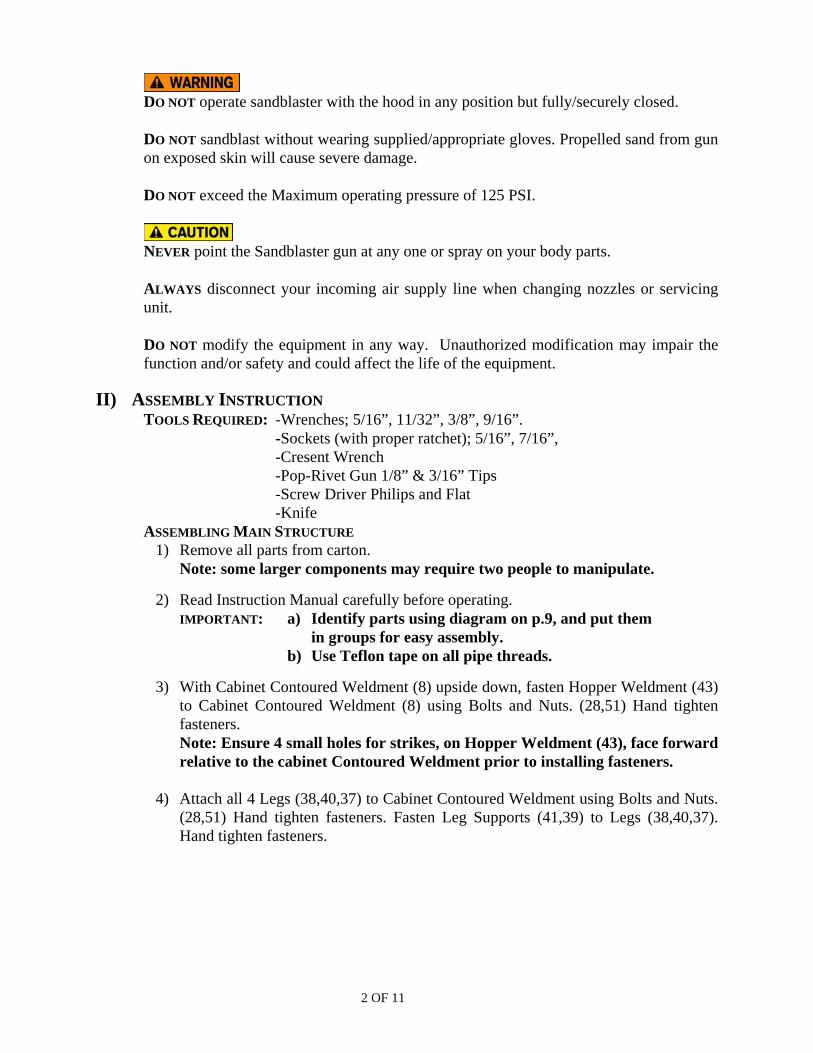
5) Attach Hinge (31) to Hopper Bottom Trap (34) using Bolts, Washers and Nuts (32,27,33). (See Orientation Note on Figure #1) Attach Strike (36) to Hopper Bottom Trap (34) using Rivets (35). (See Figure #1) Apply Foam Tape (15) to inside of Hopper Bottom Trap. Fasten remaining hinge leaf from Hopper Bottom Trap to Hopper Weldment (43) using Bolts, Washers and Nuts (32,27,33). Install Zinc Latch Hook (29) to Hopper Weldment (43) using Rivets (26).
Figure #1
15
3135
3236 33 27
MOUNT HINGE WITH BARREL AWAY FROM CABINET
34
6) Fasten Air Regulator Bracket (56) to right side of Hopper Weldment using Rivets (23).
7) Flip cabinet onto its legs on a level surface. Tighten leg fasteners. Then tighten Hopper Weldment fasteners. 8) Insert Tray (42) and Tube Suction Hopper Assy. (1) into Cabinet.
Note: Use caution when inserting the Tray as it has many sharp edges. Wearing gloves is recommended.
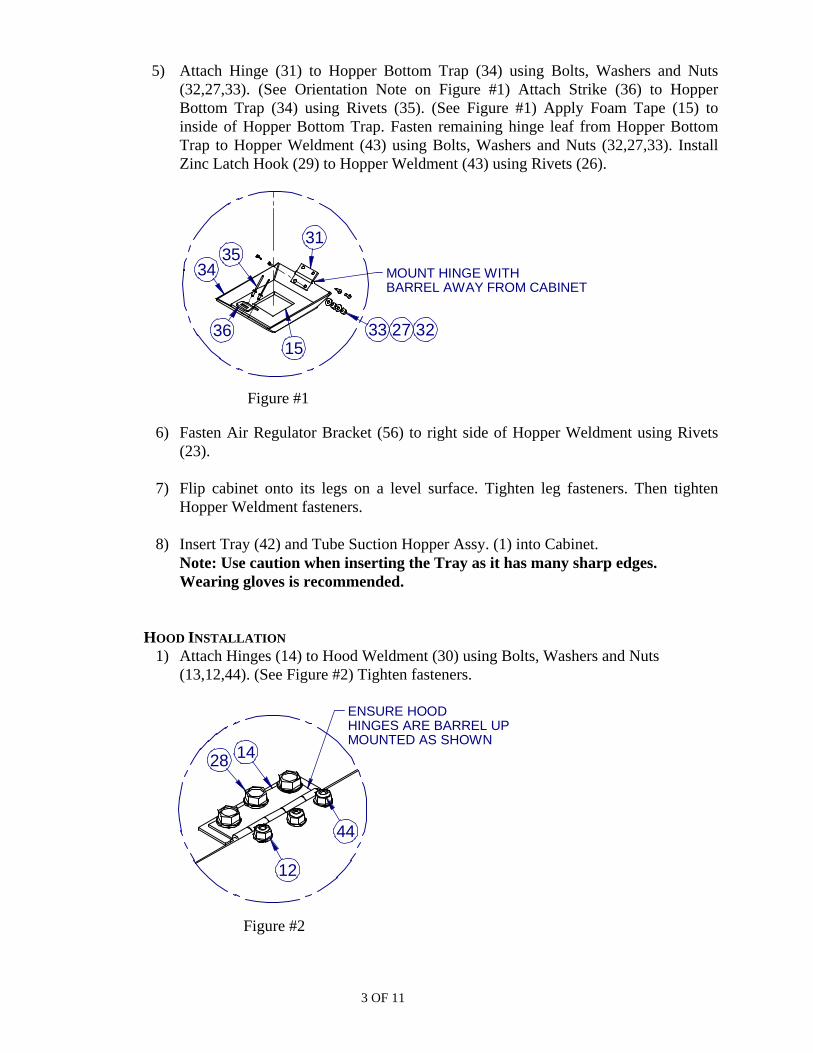
HOOD INSTALLATION 1) Attach Hinges (14) to Hood Weldment (30) using Bolts, Washers and Nuts
(13,12,44). (See Figure #2) Tighten fasteners.
ENSURE HOOD HINGES ARE BARREL UPMOUNTED AS SHOWN
28
12
44
14
Figure #2
3 OF 11

2) Apply Foam Tape (15) to Cabinet Contoured Weldment (8) to provide seal for Hood Weldment. (See Figure #4)
3) Attach Zinc Latch (29) to front of Hood Weldment (30) using Rivets (26). (See Figure #3) Attach Handle (25) using Bolts and Nuts (28,53).
Figure #3
Figure #4
2629
51
2847
15
4) Install both Lid Stays (47,48) into position in Contoured Cabinet (8) on both sides using Bolts and Nuts (28,51). (See Figure #4) Let lid stays hang within Cabinet.
5) Place Hood Weldment into position on Main Cabinet Structure. Attach 3 remaining hinge leaves from Hood Weldment to top of Cabinet Contoured (8) using Bolts and Nuts (28,51). (See Figure #3) Hand tighten fasteners.
6) Align Hood Weldment on Cabinet so that Foam Gasket (15) forms a seal all around
edges. (See Figure #4) 7) Tighten Hinge fasteners that were previously hand tightened. (from Step 5) 8) Lift Hood Weldment with one arm and extend Lid Stays (47,48) to full extension,
locking them both in the extended position. Fasten bracket, on free end of Lid Stay, onto threaded studs on inside of Hood Weldment using Nuts (51). (Note: Fully extend Lid Stays to unlock stays and lower the hood once nuts have been tightened onto the threaded studs.)
4 OF 11

ACCESSORY INSTALLATION
1) Mount Glove Moulding Assembly (24,49) into Hood Weldment using Bolts and Nuts (9,10).
2) Attach Sandblasting Gloves (21) to Glove Support Moulded (24) using Clamps
(22). Note: Assure proper orientation and alignment of glove before tightening clamps.
3) Remove protective film from both sides of Acrylic Sheet. Attach Acrylic Sheet to
Hood Weldment using Rivets (23).
4) Fasten Strikes (36) to front lip of Hopper Weldment using Bolts, Washers and Nuts (53,54,55). Note: Strikes should be installed so that they point upwards. (See Figure #5)
5) Mount Light Fixture (20) to back wall of Cabinet using Bolts and Nuts (9,10). The
Light Fixture should be oriented in such a way that the switch is at the bottom right of the fixture and that the cord protrudes through back of the cabinet through the hole provided. Note: Light fixture may have to be opened up in order to securely fasten to back of cabinet wall.
6) Apply protective Window Film (50) to INSIDE of Acrylic Sheet to protect the plastic
sheet from damage due to abraision from blasting.
PLUMBING INSTALLATION 1) Thread Hose Barb (45) into outlet of Air Regulator (52).
Note: Arrow on regulator points towards outlet.
2) Mount Air Regulator by placing AirRegulator Bracket between pressure gaugeand regulator body by unscrewing gauge,moving threaded gauge fitting through AirRegulator Bracket opening and screwinggauge back into the regulator body.
Note; Arrow on regulator indicates flow of air. Arrow must point towards outlet/hose (19) that is plumbed into 90 deg. Brass Elbow (16) outlined in step 5.
Figure #5
45
18
2352
56
3653
3) Thread Hose Barb (17) into one end of Elbow (16).
5 OF 11
6 OF 11
4) Placing Connector (46) through hole, on right side of Cabinet from inside outward
and thread on Elbow (16) as shown. Angle Hose Barb on Elbow towards Air Regulator.
5) Install 3/8” Hose (19) onto Hose Barbs between Elbow (16) and Air Regulator (52)
using Clamps (18).
6) Thread Hose Barb (6) onto Swivel Adaptor (5). Thread Swivel Adaptor (5) to Sandblasting Gun (4).
7) Thread Hose Barb (6) onto Connector (46).
8) Install 3/8” Hose (7) onto Hose Barbs (6) between Connector (46) and Swivel
Adaptor (5) using Clamps (18).
9) Install 1/2” Hose (2) onto Hose Barb on bottom of Sandblasting Gun (4) and to one tube of “Y”-shaped end of Tube Suction Hopper Assy. (1) using Clamps (3).
10) Connect air supply to inlet port on Air Regulator (52).
NOTE: To ensure proper operation, unit must be placed on flat surface. If required place shims under legs to keep unit level. Failing to do so may cause hood to close incorrectly and thus not seal properly.
III) START UP/BREAK IN
1) Remove air supply. 2) Open hood. 3) Fill Hopper with abrasive.
Important: Do Not fill above ¾ of hopper.
Note: A) All sand should be dry and uniformly graded
B) Ensure there is no sand built up on seals while filling, clean and remove all abrasive material from foam seal.
4) Prepare your part to be sandblasted and make sure the hood is closed.
Note: Make sure your compressor is on and connected to the Sandblaster.
5) Wait for the pressure in the compressor tank to build up 80 PSI or more.
Warning: Never operate your Sandblaster above 125 PSI.
6) While holding gun, pull trigger to administer sand.
Note: Before sandblasting, read all caution and warning decals.
7 OF 11
YOU ARE NOW READY TO SANDBLAST!!!
7) Operating Tips:
7.1 Abrasive: You can use any suitable, clean sand, glass or metal beads, Aluminum Oxide, walnut shells, etc.
7.2 Mask workpiece surfaces not needing sandblasting in a suitable manner.
7.3 Ensure Hood is in place when operating your Sandblaster. (Ensure proper sealing)
7.4 The effectiveness of the blaster is increased by holding the nozzle as close to
the area being cleaned as possible.
7.5 Move the blaster in steady, even strokes over the area to keep sandblasting surface even.
7.6 After blasting, clean surface with blow gun (optional kit) or brush to remove
any abrasive that may be remaining on the part.
7.7 Refinish promptly after sandblasting as newly sandblasted metal surface is more susceptible to corrosion.
IV) TO STOP SANDBLASTING 1) Remove finger from gun trigger. 2) Close ball valve on air supply for fixed gun. (for optional fixed gun kit) 3) Disconnect air supply.
V) TO EMPTY SANDBLASTER
1) Follow instruction IV. 2) Find a suitable container to collect abrasive. 3) Place a container under hopper trap. 4) Open trap.
VI) POINTS TO REMEMBER
1) If sand or abrasives become clogged in gun, disconnect air supply and unscrew nozzle on gun. Clean out as necessary.
2) Always operate with trigger fully open or fully closed. 3) Make sure you use the right abrasive and nozzle.
For Course Abrasive use 5/16 nozzle orifice. For Fine Abrasive use 1/4 nozzle orifice.
4) Replace worn nozzle as required.
NOTE: Replace nozzle after the orifice has worn to more that 1.50 times its original diameter or the pressure drops and cannot build up to 80 PSI.

8 OF 11
VII) NOZZLE REMOVAL AND INSPECTION 1) Disconnect air supply. 2) Unscrew Nozzle fastening ring and remove Nozzle from Gun. 3) Inspect Nozzle for wear and replace if worn.
VIII) SPECIFICATIONS
STANDARD FEATURES AND SPECIFICATIONS - Trigger operated Sandblast gun. - Front lid access. - Overall weight 225 lbs. - 1/4” Nozzle (12 cfm minimum) - Overall dimensions 48” x 60” x 24”. - Maximum 125 psi. - Trap door for easy abrasive removal. - Replaceable film for hood viewing glass.
OPTIONAL PARTS
- Replacement 1/4” nozzles part # 6320055 for ANI gun available at Princess Auto Store.
- Replacement 1/4” nozzles part # 6320036 for Gyson gun available at Princess Auto Store.
- Gyson 400 series gun, hanging bracket and necessary hardware. (optional kit) - 5/16” Nozzle – for Gyson gun - (16 cfm minimum) part # 6320035 available at
Princess Auto Store. - Replacement film is available for hood viewing glass.

16 17
40
3837
39
41
30
43
8 42
1
20
4
52
6
45
28
22
18
3
21
25
14
29
15
19
7
2
10
23
9
5
15
11
24
28
26
53
18
28
LIG
HT
MO
UN
TED
TO B
AC
K W
ALL
910
SANDBLASTER CABINETHEAVY DUTY
ITEM #8001312
46
4728
49
48
50FIG
UR
E #
4
FIG
UR
E #
3
3233
27
35
FIG
UR
E #
2
FIG
UR
E #
1
FIG
UR
E #
5
5151
51
4413
12
5128
5355
54
36
2356
6
A
5758
59
9 of 11

PARTS LISTSANDBLASTER CABINET HEAVY DUTY ITEM #8001312
No. Item No. Description Qty1 10001112 TUBE SUCTION HOPPER ASSY 12 HOSE .500 ID X 42" LG 13 CLAMP SCR SS .625 X 1.250 24 8001661 TRIGGER OPERATED SANDBLAST GUN 15 SWIVEL ADAPTOR .25 NPTF X .25 NPTM 16 BARB B .375 X .25 NPTF 27 HOSE .375 ID X 42" LG 18 10001107 CABINET CONT. WELDMENT 19 SCREW .125 X .75 LG 1610 NUT HEX .125 1611 VENT PLUG MESH 212 WASHER #8 913 SCREW #8-32 UNC X .50 LG 914 HINGE 3.00 X 2.00 X .06 THK 315 FOAM TAPE .75 W X .25 T X 16 FT LG 116 ELBOW B .25 NPTF 90 DEG 117 BARB B .375 X .25 NPTM 118 CLAMP SCR SS .312 TO .875 419 HOSE .375 ID X 24" LG 120 10001154 FIXTURE LIGHT 36 IN. 121 5050107 GLOVE SANDBLASTER 24" 222 CLAMP GLOVE MOUNT 223 RIVET POP .19 DIA LONG 2224 GLOVE SUPPORT MOULDED 225 HANDLE HOOD 126 RIVET POP .19 DIA MED 427 WASHER #6 428 BOLT HEX SER. .312-18UNC X .50 LG 6729 LATCH 330 10001104 HOOD CABINET WELDMENT 131 HINGE 1.50 X 1.38 X .06 THK 132 SCREW #6-32 UNC X .50 LG 433 NUT LOCK NYLON #6-32 UNC 434 10001108 HOPPER BOTTOM TRAP 135 RIVET POP .13 DIA 236 STRIKE 337 10001101 LEG FRONT RIGHT 138 10001100 LEG FRONT LEFT 139 10001102 LEG SUPPORT SIDE 240 10001099 LEG BACK 241 10001103 LEG SUPPORT ACROSS 242 10001111 TRAY 143 10001106 HOPPER STR. WALL WELD'T 144 NUT LOCK NYLON #8-32 UNC 945 BARB B .375 X .375 NPTM 146 NIPPLE HEX .25 NPTM 147 LID STAY R 148 LID STAY L 149 GASKET GLOVE SUPPORT 2
10 of 11

50 10001158 FILM WINDOW 12 IN X 36 IN X .005 IN 151 NUT HEX SER. .375-16 UNC 7152 AIR REGULATOR .375 PORT 153 SCREW #6-32 PAN HEAD 454 WASHER LOCK SPLIT REG .156 PTD 455 NUT HEX #6-32 456 BRACKET AIR REGULATOR 157 DECAL POWERFIST SANDBLAST CABINET 158 DECAL CAUTION SANDBLAST CABINET 159 DECAL PAL SERIAL # 1
11 of 11