sanatron acrylic vacuum chamber operations, maintenance ... · sanatron acrylic vacuum chamber...
TRANSCRIPT

Sanatron Acrylic Vacuum Chamber
Operations, Maintenance, and User Manual
We Carry 30 Standard Sizes Including, Square,
Cylindrical, Cubic, and Custom Acrylic Vacuum
Chamber!
Sanatron Acrylic Vacuum Chamber Operations, Maintenance, and User Manual
Document #:
443302
426 South 1000 East STE708 Salt Lake City, UT 84102
Web: www.sanatron.com Email: [email protected] Phone: (801) 876-0831
Page 2 of 31
Table of Contents 1. Introduction ..................................................................................................................................................................... 3
2. Taking Care of your Acrylic Vacuum Chamber ........................................................................................................ 4
3. How to Clean the Acrylic Vessel.................................................................................................................................. 5
4. Vacuum Chamber Specifications ................................................................................................................................. 6
A. Vacuum Rating .......................................................................................................................................................... 6
B. Physical Properties .................................................................................................................................................... 6
C. Environmental Conditions for Operations ........................................................................................................... 6
5. Acrylic Vacuum Chamber Operations ........................................................................................................................ 7
A. Receiving and Unpacking your Chamber .............................................................................................................. 7
B. Connecting your Vacuum Chamber to the Vacuum Pump ............................................................................... 8
C. Explanation of Vacuum Chamber Components ............................................................................................... 11
D. Creating Vacuum inside your Vacuum Chamber .............................................................................................. 14
E. Releasing Vacuum and Venting your Vacuum Chamber ................................................................................. 14
F. Pressurizing your Chamber .................................................................................................................................... 15
6. Conversion Tables ........................................................................................................................................................ 16
A. Pressure and Vacuum Conversion Table ........................................................................................................ 16
B. Altitude vs. Pressure Conversion Table .......................................................................................................... 17
Appendix A: Adjusting Door Hinges ............................................................................................................................ 18
Appendix B: Replacing your O-Ring ............................................................................................................................. 29
Appendix C: Replacing the Spring Support Cylinder ................................................................................................. 31

Sanatron Acrylic Vacuum Chamber Operations, Maintenance, and User Manual
Document #:
443302
426 South 1000 East STE708 Salt Lake City, UT 84102
Web: www.sanatron.com Email: [email protected] Phone: (801) 876-0831
Page 3 of 31
1. Introduction On behalf of Team Sanatron, we want to thank you for purchasing our products and letting us serve you. It is because of your support that we at Sanatron get to do what we are passionate about. Our goal is to be your partner when it comes to vacuum technology. We are happy to help you design and build the world as we see it today. We also want to inspire you to rise above and to envision, develop, and build engineering systems for a better future tomorrow which seemed almost impossible today. We stand 100% behind everything we make and deliver to you! This means that you have our service when you need it. You are welcome to contact us whenever, regardless what questions you may have
or what warranty terms and conditions say. Every chamber is specified, designed, built, and quality inspected by us specifically for you. In order to get the most out of your chamber, please take the time to fully read and understand this document. Following this Installation, Operations, and Maintenance Manual will: 1. Ensures an effective and efficient operation. 2. Prolong the life and quality of this equipment. 3. Maintain a safe and secure work environment. LEGAL NOTICE: Sanatron makes no warranties applying to information contained in this document or its suitability for any implied or inferred purpose. Sanatron shall not be held liable for any errors this manual contains or for any damages that result from its use. By using this chamber or manual, the user/operator agrees to operate this chamber voluntarily, at own discretion, and at their own risk. Operator must comply with safety instructions, observe workplace safety rules, and follow regulations issued by corresponding government agencies. WARNING: Misuse of this equipment may result in equipment damage or personal injury. DO NOT make unapproved modifications to this chamber
Sanatron Acrylic Vacuum Chamber Operations, Maintenance, and User Manual
Document #:
443302
426 South 1000 East STE708 Salt Lake City, UT 84102
Web: www.sanatron.com Email: [email protected] Phone: (801) 876-0831
Page 4 of 31
2. Taking Care of your Acrylic Vacuum Chamber WARNING: HEAVY! Consider that the smallest and lightest Sanatron Acrylic Vacuum Chamber weights 35lbs or more. Please use the proper lifting and moving equipment while relocating your Chamber. Do not try to lift this Acrylic Chamber by yourself. Use the same procedures that you would use when handling heavy equipment. Consult your on-site Safety Engineer or Material Handler if you are not sure how to move heavy and fragile equipment. WARNING: FRAGILE! Acrylic is fragile and will crack or craze if dropped or mishandled. You must set your Acrylic Vacuum Chamber slowly down onto your work area. Additionally, do not hit it with sharp objects such as knifes, hammers, or screwdrivers. Do not collide this system with other objects. You must handle the acrylic carefully in order to maintain it. ATTENTION! DO NOT use, apply, or expose SOLVENTS to Acrylic Chambers Solvents have the ability to attack the surface of acrylics and dissolve the polymer chains which are the building blocks or acrylic. Not only will solvents dissolve acrylic and acrylic epoxy glue, solvents will also diffuse into the acrylic and acrylic glue and weaken it. This includes, but is not limited to: isopropyl alcohol, acetone, paint thinners, and other solvents. Please do not use this chamber for Wood Impregnation as some Wood Resins outgas and the vapor from the wood resin will attack the acrylic and the acrylic epoxy glue and destabilize the acrylic vacuum chamber. DO NOT use this chamber to dry parts that have been cleaned with including, but not limited to: isopropyl alcohol, acetone, paint thinners, and other solvents. The solvent drying vapors will attack the acrylic and the acrylic epoxy glue and weaken the acrylic vacuum chamber.
Sanatron Acrylic Vacuum Chamber Operations, Maintenance, and User Manual
Document #:
443302
426 South 1000 East STE708 Salt Lake City, UT 84102
Web: www.sanatron.com Email: [email protected] Phone: (801) 876-0831
Page 5 of 31
3. How to Clean the Acrylic Vessel
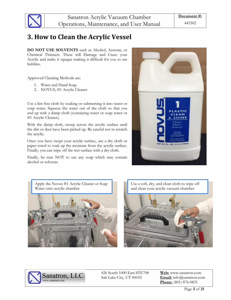
DO NOT USE SOLVENTS such as Alcohol, Acetone, or Chemical Thinners. These will Damage and Craze your Acrylic and make it opaque making it difficult for you to see bubbles.
Approved Cleaning Methods are:
1. Water and Hand Soap 2. NOVUS, #1 Acrylic Cleaner
Use a lint free cloth by soaking or submersing it into water or soap water. Squeeze the water out of the cloth so that you end up with a damp cloth (containing water or soap water or #1 Acrylic Cleaner).
With the damp cloth, sweep across the acrylic surface until the dirt or dust have been picked up. Be careful not to scratch the acrylic.
Once you have swept your acrylic surface, use a dry cloth or paper towel to soak up the moisture from the acrylic surface. Finally, you can wipe off the wet surface with a dry cloth.
Finally, be sure NOT to use any soap which may contain alcohol or solvents.
Apply the Novus #1 Acrylic Cleaner or Soap Water onto acrylic chamber
Use a soft, dry, and clean cloth to wipe off and clean your acrylic vacuum chamber
Sanatron Acrylic Vacuum Chamber Operations, Maintenance, and User Manual
Document #:
443302
426 South 1000 East STE708 Salt Lake City, UT 84102
Web: www.sanatron.com Email: [email protected] Phone: (801) 876-0831
Page 6 of 31
4. Vacuum Chamber Specifications
A. Vacuum Rating - All Acrylic Vacuum Chambers are rated to 0.075 Torr of absolute Pressure with the appropriate vacuum pump. This chamber will pull to 75 micron, -29.92 inHg, -14.69 psi, -101kPa. - The highest vacuum you can pull is dependent on two things: 1. Your altitude and the ambient pressure: You can only pull as much air as is present in the chamber. At higher altitudes, the vacuum you can pull is lower 2. Your Vacuum Pump: The vacuum level is also Dependent on the vacuum pump you have. Make sure that you have a powerful enough pump to handle this acrylic vacuum chamber. - The leak rate of this acrylic vacuum chamber is no less than 5.25 Torr (0.25 inHg) within the first 24 hours. This chamber will not lose much pressure after 24 hours and will hold the vacuum level steady for several weeks. - The internal dimensional tolerances of this chamber are +/- 0.125 inch. - Unless otherwise noted or requested in the quote, the chamber materials and the lid materials are made from Clear Cast Acrylic. - The Standard Sealing Material is a Buna-N 1/4 inch (0.275” Actual) diameter O-Ring. Viton and other types of O-Rings are available upon Request.
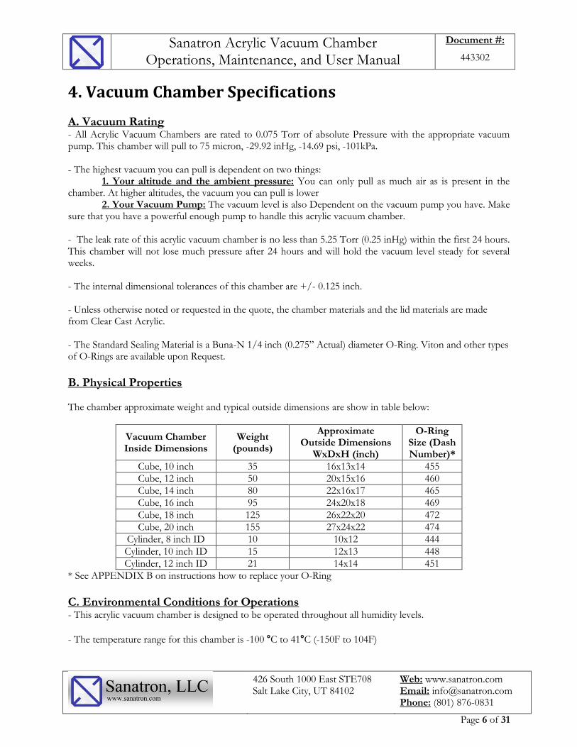
B. Physical Properties The chamber approximate weight and typical outside dimensions are show in table below:
Vacuum Chamber Inside Dimensions
Weight (pounds)
Approximate Outside Dimensions
WxDxH (inch)
O-Ring Size (Dash Number)*
Cube, 10 inch 35 16x13x14 455
Cube, 12 inch 50 20x15x16 460
Cube, 14 inch 80 22x16x17 465
Cube, 16 inch 95 24x20x18 469
Cube, 18 inch 125 26x22x20 472
Cube, 20 inch 155 27x24x22 474
Cylinder, 8 inch ID 10 10x12 444
Cylinder, 10 inch ID 15 12x13 448
Cylinder, 12 inch ID 21 14x14 451
* See APPENDIX B on instructions how to replace your O-Ring
C. Environmental Conditions for Operations - This acrylic vacuum chamber is designed to be operated throughout all humidity levels.
- The temperature range for this chamber is -100 °C to 41°C (-150F to 104F)

Sanatron Acrylic Vacuum Chamber Operations, Maintenance, and User Manual
Document #:
443302
426 South 1000 East STE708 Salt Lake City, UT 84102
Web: www.sanatron.com Email: [email protected] Phone: (801) 876-0831
Page 7 of 31
5. Acrylic Vacuum Chamber Operations
A. Receiving and Unpacking your Chamber Depending on the size, weight and complexity of your system, your vacuum chamber will arrive either in a box, crate, or pallet. Please be sure to unpack your item as soon as you can so that any damages incurred during freight can be handled quickly. During your unpacking process be sure to inspect your item for damages. If you find your item to be damaged, please contact us and depending on the shipping terms, we will either help you resolve your case or refer you to the freight company. Note that your chamber will be wrapped into packaging wrap, be extra careful removing it and if you are using a knife to cut the wrap, be sure not to cut or scratch the vacuum chamber. KEEP THE KNIFE AWAY FROM ACRYLIC. DO NOT SCRATCH ACRYLIC CHAMBER. Finally, be sure to handle your chamber with care as it is heavy. As you unpack your vacuum chamber, you may notice Styrofoam pieces, saw dust, and heavy glue smell. The Styrofoam and sawdust are easy to clean. The glue smell may be present because your chamber is built in house and made to order and is still fresh. This smell will slowly decrease and become unnoticeable after a week or two.
BE CAREFUL REMOVING THE PACKAGING WRAP. DO NOT SCRATCH ACRYLIC WITH KNIFE BLADE
MAKE SURE TO UNPACK YOUR CHAMBER ASAP

Sanatron Acrylic Vacuum Chamber Operations, Maintenance, and User Manual
Document #:
443302
426 South 1000 East STE708 Salt Lake City, UT 84102
Web: www.sanatron.com Email: [email protected] Phone: (801) 876-0831
Page 8 of 31
B. Connecting your Vacuum Chamber to the Vacuum Pump This acrylic vacuum chamber is fully setup and ready to go; all you need to do is connect the acrylic vacuum chamber to the vacuum pump. Please see the sketch below to understand how the vacuum chamber connects to the vacuum pump.
There are two most common ways to connect the vacuum pump to the vacuum chamber:
QUICK FLANGE
NPT VALVE
NPT VALVE

Sanatron Acrylic Vacuum Chamber Operations, Maintenance, and User Manual
Document #:
443302
426 South 1000 East STE708 Salt Lake City, UT 84102
Web: www.sanatron.com Email: [email protected] Phone: (801) 876-0831
Page 9 of 31
Barb Fitting: A barb Fitting is required to connect the vacuum chamber and vacuum pump. Since our standard vacuum valve is a 1/4 inch NPT, we suggest that you use a Barb that is 1/4 inch Male NPT by 3/8 Hose Diameter ID. You will also need a barb hose clamp. Repeat the same process for the vacuum pump. NOTE: Beginning October 1, 2018, all our vacuum valves will become 1/2 inch NPT. We therefore suggest that you use a BARB that is 1/2 inch NPTM by 5/8 inch ID hose diameter – this change will greatly improve the airflow and hence decrease pumpdown time of vacuum chamber.
NW Quick Flange: This is also an option that you have which is a bit better as it will decrease your pump-down times due to larger diameter hose. As an option we offer NW25 and NW40 Valve that can be connected to your chamber via a Metal Bellows Hose either NW25 or NW40. You will also need a Centering Ring and a Clamp.
REINFORCED VINYL HOSE OR VACUUM HOSE
HOSE CLAMP
HOSE BARB
METALLIC VACUUM HOSE
CENTERING RING
CLAMP

Sanatron Acrylic Vacuum Chamber Operations, Maintenance, and User Manual
Document #:
443302
426 South 1000 East STE708 Salt Lake City, UT 84102
Web: www.sanatron.com Email: [email protected] Phone: (801) 876-0831
Page 10 of 31
Once you have connected your vacuum chamber with vacuum pump properly, it should look like the image below. Please see the images below as a reference to confirm that you have connected your vacuum chamber to vacuum pump:
NPT VALVE QUICK FLANGE
Sanatron Acrylic Vacuum Chamber Operations, Maintenance, and User Manual
Document #:
443302
426 South 1000 East STE708 Salt Lake City, UT 84102
Web: www.sanatron.com Email: [email protected] Phone: (801) 876-0831
Page 11 of 31
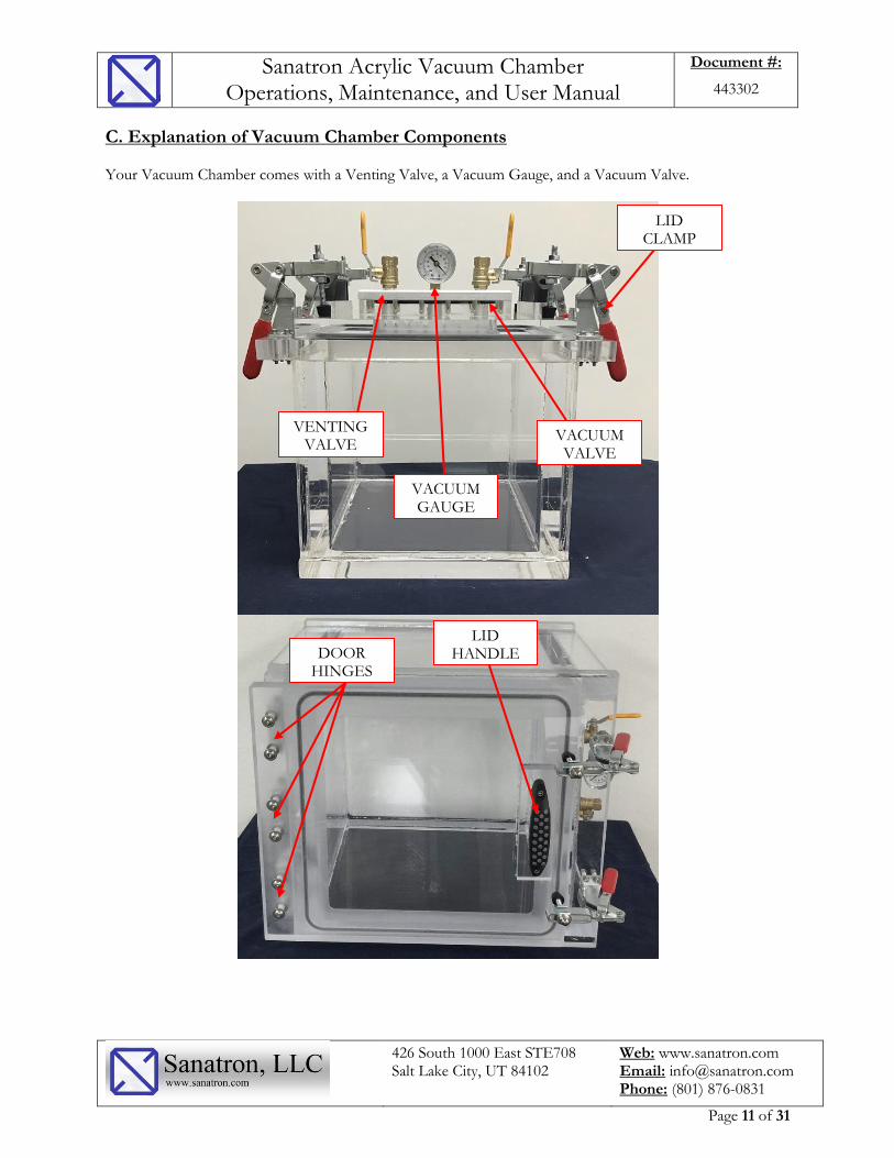
C. Explanation of Vacuum Chamber Components Your Vacuum Chamber comes with a Venting Valve, a Vacuum Gauge, and a Vacuum Valve.
VENTING VALVE
VACUUM GAUGE
VACUUM VALVE
LID CLAMP
LID HANDLE DOOR
HINGES

Sanatron Acrylic Vacuum Chamber Operations, Maintenance, and User Manual
Document #:
443302
426 South 1000 East STE708 Salt Lake City, UT 84102
Web: www.sanatron.com Email: [email protected] Phone: (801) 876-0831
Page 12 of 31
Lid Clamp is a toggle style clamp that is used to press the Lid and compress the O-Ring against the sealing surface. Most of the time, this clamp is use to initiate the vacuum at first. Once you have reached a -1psi vacuum, the vacuum force will create sufficient force to hold the O-Ring Sufficiently Compressed against the sealing surface. The Top Load, Removable Lid Model has 4 clamps, the Hinged Side Door, Front Loading Model has 2, and the Spring Supported Lid has also 2 Clamps. The Lid Handle is used to properly hold and move the vacuum chamber lid. Grab the lid Handles firmly to lift the lid from the top of the vacuum chamber. Conversely, grip the handle to open the front load and spring supported chamber. Door Hinges are present to hold the door in place and to enable you to swing the door open. Your vacuum chamber hinges will not need adjustment during the lifetime of the vacuum chamber. However, the good news is that our door hinges are the only ones on the market that are adjustable. Please see Appendix A for instructions on how to adjust the Door Hinges. The Venting Valve is not connected to anything, it is simply there to vent your chamber once you are ready to release your vacuum. You may connect a muffler or a filter onto it so that you can prevent impurities rushing into your chamber as you are releasing your vacuum. In some instances, your venting valve can be used to control the vacuum levels inside your chamber. The way to do this is to not fully open the venting valve and watch the vacuum gauge reach your desired vacuum level. Once your desired vacuum level has been reached, watch the dial, if it moves toward higher vacuum, open your venting valve a bit more. If on the other hand, you are unable to reach your desired vacuum level, close the vacuum valve a bit more. You will have to play with it a little bit but once you have dialed in your vacuum valve position, you will not need to adjust your vacuum anymore. A better way to do this vacuum control is to get a vacuum controller or a vacuum control valve installed on your system. The Vacuum Gauge shows the vacuum level inside of your chamber. Your Dial Vacuum gauge comes with a 2% to 3% accuracy and is not calibrated. If you need your vacuum gauge calibrated or if you need your vacuum gauge to be quick release as shown in image below, please contact us and we will add this to your system as an option. If you require a higher resolution vacuum display; we recommend that you install a Instrutech Stinger Gauge. This vacuum gauge is electrically powered and will display a vacuum output in Torr with 3 significant figures of accuracy. Once your vacuum level goes below 1 Torr, the vacuum display will switch to micro Torr (micron) output. This is a recommended option if you require a more accurate vacuum measurement.

Sanatron Acrylic Vacuum Chamber Operations, Maintenance, and User Manual
Document #:
443302
426 South 1000 East STE708 Salt Lake City, UT 84102
Web: www.sanatron.com Email: [email protected] Phone: (801) 876-0831
Page 13 of 31
Vacuum Gauge Options
Shown are two options. First is the quick release option that will allow for easy and periodic vacuum gauge calibration. The Second Option is the Instrutech Vacuum Gauge option which allows you to display your vacuum inside the acrylic vacuum chamber in Torr and with an accuracy of 3 significant figures.
The Vacuum Valve, which is connected to the Vacuum Pump is used to let the air be evacuated from the chamber.

Sanatron Acrylic Vacuum Chamber Operations, Maintenance, and User Manual
Document #:
443302
426 South 1000 East STE708 Salt Lake City, UT 84102
Web: www.sanatron.com Email: [email protected] Phone: (801) 876-0831
Page 14 of 31
D. Creating Vacuum inside your Vacuum Chamber To create a Vacuum, simply:
1. Close the lid 2. Close clamps so that slight pressure is applied to the Lid and O-Ring. 3. Close the Venting Valve (the valve not connected to anything) 4. Turn ON the Vacuum Pump. 5. Open the Vacuum Valve (the valve that is connects the Vacuum Pump to your Vacuum Chamber) 6. Watch the vacuum gauge display and notice your vacuum increasing. Once you have reached your
desired vacuum level, close the vacuum valve and hold your vacuum as long as you need to. Our vacuum chambers are designed to hold vacuum for an extended period of time.
E. Releasing Vacuum and Venting your Vacuum Chamber Once you are done with operating your vacuum chamber, all you have to do is:
1. Open the Venting Valve and let the vacuum release (you will hear air rushing into your chamber). 2. Turn OFF the Vacuum Pump 3. Close the Vacuum Valve (the valve that is connects the Vacuum Pump to your Vacuum Chamber) 4. Keep the Venting Valve Open and Open or Remove the Lid.
Congratulations, you have successfully operated your acrylic vacuum chamber!

Sanatron Acrylic Vacuum Chamber Operations, Maintenance, and User Manual
Document #:
443302
426 South 1000 East STE708 Salt Lake City, UT 84102
Web: www.sanatron.com Email: [email protected] Phone: (801) 876-0831
Page 15 of 31
F. Pressurizing your Chamber Your acrylic vacuum chamber can be pressurized, if you have purchased the OVERPRESSURE OPTION. The pressurization process is simple, simply connect your valve to compressed air source, but instead of vacuum, use compressed air instead. The slight over-pressurization is usually 5psig, 10psig, or 15psig. This overpressure option enables for a broader and deeper application. Each over pressurization option comes with a vacuum rated pressure relief valve that will pop open at about 15% over the rated pressure in order to vent any additional chamber pressure and keep the system safe.
THUMB SCREWS AND CLEVIS TO CLAMP THE VACUUM CHAMBER
DOOR DURING PRESSURIZATION
SWING CLAMP OUT OF WAY TO OPEN LID
SWING CLAMP IN AND HAND TIGHTEN THE SREW TO APPLY PRESSURE TO LID

Sanatron Acrylic Vacuum Chamber Operations, Maintenance, and User Manual
Document #:
443302
426 South 1000 East STE708 Salt Lake City, UT 84102
Web: www.sanatron.com Email: [email protected] Phone: (801) 876-0831
Page 16 of 31
6. Conversion Tables
A. Pressure and Vacuum Conversion Table
Gauge Vacuum
(PSI)
Absolute Pressure
(PSI) Vacuum (In. Hg)
Vacuum (mbar)
Vacuum (kPa)
Absolute Pressure (Torr)
Gauge Vacuum (mm Hg)
Percent Vacuum
(%) 0 14.70 0 0.0 0.0 760 0 0
0.49 14.24 1 33.9 3.4 735 25 3 0.98 13.75 2 67.7 6.8 709 51 7 1.47 13.26 3 101.6 10.2 684 76 10 1.96 12.76 4 135.4 13.5 658 102 13 2.45 12.27 5 169.3 16.9 633 127 17 2.95 11.78 6 203.2 20.3 608 152 20 3.44 11.29 7 237.0 23.7 582 178 23 3.93 10.80 8 270.9 27.1 557 203 26 4.42 10.31 9 304.7 30.5 531 229 30 4.91 9.82 10 338.6 33.9 506 254 33 5.4 9.33 11 372.5 37.2 481 279 36 5.89 8.84 12 406.3 40.6 455 305 40 6.38 8.35 13 440.2 44.0 430 330 43 6.87 7.86 14 474.0 47.4 404 356 46 7.36 7.36 15 507.9 50.8 379 381 50 7.86 6.87 16 541.8 54.2 354 406 53 8.35 6.38 17 575.6 57.6 328 432 56 8.84 5.89 18 609.5 60.9 303 457 59 9.33 5.40 19 643.3 64.3 277 483 63 9.82 4.91 20 677.2 67.7 252 508 66 10.31 4.42 21 711.1 71.1 227 533 69 10.8 3.93 22 744.9 74.5 201 559 73 11.29 3.44 23 778.8 77.9 176 584 76 11.78 2.95 24 812.6 81.3 150 610 79 12.27 2.45 25 846.5 84.7 125 635 83 12.76 1.96 26 880.4 88.0 100 660 86 13.26 1.47 27 914.2 91.4 74 686 89 13.75 0.98 28 948.1 94.8 49 711 92 14.24 0.49 29 981.9 98.2 23 737 96
14.7 0.00 29.92 1013.0 101.3 0 760 100
Sanatron Acrylic Vacuum Chamber Operations, Maintenance, and User Manual
Document #:
443302
426 South 1000 East STE708 Salt Lake City, UT 84102
Web: www.sanatron.com Email: [email protected] Phone: (801) 876-0831
Page 17 of 31
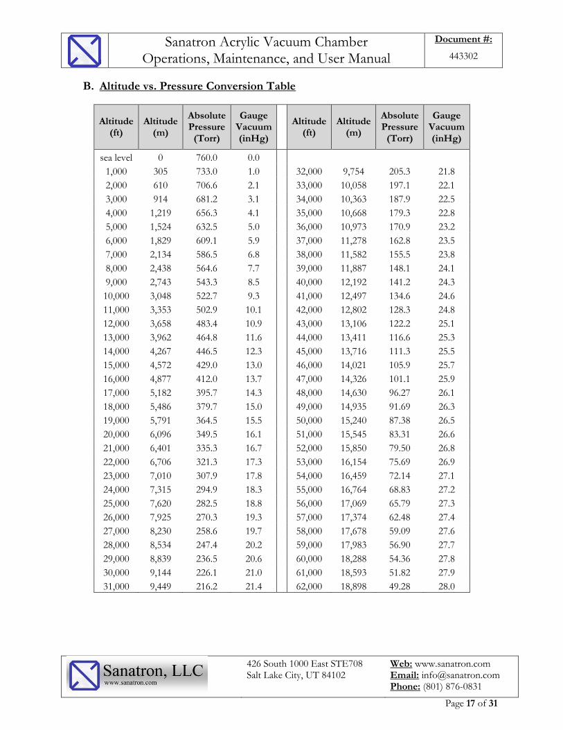
B. Altitude vs. Pressure Conversion Table
Altitude (ft)
Altitude (m)
Absolute Pressure
(Torr)
Gauge Vacuum (inHg)
Altitude (ft)
Altitude (m)
Absolute Pressure
(Torr)
Gauge Vacuum (inHg)
sea level 0 760.0 0.0 1,000 305 733.0 1.0
32,000 9,754 205.3 21.8
2,000 610 706.6 2.1
33,000 10,058 197.1 22.1
3,000 914 681.2 3.1
34,000 10,363 187.9 22.5
4,000 1,219 656.3 4.1
35,000 10,668 179.3 22.8
5,000 1,524 632.5 5.0
36,000 10,973 170.9 23.2
6,000 1,829 609.1 5.9
37,000 11,278 162.8 23.5
7,000 2,134 586.5 6.8
38,000 11,582 155.5 23.8
8,000 2,438 564.6 7.7
39,000 11,887 148.1 24.1
9,000 2,743 543.3 8.5
40,000 12,192 141.2 24.3
10,000 3,048 522.7 9.3
41,000 12,497 134.6 24.6
11,000 3,353 502.9 10.1
42,000 12,802 128.3 24.8
12,000 3,658 483.4 10.9
43,000 13,106 122.2 25.1
13,000 3,962 464.8 11.6
44,000 13,411 116.6 25.3
14,000 4,267 446.5 12.3
45,000 13,716 111.3 25.5
15,000 4,572 429.0 13.0
46,000 14,021 105.9 25.7
16,000 4,877 412.0 13.7
47,000 14,326 101.1 25.9
17,000 5,182 395.7 14.3
48,000 14,630 96.27 26.1
18,000 5,486 379.7 15.0
49,000 14,935 91.69 26.3
19,000 5,791 364.5 15.5
50,000 15,240 87.38 26.5
20,000 6,096 349.5 16.1
51,000 15,545 83.31 26.6
21,000 6,401 335.3 16.7
52,000 15,850 79.50 26.8
22,000 6,706 321.3 17.3
53,000 16,154 75.69 26.9
23,000 7,010 307.9 17.8
54,000 16,459 72.14 27.1
24,000 7,315 294.9 18.3
55,000 16,764 68.83 27.2
25,000 7,620 282.5 18.8
56,000 17,069 65.79 27.3
26,000 7,925 270.3 19.3
57,000 17,374 62.48 27.4
27,000 8,230 258.6 19.7
58,000 17,678 59.09 27.6
28,000 8,534 247.4 20.2
59,000 17,983 56.90 27.7
29,000 8,839 236.5 20.6
60,000 18,288 54.36 27.8
30,000 9,144 226.1 21.0
61,000 18,593 51.82 27.9
31,000 9,449 216.2 21.4
62,000 18,898 49.28 28.0
Sanatron Acrylic Vacuum Chamber Operations, Maintenance, and User Manual
Document #:
443302
426 South 1000 East STE708 Salt Lake City, UT 84102
Web: www.sanatron.com Email: [email protected] Phone: (801) 876-0831
Page 18 of 31
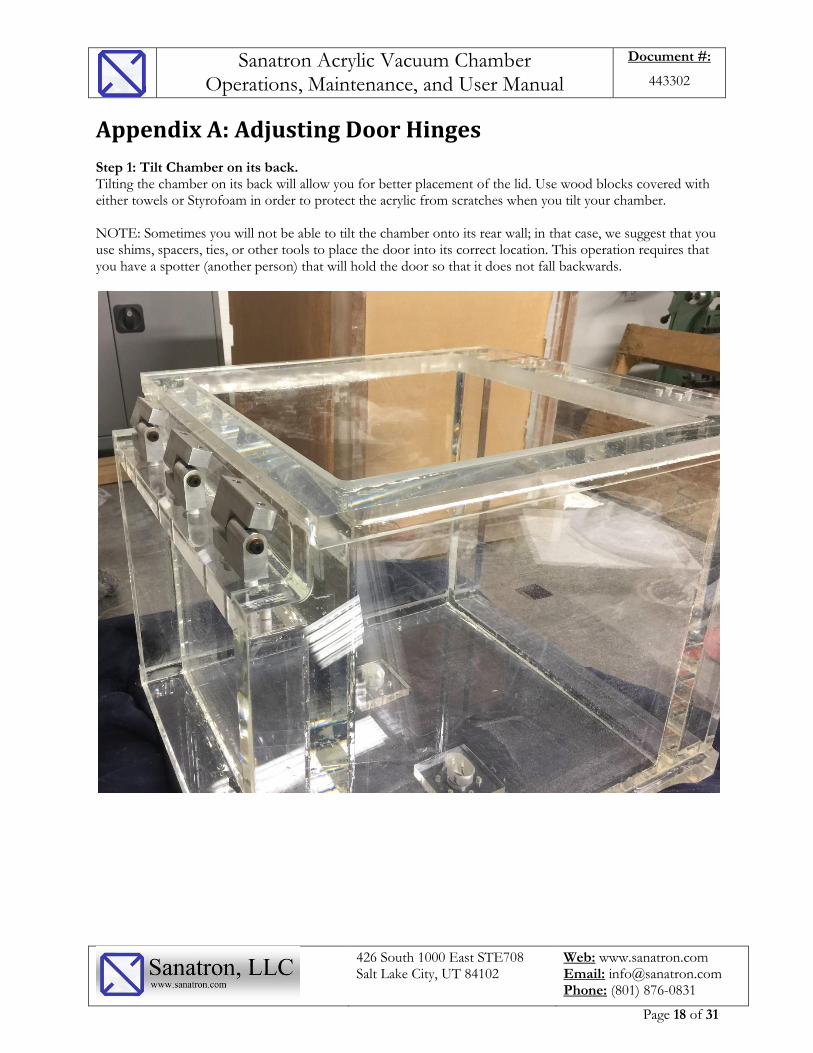
Appendix A: Adjusting Door Hinges Step 1: Tilt Chamber on its back. Tilting the chamber on its back will allow you for better placement of the lid. Use wood blocks covered with either towels or Styrofoam in order to protect the acrylic from scratches when you tilt your chamber. NOTE: Sometimes you will not be able to tilt the chamber onto its rear wall; in that case, we suggest that you use shims, spacers, ties, or other tools to place the door into its correct location. This operation requires that you have a spotter (another person) that will hold the door so that it does not fall backwards.

Sanatron Acrylic Vacuum Chamber Operations, Maintenance, and User Manual
Document #:
443302
426 South 1000 East STE708 Salt Lake City, UT 84102
Web: www.sanatron.com Email: [email protected] Phone: (801) 876-0831
Page 19 of 31
Step 2: Place the lid into its position Manually place the lid onto its position. Check to make sure that all holes align properly.

Sanatron Acrylic Vacuum Chamber Operations, Maintenance, and User Manual
Document #:
443302
426 South 1000 East STE708 Salt Lake City, UT 84102
Web: www.sanatron.com Email: [email protected] Phone: (801) 876-0831
Page 20 of 31
Step 3: Fasten each of the Hinge Bolts Fasten each of the Hinge Bolts. Do NOT tighten anything yet. Be sure to include the two nuts which you will later use to constrain the lid.

Sanatron Acrylic Vacuum Chamber Operations, Maintenance, and User Manual
Document #:
443302
426 South 1000 East STE708 Salt Lake City, UT 84102
Web: www.sanatron.com Email: [email protected] Phone: (801) 876-0831
Page 21 of 31
Step 4: Adjust the Hinge Bolts Once you have fully fastened the hinge bolts, you will notice that the lid will lift on the other side close to the clamps. Be sure not to lift the lid more than 0.125 inch. The less the lid lifts, the more flat the door is placed.

Sanatron Acrylic Vacuum Chamber Operations, Maintenance, and User Manual
Document #:
443302
426 South 1000 East STE708 Salt Lake City, UT 84102
Web: www.sanatron.com Email: [email protected] Phone: (801) 876-0831
Page 22 of 31

Sanatron Acrylic Vacuum Chamber Operations, Maintenance, and User Manual
Document #:
443302
426 South 1000 East STE708 Salt Lake City, UT 84102
Web: www.sanatron.com Email: [email protected] Phone: (801) 876-0831
Page 23 of 31
Step 5: Clamp down the Toggle Clamps
Clamp The Toggle Clamps on the other side of the lid and finalize by carefully fastening the Hinge Bolts.
You know that you have properly fastened the hinge bolts when all of the O-Ring is compressed.
Sanatron Acrylic Vacuum Chamber Operations, Maintenance, and User Manual
Document #:
443302
426 South 1000 East STE708 Salt Lake City, UT 84102
Web: www.sanatron.com Email: [email protected] Phone: (801) 876-0831
Page 24 of 31
Sanatron Acrylic Vacuum Chamber Operations, Maintenance, and User Manual
Document #:
443302
426 South 1000 East STE708 Salt Lake City, UT 84102
Web: www.sanatron.com Email: [email protected] Phone: (801) 876-0831
Page 25 of 31
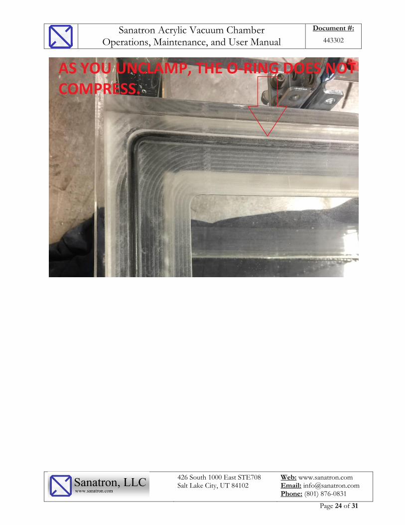
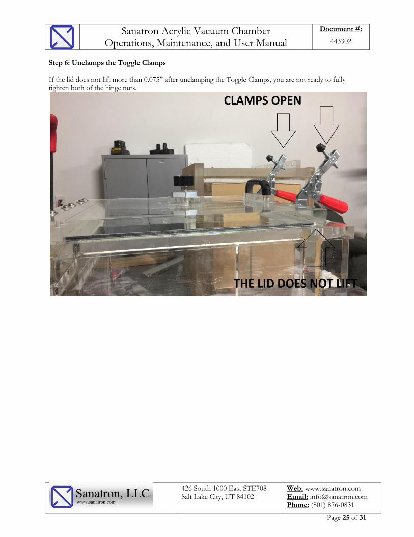
Step 6: Unclamps the Toggle Clamps If the lid does not lift more than 0.075” after unclamping the Toggle Clamps, you are not ready to fully tighten both of the hinge nuts.

Sanatron Acrylic Vacuum Chamber Operations, Maintenance, and User Manual
Document #:
443302
426 South 1000 East STE708 Salt Lake City, UT 84102
Web: www.sanatron.com Email: [email protected] Phone: (801) 876-0831
Page 26 of 31
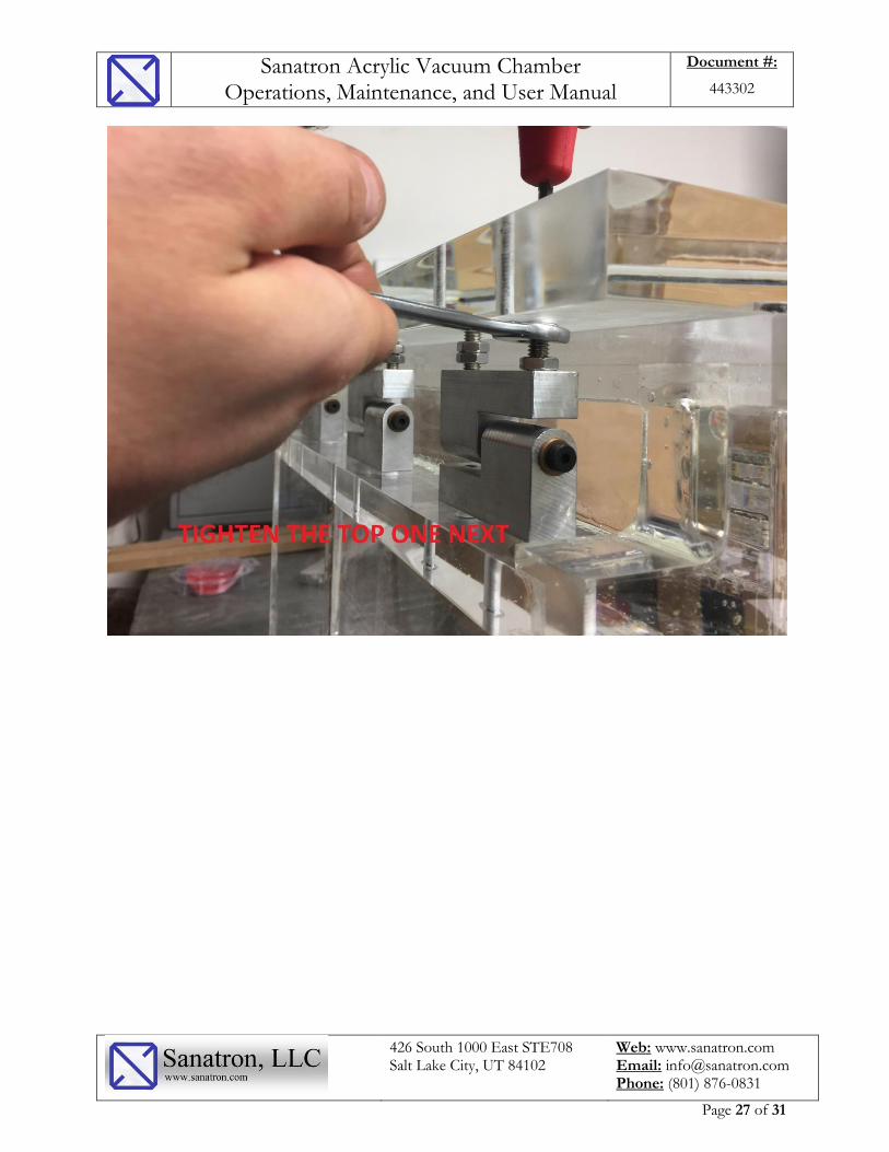
Step 7: Fasten the Hinge Nuts.
Hold the Hinge Bolt stationary with an Allen Wrench to prevent it from turning. Tighten the bottom Hinge Nut first, then move onto the top hinge nut.
Sanatron Acrylic Vacuum Chamber Operations, Maintenance, and User Manual
Document #:
443302
426 South 1000 East STE708 Salt Lake City, UT 84102
Web: www.sanatron.com Email: [email protected] Phone: (801) 876-0831
Page 27 of 31

Sanatron Acrylic Vacuum Chamber Operations, Maintenance, and User Manual
Document #:
443302
426 South 1000 East STE708 Salt Lake City, UT 84102
Web: www.sanatron.com Email: [email protected] Phone: (801) 876-0831
Page 28 of 31
Step: 8: test the Door Opening Mechanism while the chamber is laying on its back Unclamp the toggle Clamps and open the Door. Make sure that the door does not wiggle but that it is fully fastened. Close the door and make sure that you are able to close it properly. Also make sure that the O-Ring is slightly compressed when you are clamping your Toggle Clamps. Step 9: Tilt the chamber back to its original position. NOTE: You do not have to do this Step if you have not tilted the chamber onto its rear. Step 10: Vacuum Test Your Chamber Connect your chamber to a vacuum pump, pull a vacuum and test for pumpdown times. Listen and check for leaks. A this point, you should be good.
Sanatron Acrylic Vacuum Chamber Operations, Maintenance, and User Manual
Document #:
443302
426 South 1000 East STE708 Salt Lake City, UT 84102
Web: www.sanatron.com Email: [email protected] Phone: (801) 876-0831
Page 29 of 31
Appendix B: Replacing your O-Ring The lifetime of your O-Ring depends on how often the vacuum chamber is used. Generally Speaking it should last you for many years. Fortunately, O-Rings are off-the-shelf and can be purchased from your local O-Ring supplier, online, or from Sanatron. The suggested O-Ring Material is either Buna-N or Viton. See Table for O-Ring Sizing of your vacuum chambers below:
Vacuum Chamber Inside Dimensions
O-Ring Size (Dash Number)*
Cube, 10 inch 455
Cube, 12 inch 460
Cube, 14 inch 465
Cube, 16 inch 469
Cube, 18 inch 472
Cube, 20 inch 474
Cylinder, 8 inch ID 444
Cylinder, 10 inch ID 448
Cylinder, 12 inch ID 451
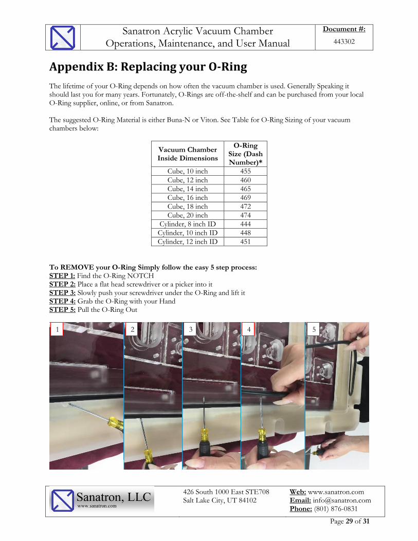
To REMOVE your O-Ring Simply follow the easy 5 step process: STEP 1: Find the O-Ring NOTCH STEP 2: Place a flat head screwdriver or a picker into it STEP 3: Slowly push your screwdriver under the O-Ring and lift it STEP 4: Grab the O-Ring with your Hand STEP 5: Pull the O-Ring Out
1 2 3 4 5

Sanatron Acrylic Vacuum Chamber Operations, Maintenance, and User Manual
Document #:
443302
426 South 1000 East STE708 Salt Lake City, UT 84102
Web: www.sanatron.com Email: [email protected] Phone: (801) 876-0831
Page 30 of 31
To INSTALL your O-Ring Simply Press the O-Ring into the O-Ring Groove. You start at one point and slowly work your way around the O-Ring Groove. You may have to stretch your O-Ring a little - that is OK. As you work your way around the O-Ring Groove, be sure to check to make sure that the O-Ring is fully inserted into the O-Ring Groove. In the end, run your fingers across the whole O-Ring and confirm that there are no bumps present. If bumps are present, simply push them in. Congrats, your O-Ring is now fully installed!

Sanatron Acrylic Vacuum Chamber Operations, Maintenance, and User Manual
Document #:
443302
426 South 1000 East STE708 Salt Lake City, UT 84102
Web: www.sanatron.com Email: [email protected] Phone: (801) 876-0831
Page 31 of 31
Appendix C: Replacing the Spring Support Cylinder There are some instances where you will have to replace the spring support cylinder on your vacuum chamber. Fortunately, this process is fairly straight forward. Please Follow the simple 7 Steps below to release the gas spring out of the Ball Socket STEP 1: Locate the Ball Socket at both ends of the Spring Support Cylinder STEP 2: Take a small flat head screw driver and dig it under the Retaining Clip STEP 3: Use the screwdriver head to pull the retaining clip back STEP 4: As the Retaining clip is pulled back, pull on the ball socket to disconnect it from the ball stud STEP 5: Push the retaining clip into place. Unscrew the ball socket from the old cylinder and screw it onto the new cylinder STEP 6: Repeat steps 1 to 5 for the other ball socket STEP 7: Pop the new cylinder with the screwed on ball sockets into the ball stud
1 2 3 4 5
Ball Sockets