samples canbus data directly - campbell sci · pdf filecmpnents sdm-can datalogger-to-canbus...
TRANSCRIPT
COMPONENTS
SDM-CANDatalogger-to-CANbus Interface
Samples CANbus Data DirectlyUses latest CAN controller
www.campbellsci.com/sdm-can
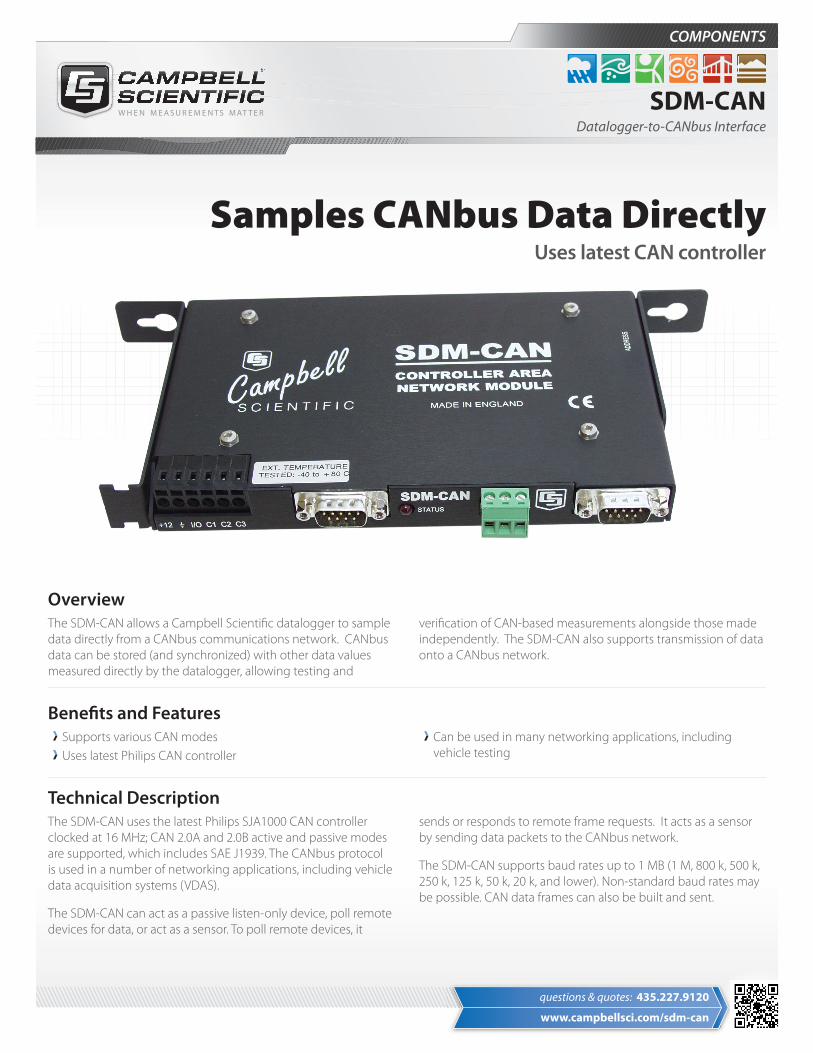
OverviewThe SDM-CAN allows a Campbell Scientific datalogger to sample data directly from a CANbus communications network. CANbus data can be stored (and synchronized) with other data values measured directly by the datalogger, allowing testing and
verification of CAN-based measurements alongside those made independently. The SDM-CAN also supports transmission of data onto a CANbus network.
Benefits and FeaturesSupports various CAN modesUses latest Philips CAN controller
Can be used in many networking applications, including vehicle testing
Technical DescriptionThe SDM-CAN uses the latest Philips SJA1000 CAN controller clocked at 16 MHz; CAN 2.0A and 2.0B active and passive modes are supported, which includes SAE J1939. The CANbus protocol is used in a number of networking applications, including vehicle data acquisition systems (VDAS).
The SDM-CAN can act as a passive listen-only device, poll remote devices for data, or act as a sensor. To poll remote devices, it
sends or responds to remote frame requests. It acts as a sensor by sending data packets to the CANbus network.
The SDM-CAN supports baud rates up to 1 MB (1 M, 800 k, 500 k, 250 k, 125 k, 50 k, 20 k, and lower). Non-standard baud rates may be possible. CAN data frames can also be built and sent.
questions & quotes: 435.227.9120
© 1999, 2018Campbell Scientific, Inc.
January 8, 2018
Campbell Scientific, Inc. | 815 W 1800 N | Logan, UT 84321-1784 | (435) 227-9120 | www.campbellsci.comUSA | AUSTRALIA | BRAZIL | CANADA | CHINA | COSTA RICA | FRANCE | GERMANY | SE ASIA | SOUTH AFRICA | SPAIN | UK
SDM Operation
aThe device can be vertically mounted with all the connectors on the top surface
The datalogger enables individual modules through an address-ing scheme; up to 15 SDM-CANs can be connected to one data-logger. After a module is enabled, it operates independently of
the datalogger until additional commands are received or results are transmitted.
SDM-CAN HelperSDM-CAN Helper is an add-on program for our RTDAQ Real-Time Data Acquisition Software. This add-on program walks users through the process of configuring their SDM-CAN, connecting the SDM-CAN to the datalogger, sending an appropriate pro-gram to the datalogger, and setting up their datalogger to collect specific values from the CANbus network.
SDM-CAN Helper is available, at no charge, from:
www.campbellsci.com/downloads
Users must have a valid installation of RTDAQ on their computer to install the SDM-CAN Helper program.
Ordering InformationSynchronous Device for Measurement
SDM-CAN Datalogger to CANbus Interface
Mounting Kit
13958 SDM-CAN Mounting Kit for CR9000(X) Slot. An SDM-CAN, fitted with the 13958, occupies one slot in the CR9000(X) chassis. Please note that the mounting bracket that comes attached to the SDM-CAN must be removed prior to mounting the SDM-CAN to the 13958’s metal brackets.
SDM-to-Datalogger Cable
CABLE5CBL-L 5-conductor, 24 AWG cable with drain wire and Santoprene jacket. Enter cable length, in feet, after the -L. Must choose a cable termination option (see below).
Cable Termination Options (choose one)
-PT Cable terminates in stripped and tinned leads for direct connection to a datalogger’s terminals.
-PW Cable terminates in connector for attachment to a prewired enclosure.
SpecificationsOperating Voltage Range: 7 to 26 VdcOptional (switch selectable) galvanic isolation between the datalogger and the CANbus. The minimum isolation break-down is 50 V; this barrier is for signal isolation only (i.e., it is not a safety barrier)Uses the latest Philips SJA1000 CAN controller clocked at 16 MHzCANbus physical connection conforms to CIA draft standard 102 version 2, 9-pin D connector. (The interface will differ from this standard only with respect to pin 9, which outputs 5 Vdc instead of 7 to 13 Vdc)EU Declaration of Conformity document available at: www.campbellsci.com/sdm-canA three-way, unpluggable screw terminal block for CAN High, Low, and G providedFor safety reasons, can disable CANbus transmit and acknowl-edge via a jumper (e.g. for in-vehicle, listen only monitoring)
Maximum Cable Length: 6 m (20 ft) total to all SDM devices. Consult Campbell Scientific if longer lengths are necessaryDimensionsa: 17.5 x 10.0 x 2.3 cm (6.9 x 3.9 x 0.9 in)Weight: 0.3 kg (0.14 lb)
Typical Current ConsumptionActive in Self-Powered, Isolated Mode: 70 mA (recessive state); 120 mA (dominant state)Active, Non-Isolated: 30 mA (recessive state); 70 mA (dominant state)Standby (with or without isolation): < 1 mACommunications with Datalogger: 50 mARS-232 Port Active: 50 mA