canbus - mts sensors
TRANSCRIPT

T E M P O S O N I C S ® R S E R I E S
550541 G
• High-speed 2-wire digital data transmission
• Industrial standard communications protocol
• Up to 2 micron resolution
• Multiple (magnet) position sensing
• Programmable limit switch outputs
• Sensor-based intelligence & diagnostics
• Modular, non-contacting design
• Field replaceable sensor cartridge (Model RH only)
• CE Certified
• 2-year Warranty
mAll specifications are subject to change. Please contact MTS for specifications critical to your needs.* For all sensor models except the RP with style M magnet** Does not include mechanical backlash on RP model sensors, style V and S magnetsRefer to Installation Guide, Part No. 550573 for additional information, (www.mtssensors.com).
CANBUSP A R A M E T E R S P E C I F I C A T I O N
Measured Variable: Displacement, VelocityResolution: Up to 0.002 mm (0.00008 in.)Non-Linearity: < ± 0.01% of full stroke or ± 0.04 mm (0.0016 in.),
whichever is greater*
Repeatability: < ± 0.001% of full scale or ± 0.0025 mm (0.0001 in.),whichever is greater
Hysteresis (Magnetic**): < 0.004 mm (0.00016 in.)Output signal: CAN Fieldbus System ISO-DIS 11898Data Protocol: CANopen Encoder Profile DS-406, CIA Standard DS-301
V3.0 or CANbasic CAN 2.0 ABaud Rate: 1 Mbit/sec. maximumMeasuring Range: Profile Style Sensors (RP): 25 to 5000 mm (1 to 196 in.)
Rod Style Sensors (RH): 25 to 7600 mm (1 to 300 in.)Operating Voltage: +24 Vdc (+ 20%, - 15%)Power Consumption: 100 mA (typical)Operating Temperature: Head Electronics: - 40 to 75°C (- 40 to 167°F)
Sensing Element: - 40 to 105°C (- 40 to 221°F)EMC Test: DIN IEC 801-4, Type 4, CE Qualified
DIN EN 50081-1 (Emissions), DIN EN 50082-2 (Immunity)Shock Rating: 100 g (single hit)/IEC standard 68-2-27 survivabilityVibration Rating: 5 g/10-150 Hz/IEC standard 68-2-6
PROFILE STYLE (RP MODEL)Electronic Head: Aluminum die-cast housingSensor Stroke: Aluminum profileSealing: IP 65Mounting: Adjustable mounting feet or T-slot M5 nut in
base channelMagnet Type: Captive sliding magnet or floating magnet
ROD STYLE (RH MODEL)Electronic Head: Aluminum die-cast housingSealing: IP 67Sensor Rod: 304L Stainless steelOperating Pressure: 350 bar static, 690 bar spike
(5000 psi static; 10,000 psi spike)Mounting: Threaded flange M18 x 1.5 or 3/4-16 UNF-3ATypical Mounting Torque:
45 N-m (33 ft. - lbs.)Magnet Type: Ring or floating magnet
+ 0.2
+ 0.1
0
- 0.1
- 0.2
mm
0 250 500 750 1000 1250 1500 1750 2000 2250 2500mm
Example: Sensor Type: Temposonics RPMeasuring Range: 2500 mmNon-linearity (measured): ± 0.116 mm
P r o d u c t S p e c i f i c a t i o n s
Temposonics RHwith Standard Ring Magnet
Temposonics RPwith Floating Magnet
Temposonics RPwith Captive Sliding Magnet
F e a t u r e s
27295 8/11/03 7:42 AM Page 1

2
C A N B U S O U T P U T
T E M P O S O N I C S R S E R I E S S E N S O R S W I T H C A N B U S C O M M U N I C AT I O N S
•Sensor-based intelligence,
built-in diagnostics
•Reliable high speed data
transmission over 2-wire
bus
•High baud rate
(up to 1 Mbit/second)
•Up to 32 devices per bus
system
•Mode Selection
•Priority adjustability
• Easy expandability
B E N E F I T S
Posi
tion
Info
rmat
ion
CAN
Con
trolle
r
Memory
Mic
ropr
oces
sor
Sensor Block DiagramTemposonics R Series “smart” position
sensors with CANbus, (Controller Area
Network), fieldbus expand the function-
ality of our top of the line displacement
sensing models. This enables customers
to apply highly reliable, accurate and
responsive position sensing to a simple,
low cost fieldbus network. CANbus is a
bus architecture that includes high-speed
data processing suitable for motion con-
trol in industrial automation applica-
tions, multi-tasking capabilities, simpli-
fied bus wiring, sensor-based diagnostics,
and easy expandibility, all on a single
data highway.
R Series sensors offer modular con-
struction and non-contacting magne-
tostrictive technology. Two application
housings are available: rod-style (Model
RH) and profile-style (Model RP). The
Model RH sensor cartridge can be quick-
ly replaced in the field for sensor lengths
up to 72 inches (1830 mm).
About Temposonics CANbus
The CANbus interface is enabled
in the R Series product through the use
of a CANbus microcontroller resident
within the standard sensor housing.
This device level intelligence also pro-
vides flexbile data processing, program-
ming and diagnostics functionality
appropriate to the application. Also,
displacement outputs are absolute
which means that position information
is immediately available upon recovery
from power loss.
27295 8/11/03 7:42 AM Page 2

C A N B U S O U T P U T
3
C A N B U S 2 . 0 M T S S TA N D A R D
The MTS CAN standard protocol offers a full array of methods for providing dis-
placement, velocity and limit switching output data. There are three portions to
the data message. The first portion holds position data (3 bytes), the next portion
holds limit switch data (1 byte), and last holds velocity data (2 bytes). There is
also an option for setting and selecting these portions. It is possible to include
position data output only, or all three outputs. There are five limit switch set points,
two that are static (remain fixed once power is applied), and the remaining three
that are dynamic (programmable after power up).
All of the programming is done on the CANbus communication lines. In the
master mode, the sensor provides an accurate velocity measurement based on reso-
lution of the position. In the slave mode the velocity would be based on the timing
of each request for data message.
It should be noted that in fieldbus systems, devices are identified by their node ID
or address. Since there are many devices and possibly multiple Temposonics sen-
sors within a given system, the node address must be programmable. For MTS
CANbus systems, the default value is 00.
C A N B U S 2 . 0 M U LT I - M A G N E T
The CANbus 2.0 multi-magnet option offers a set of data messages to provide posi-
tion data for up to 15 magnets. (Using more than 15 magnets is possible depend-
ing on the application, and requires approval from MTS Applications
Engineering.) Each packet of data consists of position data for two magnets at
three bytes each. There is also an additional byte for status indication of the mag-
nets. The message works with an option in CANbus 2.0 called remote frame.
Remote frame provides the ability to accept a message over the bus outside of the
normal 8-byte response. When ordering this option you would need to specify the
maximum number of magnets used. This type of sensor is a slave and must be
polled to retrieve the data.
•Standard MTS protocol
offers displacement,
velocity and limit
switching
•Up to 5 limit switch
settings
•CANbus 2.0 supports up
to 1 Mbit/sec rate.
•As a master device the
sensor provides a velocity
output based on resolu-
tion of the displacement,
as shown in the table
(right).
F E A T U R E S
M0 M1 M2 M3 M4
Magnets
Displacement Output
Multi-Position:2 -15 magnets
Active Stroke LengthMeasuring Range
•The multi-magnet proto-
col supports up
to 15-magnet positions,
(if more are needed
contact factory).
•The protocol uses
remote frame.
•Specifying the number
of magnets at time
of order is a must.
F E A T U R E S
NOTE:A gap of at least 3.9 in., (100 mm)must be maintained between the magnets.
Displacement CANopen CANbasicResolution: 5 µm 2 µm 5 µm 2 µmVelocity: 0.5 mm/s 0.2 mm/s 1.0 mm/s 0.1 mm/s
27295 8/11/03 7:42 AM Page 3

D I M E N S I O N S R H
C Y L I N D E R I N S TA L L AT I O N
R O D - S T Y L E ( M O D E L R H )
4
O-ring
Non-ferrous Spacer (Part No.: 400633). See notes.
Chamfered Rod Bushing(Customer provided, optional)
Threads(3/4-16 UNF-3A or M18 x 1.5 metric threads)
NullStandard: 50.8 mm (2.0 in.)
Stroke Length
Piston Head & Rod Assembly
12.7 mm (0.5 in.) Bore
Sensor Rod10.0 mm (0.394 in.) dia.
Raised-Face FlangeHex: 44.5 mm (1.75 in.) across flats,designed to SAE J1926 specifications
OR
Flat-Faced FlangeHex: 44.5 mm (1.75 in.) across flats
Dead Zone
SeeNotes
Position Magnet
The rod-style Temposonics R Series
position sensors (Model RH) are designed
for installation into hydraulic cylinders.
The sensor’s high-pressure, stainless steel
tube installs into a 1/2 inch bore in the
piston head and rod assembly as illustrated
(right).
The Temposonics R Series rod-style application
housing (Model RH) offers modular
construction, flexible mounting configurations,
and easy installation. It is designed for internal
mounting in applications where high-pressure
conditions exist (5000 psi continuous,
10,000 psi spike) such as hydraulic cylinders.
The Temposonics RH may also be mounted
externally in many applications.
In addition, the RH housing offers the
ability to quickly and easily replace the sensor
cartridge in the field (up to 72 inches).
9/64-in. SocketHead Cap Screw
Raised Face2.5 mm (0.10 in.)
53.0 mm(2.1 in.)
Magnet
10.0 mm dia.(0.394 in.)
O-Ring
Thread, 3/4-16 UNF-3A (US Std.)or M18 x 1.5 (metric)
25.4 mm(1.00 in.)
Raised-Face FlangeHex: 44.5 mm (1.75 in.) across flats,designed to SAE J1926 specifications
Flat-Faced FlangeHex: 44.5 mm (1.75 in.) across flats
Null50.8 mm(2.0 in.)9.7 mm
(0.38 in.)
Dead ZoneStroke dependentRefer to the chart
below
Null50.8 mm (2.0 in.)
Stroke Length
62.5 mm(2.46 in.)*
81 mm (3.19 in.)*
ElectronicsHousing
D60 Connectorw/Straight Exit
D6 Mating Connector
* Electronics housing 10 mm (0.39 in.)longer for stroke lengths > 2540 mm(100.0 in.)
D60 Connectorw/ 90˚ Mating Connector
P Integral Cable
70 mm(2.75 in.)101.6 mm
(4.00 in.)
60 mm(2.36 in.)
54 mm(2.16 in.)
Stroke-dependent Dead Zones Stroke Length Dead Zone25 - 5000 mm (1 - 197 in.) 63.5 mm (2.5 in.)5005 - 7620 mm (197.1 - 300 in.) 66 mm (2.6 in)
NOTES:• The position magnet requires minimum distances away from ferrous metals to allow proper sensor output. The minimum distance from the front of the
magnet to the cylinder end cap is 15 mm, (0.6 in.). The minimum distance from the back of the magnet to the piston head is provided by thenon-ferrous spacer, i.e. 3.2 mm, (0.125 in.).
• The illustration above represents a typical installation. Some installation requirements may be application specific.
27295 8/11/03 7:42 AM Page 4
Non-ferrous MountingSupport and Screws
T-slot Nut,M5 screw
Stroke Length
28 mm(1.10 in.)
Floating Magnet
Null28 mm(1.10 in.)
Dead Zone66 mm (2.6 in.)
28 mm(1.10 in.)
Captive SlidingMagnet
18° rotation12 mm (0.47 in.) at Null position
Ball jointed arm,M5 thread
Mounting Foot
ElectronicsHousing
Stroke LengthDead Zone66 mm (2.6 in.)
28 mm(1.10 in.)
44 mm(1.73 in.)
5 mm (0.19 in.)
36 mm1.42 in.)
79 mm (3.11 in.)*
Null28 mm
(1.10 in.)
60.6 mm (2.38 in.)*
28 mm(1.10 in.)
14.5 mm(0.57 in.)
D I M E N S I O N S R P
5
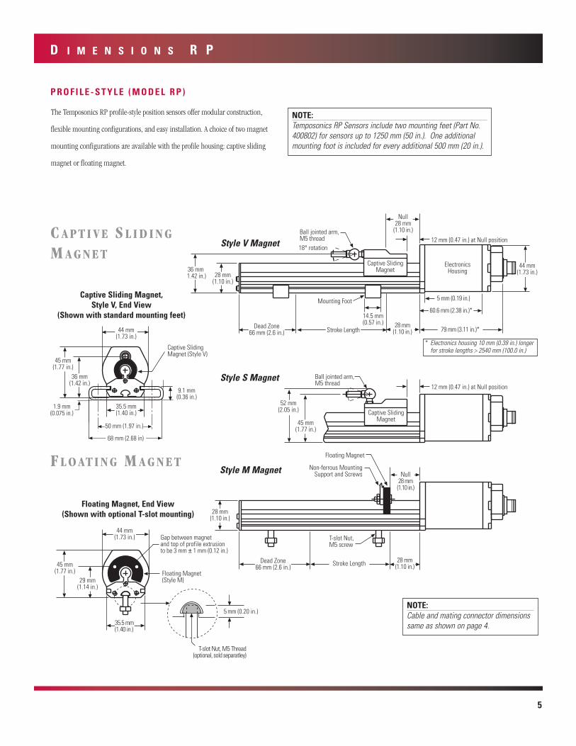
P R O F I L E - S T Y L E ( M O D E L R P )
C A P T I V E S L I D I N G
M A G N E T
F L O AT I N G M A G N E T
Captive SlidingMagnet45 mm
(1.77 in.)
52 mm(2.05 in.)
Ball jointed arm,M5 thread 12 mm (0.47 in.) at Null position
Captive SlidingMagnet (Style V)
9.1 mm(0.36 in.)
1.9 mm(0.075 in.)
68 mm (2.68 in)
35.5 mm(1.40 in.)
36 mm(1.42 in.)
45 mm(1.77 in.)
44 mm(1.73 in.)
50 mm (1.97 in.)
Floating Magnet(Style M)
T-slot Nut, M5 Thread(optional, sold separatley)
Gap between magnetand top of profile extrusionto be 3 mm ± 1 mm (0.12 in.)
35.5 mm(1.40 in.)
44 mm(1.73 in.)
45 mm(1.77 in.)
5 mm (0.20 in.)
29 mm(1.14 in.)
Style V Magnet
Style S Magnet
Style M Magnet
Captive Sliding Magnet,Style V, End View
(Shown with standard mounting feet)
Floating Magnet, End View(Shown with optional T-slot mounting)
NOTE:Cable and mating connector dimensions same as shown on page 4.
The Temposonics RP profile-style position sensors offer modular construction,
flexible mounting configurations, and easy installation. A choice of two magnet
mounting configurations are available with the profile housing: captive sliding
magnet or floating magnet.
NOTE:Temposonics RP Sensors include two mounting feet (Part No.400802) for sensors up to 1250 mm (50 in.). One additionalmounting foot is included for every additional 500 mm (20 in.).
* Electronics housing 10 mm (0.39 in.) longerfor stroke lengths > 2540 mm (100.0 in.)
27295 8/11/03 7:42 AM Page 5

6
W I R I N G
S E N S O R I N T E G R A L C O N N E C T O R ( D 6 0 / D 6 2 M a l e ) :
P i n o u t / W i r e C o l o r C o d e ( I n t e g r a l o r E x t e n s i o n C a b l e )
Pin No. Wire Color Function1 Gray CAN-L (dominant low)2 Pink CAN-H (dominant high)3 Yellow No Connection4 Green No Connection5 Red or Brown + 24 Vdc, (Customer supplied)6 White DC Ground
M A G N E T S
C A B L E C O N N E C T O R S ( F i e l d - i n s t a l l a b l e D 6 F e m a l e )M a t e s w i t h S e n s o r ’s I n t e g r a l C o n n e c t o r
ID: 13.5 mm (0.53 in.)OD: 25.4 mm (1.0 in.)Thickness: 7.9 mm (0.312 in.)(For use with strokes≤ 3050 mm or 120 in.)
Ring MagnetPart No. 400533
Integral D60 Connector (Male) orIntegral D62 Dual Connectors (Both Male)
(As Viewed from End of Sensor)
Cable Length Limitations
Baud Rate MaximumBus Distance
1.0 MBd 80 ft. (25 m)500 kBd 320 ft. (100 m)250 kBd 820 ft. (250 m)125 kBd 1640 ft. (500 m)
18° rotation24 mm
(0.95 in.)
22 mm(0.87 in.)
14 mm(0.55 in.)
9 mm(0.35 in.)
40 mm(1.58 in.)
Ball jointed arm,M5 thread
Rotation:Vertical: 18°
Horizontal: 360°24 mm
(0.95 in.)
37 mm(1.46 in.)
14 mm(0.55 in.)
40 mm(1.58 in.)
35 mm(1.38 in.)
Ball jointed arm,M5 thread
Captive Sliding Magnet, Style VPart No. 252111-1
Captive Sliding Magnet, Style SPart No. 252110-1Magnets must be ordered separately with Temposonics RH sen-
sors. The standard ring magnet (Part No. 201542) is suitable
for most applications.
Magnets are included with the order of the Temposonics
RP sensors. The Temposonics RP can be configured with one
of two magnet configurations: captive sliding magnet or
floating magnet.
4 Holeseach 3.9 mm dia. (0.15 in.)90° apart on 23.9 mm dia. (0.94 in.)
Magnet Spacer(Non-ferrous Spacer forUse with Standard Ring
Magnet)Part No. 400633
Standard Ring MagnetPart No. 201542
4 Holeseach 3.9 mm dia. (0.15 in.)90° apart on 23.9 mm dia. (0.94 in.)
120°
25 mm(0.99 in.)
2 Holeseach 3.9 mm dia. (0.15 in.)on 23.9 mm dia. (0.94 in.)
14 mm(0.57 in.)
20.7 mm(0.81 in.)
Floating Magnet, Style M(May be used
with Temposonics RHand RP)
Part No. 251416
1
2 34
56
D6 Straight-exit ConnectorPart No. 560700
54 mm(2.1 in.)
37 mm (1.5 in)
18 mm(0.7 in.)
54 mm (2.1 in.)
D6 90° ConnectorPart No. 560778
NOTE:Appropriate grounding of cable shield is required at the controller end.
ID: 13.5 mm (0.53 in.)OD: 32.8 mm (1.29 in.)Thickness: 7.9 mm (0.312 in.)
ID: 13.5 mm (0.53 in.)OD: 32.8 mm (1.29 in.)Thickness: 7.9 mm (0.312 in.)
ID: 14.3 mm (0.56 in.)OD: 31.8 mm (1.25 in.)Thickness: 3.2 mm (0.125 in.)
27295 8/11/03 7:42 AM Page 6
H O W T O O R D E R
7
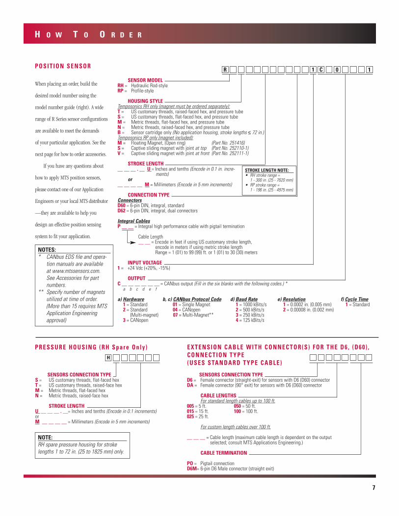
P O S I T I O N S E N S O R
When placing an order, build the
desired model number using the
model number guide (right). A wide
range of R Series sensor configurations
are available to meet the demands
of your particular application. See the
next page for how to order accessories.
If you have any questions about
how to apply MTS position sensors,
please contact one of our Application
Engineers or your local MTS distributor
—they are available to help you
design an effective position sensing
system to fit your application.
NOTE:RH spare pressure housing for strokelengths 1 to 72 in. (25 to 1825 mm) only.
SENSOR MODELRH = Hydraulic Rod-styleRP = Profile-style
HOUSING STYLETemposonics RH only (magnet must be ordered separately):T = US customary threads, raised-faced hex, and pressure tubeS = US customary threads, flat-faced hex, and pressure tubeM = Metric threads, flat-faced hex, and pressure tubeN = Metric threads, raised-faced hex, and pressure tubeB = Sensor cartridge only (No application housing, stroke lengths ≤ 72 in.)Temposonics RP only (magnet included):M = Floating Magnet, (Open ring) (Part No. 251416)S = Captive sliding magnet with joint at top (Part No. 252110-1)V = Captive sliding magnet with joint at front (Part No. 252111-1)
STROKE LENGTH__ __ __ . __ U = Inches and tenths (Encode in 0.1 in. incre-
ments)or
__ __ __ __ M = Millimeters (Encode in 5 mm increments)
CONNECTION TYPEConnectorsD60 = 6-pin DIN, integral, standardD62 = 6-pin DIN, integral, dual connectors
Integral CablesP __ __ = Integral high performance cable with pigtail termination
Cable Length__ __ = Encode in feet if using US customary stroke length,
encode in meters if using metric stroke lengthRange = 1 (01) to 99 (99) ft. or 1 (01) to 30 (30) meters
INPUT VOLTAGE1 = +24 Vdc (+20%, -15%)
OUTPUTC __ __ __ __ __ __ = CANbus output (Fill in the six blanks with the following codes.) *
a) Hardware b, c) CANbus Protocol Code d) Baud Rate e) Resolution f) Cycle Time1 = Standard 01 = Single Magnet 1 = 1000 kBits/s 1 = 0.0002 in. (0.005 mm) 1 = Standard2 = Standard 04 = CANopen 2 = 500 kBits/s 2 = 0.00008 in. (0.002 mm)
(Multi-magnet) 07 = Multi-Magnet** 3 = 250 kBits/s3 = CANopen 4 = 125 kBits/s
a b c d e f
SENSORS CONNECTION TYPES = US customary threads, flat-faced hexT = US customary threads, raised-face hexM = Metric threads, flat-faced hexN = Metric threads, raised-face hex
STROKE LENGTHU __ __ __ . __= Inches and tenths (Encode in 0.1 increments)orM __ __ __ __ = Millimeters (Encode in 5 mm increments)
P R E S S U R E H O U S I N G ( R H S p a r e O n l y )
H
R 1C 01
STROKE LENGTH NOTE:• RH stroke range =
1 - 300 in. (25 - 7620 mm)• RP stroke range =
1 - 196 in. (25 - 4975 mm)
NOTES:* CANbus EDS file and opera-
tion manuals are availableat www.mtssensors.com.See Accessories for part numbers.
** Specify number of magnetsutilized at time of order.(More than 15 requires MTSApplication Engineeringapproval)
SENSORS CONNECTION TYPED6 = Female connector (straight-exit) for sensors with D6 (D60) connectorDA = Female connector (90° exit) for sensors with D6 (D60) connector
CABLE LENGTHSFor standard length cables up to 100 ft.
005 = 5 ft. 050 = 50 ft.015 = 15 ft. 100 = 100 ft.025 = 25 ft.
For custom length cables over 100 ft.
__ __ __ = Cable length (maximum cable length is dependent on the outputselected; consult MTS Applications Engineering.)
CABLE TERMINATION
PO = Pigtail connectionD6M= 6-pin D6 Male connector (straight exit)
E X T E N S I O N C A B L E W I T H C O N N E C T O R ( S ) F O R T H E D 6 , ( D 6 0 ) ,C O N N E C T I O N T Y P E( U S E S S TA N D A R D T Y P E C A B L E )
27295 8/11/03 7:42 AM Page 7

50 mm (1.97 in.)
68 mm(2.68 in)
9.1 mm(0.36 in.)
9.1 mm(0.36 in.)
0.213 in. dia.through 4 holes
304 SST
27.9 mm(1.1 in.)
1.9 mm(0.075 in.)
Width = 14.5 mm (0.57 in.)
42.7 mm (1.68 in)
57 mm (2.25 in.)
0.147 in. dia.through 4 holes
1.3 mm(0.05 in.)
2.5 mm (0.10 in.)
6063-T5Aluminum
27.9 mm(1.1 in.)
9.1 mm(0.36 in.)
1.9 mm(0.075 in.)
Width = 12.7 mm (0.50 in.)
Mounting FeetStandard Mounting Foot
Part No. 400802
14 mm(0.55 in.)
M5 threads
Rotation: 18˚allowable
9 mm(0.35 in.)
M5 insidethread(2) (1)
22 mm(0.87 in.) 27 mm
(1.06 in.)
mUNITED STATESMTS Systems CorporationSensors Division3001 Sheldon DriveCary, NC 27513Tel: 800.633.7609Fax: 919.677.0200Web: www.mtssensors.comEmail:[email protected]
GERMANYMTS Systems CorporationSensors TechnologieAuf dem Schuffel 9, D-58513 Lüdenscheid, GermanyPostfach 8130 D-58489 Lüdenscheid, GermanyTel: + 49.2351.95870Fax: + 49.2351.56491Web: www.mtssensor.de
JAPANMTS Systems CorporationSensors Technologie JapanUshikubo Bldg.737 Aihara-cho, Machida-shiTokyo 194-0211, JapanTel: + 81 (42) 775.3838Fax:+ 81 (42) 775.5512
Pioneers,
Innovators,
Leaders in
Magnetostrictive
Sensing
SENSORSG R O U P
MTS is a registered trademark of MTS Systems Corporation Part Number: 6-03 550541 Revision GTemposonics is a registered trademark of MTS Systems Corporation.
© 2003 MTS Systems CorporationAll Temposonics sensors are covered by US patent number 5,545,984 and others. Additional patents are pending.All other trademarks are the property of their respective owners.
H O W T O O R D E R
O P T I O N A L E X T E N S I O N R O D S ( f o r u s e w i t h C a p t i v e S l i d i n g M a g n e t )Extension Rod Lengths Part No.
60.3 mm (2.375 in.) 401768-2
85.7 mm (3.375 in.) 401768-3
111.1 mm (4.375 in.) 401768-4
161.9 mm (6.375 in.) 401768-6
187.3 mm (7.375 in.) 401768-7
212.7 mm (8.375 in.) 401768-8
238.1 mm (9.375 in.) 401768-9
263.5 mm (10.375 in.) 401768-10
314.3 mm (12.375 in.) 401768-12
365.1 mm (14.375 in.) 401768-14
Extension Rod Lengths Part No.
390.5 mm (15.375 in.) 401768-15
466.7 mm (18.375 in.) 401768-18
517.5 mm (20.375 in.) 401768-20
542.9 mm (21.375 in.) 401768-21
619.1 mm (24.375 in.) 401768-24
771.5 mm (30.375 in.) 401768-30
923.9 mm (36.375 in.) 401768-36
1076.3 mm (42.375 in.) 401768-42
1228.7 mm (48.375 in.) 401768-48
1533.5 mm (60.375 in.) 401768-60
9.5 mm(0.375 in.)
M5-0.8 Thread Bore(both ends)
15.2 mm(0.60 in.)(both ends)
Extension RodPart No. 401768-XX
A C C E S S O R I E S
Description Part No. NotesO-Ring (spare) 560315 For use with Temposonics RH sensorsHex Jam-nut (w/ 3/4-16 UNF threads) 500015 For use with Temposonics RH sensorsHex Jam-nut (w/ M18 x 1.5 threads) 500018 For use with Temposonics RH sensorsMagnet Spacer 400633 For use with Standard Ring Magnet Part No. 201542Magnet Mounting Screws 560357 Used to mount Standard Ring Magnet Part No. 201542
(4 screws required) Floating Magnet, Style M 251416 Spare for Temposonics RP sensorsCaptive Sliding Magnet, Style V 252111-1 Spare for Temposonics RP sensors, Rod joint at front of magnetCaptive Sliding Magnet, Style S 252110-1 Spare for Temposonics RP sensors, Rod joint at top of magnetJoint Rod Sleeve 401603 Optional accessory for Temposonics RP sensorsBall jointed arm 401913 Optional accessory for Temposonics RP sensorsPower Supply (24/28 Vdc, 0.5 A) 380009 Open frame styleMounting Feet, Standard (spares for RP sensors) 400802 Temposonics RP sensors are provided with Mounting Feet,
see page 3Mounting Feet, Low-profile 400867 Optional accessory for Temposonics RP sensorsT-slot M5 Nut 401602 Optional accessory for mounting Temposonics RP sensorsD6 Field-installable Connector 560700 Female, straight-exit, see page 6D6 Field-installable Connector 560778 Female, 90°, see page 6Cable, Standard type 530026 3 twisted pairs, shielded, PVC jacket, specify desired
length in feet.Cable, high performance type 530029 7 conductor, EMC shielded; oil resistant jacket. Specify desired
length in feet.Operation Manual, Single Magnet CANbus 550744 Available at www.mtssensors.comOperation Manual, Multi-magent CANbus 550755 Available at www.mtssensors.comOperation Manual, CANOpen 991005 Available at www.mtssensors.com
Low-profile Mounting FootPart No. 400867
Joint RodUsed with Captive Sliding Magnets
(1) Sleeve, Part No. 401603(2) Ball jointed arm, Part No. 401913
27295 8/11/03 7:42 AM Page 8