samba printhead materials compatibility kit instructions
TRANSCRIPT

FUJIFILM Dimatix, Inc. Confidential and Proprietary Information Doc. #IN000084 Rev. 15P/N 2100300368 June 2, 2021
Samba® Printhead Materials Compatibility Kit Instructions –
P/N 2100201341
The enclosed samples are for testing the compatibility of the materials in the Samba printhead with the jetting or flushing fluids that will be used.
It is important to understand the intended purpose of the materials compatibility kit (MCK) and the test instructions. It is meant to be primarily a “fast-fail” test that highlights the instances when there are gross or severe incompatibilities between fluids and printhead components. The testing results here are designed to show failures and cannot reliably predict long-term success or service lifetime.
For this reason there are only failure criteria listed for each test. The lack of a failure of a test should be interpreted as “no failure” rather than “passing lifetime testing”. It is at the sole discretion of the user to interpret the significance of any test result from the use of the MCK. Please contact FUJIFILM Dimatix with any questions regarding procedures described herein.
2 Samba Printhead MCK Instructions
Doc. #IN000084 Rev. 15 FUJIFILM Dimatix, Inc. Confidential and Proprietary InformationJune 2, 2021 P/N 2100300368
1.0 Overall Test Format
The following test procedures describe the basic approach to compatibility testing used in the MCK - P/N 2100201341. The enclosed selection of parts and materials are soaked in the fluids they come in contact with (or have potential contact with). Physical characteristics of the materials are observed and recorded and any changes that occur over a three month soak period are to be noted. The suggested intervals for the soak testing requires observations at 1 week, 1 month, and 3 months.
The MCK is configured as individually packaged pieces of each material; there are three of each piece included in the MCK. Use one piece as a baseline control, one piece for testing with the ink or jetting fluid, and one piece for testing with the flush fluid. For more data each test should be done multiple times so an average outcome can be determined. All jetting fluids and flush fluids that are intended for use need to be evaluated.
When testing for compatibility, it is important that individual colors of the ink also be tested as there could be effects that individual color components may have on the materials in the ink path on the printhead. In such cases where multiple ink colors are to be tested, two MCKs allow for testing of a Control, a Flush, and four colors (e.g. cyan, magenta, yellow, and black). In some applications the impact of other process related chemicals that may contaminate the printhead should be considered for testing.
Samba Printhead MCK Instructions 3
FUJIFILM Dimatix, Inc. Confidential and Proprietary Information Doc. #IN000084 Rev. 15P/N 2100300368 June 2, 2021
2.0 MCK Components
The following table lists each of the MCK components part number and physical description, a picture of the part, a reference to the location of its test conditions, and failure criteria.
Table 1 Materials Compatibility Kit Components
Part Description Test Condition Failure Criteria
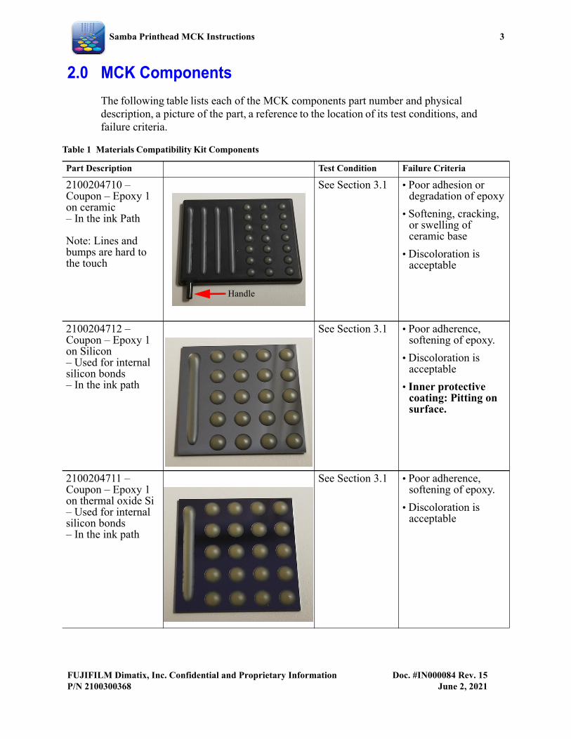
2100204710 – Coupon – Epoxy 1 on ceramic– In the ink Path
Note: Lines and bumps are hard to the touch
See Section 3.1 • Poor adhesion or degradation of epoxy
• Softening, cracking, or swelling of ceramic base
• Discoloration is acceptable
2100204712 – Coupon – Epoxy 1 on Silicon– Used for internal silicon bonds– In the ink path
See Section 3.1 • Poor adherence, softening of epoxy.
• Discoloration is acceptable
• Inner protective coating: Pitting on surface.
2100204711 – Coupon – Epoxy 1 on thermal oxide Si– Used for internal silicon bonds – In the ink path
See Section 3.1 • Poor adherence, softening of epoxy.
• Discoloration is acceptable
Handle

4 Samba Printhead MCK Instructions
Doc. #IN000084 Rev. 15 FUJIFILM Dimatix, Inc. Confidential and Proprietary InformationJune 2, 2021 P/N 2100300368
2100200907 – Coupon – Sealant on ceramic– Used to seal– Not in the ink pathNote: Lines and bumps are slightly spongy or elastic to the touch
See Section 3.1 Sealant on ceramic:• Poor adhesion or
softening of epoxy
• Softening, cracking, or swelling of ceramic base
• Discoloration is acceptable
2100316992 – Coupon – Epoxy 2 on Ceramic– Used on bonds between head mount and dovetail mount– Not in the ink path
Note: Lines and bumps are hard to the touch
See Section 3.1 • Poor adhesion or softening of epoxy
• Softening, cracking, or swelling of ceramic base
• Discoloration is acceptable
2100321444 – Coupon (back) – Side non-wetting coating on ceramic (SNWC)
Note: The SNWC sample is painted on the carbon and will appear shiny
See Section 3.4 Side non-wetting coating on ceramic:• Removal of side non-
wetting coating
• DI water fails to bead on the surface of the side non-wetting coating
Table 1 Materials Compatibility Kit Components
Part Description Test Condition Failure Criteria
Handle
Handle
HandleSNWC
Samba Printhead MCK Instructions 5
FUJIFILM Dimatix, Inc. Confidential and Proprietary Information Doc. #IN000084 Rev. 15P/N 2100300368 June 2, 2021
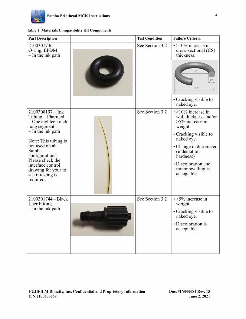
2100301746 – O-ring, EPDM– In the ink path
See Section 3.2 • >10% increase in cross-sectional (CS) thickness.
• Cracking visible to naked eye.
2100308197 – Ink Tubing – Pharmed– One eighteen inch long segment– In the ink path
Note: This tubing is not used on all Samba configurations. Please check the interface control drawing for your to see if testing is required.
See Section 3.2 • >10% increase in wall thickness and/or >5% increase in weight.
• Cracking visible to naked eye.
• Change in durometer (indentation hardness)
• Discoloration and minor swelling is acceptable.
2100301744 – Black Luer Fitting– In the ink path
See Section 3.2 • >5% increase in weight.
• Cracking visible to naked eye.
• Discoloration is acceptable.
Table 1 Materials Compatibility Kit Components
Part Description Test Condition Failure Criteria
6 Samba Printhead MCK Instructions
Doc. #IN000084 Rev. 15 FUJIFILM Dimatix, Inc. Confidential and Proprietary InformationJune 2, 2021 P/N 2100300368
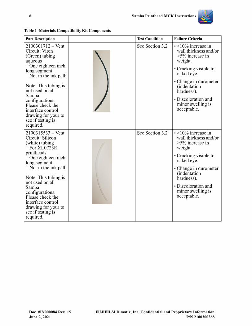
2100301712 – Vent Circuit: Viton (Green) tubingaqueous– One eighteen inch long segment– Not in the ink path
Note: This tubing is not used on all Samba configurations. Please check the interface control drawing for your to see if testing is required.
See Section 3.2 • >10% increase in wall thickness and/or >5% increase in weight.
• Cracking visible to naked eye.
• Change in durometer (indentation hardness).
• Discoloration and minor swelling is acceptable.
2100315533 – Vent Circuit: Silicon (white) tubing– For XL0723R printheads– One eighteen inch long segment– Not in the ink path
Note: This tubing is not used on all Samba configurations. Please check the interface control drawing for your to see if testing is required.
See Section 3.2 • >10% increase in wall thickness and/or >5% increase in weight.
• Cracking visible to naked eye.
• Change in durometer (indentation hardness).
• Discoloration and minor swelling is acceptable.
Table 1 Materials Compatibility Kit Components
Part Description Test Condition Failure Criteria
Samba Printhead MCK Instructions 7
FUJIFILM Dimatix, Inc. Confidential and Proprietary Information Doc. #IN000084 Rev. 15P/N 2100300368 June 2, 2021
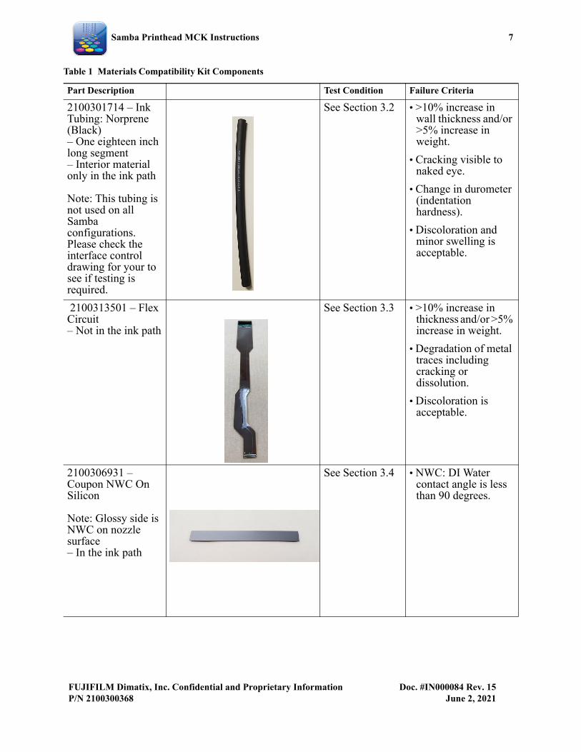
2100301714 – Ink Tubing: Norprene (Black)– One eighteen inch long segment– Interior material only in the ink path
Note: This tubing is not used on all Samba configurations. Please check the interface control drawing for your to see if testing is required.
See Section 3.2 • >10% increase in wall thickness and/or >5% increase in weight.
• Cracking visible to naked eye.
• Change in durometer (indentation hardness).
• Discoloration and minor swelling is acceptable.
2100313501 – Flex Circuit– Not in the ink path
See Section 3.3 • >10% increase in thickness and/or >5% increase in weight.
• Degradation of metal traces including cracking or dissolution.
• Discoloration is acceptable.
2100306931 – Coupon NWC On Silicon
Note: Glossy side is NWC on nozzle surface– In the ink path
See Section 3.4 • NWC: DI Water contact angle is less than 90 degrees.
Table 1 Materials Compatibility Kit Components
Part Description Test Condition Failure Criteria
8 Samba Printhead MCK Instructions
Doc. #IN000084 Rev. 15 FUJIFILM Dimatix, Inc. Confidential and Proprietary InformationJune 2, 2021 P/N 2100300368
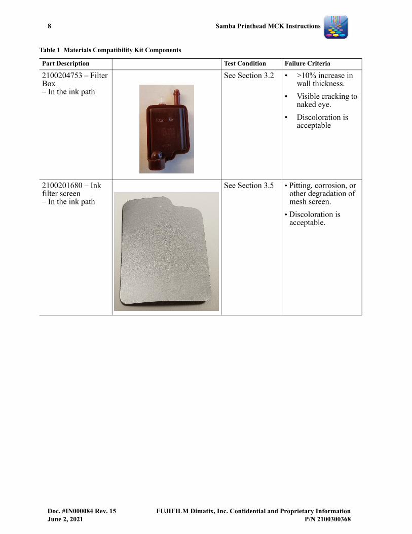
2100204753 – Filter Box– In the ink path
See Section 3.2 • >10% increase in wall thickness.
• Visible cracking to naked eye.
• Discoloration is acceptable
2100201680 – Ink filter screen– In the ink path
See Section 3.5 • Pitting, corrosion, or other degradation of mesh screen.
• Discoloration is acceptable.
Table 1 Materials Compatibility Kit Components
Part Description Test Condition Failure Criteria
Samba Printhead MCK Instructions 9
FUJIFILM Dimatix, Inc. Confidential and Proprietary Information Doc. #IN000084 Rev. 15P/N 2100300368 June 2, 2021
3.0 Compatibility Testing
All fluid soak tests should be performed in a stable, controlled temperature environment set to the proper jetting and flushing temperatures. It is appropriate to run the soak tests at the highest temperature that the printhead is expected to experience during operation, e.g. usually 2°C higher than the nominal operation temperature.
It is important to remember that the validity and usefulness of these tests depend upon careful observations and accurate measurements. This involves careful baseline assessment of all materials (prior to test) along with repeatable reproducible collection of data at each interval during the test.
3.1 Coupons of Epoxy/Sealant on Various Base Materials
1. Prior to soaking, use a probe to gently check the adhesion of each epoxy bump or line (or for the sealant) to the ceramic base material. (The sealant is a softer material; probe it carefully). Repeat for the silicon and silicon dioxide coupons.
a. Inspect for baseline characteristics of sample.
b. Probe the base material for hardness and scratch resistance.
2. Weigh each coupon to the nearest 0.01 gram if possible, keeping track which one is used for control, jetting fluid, and flushing fluid.
3. Partially submerge each coupon in the fluid to be tested, keeping some of the dispensed line(s) and bumps above the fluid line.
a. Each coupon should have its own container.
b. Be sure to mark which half is not submerged so there is no confusion.
c. For the ceramic base material, select the long edge with “handle” as up and adjust the fluid level near the third row of bumps from the top. This leaves a clear two rows (6 bumps) above the fluid and four rows (12 bumps) submerged.
d. For the silicon and thermal oxide coupons, a fluid line at the second row of bumps leaves one row (4 bumps) above and three rows (12 bumps) submerged.
4. After the first week of soak remove the coupon(s), briefly rinse with a compatible flush fluid, then thoroughly (but gently) wipe dry. Check the sample for weight changes, line and bump adhesion, and softening of the epoxy. Check the ceramic base material for changes in thickness and hardness. Compare epoxy or sealant softening to the corresponding control sample and compare submerged materials to those above the fluid line.
a. Inspect for changes or abnormalities such as pitting.
10 Samba Printhead MCK Instructions
Doc. #IN000084 Rev. 15 FUJIFILM Dimatix, Inc. Confidential and Proprietary InformationJune 2, 2021 P/N 2100300368
b. To check bump adhesion, select specific bumps to monitor throughout the test. Monitor one bump above the soak line, one bump in the soak line, and three bumps that are submerged.
c. When checking the line adhesion, select a consistent part of the line above the fluid, at the soak line, and submerged in the fluid to monitor throughout the test.
5. Repeat the test at the end of one month then at the end of three months.
6. For the epoxy and sealant samples the bumps and lines (on all base materials) should be well adhered and not softening. For the ceramic base materials, no change in weight or thickness should be found and no softening should occur.
3.2 O-Ring, Tubing, Luer Lock, Filter Box
1. Record the initial weight of the Viton (green) tubing, O-ring and Luer Lock fitting. In addition, for the green Viton tubing accurately measure the internal diameter (ID), outer diameter (OD) and Durometer. Record the cross-sectional diameter of the O-ring.
a. All components should be fully submerged in fluid and placed in an oven at jetting temperature.
2. Cut Pharmed and Norprene tubing samples into 2’ sections and measure the ID, OD and Durometer. Insert barbed Luer fittings into the ends of the cut tubing samples. Use a syringe to fill the tubing samples with test fluid then insert the Luer cap fittings (other methods of capping the tubing may be suitable in place of Luer fittings). Measure the filled weight of each tubing sample.
a. Place filled tubing samples in an oven at jetting temperature.
3. Remove the sample after one week. Rinse, wipe, and dry the sample. Blow out the inside of the samples with compressed dry air or dry nitrogen to remove any fluid from the interior. Weigh the samples to determine any weight change. No weight change greater than ±10% should be seen. Measure durometer, ID, and OD of the tubing and cross-sectional diameter of the O-ring. No changes in diameter measurements greater than ±10% should be seen.
4. Repeat the test at the end of the first month then at the end of three months time.
3.3 Flex Circuit
1. Using scissors, cut out the narrow section of the polyimide flex circuit strip. Choose one sample for control and one each for jetting and flushing fluid.
Samba Printhead MCK Instructions 11
FUJIFILM Dimatix, Inc. Confidential and Proprietary Information Doc. #IN000084 Rev. 15P/N 2100300368 June 2, 2021
2. Weigh each flex section and record the data. Measure the thickness of each flex section with calipers. Choose a particular location that can be found for subsequent measurements. Connect the two ends of the flex together with a paper clip, then submerge each loop in the appropriate fluid, but keep the two cut ends above the fluid line.
3. Remove the sample after one week and record the weight and thickness.
4. Repeat the test at the end of the first month and then at the end three months time.
5. At each step, record the thickness and weight of the flex. Any changes (increases) greater than ±10% in thickness or ±10% in weight relative to the baseline might indicate absorption of fluid. Observe the soaked area of the flex strip to look for any color changes. Color change at the edges of the flex might indicate fluid ingress into the epoxy bond.
6. Optional: The metal traces could be surveyed for degradation, cracking, etc. using a Scanning Electron Microscope. If possible, this should be done at each interval, or sooner if there is any weight gain or swelling which has occurred.
7. Although some color staining may be seen, there should be no degradation of the metal traces or any significant change in the polyimide thickness. It is important to examine the integrity of the adhesive bonding of the polyimide flex to the internal copper traces to look for any softening, swelling, or degradation from the baseline.
3.4 Non Wetting Coating and Side Non Wetting Coating (NWC, SNWC)On Silicon Test
Performing this test requires a VCA (Video Contact Angle) tool. Test the NWC by soaking the material at the jetting temperature within a Polyethylene (PE) beaker, keeping the samples partially submerged in the jetting and flush fluids. Use a PE beaker instead of glass as glass can serve as a sacrificial material for silicon.The beaker should be covered by a High-density Polyethylene (HDPE) bottle to prevent evaporation. The fluids should be refreshed weekly during testing. To accelerate the test, it is generally acceptable to test at jetting temperature as well as jetting temperature +10 degrees Celsius, but any elevated temperature above jetting temperature should be discussed with the fluid supplier to ensure that the fluid doesn’t break down and cause adverse affects. We recommend that you get pH stability data over time at all the temperatures to be tested.
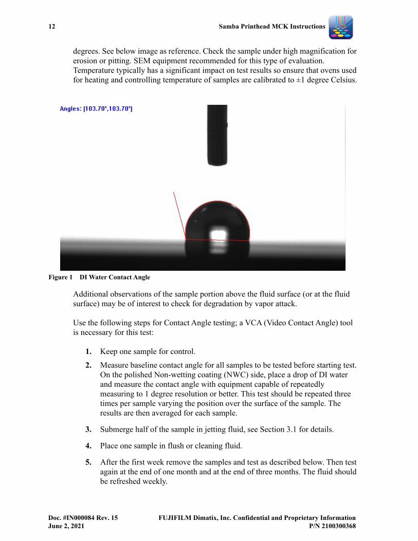
The process, which is outlined on the following page, has you remove the samples at the specified periodic intervals for observation by removing the part from the fluid and gently blotting with a clean room wipe. Rinse with your flush and gently blot dry, then rinse with a small amount of isopropyl alcohol (IPA) and blot dry. On the polished side of the coupon test the DI water contact angle on the submerged portion, which should be greater than 90
12 Samba Printhead MCK Instructions
Doc. #IN000084 Rev. 15 FUJIFILM Dimatix, Inc. Confidential and Proprietary InformationJune 2, 2021 P/N 2100300368
degrees. See below image as reference. Check the sample under high magnification for erosion or pitting. SEM equipment recommended for this type of evaluation. Temperature typically has a significant impact on test results so ensure that ovens used for heating and controlling temperature of samples are calibrated to ±1 degree Celsius.
Figure 1 DI Water Contact Angle
Additional observations of the sample portion above the fluid surface (or at the fluid surface) may be of interest to check for degradation by vapor attack.
Use the following steps for Contact Angle testing; a VCA (Video Contact Angle) tool is necessary for this test:
1. Keep one sample for control.
2. Measure baseline contact angle for all samples to be tested before starting test. On the polished Non-wetting coating (NWC) side, place a drop of DI water and measure the contact angle with equipment capable of repeatedly measuring to 1 degree resolution or better. This test should be repeated three times per sample varying the position over the surface of the sample. The results are then averaged for each sample.
3. Submerge half of the sample in jetting fluid, see Section 3.1 for details.
4. Place one sample in flush or cleaning fluid.
5. After the first week remove the samples and test as described below. Then test again at the end of one month and at the end of three months. The fluid should be refreshed weekly.
Samba Printhead MCK Instructions 13
FUJIFILM Dimatix, Inc. Confidential and Proprietary Information Doc. #IN000084 Rev. 15P/N 2100300368 June 2, 2021
a. Examine the NWC (polished) side for visual changes.
b. Examine reverse side for visual changes.
c. On the polished NWC side, place a drop of DI water and measure the contact angle with equipment capable of repeatedly measuring to 1 degree resolution or better. This test should be repeated three times per sample varying the position over the surface of the sample. The results are then averaged for each sample. The contact angle should be greater than 90 degrees.
Use the following steps for wear (Taber) testing if contact maintenance techniques are planned for the printhead application:
1. Use two samples for wear testing, using the appropriate wipe material and ink, flush, or cleaning fluid, wiping force, and number of wipe cycles that is intended for the printhead application.
2. Data should be collected at appropriate intervals for the scope of testing typically intervals no larger than 25% of the number of test cycles.
3. On the polished NWC coating side that has been wear tested, place a drop of DI water and measure the contact angle with equipment capable of repeatedly measuring to 1 degree resolution or better. The contact angle should be greater than 90 degrees. This test should be repeated three times per sample varying the position over the surface of the sample. The results are then averaged for each sample.
Streaking may be due to improper wiping and should not be confused with coating quality. Scratches and chips are caused by improper handling of silicon material and are not material failure. Physical damage to the silicon sample may damage the coating and adversely affect the coating testing. Deposition or ink drying on the sample can also affect the contact angle.
When testing for compatibility improvements, comparative testing is best. Conduct testing using current and proposed fluid formulation.
3.5 Ink Filter Screen
Three samples are provided; use one sample for control, one sample for jetting fluid, and one sample for flushing fluid.
1. Inspect the filter screen and note any surface irregularities (pits, bumps) as well as any discoloration such as inclusions in the screen. Photograph at 200x or 1000x. SEM imaging is preferred to obtain the baseline image information.
14 Samba Printhead MCK Instructions
Doc. #IN000084 Rev. 15 FUJIFILM Dimatix, Inc. Confidential and Proprietary InformationJune 2, 2021 P/N 2100300368
2. The filter should be partially submerged in the ink or flush during the test. Testing should be done at jetting temperature.
3. Remove screen from the fluid after one week. Visually check for any degradation, pitting, or any signs of corrosion under 200x (compound microscope; use SEM if damage is observed) visual magnification and/or 1000x magnification in the SEM. Take images for comparison to baseline images. Check both the submerged and the transition area.
4. Repeat at the end of the first month and at the end of three months.
3.6 Other Testing
Testing should also include the monitoring of fluid properties such as color, viscosity, pH, and filtration that may be affected by exposure to the various materials. Fluids and flushes that have not been tested may be used as controls. We suggest testing these attributes at the end of the test period for comparison to the baseline values. In the case of time dependent or perishable fluids such as UV inks, the fluids may require replacement during the testing.
Additionally, all components that are part of the fluid delivery system such as tubing, filters, and valves must be tested for compatibility with the fluids that they are to come in contact with.
FUJIFILM Dimatix can be contracted to conduct these tests. Contact your account representative to make arrangements. Once the work has been ordered send 300 cc of your fluid, flush fluid, and any storage solution to Dimatix using the fluid submission process. If you are unfamiliar with our FRA process, please contact your Customer Service representative for assistance. Also see IN000064, How To Package Ink When Shipping To FUJIFILM Dimatix, for packing and shipping instructions and IN000099: Fluid Receiving Authorization Form Instructions both available in the Team Support Customer Portal. Samples will be tested and a report will be generated and returned to you.
If any results or observations seem questionable, feel free to send those materials to Dimatix for evaluation.
In our continuing effort to provide robust printheads, FUJIFILM Dimatix is striving to understand the compatibility of our component materials with fluids and materials most desired by our customers. Toward that end, should you wish to share your test results with us they would be considered confidential and for internal use only.