safety switches - cloud object storage | store ... switches heavy duty — 600v ac, 10,000 &...
TRANSCRIPT
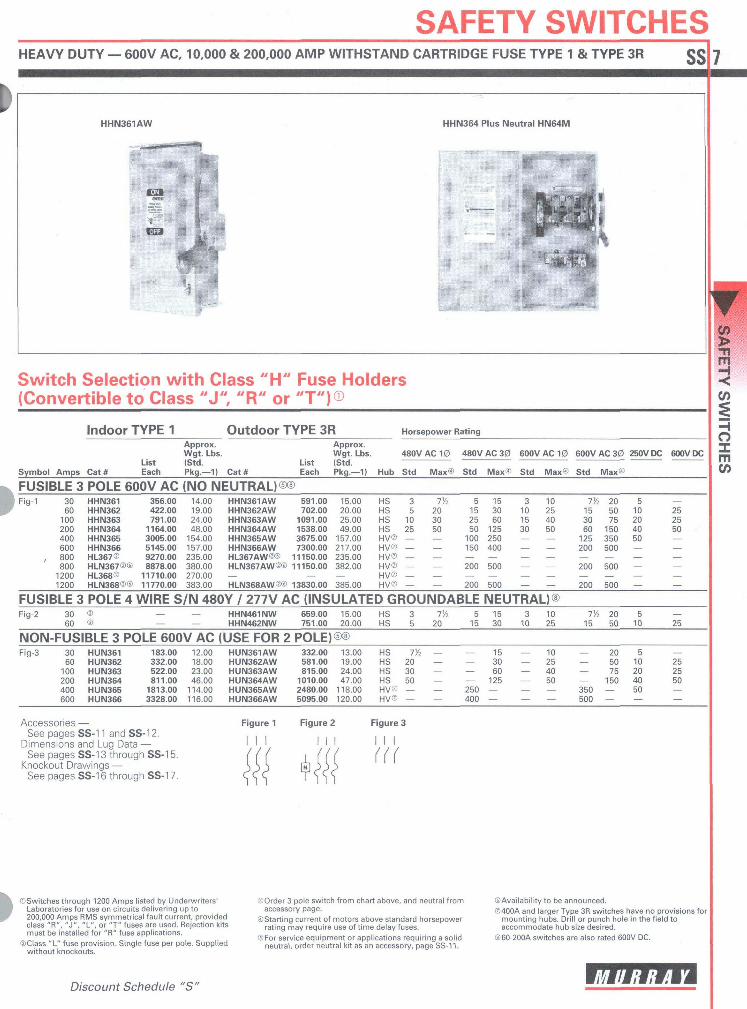
SAFETY SWITCHESHEAVY DUTY — 600V AC, 10,000 & 200,000 AMP WITHSTAND CARTRIDGE FUSE TYPE 1 & TYPE 3R
HHN361AW HHN364 Plus Neutral HN64M
Switch Selection with Class "H" Fuse Holders(Convertible to Class "J" "R" or "T")®
IndOOr TYPE 1 Outdoor TYPE 3R Horsepower RatingApprox. Approx.Wgt. Lbs. Wgt. Lbs. 480V AC 10
List (Std. List (Std.Symbol Amps Cat# Each Pkg.— 1) Cat# Each Pkg.— 1) Hub Std Max®
480V AC 30
Std Max®
600V AC 10
Std Max®
600V AC 30
Std Max®
250V DC 600V DC
FUSIBLE 3 POLE 600V AC (NO NEUTRAL)®®Fig-1 30 HHN361 356.00 14.00 HHN361AW 591.00 15.00 HS 3 7!/2
60 HHN362 422.00 19.00 HHN362AW 702.00 20.00 HS 5 20100 HHN363 791.00 24.00 HHN363AW 1091.00 25.00 HS 10 30200 HHN364 1164.00 48.00 HHN364AW 1538.00 49.00 HS 25 50400 HHN365 3005.00 154.00 HHN365AW 3675.00 157.00 HV® — —600 HHN366 5145.00 157.00 HHN366AW 7300.00 217.00 HV® — —
, 800 HL367® 9270.00 235.00 HL367AW®® 11150.00 235.00 HV® — —800 HLN367®® 8878.00 380.00 HLN367AW®® 11150.00 382.00 HV® — —
1200 HL368® 11710.00 270.00 — — — HV® — —1200 HLN368®® 11770.00 383.00 HLN368AW®® 13830.00 385.00 HV® — —
51 52550
100150
200
200
FUSIBLE 3 POLE 4 WIRE S/N 480Y / 277V AC (INSULATED GROUNDABLEFig-2 30 ® — — HHN461NW 659.00 15.00 HS 3 1%
60 ® — — HHN462NW 751.00 20.00 HS 5 205
1 5
1 53060
125250400
500
500
3 1010 2515 4030 50
7!/2
1 53060
125200
200
200
205075
150350500
500
500
5 —10 2520 2540 5050 —
NEUTRAL)®1 530
3 1010 25
7%1 5
2050
5 —10 25
NON-FUSIBLE 3 POLE 600V AC (USE FOR 2 POLE)®®Fig-3 30 HUN361 183.00 12.00 HUN361AW 332.00 13.00 HS Th —
60 HUN362 332.00 18.00 HUN362AW 581.00 19.00 HS 20 —100 HUIM363 522.00 23.00 HUN363AW 815.00 24.00 HS 30 —200 HUN364 811.00 46.00 HUN364AW 1010.00 47.00 HS 50 —400 HUIM365 1813.00 114 .00 HUN365AW 2480.00 118.00 HV® — —600 HUN366 3328.00 116 .00 HUN366AW 5095.00 120.00 HV® — —
250400
1 53060
125
— 10— 25— 40— 50
350500
205075
150
5 —10 2520 2540 5050 —
Accessories — Figure 1 Figure 2 Figure 3See pages SS-1 1 and SS-1 2.
Dimensions and Lug Data — / / / / /See pages SS-1 3 through SS-1 5. fff \ {({ (((
Knockout Drawings — 333 H 333See pages SS-1 6 through SS-1 7. CCC T S S S
rv SWITCHES
©Switches through 1200 Amps listed by Underwriters'Laboratories for use on circuits delivering up to200,000 Amps RMS symmetrical fault current, providedclass "R", "J", "L", or "T" fuses are used. Rejection kitsmust be installed for "R" fuse applications.
©Class "L" fuse provision. Single fuse per pole. Suppliedwithout knockouts.
Discount Schedule "S"
©Order 3 pole switch from chart above, and neutral fromaccessory page.
©Starting current of motors above standard horsepowerrating may require use of time delay fuses.
©For service equipment or applications requiring a solidneutral, order neutral kit as an accessory, page SS-11.
©Availability to be announced.©400A and larger Type 3R switches have no provisions for
mounting hubs. Drill or punch hole in the field toaccommodate hub size desired.
©60-200A switches are also rated 600V DC.

SAFETY SWITCHESTECHNICAL INFORMATION ss 3
General Duty Switches; Prefix "G"General duty switches are available in indoorTYPE 1 and outdoor TYPE 3R enclosures.Enclosures can be locked closed and operatinghandles can be locked "OFF". Series "G"switches have a quick-make, quick-breakmechanism. Fusible switches are available in1 pole S/N, 2 pole S/N and 3 pole S/Nconfigurations. Non-fusible switches areavailable in 2 pole and 3 pole configurations.General duty switches are limited to 240V AC,600 Amps max. rating.All 30 Amp compact fusible and non-fusible"G" prefix switches are rated 10,000 Ampmaximum withstand.
All 30-600 Amp "GF" and "GU" prefixswitches are suitable for use on systemscapable of delivering not more than 100,000RMS symmetrical Amps of fault current withClass "R" fuses and the appropriate adapterkit installed. These 100-600 Amp "G" prefixswitches may also be used on systems capableof delivering not more than 100,000 RMSsymmetrical Amps of fault current with "T"fuses and the appropriate adapter kit installed.In addition, 200-600 general duty switchesmay also be used with J fuses on systemsnot capable of delivering more than 100,000RMS symmetrical amperes of fault current.General duty switches are UL Listed for useas service equipment and are horsepowerrated for use with motor loads.
General duty enclosed switches are used forlight duty applications where loading andswitching operations are not excessive.
Heavy Duty Switches, SingleThrow; Prefix "H"Heavy duty switches are available in indoorTYPE 1, outdoor TYPE 3R, Watertight Type4/4X, and industrial TYPE 12 enclosures. Dualcover interlocks are provided, such that thedoor cannot be opened with the switch "ON"and the switch cannot be turned "ON" withthe door open. A defeat mechanism allowsservicing by authorized personnel. Handlesmay be locked "OFF" with up to 3 padlocks,and doors may be padlocked closed.Mechanism is "TEASE-PROOF" quick-make,quick-break. Fusible switches are available in 2pole S/N, 3 pole and 3 pole S/N. Non-fusibleswitches are available in 3 pole.Suitable for use on systems capable ofdelivering not more than 200,000 RMSsymmetrical amperes of fault current whenClass "J" or "R" fuses are installed except the800 and 1200A switches, which are suitablefor use on circuits capable of delivering notmore than 200,000 RMS symmetrical amperes
of fault current when Class "L" fuses areinstalled. 100-1200A switches with Class "T"fuses and field adapter kit 200,000 RMSsymmetrical rated.Heavy duty switches are dual horsepowerrated and are listed by UL for use as serviceentrance equipment.Heavy duty switches are intended forapplications where rugged construction,reliable performance, continuity of serviceand ease of maintenance are required.
Protector-Lock® Switches;Prefix "H"The Murray Protector-Lock" switch isdesigned to eliminate shock hazard due todisconnecting heavy duty portable electricalequipment under load. When the switch is inthe "ON" position, the safety bar blocks theself-contained receptacle and preventsinsertion or removal of the plug. When theswitch is "OFF", the bar retracts, allowinginsertion or removal of the plug.Protector-Lock8 switches consist of aheavy duty, 30 or 60 Amp, 600V AC, 3 polefusible or non-fusible enclosed switch, andeither Grouse-Hinds® or Arrow Hart®Industrial receptacles.Applications include industrial plants whereportable conveyors and welders are used, andtruck terminals where on-board refrigerationunits require stand-by power.
Double Throw Switches;Prefix "HD"Double throw switches are available in TYPE 1and TYPE 3R enclosures. Covers are dualinterlocked with the operating mechanismsuch that the cover cannot be opened whenthe switch is in either "ON" position, and theswitch handle cannot be moved to either"ON" position if the cover is open. Handlemay be padlocked in the "OFF" position.Switching action is quick-make, quick-break inboth "ON" positions.They are available in 30-600 Amp ratings,240V AC, fusible and non-fusible, two andthree pole.Double throw switches are usually applied astransfer switches to switch a load from onepower source to another, but can be fieldconverted to switch one power sourcebetween two loads. Switching mechanism islocated on line side of fuses allowing for asafer fuse replacement.
Pullout Switches; Prefix "P"Pullout switches are intended for outdoordisconnect applications, primarily asair-conditioning disconnects. They are housedin TYPE 3R enclosures, with covers which maybe padlocked closed. Pullout heads arecompletely removable for safety whenservicing rotating equipment. They areavailable in fusible (Class "H") and non-fusiblemodels, single phase, 120/240VAC, 30 and60 Amps. Withstand ratings of standard "PE"prefix models is 10,000 Amps RMS Sym.
Industry and GovernmentSpecificationsMURRAY enclosed switches meet or exceedthe latest revision of the followingspecifications:IndustryNEMA
Standard #KS-1UL-Standard #98U.S. Government
HD single throw, prefix "H":Standard #WS-865ctype "HD"
HD double throw, prefix "HD":Standard #WS865ctype "NDD"
GD 60-600 Amp, prefix "G":Standard #WS 865c type "NO";except where interlock is required.
GDSOAmp, prefix "G":Standard #WS-865c type "ND";except where interlock is required.
Arrow Hart® and Grouse-Hinds® are registered trademarksof Cooper Industries, Inc.Protector-Lock* is a registered trademark of MurrayElectrical Products.
CO>Tlm
CO
mCO

SAFETY SWITCHES EDIMENSIONS & LUG DATA, GENERAL & HEAVY DUTY SWITCHES, PROTECTOR-LOCK® SWITCHES, PULLOUT SWITCHES <J<J
Safety Switch Dimensions®Height
WithCatalog Box Door
Number A BHUN362AW 16.26 —HUN362AS 16.27 17.46HUN363 21.95 23.15HUN363AJ 21.96 23.16HUN363AS 21.96 23.16HUN363AW 21.95 —HUN364 29.90 31.07HUN364AJ 29.96 31.07HUN364AS 29.96 31.07HUN364AW 29.90 —HUN365 44.00 44.57HUN365AJ 44.14 44.57HUN365AW 44.07 —HUN366 44.00 44.57HUN366AW 44.07 —
Double Throw SwitchesDimensions®
L W DBox Handle
Cat # (A) (C)HDH321 37 12 12% 6%HDH321AW 37 12 12% 6%HDH322 37 12 12% 6%HDH322AW 37 12 12% 6%HDH323 37 12 12% 6%HDH323AW 37 12 12% 6%HDH324 51% 193/ie 20% 6%HDH324AW 51% 193/ie 20% 6%HDH325 74% 25% 26% 8%HDH326 86 27/2 28% 8%HDH361 37 11% 121/2 4%HDH362 37 11% 12V5 4%HOH363 37 11 % 12V4 4%HDH364 51% 193/i6 20 6VtHDH365 74% 24% 25% 8%HDU221 253/4 12 12% 4%HDU222 25 12 12% 4%HDU223 25 12 12% 4%HDU224 37% 193/ie 20% 6%HDU224AW 37% 193/i6 20% 6%HDU225 54% 23 23% 7%HDU225AW 54% 23 23% 7%HDU321 25 12 12% 4%HDU322 25 12 12% 4%HDU323 25 12 12% 4%HDU323AW 25 12 12% 4%HDU324 37% 193/ie 20% 6%HDU324AW 37% 193/,e 20% 6%HDU325 54V4 23 23% 7%HDU326 63% 24 24% 8%HDU361 25 11% 12'/2 4%HDU361AW 25 11% 12'/2 4%HDU362 25 11% 12V4 5%HDU362AW 25 11% 12'/2 4%HDU363 25 11% 12'/2 6%HDU363AW 25 11% 12'/2 4%HDU364 37% 193/,8 20 6%HDU364AW 377s 193/1B 20 6%HDU365 54% 22% 23'/2 7%HDU365AW 54% 22% 23V4 TAHDU366AW 633/« 23% 241/: 8%HDU367AW 633/4 23% 24% 8%
® Knockouts not provided on Type 4/4X and 12 or on 800 &1200A switches.
Width DepthWith With WithRain Shed Box Handle Box Handle KnnrknutC D E F G Diagram®17.77 9.16 11.53 5.05 10 .17 S17— 9.17 11.47 5.33 10.46 —— 9.64 12.01 5.05 10.17 S10— 9.65 12.02 5.34 10.46 —— 9.65 12.02 5.34 10.46 —
23.46 9.64 11 .97 5.05 10.17 S11— 14.62 16.98 6.36 12.33 S12— 14.62 16.95 6.63 12.58 —— 14.62 16.95 6.63 12.58 —31.42 14.61 16.99 6.36 12.33 S13
— 24.64 26.21 9.23 14.68 S14— 24.82 26.44 9.19 14.64 —45.19 24.64 26.95 9.23 14.68 S15— 24.64 26.21 9.23 14.68 S1445.19 24.64 26.95 9.23 14.68 S15
General & Heavy Duty SwitchesLug Data30-1 OOA Switches are suitable for use with 60° or 75°C wire. 1 00-1 200A are suitable for usewith 75°C rated wire.Wire Ranges (Line, Load and Standard Neutral)Switch Wire Range withAmpere Wire-Bending SpaceRating Per NEC Table 373-6 Wire Grip Range30 GD #14-8 AWG (Cu/AI)® #14-8 AWG (Cu/AI)®30 #12-6 AWG (AD or #14-6 AWG (Cu) #14-2 AWG (Cu/AI)60 #12-2 AWG (Al) or #14-2 AWG (Cu) #14-2 AWG (Cu/AI)100 #14-1/0 AWG (Cu/AI) #14-1/0 AWG (Cu/AI)200 #6 AWG-300 Kcmil (Cu/AI) #6 AWG-300 Kcmil (Cu/AI)400 1/0 AWG-750 Kcmil (Cu/AI) or (1) 1/0 AWG-750 Kcmil (Cu/AI) or
(2) 1/0 AWG-250 Kcmil (Cu/AI) (2) 1/0 AWG-250 Kcmil (Cu/AI)600 (2) 3/0 AWG-750 Kcmil (Cu/AI) or (2) 1/0 AWG-750 Kcmil (Cu/AI) or
(4) 3/0 -250 Kcmil (Cu/AI) (4) 1/0 AWG-250 Kcmil (Cu/AI)800 (3) 3/0 AWG-750 Kcmil (Cu/AI) or (3) 1/0 AWG-750 Kcmil (Cu/AI) Line and Load
(4) 3/0 AWG-250 Kcmil (Cu/AI) (4) 1/0 AWG-600 Kcmil (Cu/AI) neutral1200 (4) 3/0 AWG-750 Kcmil (Cu/AI) or (4) 1/0 AWG-750 Kcmil (Cu/AI) Line and Load
(4) 1/0 AWG-600 Kcmil (Cu/AI) neutral (4) 1/0 AWG-600 Kcmil (Cu/AI) neutral
Pullout Switches & Enclosed Molded Case SwitchLug Data Dimensions®Wire Range®: Line & Load Terminals Kn DimensionsCat* Wire Range Cat# Fig. L W DLW060NA #14-2 AWG AI/Cu LW060NA S18 9 5% 3/2PE130A 14-3 AWG AI/Cu PE130A S18 9 5% 3KPE230A 14-3 AWG AI/Cu PE230A S18 9 5% 3/2PE630V 14-3 AWG AI/Cu PE630NFC S19 73/s 5% 2Y>——————————————————————————————— PE630NFM S20 8% 5% ¥/n
©Wire range shown is maximum allowable for wiring ©Connector will accept up to #6; conductors on line sidebending space provided. Lug may accommodate larger and retain UL listing. Also applies to 30 compact switches,wire. Refer to National Electrical code for specific wire sizes. ©Accurate to +14"
wi'/Hiiii'mim
15 -|̂
SA
FETY
SW
ITCH
ES