safety standard recognized, c900, encapsulated, ac type ... · pdf file3 "vertical...
TRANSCRIPT
© KEMET Electronics Corporation • P.O. Box 5928 • Greenville, SC 29606 • 864-963-6300 • www.kemet.com C1065_X1_440 VAC_Y2_300 VAC • 8/4/2017 1One world. One KEMET
Overview
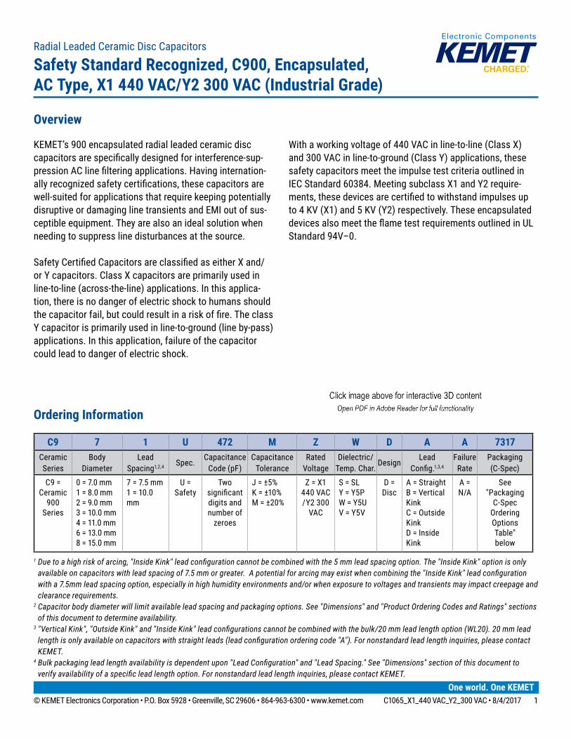
KEMET’s 900 encapsulated radial leaded ceramic disc capacitors are specifically designed for interference-sup-pression AC line filtering applications. Having internation-ally recognized safety certifications, these capacitors are well-suited for applications that require keeping potentially disruptive or damaging line transients and EMI out of sus-ceptible equipment. They are also an ideal solution when needing to suppress line disturbances at the source.
Safety Certified Capacitors are classified as either X and/or Y capacitors. Class X capacitors are primarily used in line-to-line (across-the-line) applications. In this applica-tion, there is no danger of electric shock to humans should the capacitor fail, but could result in a risk of fire. The class Y capacitor is primarily used in line-to-ground (line by-pass) applications. In this application, failure of the capacitor could lead to danger of electric shock.
With a working voltage of 440 VAC in line-to-line (Class X) and 300 VAC in line-to-ground (Class Y) applications, these safety capacitors meet the impulse test criteria outlined in IEC Standard 60384. Meeting subclass X1 and Y2 require-ments, these devices are certified to withstand impulses up to 4 KV (X1) and 5 KV (Y2) respectively. These encapsulated devices also meet the flame test requirements outlined in UL Standard 94V–0.
Radial Leaded Ceramic Disc Capacitors
Safety Standard Recognized, C900, Encapsulated, AC Type, X1 440 VAC/Y2 300 VAC (Industrial Grade)
Ordering Information
C9 7 1 U 472 M Z W D A A 7317Ceramic Series
BodyDiameter
Lead Spacing1,2,4 Spec.
Capacitance Code (pF)
Capacitance Tolerance
Rated Voltage
Dielectric/ Temp. Char.
DesignLead
Config.1,3,4
Failure Rate
Packaging (C-Spec)
C9 = Ceramic
900 Series
0 = 7.0 mm1 = 8.0 mm2 = 9.0 mm3 = 10.0 mm4 = 11.0 mm6 = 13.0 mm8 = 15.0 mm
7 = 7.5 mm1 = 10.0 mm
U = Safety
Two significant digits and number of
zeroes
J = ±5%K = ±10%M = ±20%
Z = X1 440 VAC /Y2 300
VAC
S = SL Y = Y5PW = Y5UV = Y5V
D = Disc
A = StraightB = Vertical KinkC = Outside KinkD = Inside Kink
A = N/A
See "Packaging
C-Spec Ordering Options Table" below
1 Due to a high risk of arcing, "Inside Kink" lead configuration cannot be combined with the 5 mm lead spacing option. The "Inside Kink" option is only available on capacitors with lead spacing of 7.5 mm or greater. A potential for arcing may exist when combining the "Inside Kink" lead configuration with a 7.5mm lead spacing option, especially in high humidity environments and/or when exposure to voltages and transients may impact creepage and clearance requirements.
2 Capacitor body diameter will limit available lead spacing and packaging options. See "Dimensions" and "Product Ordering Codes and Ratings" sections of this document to determine availability.
3 "Vertical Kink", "Outside Kink" and "Inside Kink" lead configurations cannot be combined with the bulk/20 mm lead length option (WL20). 20 mm lead length is only available on capacitors with straight leads (lead configuration ordering code "A"). For nonstandard lead length inquiries, please contact KEMET.
4 Bulk packaging lead length availability is dependent upon "Lead Configuration" and "Lead Spacing." See "Dimensions" section of this document to verify availability of a specific lead length option. For nonstandard lead length inquiries, please contact KEMET.
© KEMET Electronics Corporation • P.O. Box 5928 • Greenville, SC 29606 • 864-963-6300 • www.kemet.com C1065_X1_440 VAC_Y2_300 VAC • 8/4/2017 2
Radial Leaded Ceramic Disc CapacitorsSafety Standard Recognized, C900, Encapsulated, AC Type, X1 440 VAC/Y2 300 VAC (Industrial Grade)
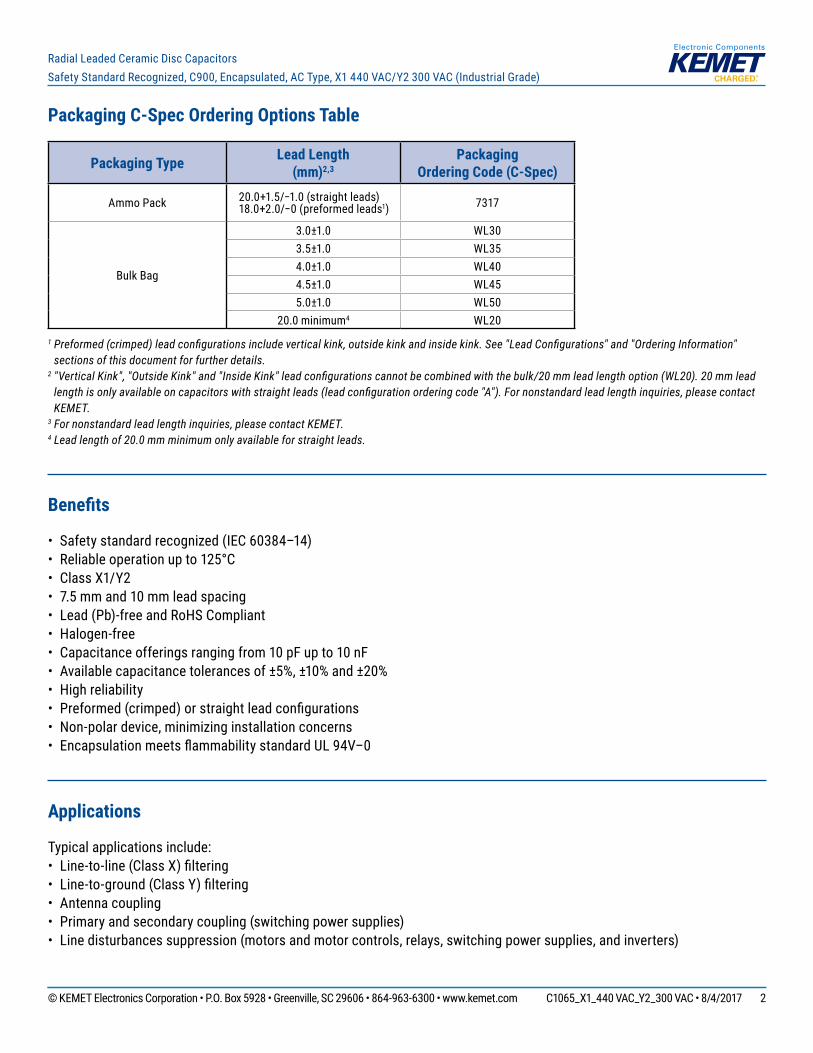
Packaging C-Spec Ordering Options Table
Packaging Type Lead Length (mm)2,3
Packaging Ordering Code (C-Spec)
Ammo Pack 20.0+1.5/−1.0 (straight leads) 18.0+2.0/−0 (preformed leads1) 7317
Bulk Bag
3.0±1.0 WL303.5±1.0 WL354.0±1.0 WL404.5±1.0 WL455.0±1.0 WL50
20.0 minimum4 WL201 Preformed (crimped) lead configurations include vertical kink, outside kink and inside kink. See "Lead Configurations" and "Ordering Information"
sections of this document for further details.2 "Vertical Kink", "Outside Kink" and "Inside Kink" lead configurations cannot be combined with the bulk/20 mm lead length option (WL20). 20 mm lead
length is only available on capacitors with straight leads (lead configuration ordering code "A"). For nonstandard lead length inquiries, please contact KEMET.
3 For nonstandard lead length inquiries, please contact KEMET.4 Lead length of 20.0 mm minimum only available for straight leads.
Benefits
• Safety standard recognized (IEC 60384–14)• Reliable operation up to 125°C• Class X1/Y2 • 7.5 mm and 10 mm lead spacing• Lead (Pb)-free and RoHS Compliant• Halogen-free• Capacitance offerings ranging from 10 pF up to 10 nF • Available capacitance tolerances of ±5%, ±10% and ±20%• High reliability• Preformed (crimped) or straight lead configurations• Non-polar device, minimizing installation concerns• Encapsulation meets flammability standard UL 94V–0
Applications
Typical applications include: • Line-to-line (Class X) filtering• Line-to-ground (Class Y) filtering• Antenna coupling• Primary and secondary coupling (switching power supplies)• Line disturbances suppression (motors and motor controls, relays, switching power supplies, and inverters)
© KEMET Electronics Corporation • P.O. Box 5928 • Greenville, SC 29606 • 864-963-6300 • www.kemet.com C1065_X1_440 VAC_Y2_300 VAC • 8/4/2017 3
Radial Leaded Ceramic Disc CapacitorsSafety Standard Recognized, C900, Encapsulated, AC Type, X1 440 VAC/Y2 300 VAC (Industrial Grade)
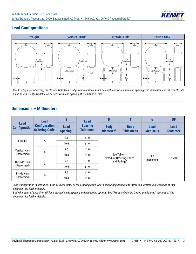
Lead Configurations
Straight Vertical Kink Outside Kink Inside Kink1
D T
LL
SF
3.0Maximum
D T
LL
SF
4.0 Maximum
3.0Maximum
D T
LL
SF
5.0 Maximum
3.0Maximum
D T
LL
SF
5.0 Maximum
3.0Maximum
1 Due to a high risk of arcing, the "Inside Kink" lead configuration option cannot be combined with 5 mm lead spacing ("S" dimension above). The "Inside Kink" option is only available on devices with lead spacing of 7.5 mm or 10 mm.
Dimensions – Millimeters
Lead Configuration
Lead Configuration
Ordering Code1
S Lead Spacing
Tolerance
D T e ØF
Lead Spacing2
Body Diameter2
Body Thickness
Lead Meniscus
Lead Diameter
Straight A7.5 ±1.0
See Table 1 - "Product Ordering Codes
and Ratings"
3.0 maximum 0.55±0.1
10.0 ±1.0
Vertical Kink (Preformed) B
7.5 ±1.0
10.0 ±1.0
Outside Kink (Preformed) C
7.5 ±1.0
10.0 ±1.0
Inside Kink (Preformed) D
7.5 ±1.0
10.0 ±1.0
1 Lead Configuration is identified in the 13th character of the ordering code. See "Lead Configuration" and "Ordering Information" sections of this document for further details.
2 Body diameter of capacitor will limit available lead spacing and packaging options. See "Product Ordering Codes and Ratings" sections of this document for further details.
© KEMET Electronics Corporation • P.O. Box 5928 • Greenville, SC 29606 • 864-963-6300 • www.kemet.com C1065_X1_440 VAC_Y2_300 VAC • 8/4/2017 4
Radial Leaded Ceramic Disc CapacitorsSafety Standard Recognized, C900, Encapsulated, AC Type, X1 440 VAC/Y2 300 VAC (Industrial Grade)
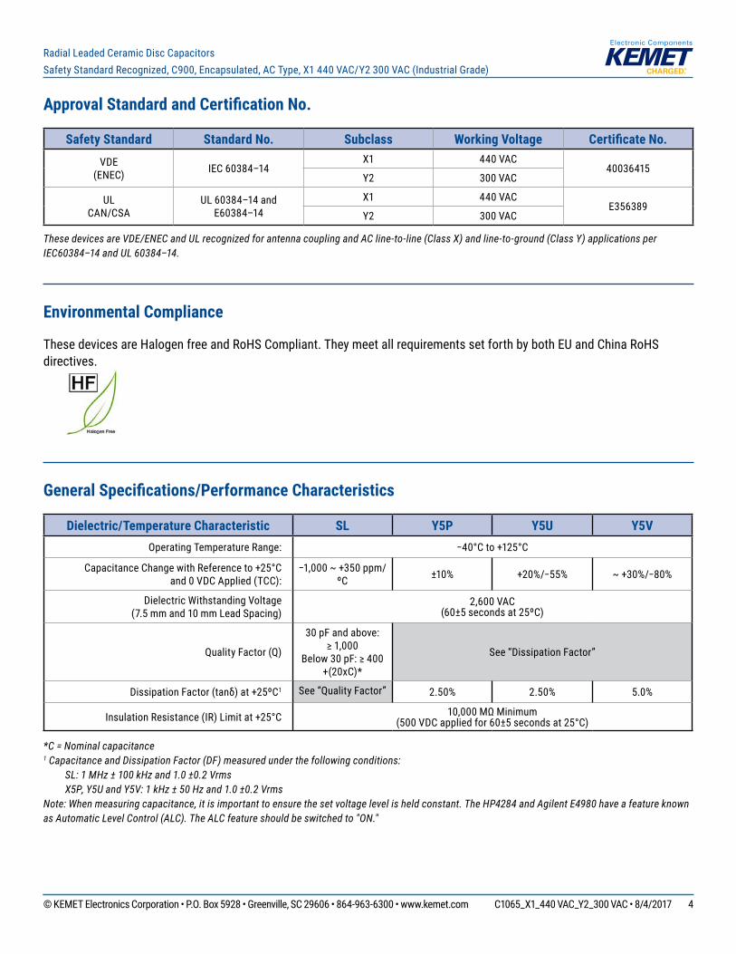
Approval Standard and Certification No.
Safety Standard Standard No. Subclass Working Voltage Certificate No.VDE
(ENEC) IEC 60384–14X1 440 VAC
40036415Y2 300 VAC
ULCAN/CSA
UL 60384–14 andE60384–14
X1 440 VACE356389
Y2 300 VAC
These devices are VDE/ENEC and UL recognized for antenna coupling and AC line-to-line (Class X) and line-to-ground (Class Y) applications per IEC60384–14 and UL 60384–14.
Environmental Compliance
These devices are Halogen free and RoHS Compliant. They meet all requirements set forth by both EU and China RoHS directives.
General Specifications/Performance Characteristics
Dielectric/Temperature Characteristic SL Y5P Y5U Y5VOperating Temperature Range: −40°C to +125°C
Capacitance Change with Reference to +25°C and 0 VDC Applied (TCC):
−1,000 ~ +350 ppm/ºC ±10% +20%/−55% ~ +30%/−80%
Dielectric Withstanding Voltage (7.5 mm and 10 mm Lead Spacing)
2,600 VAC (60±5 seconds at 25ºC)
Quality Factor (Q)
30 pF and above: ≥ 1,000
Below 30 pF: ≥ 400 +(20xC)*
See “Dissipation Factor”
Dissipation Factor (tanδ) at +25ºC1 See “Quality Factor” 2.50% 2.50% 5.0%
Insulation Resistance (IR) Limit at +25°C 10,000 MΩ Minimum (500 VDC applied for 60±5 seconds at 25°C)
*C = Nominal capacitance1 Capacitance and Dissipation Factor (DF) measured under the following conditions: SL: 1 MHz ± 100 kHz and 1.0 ±0.2 Vrms X5P, Y5U and Y5V: 1 kHz ± 50 Hz and 1.0 ±0.2 Vrms Note: When measuring capacitance, it is important to ensure the set voltage level is held constant. The HP4284 and Agilent E4980 have a feature known as Automatic Level Control (ALC). The ALC feature should be switched to "ON."
© KEMET Electronics Corporation • P.O. Box 5928 • Greenville, SC 29606 • 864-963-6300 • www.kemet.com C1065_X1_440 VAC_Y2_300 VAC • 8/4/2017 5
Radial Leaded Ceramic Disc CapacitorsSafety Standard Recognized, C900, Encapsulated, AC Type, X1 440 VAC/Y2 300 VAC (Industrial Grade)
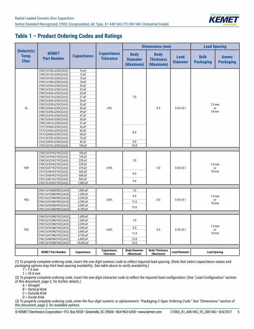
Table 1 – Product Ordering Codes and Ratings
(1) To properly complete ordering code, insert the one-digit numeric code to reflect required lead spacing: (Note that select capacitance values and packaging options may limit lead spacing availability. See table above to verify availability.) 7 = 7.5 mm 1 = 10.0 mm (2) To properly complete ordering code, insert the one-digit character code to reflect the required lead configuration: (See "Lead Configuration" section of this document, page 2, for further details.) A = Straight B = Vertical Kink C = Outside Kink D = Inside Kink(3) To properly complete ordering code, enter the four-digit numeric or alphanumeric "Packaging C-Spec Ordering Code." See "Dimensions" section of this document, page 2, for available options.
Dielectric/ Temp. Char.
KEMET Part Number Capacitance Capacitance
Tolerance
Dimensions (mm) Lead Spacing
Body Diameter
(Maximum)
Body Thickness (Maximum)
Lead Diameter
Bulk Packaging
Ammo Packaging
SL
C90(1)U100JZSD(2)A(3) 10 pF
±5%
7.0
5.0 0.55 ±0.17.5 mm
or10 mm
C90(1)U120JZSD(2)A(3) 12 pFC90(1)U150JZSD(2)A(3) 15 pFC90(1)U180JZSD(2)A(3) 18 pFC90(1)U200JZSD(2)A(3) 20 pFC90(1)U220JZSD(2)A(3) 22 pFC90(1)U240JZSD(2)A(3) 24 pFC90(1)U270JZSD(2)A(3) 27 pFC90(1)U300JZSD(2)A(3) 30 pFC90(1)U330JZSD(2)A(3) 33 pFC90(1)U360JZSD(2)A(3) 36 pFC90(1)U390JZSD(2)A(3) 39 pFC90(1)U470JZSD(2)A(3) 47 pFC90(1)U500JZSD(2)A(3) 50 pFC90(1)U510JZSD(2)A(3) 51 pFC91(1)U560JZSD(2)A(3) 56 pF
8.0C91(1)U620JZSD(2)A(3) 62 pFC91(1)U680JZSD(2)A(3) 68 pFC91(1)U750JZSD(2)A(3) 75 pFC92(1)U820JZSD(2)A(3) 82 pF 9.0C93(1)U101JZSD(2)A(3) 100 pF 10.0
Y5P
C90(1)U101KZYD(2)A(3) 100 pF
±10%
7.0
5.0 0.55 ±0.17.5 mm
or10 mm
C90(1)U151KZYD(2)A(3) 150 pFC90(1)U221KZYD(2)A(3) 220 pFC90(1)U331KZYD(2)A(3) 330 pFC90(1)U471KZYD(2)A(3) 470 pFC91(1)U561KZYD(2)A(3) 560 pF 8.0C91(1)U681KZYD(2)A(3) 680 pFC92(1)U821KZYD(2)A(3) 820 pF 9.0C92(1)U102KZYD(2)A(3) 1,000 pF
Y5U
C90(1)U102MZWD(2)A(3) 1,000 pF
±20%
7.0
5.0 0.55 ±0.17.5 mm
or10 mm
C92(1)U152MZWD(2)A(3) 1,500 pF 9.0C92(1)U222MZWD(2)A(3) 2,200 pFC94(1)U332MZWD(2)A(3) 3,300 pF 11.0C96(1)U392MZWD(2)A(3) 3,900 pF 13.0C96(1)U472MZWD(2)A(3) 4,700 pF
Y5V
C90(1)U102MZVD(2)A(3) 1,000 pF
±20%
7.0
5.0 0.55 ±0.17.5 mm
or10 mm
C90(1)U152MZVD(2)A(3) 1,500 pFC90(1)U222MZVD(2)A(3) 2,200 pFC92(1)U332MZVD(2)A(3) 3,300 pF 9.0C94(1)U392MZVD(2)A(3) 3,900 pF 11.0C94(1)U472MZVD(2)A(3) 4,700 pFC96(1)U682MZVD(2)A(3) 6,800 pF 13.0C98(1)U103MZVD(2)A(3) 10,000 pF 15.0
KEMET Part Number Capacitance Capacitance Tolerance
Body Diameter (Maximum)
Body Thickness (Maximum) Lead Diameter Lead Spacing

© KEMET Electronics Corporation • P.O. Box 5928 • Greenville, SC 29606 • 864-963-6300 • www.kemet.com C1065_X1_440 VAC_Y2_300 VAC • 8/4/2017 6
Radial Leaded Ceramic Disc CapacitorsSafety Standard Recognized, C900, Encapsulated, AC Type, X1 440 VAC/Y2 300 VAC (Industrial Grade)
Table 2 – Performance & Reliability: Test Methods and Conditions
Item Specification Test MethodOperating Temperature Range −40ºC to +125ºC
Dielectric Strength
Between lead wires No failures The capacitor shall not be damaged when 2,600 VAC(rms) is
applied between the lead wires for 60 seconds.
Body Insulation No failures
The terminals (leads) of the capacitor shall be connected together. A metal foil is tightly wrapped around the body of the capacitor at a distance of about 3 to 4 mm from each terminal. The capacitor is then inserted into a container filled with metal balls approximately 1 mm in diameter. 2,600 VAC(rms) is applied for 60 seconds between the capacitor lead wires and metal balls.
MetalFoil
MetalBalls
about3 to 4 mm
Insulation Resistance (IR) 10,000 MΩ minimum The insulation resistance shall be measured with 500±50 VDC applied after 60±5 seconds of charging.
Capacitance Within specified tolerance
Y5P, Y5U and Y5V: Capacitance is measured at 1 kHz ±20% and 5 Vrms or less. (20±2°C) SL: Capacitance is measured at 1 MHz ±20% and 1.0±0.2 Vrms (25°C)Dissipation Factor (DF) or Q
Temperature Characteristics Specification
Y5P, Y5U DF ≤ 2.5%
Y5V DF ≤ 5.0%
SL ≥ 30 pF: Q ≥ 1000< 30 pF: Q ≥ 400
+(20 x C)C = Nominal capacitance
Temperature Characteristics
Temperature Characteristics
Capacitance Change
Y5P Within ±10%
Y5U Within +20%/−55%
Y5V Within ~+30%/−80%
SL −1,000 ~+350 ppmºC
(+20ºC ~+85ºC)
A capacitance measurement is made at each step specified:
Step Temperature1 +20±2ºC
2 −25±2ºC
3 +20±2ºC
4 +85±2ºC
5 +20±2ºC
Pre-treatment: Capacitor is stored at 85±2ºC for 1 hour and then placed at room condition1 for 24±2 hours before measurement.
Terminal Strength
Tensile Lead wire or capacitor body shall not break.
With the termination in its normal position, the specimen is held by its body in such a manner that the axis of the termination is vertical; a tensile force of 10 N is applied to the termination in the direction of its axis and acting in a direction away from the body of the specimen.
Bending Lead wire or capacitor body shall not break.
With the termination in its normal position, the specimen is held by its body in such a manner that the axis of the termination is vertical; a mass force of 5 N is then suspended from the end of the termination. The body of the specimen is then inclined within a period of 2 to 3 seconds, through an angle of approximately 90° in the vertical plane and then resumed to its initial position over the same period of time; this operation constitutes one bend. One bend immediately followed by a second bend in the opposite direction.
1 “Room Condition” is defined as follows: Temperature: 15 ~ 35°C/Humidity: 45 ~ 75%/Atmospheric Pressure: 86 ~ 106 kPa.
© KEMET Electronics Corporation • P.O. Box 5928 • Greenville, SC 29606 • 864-963-6300 • www.kemet.com C1065_X1_440 VAC_Y2_300 VAC • 8/4/2017 7
Radial Leaded Ceramic Disc CapacitorsSafety Standard Recognized, C900, Encapsulated, AC Type, X1 440 VAC/Y2 300 VAC (Industrial Grade)
Table 2 – Performance & Reliability: Test Methods and Conditions cont'd
Item Specification Test Method
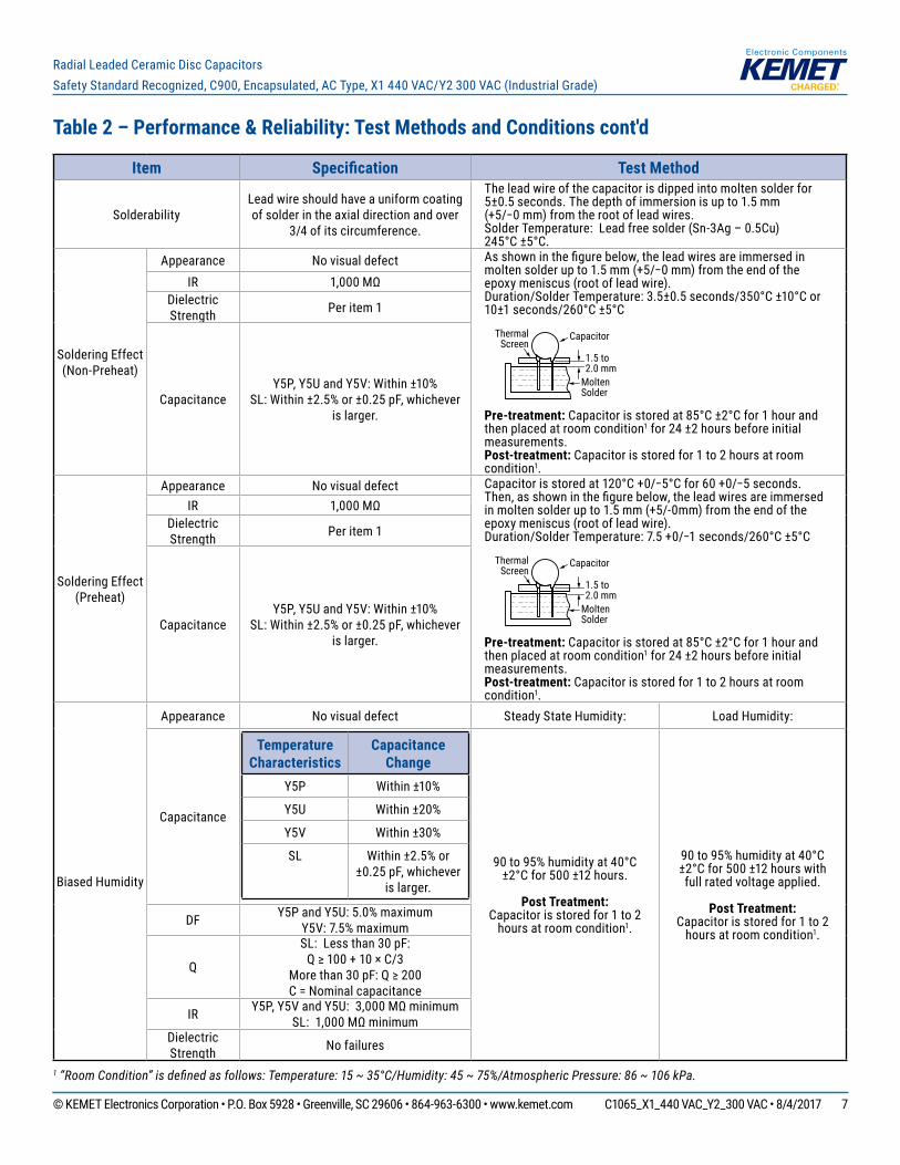
SolderabilityLead wire should have a uniform coating of solder in the axial direction and over
3/4 of its circumference.
The lead wire of the capacitor is dipped into molten solder for 5±0.5 seconds. The depth of immersion is up to 1.5 mm (+5/−0 mm) from the root of lead wires. Solder Temperature: Lead free solder (Sn-3Ag – 0.5Cu) 245°C ±5°C.
Soldering Effect (Non-Preheat)
Appearance No visual defect As shown in the figure below, the lead wires are immersed in molten solder up to 1.5 mm (+5/−0 mm) from the end of the epoxy meniscus (root of lead wire). Duration/Solder Temperature: 3.5±0.5 seconds/350°C ±10°C or 10±1 seconds/260°C ±5°C
MoltenSolder
1.5 to2.0 mm
CapacitorThermalScreen
Pre-treatment: Capacitor is stored at 85°C ±2°C for 1 hour and then placed at room condition1 for 24 ±2 hours before initial measurements. Post-treatment: Capacitor is stored for 1 to 2 hours at room condition1.
IR 1,000 MΩDielectric Strength Per item 1
CapacitanceY5P, Y5U and Y5V: Within ±10%
SL: Within ±2.5% or ±0.25 pF, whichever is larger.
Soldering Effect (Preheat)
Appearance No visual defect Capacitor is stored at 120°C +0/−5°C for 60 +0/−5 seconds. Then, as shown in the figure below, the lead wires are immersed in molten solder up to 1.5 mm (+5/-0mm) from the end of the epoxy meniscus (root of lead wire). Duration/Solder Temperature: 7.5 +0/−1 seconds/260°C ±5°C
MoltenSolder
1.5 to2.0 mm
CapacitorThermalScreen
Pre-treatment: Capacitor is stored at 85°C ±2°C for 1 hour and then placed at room condition1 for 24 ±2 hours before initial measurements. Post-treatment: Capacitor is stored for 1 to 2 hours at room condition1.
IR 1,000 MΩDielectric Strength Per item 1
CapacitanceY5P, Y5U and Y5V: Within ±10%
SL: Within ±2.5% or ±0.25 pF, whichever is larger.
Biased Humidity
Appearance No visual defect Steady State Humidity: Load Humidity:
Capacitance
Temperature Characteristics
Capacitance Change
Y5P Within ±10%
Y5U Within ±20%
Y5V Within ±30%
SL Within ±2.5% or ±0.25 pF, whichever
is larger.
90 to 95% humidity at 40°C ±2°C for 500 ±12 hours.
Post Treatment:
Capacitor is stored for 1 to 2 hours at room condition1.
90 to 95% humidity at 40°C ±2°C for 500 ±12 hours with full rated voltage applied.
Post Treatment:
Capacitor is stored for 1 to 2 hours at room condition1.
DF Y5P and Y5U: 5.0% maximum Y5V: 7.5% maximum
Q
SL: Less than 30 pF: Q ≥ 100 + 10 × C/3
More than 30 pF: Q ≥ 200C = Nominal capacitance
IR Y5P, Y5V and Y5U: 3,000 MΩ minimum SL: 1,000 MΩ minimum
Dielectric Strength No failures
1 “Room Condition” is defined as follows: Temperature: 15 ~ 35°C/Humidity: 45 ~ 75%/Atmospheric Pressure: 86 ~ 106 kPa.
© KEMET Electronics Corporation • P.O. Box 5928 • Greenville, SC 29606 • 864-963-6300 • www.kemet.com C1065_X1_440 VAC_Y2_300 VAC • 8/4/2017 8
Radial Leaded Ceramic Disc CapacitorsSafety Standard Recognized, C900, Encapsulated, AC Type, X1 440 VAC/Y2 300 VAC (Industrial Grade)
Table 2 – Performance & Reliability: Test Methods and Conditions cont'd
Item Specification Test Method
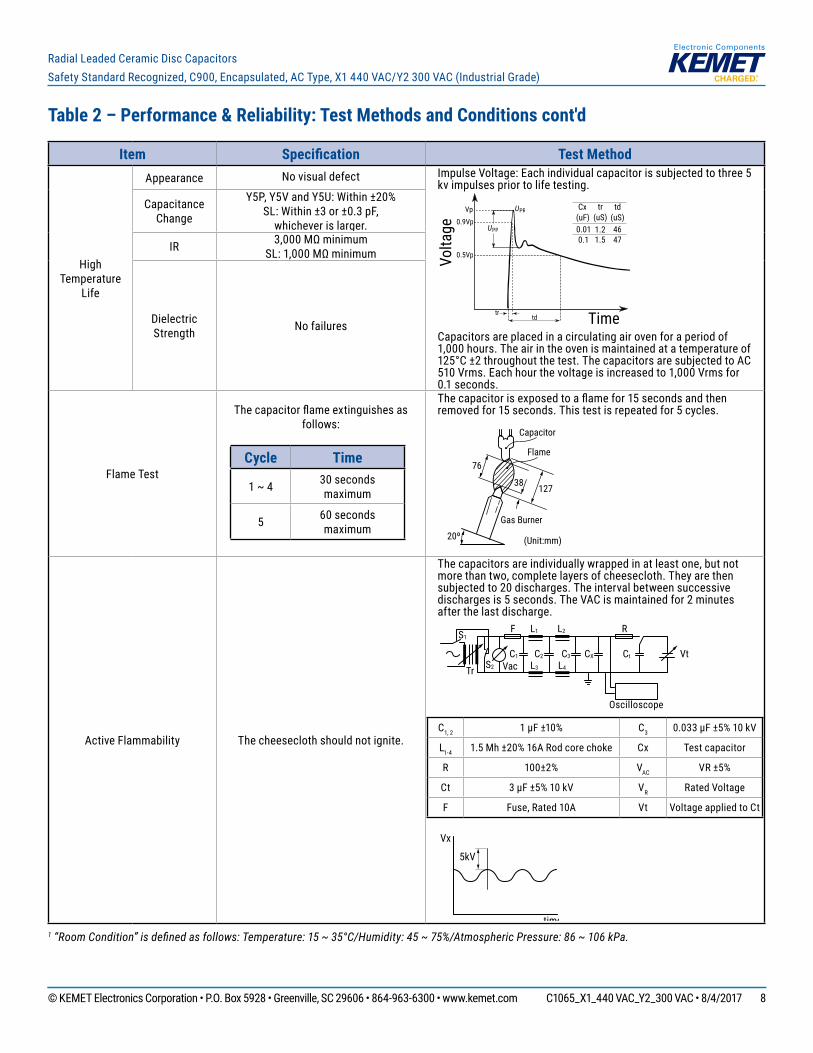
High Temperature
Life
Appearance No visual defect Impulse Voltage: Each individual capacitor is subjected to three 5 kv impulses prior to life testing.
PPU
PRUVp
0.9Vp
0.5VpVolta
ge
trtd Time
td(uS)4647
tr(uS)1.21.5
Cx(uF)0.010.1
Capacitors are placed in a circulating air oven for a period of 1,000 hours. The air in the oven is maintained at a temperature of 125°C ±2 throughout the test. The capacitors are subjected to AC 510 Vrms. Each hour the voltage is increased to 1,000 Vrms for 0.1 seconds.
Capacitance Change
Y5P, Y5V and Y5U: Within ±20% SL: Within ±3 or ±0.3 pF,
whichever is larger.
IR 3,000 MΩ minimum SL: 1,000 MΩ minimum
Dielectric Strength No failures
Flame Test
The capacitor flame extinguishes as follows:
Cycle Time
1 ~ 4 30 seconds maximum
5 60 seconds maximum
The capacitor is exposed to a flame for 15 seconds and then removed for 15 seconds. This test is repeated for 5 cycles.
76
Capacitor
Flame
38 127
20º
Gas Burner
(Unit:mm)
Active Flammability The cheesecloth should not ignite.
The capacitors are individually wrapped in at least one, but not more than two, complete layers of cheesecloth. They are then subjected to 20 discharges. The interval between successive discharges is 5 seconds. The VAC is maintained for 2 minutes after the last discharge.
S1
Tr VacS2
C1
L3 L4
C2 C3 CX Ct Vt
L1F R
Oscilloscope
L2
C1, 2 1 μF ±10% C3 0.033 μF ±5% 10 kV
L1-4 1.5 Mh ±20% 16A Rod core choke Cx Test capacitor
R 100±2% VAC VR ±5%
Ct 3 μF ±5% 10 kV VR Rated Voltage
F Fuse, Rated 10A Vt Voltage applied to Ct
Vx
5kV
time1 “Room Condition” is defined as follows: Temperature: 15 ~ 35°C/Humidity: 45 ~ 75%/Atmospheric Pressure: 86 ~ 106 kPa.
© KEMET Electronics Corporation • P.O. Box 5928 • Greenville, SC 29606 • 864-963-6300 • www.kemet.com C1065_X1_440 VAC_Y2_300 VAC • 8/4/2017 9
Radial Leaded Ceramic Disc CapacitorsSafety Standard Recognized, C900, Encapsulated, AC Type, X1 440 VAC/Y2 300 VAC (Industrial Grade)
Table 2 – Performance & Reliability: Test Methods and Conditions cont'd
Item Specification Test Method
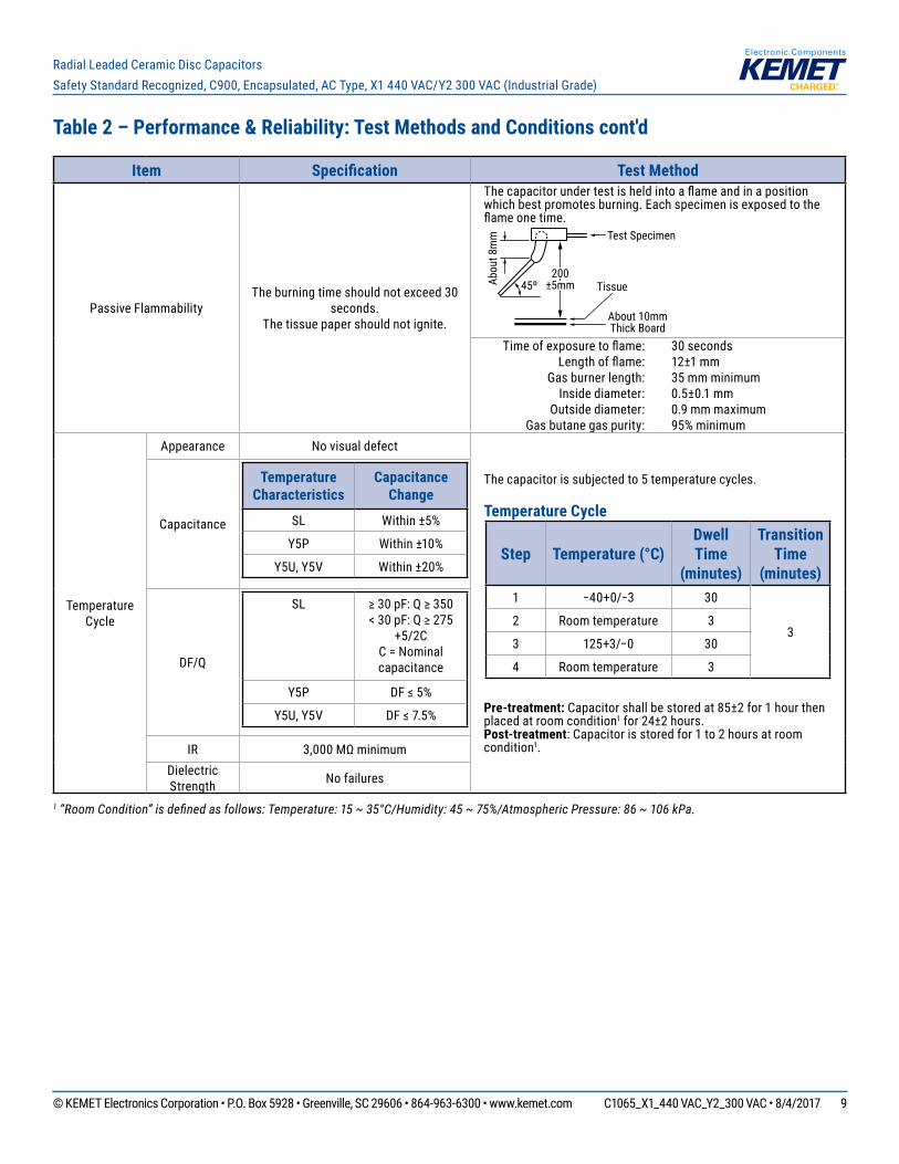
Passive FlammabilityThe burning time should not exceed 30
seconds. The tissue paper should not ignite.
The capacitor under test is held into a flame and in a position which best promotes burning. Each specimen is exposed to the flame one time.
200±5mmAb
out 8
mm
45º
Test Specimen
About 10mmThick Board
Tissue
Time of exposure to flame:Length of flame:
Gas burner length:Inside diameter:
Outside diameter:Gas butane gas purity:
30 seconds12±1 mm 35 mm minimum0.5±0.1 mm 0.9 mm maximum 95% minimum
Temperature Cycle
Appearance No visual defect
The capacitor is subjected to 5 temperature cycles.
Temperature Cycle
Step Temperature (°C)Dwell Time
(minutes)
Transition Time
(minutes)1 −40+0/−3 30
32 Room temperature 3
3 125+3/−0 30
4 Room temperature 3
Pre-treatment: Capacitor shall be stored at 85±2 for 1 hour then placed at room condition1 for 24±2 hours. Post-treatment: Capacitor is stored for 1 to 2 hours at room condition1.
Capacitance
Temperature Characteristics
Capacitance Change
SL Within ±5%
Y5P Within ±10%
Y5U, Y5V Within ±20%
DF/Q
SL ≥ 30 pF: Q ≥ 350< 30 pF: Q ≥ 275
+5/2CC = Nominal capacitance
Y5P DF ≤ 5%
Y5U, Y5V DF ≤ 7.5%
IR 3,000 MΩ minimumDielectric Strength No failures
1 “Room Condition” is defined as follows: Temperature: 15 ~ 35°C/Humidity: 45 ~ 75%/Atmospheric Pressure: 86 ~ 106 kPa.
© KEMET Electronics Corporation • P.O. Box 5928 • Greenville, SC 29606 • 864-963-6300 • www.kemet.com C1065_X1_440 VAC_Y2_300 VAC • 8/4/2017 10
Radial Leaded Ceramic Disc CapacitorsSafety Standard Recognized, C900, Encapsulated, AC Type, X1 440 VAC/Y2 300 VAC (Industrial Grade)
Soldering and Mounting Information
Soldering:When soldering this product to a PCB/PWB, do not exceed the solder heat resistance specification of the capacitor. Subjecting this product to excessive heating could reflow the solder joint between the lead and ceramic element and/or may result in thermal shocks that can crack the ceramic element.
When soldering these capacitors with a soldering iron, it should be performed under the following conditions: • Temperature of iron-tip: 400ºC maximum • Soldering iron wattage: 50 W maximum • Soldering time: 3.5 seconds maximum Cleaning (ultrasonic cleaning): To perform ultrasonic cleaning, observe the following conditions: • Rinse bath capacity: Output of 20 watts per liter or less• Rinsing time: 5 minute maximum• Do not vibrate the PCB/PWB directly • Excessive ultrasonic cleaning may lead to fatigue destruction of the lead wires
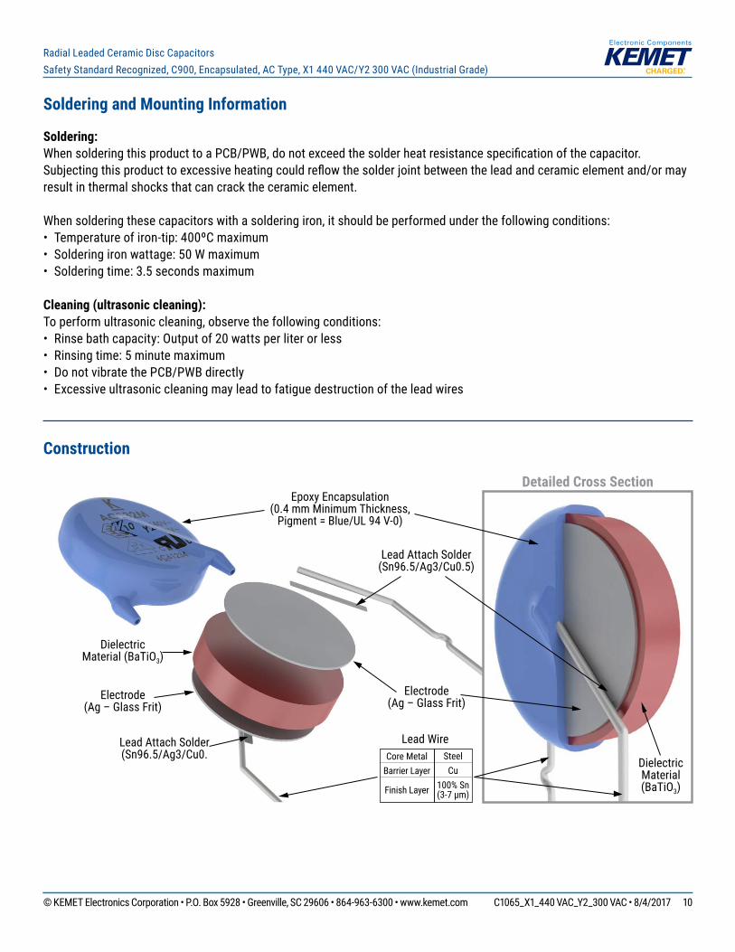
Construction
Detailed Cross SectionEpoxy Encapsulation
(0.4 mm Minimum Thickness, Pigment = Blue/UL 94 V-0)
Lead Attach Solder(Sn96.5/Ag3/Cu0.5)
Electrode(Ag – Glass Frit)
Core MetalBarrier Layer
Finish Layer
SteelCu
100% Sn(3-7 µm)
Lead Wire
Dielectric Material (BaTiO3)
Lead Attach Solder(Sn96.5/Ag3/Cu0.
Electrode(Ag – Glass Frit)
Dielectric Material(BaTiO3)
© KEMET Electronics Corporation • P.O. Box 5928 • Greenville, SC 29606 • 864-963-6300 • www.kemet.com C1065_X1_440 VAC_Y2_300 VAC • 8/4/2017 11
Radial Leaded Ceramic Disc CapacitorsSafety Standard Recognized, C900, Encapsulated, AC Type, X1 440 VAC/Y2 300 VAC (Industrial Grade)
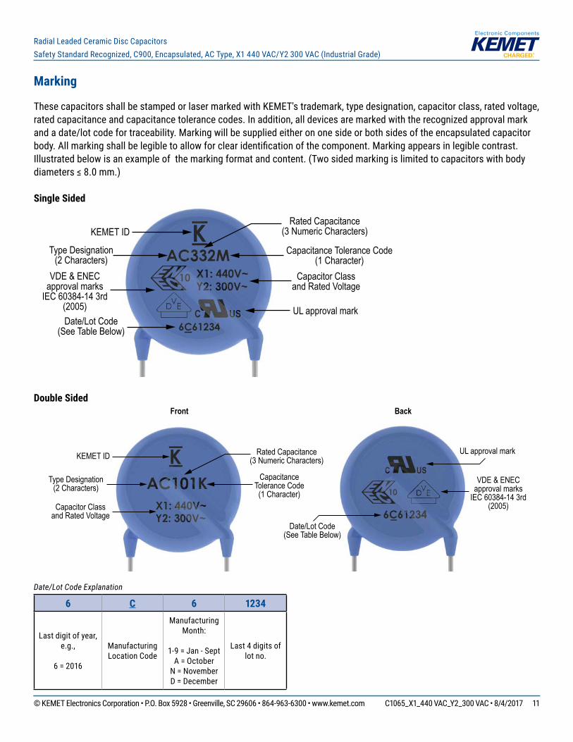
Marking
These capacitors shall be stamped or laser marked with KEMET's trademark, type designation, capacitor class, rated voltage, rated capacitance and capacitance tolerance codes. In addition, all devices are marked with the recognized approval mark and a date/lot code for traceability. Marking will be supplied either on one side or both sides of the encapsulated capacitor body. All marking shall be legible to allow for clear identification of the component. Marking appears in legible contrast. Illustrated below is an example of the marking format and content. (Two sided marking is limited to capacitors with body diameters ≤ 8.0 mm.)
Single Sided
UL approval mark
VDE & ENECapproval marks
IEC 60384-14 3rd(2005)
Rated Capacitance(3 Numeric Characters)
Capacitance Tolerance Code(1 Character)
Capacitor Classand Rated Voltage
KEMET ID
Type Designation(2 Characters)
Date/Lot Code(See Table Below)
Double Sided
Capacitor Classand Rated Voltage
Front Back
KEMET ID
Type Designation(2 Characters)
VDE & ENECapproval marks
IEC 60384-14 3rd(2005)
UL approval mark
Date/Lot Code(See Table Below)
Rated Capacitance(3 Numeric Characters)
CapacitanceTolerance Code
(1 Character)
Date/Lot Code Explanation
6 C 6 1234
Last digit of year, e.g.,
6 = 2016
Manufacturing Location Code
Manufacturing Month:
1-9 = Jan - Sept
A = October N = November D = December
Last 4 digits of lot no.
© KEMET Electronics Corporation • P.O. Box 5928 • Greenville, SC 29606 • 864-963-6300 • www.kemet.com C1065_X1_440 VAC_Y2_300 VAC • 8/4/2017 12
Radial Leaded Ceramic Disc CapacitorsSafety Standard Recognized, C900, Encapsulated, AC Type, X1 440 VAC/Y2 300 VAC (Industrial Grade)
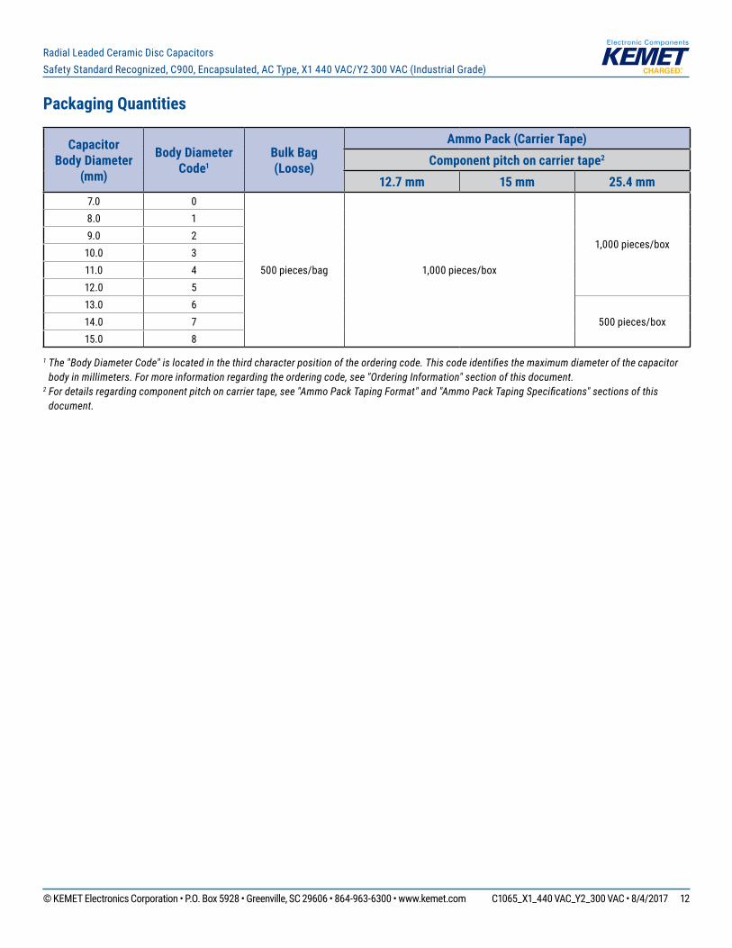
Packaging Quantities
CapacitorBody Diameter
(mm)
Body Diameter Code1
Bulk Bag(Loose)
Ammo Pack (Carrier Tape)Component pitch on carrier tape2
12.7 mm 15 mm 25.4 mm7.0 0
500 pieces/bag 1,000 pieces/box
1,000 pieces/box
8.0 19.0 2
10.0 311.0 412.0 513.0 6
500 pieces/box14.0 715.0 8
1 The "Body Diameter Code" is located in the third character position of the ordering code. This code identifies the maximum diameter of the capacitor body in millimeters. For more information regarding the ordering code, see "Ordering Information" section of this document.
2 For details regarding component pitch on carrier tape, see "Ammo Pack Taping Format" and "Ammo Pack Taping Specifications" sections of this document.
© KEMET Electronics Corporation • P.O. Box 5928 • Greenville, SC 29606 • 864-963-6300 • www.kemet.com C1065_X1_440 VAC_Y2_300 VAC • 8/4/2017 13
Radial Leaded Ceramic Disc CapacitorsSafety Standard Recognized, C900, Encapsulated, AC Type, X1 440 VAC/Y2 300 VAC (Industrial Grade)
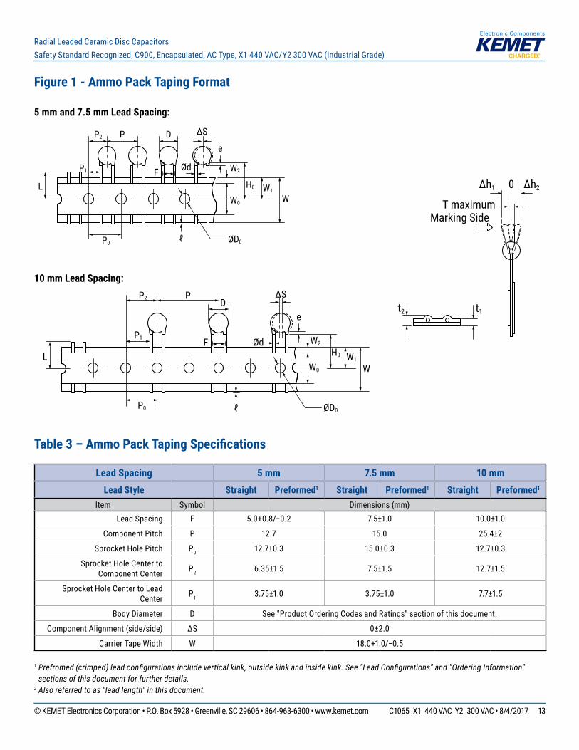
Figure 1 - Ammo Pack Taping Format
5 mm and 7.5 mm Lead Spacing:
L
P1
P2 P
F
eD
P0
W0
W2
H0 W1
W
ØD0
Ød
∆S
ℓ
10 mm Lead Spacing:
L
P1
P2 P
F
eD
P0
W0
W2
H0 W1
W
ØD0
Ød
∆S
ℓ
Table 3 – Ammo Pack Taping Specifications
1 Prefromed (crimped) lead configurations include vertical kink, outside kink and inside kink. See "Lead Configurations" and "Ordering Information" sections of this document for further details.
2 Also referred to as "lead length" in this document.
Lead Spacing 5 mm 7.5 mm 10 mmLead Style Straight Preformed1 Straight Preformed1 Straight Preformed1
Item Symbol Dimensions (mm)Lead Spacing F 5.0+0.8/−0.2 7.5±1.0 10.0±1.0
Component Pitch P 12.7 15.0 25.4±2
Sprocket Hole Pitch P0 12.7±0.3 15.0±0.3 12.7±0.3
Sprocket Hole Center to Component Center P2 6.35±1.5 7.5±1.5 12.7±1.5
Sprocket Hole Center to Lead Center P1 3.75±1.0 3.75±1.0 7.7±1.5
Body Diameter D See "Product Ordering Codes and Ratings" section of this document.
Component Alignment (side/side) ∆S 0±2.0
Carrier Tape Width W 18.0+1.0/−0.5
0
T maximumMarking Side
∆h1 ∆h2
t2 t1
© KEMET Electronics Corporation • P.O. Box 5928 • Greenville, SC 29606 • 864-963-6300 • www.kemet.com C1065_X1_440 VAC_Y2_300 VAC • 8/4/2017 14
Radial Leaded Ceramic Disc CapacitorsSafety Standard Recognized, C900, Encapsulated, AC Type, X1 440 VAC/Y2 300 VAC (Industrial Grade)
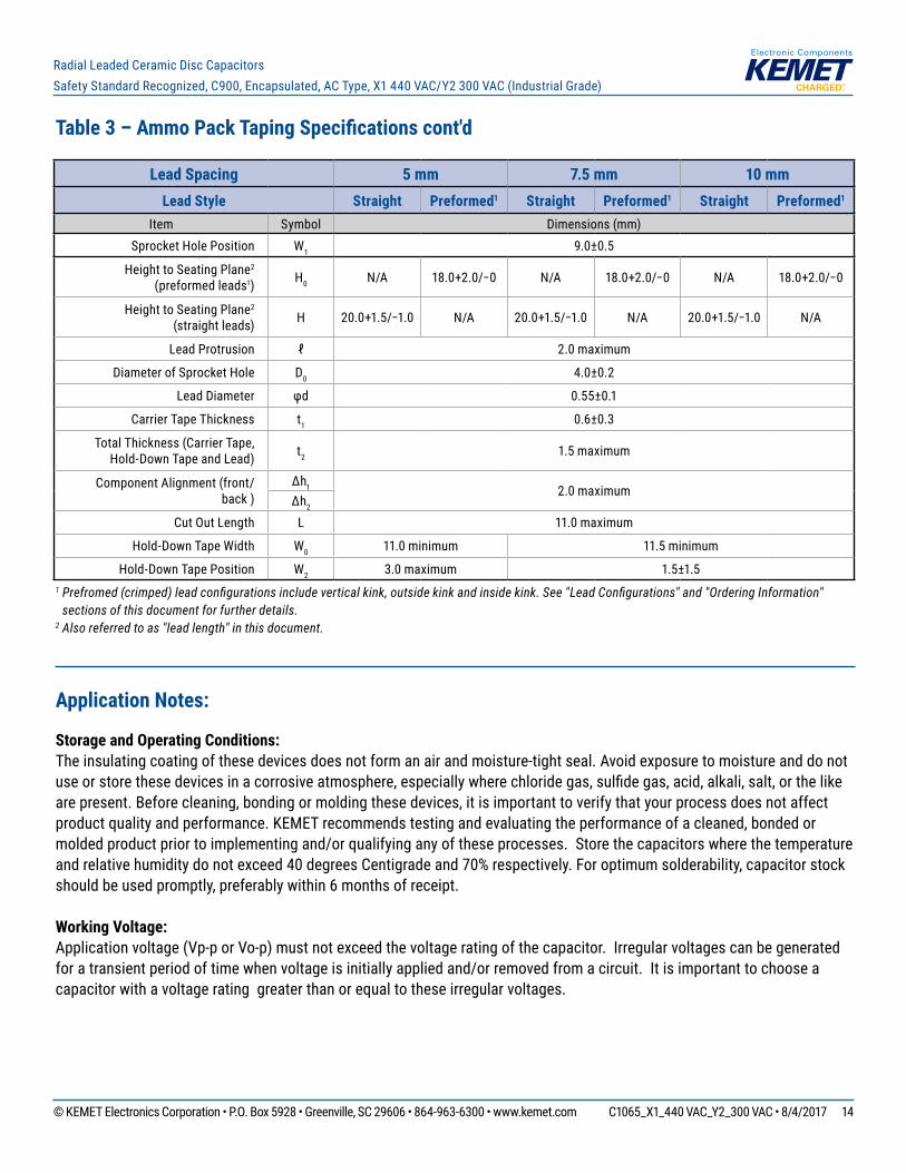
Table 3 – Ammo Pack Taping Specifications cont'd
1 Prefromed (crimped) lead configurations include vertical kink, outside kink and inside kink. See "Lead Configurations" and "Ordering Information" sections of this document for further details.
2 Also referred to as "lead length" in this document.
Application Notes:
Storage and Operating Conditions: The insulating coating of these devices does not form an air and moisture-tight seal. Avoid exposure to moisture and do not use or store these devices in a corrosive atmosphere, especially where chloride gas, sulfide gas, acid, alkali, salt, or the like are present. Before cleaning, bonding or molding these devices, it is important to verify that your process does not affect product quality and performance. KEMET recommends testing and evaluating the performance of a cleaned, bonded or molded product prior to implementing and/or qualifying any of these processes. Store the capacitors where the temperature and relative humidity do not exceed 40 degrees Centigrade and 70% respectively. For optimum solderability, capacitor stock should be used promptly, preferably within 6 months of receipt.
Working Voltage:Application voltage (Vp-p or Vo-p) must not exceed the voltage rating of the capacitor. Irregular voltages can be generated for a transient period of time when voltage is initially applied and/or removed from a circuit. It is important to choose a capacitor with a voltage rating greater than or equal to these irregular voltages.
Lead Spacing 5 mm 7.5 mm 10 mmLead Style Straight Preformed1 Straight Preformed1 Straight Preformed1
Item Symbol Dimensions (mm)Sprocket Hole Position W1 9.0±0.5
Height to Seating Plane2 (preformed leads1) H0 N/A 18.0+2.0/−0 N/A 18.0+2.0/−0 N/A 18.0+2.0/−0
Height to Seating Plane2 (straight leads) H 20.0+1.5/−1.0 N/A 20.0+1.5/−1.0 N/A 20.0+1.5/−1.0 N/A
Lead Protrusion ℓ 2.0 maximum
Diameter of Sprocket Hole D0 4.0±0.2
Lead Diameter φd 0.55±0.1
Carrier Tape Thickness t1 0.6±0.3
Total Thickness (Carrier Tape, Hold-Down Tape and Lead) t2 1.5 maximum
Component Alignment (front/back )
∆h1 2.0 maximum∆h2
Cut Out Length L 11.0 maximum
Hold-Down Tape Width W0 11.0 minimum 11.5 minimum
Hold-Down Tape Position W2 3.0 maximum 1.5±1.5

© KEMET Electronics Corporation • P.O. Box 5928 • Greenville, SC 29606 • 864-963-6300 • www.kemet.com C1065_X1_440 VAC_Y2_300 VAC • 8/4/2017 15
Radial Leaded Ceramic Disc CapacitorsSafety Standard Recognized, C900, Encapsulated, AC Type, X1 440 VAC/Y2 300 VAC (Industrial Grade)
Operating Temperature and Self-Generating Heat:The surface temperature of a capacitor should be kept below the upper limit of its rated operating temperature range. Be sure to take into account the heat generated by the capacitor itself. When the capacitor is used in a high-frequency current, pulse current or similar current, it may self-generate heat due to dielectric loss. Temperature rise due to self-generated heating should not exceed 20°C (while operated at an atmosphere temperature of 25°C).
Handling - Vibration and Impact:Do not expose these devices or their leads to excessive shock or vibration during use.
FAILURE TO FOLLOW THE ABOVE CAUTIONS MAY RESULT, WORST CASE, IN A SHORT CIRCUIT AND CAUSE FUMING OR PARTIAL DISPERSION WHEN THE PRODUCT IS USED.
© KEMET Electronics Corporation • P.O. Box 5928 • Greenville, SC 29606 • 864-963-6300 • www.kemet.com C1065_X1_440 VAC_Y2_300 VAC • 8/4/2017 16
Radial Leaded Ceramic Disc CapacitorsSafety Standard Recognized, C900, Encapsulated, AC Type, X1 440 VAC/Y2 300 VAC (Industrial Grade)
KEMET Electronics Corporation Sales Offi ces
For a complete list of our global sales offi ces, please visit www.kemet.com/sales.
DisclaimerAll product specifi cations, statements, information and data (collectively, the “Information”) in this datasheet are subject to change. The customer is responsible for checking and verifying the extent to which the Information contained in this publication is applicable to an order at the time the order is placed.
All Information given herein is believed to be accurate and reliable, but it is presented without guarantee, warranty, or responsibility of any kind, expressed or implied.
Statements of suitability for certain applications are based on KEMET Electronics Corporation’s (“KEMET”) knowledge of typical operating conditions for such applications, but are not intended to constitute – and KEMET specifi cally disclaims – any warranty concerning suitability for a specifi c customer application or use. The Information is intended for use only by customers who have the requisite experience and capability to determine the correct products for their application. Any technical advice inferred from this Information or otherwise provided by KEMET with reference to the use of KEMET’s products is given gratis, and KEMET assumes no obligation or liability for the advice given or results obtained.
Although KEMET designs and manufactures its products to the most stringent quality and safety standards, given the current state of the art, isolated component failures may still occur. Accordingly, customer applications which require a high degree of reliability or safety should employ suitable designs or other safeguards (such as installation of protective circuitry or redundancies) in order to ensure that the failure of an electrical component does not result in a risk of personal injury or property damage.
Although all product–related warnings, cautions and notes must be observed, the customer should not assume that all safety measures are indicated or that other measures may not be required.
KEMET is a registered trademark of KEMET Electronics Corporation.