safety lighting since 1953 xindex - amazon...
TRANSCRIPT

INDEX 2
NEW PRODUCTS FOR 2009 3
ANTI-COLLISION LIGHTING SYSTEM 4
POWER SUPPLIES 5-7
LIGHTHEADS 8-15
SELF-CONTAINED LIGHT ASSEMBLIES 16-22
POSITION LIGHT ASSEMBLIES 23-25
INTERIOR LIGHTING 26-29
EXTERIOR LIGHTING 30-35
MISCELLANEOUS 36
HELICOPTER SIRENS & SPEAKERS 37
NEW LIGHTING APPLICATIONS 38-40
STROBE POWER SUPPLY REPLACEMENT LISTING 41
STROBE SYSTEM RECOMMENDATIONS 42-47
WHELEN CROSS REFERENCE LIST 48-50
22
IND
EX
IND
EX
ENGINEERING COMPANY, INC.
Makers of Aviation, Automotive and Industrial Safety Lighting since 1953
The Finest Designed...Assembled...Tested...Aviation Warning Products...Manufactured In the U.S.A.
Visit Whelen at... www.whelen.comview our products & contact us! We can be e-mailed at [email protected]
Corporate Manufacturing Facilities in Chester, CT and Charlestown, NH
Office: Bob, Sharon, Carl, Jeff, Jessica, Greg
Corporate Pilots: Dennis & Jim

NE
WN
EW
AV
IAT
ION
PR
OD
UC
TS
FO
R 2
00
9 A
VIA
TIO
N P
RO
DU
CT
S F
OR
20
09
Model 71080 SeriesClass I helicopter beacon (red only), can now replace Model 70905 beacon, now available with new style mounts and electrical connections (28 &14 VDC). EC style coming soon. See page 17.
Model 70985 SeriesAn internal LED illumination product, some variations not shown (28 VDC only). See page 28.
Model 90541 SeriesSelf-contained aft POS/ACL with Diagnostix™ and redundant patent technology (28 VDC only). See page 8.
Model 71154 SeriesInternal lighting typically for the cockpit, replaces Grimes 22020 (S76 & GIV) (28 VDC only). See page 28.
Model 71170 SeriesAll LED forward POS/ACL with integrated ground recognition feature (28 VDC only). Ref. 71234. See page 10.
Model 71186 SeriesUniversal LED illumination in a very small package, under 2” behind the lens retainer (28 VDC only). See page 34.
Model 71230 SeriesLuminator 5200 Series LED solution for retrofit or new installation. Internal light swivels (28 VDC only). See Page 35.
Model 71245 SeriesSingle control, internal LED landing light (28 VDC only).See page 33.
Model 71246 SeriesSingle control, internal LED taxi or recognition light. Mounting orientation 90 degrees to Model 71125 with increased power(28 VDC only). See page 32.
Model 90433 SeriesSingle control, 6 inch round internal, LED landing light(28 VDC only). See page 30.
Model 71259 SeriesDual (independent) control, LED illumination, landing, taxi & recognition light (28 VDC only). See page 33.
Model 90520 SeriesSplit LED red/white beacon, fixed wing or helicopter with multiple mounting solutions (14 & 28 VDC).See page 16.
Model 90482 SeriesAft POS/ACL with integrated ground recognition feature. Upgrade in size and features to Model 90354, 2008 catalog. Also reference Model 71234 (28 VDC only). See page 11.
Model 90544 Series Wing tip POS/ACL with integrated redundant technology and on-boardDiagnostix, (28 VDC only). See page 8.
Model 90485 SeriesIndependent control LED taxi & recognition lighting, focused segment and spreader segment as standard (28 VDC only). See page 32.
Model 90475 SeriesFlush mounted, exterior, all LED, forward and aft POS/ACL, the smallest wing tip model Whelen manufactures. Also ref. Model 71234 (14 & 28 VDC). See page 8.
Model 71265 SeriesReplaces the Whelen halogen light array currently in production with AgustaWestland A109 and its brighter! (28 VDC only). See page 33.
Model 71325 SeriesLED exterior recognition light, replaces Whelen 71092 Series (2008 catalog and previous) at nearly three times the intensity. See page 34.
Model 90406 SeriesDeveloped for the S76 as recognition lighting, this package has migrated to other fixed wing and helicopter designs (28 VDC only). See page 33.
33
®

®
AN
TI-
CO
LL
ISIO
N L
IGH
TIN
G S
YS
TE
MA
NT
I-C
OL
LIS
ION
LIG
HT
ING
SY
ST
EM
44
LEFTW
ING
TIP
STR
O
BE
IFR
EQ
UIRED
THIRD TAIL STROBE
COVE
RA
GE
RIGHTW
ING
TIP
STROBE
PositionGreen
110º
PositionRed
110º
TailPosition
White70º
TailPositionWhite70º
0º
180º
360º
-75º-30º -30º
+75º+30º +30º
ANTI-COLLISION AND POSITION LIGHT REQUIREMENTS, LOCATIONS, & DISTRIBUTION PATTERNSAll aircraft must have an approved anti-collision light and position light system for nighttime operations. The position lights consist of an Aviation Red on the left side, an Aviation Green on the right and an Aviation White taillight (REF. FAR 23.1389). The anti-collision lighting system is required under FAR PART 91.205(c). There are different requirements affecting different aircraft. These aircraft are categorized by the date of application for type certificate. Home built aircraft are determined by the date of issuance of the Experimental Operating Limitations. The different categories are as follows:Aircraft for which type certificate was applied for after April 1, 1957 to August 10, 1971:These anti-collision systems must produce a minimum of 100 effective candela in Aviation Red or White (REF. FAR 23.1397), 360º around the aircraft’s vertical axis, 30º above and below the horizontal plane (REF. FAR 23.1401).Aircraft for which type certificate was applied for after August 11, 1971 to July 18, 1977:These anti-collision systems must produce a minimum of 400 effective candela in Aviation Red or White (REF. FAR 23.1397), 360º around the aircraft’s vertical axis, 30º above and below the horizontal plane (REF. FAR 23.1401).Aircraft for which type certificate was applied for after July 18, 1977:These anti-collision systems must produce a minimum of 400 effective candela in Aviation Red or White (REF. FAR 23.1397), 360º around the aircraft’s vertical axis, 75º above and below the horizontal plane (REF. FAR 23.1401).Note: The position lights must be wired independently of anti-collision lights.
VERTICAL FINOne anti-collision strobe light mounted on the vertical fin will meet the minimum require-ments on most aircraft. A half red and half white lens is rec-ommended.
WING TIPTwo wing tip strobe lights that protrude beyond the wing tip.
ENCLOSED WING TIPEnclosed wing tip anti-collision strobe lights, require a third strobe light on the tail or verti-cal fin, to fill in the required light envelope. This is an approved anti-collision system.
FUSELAGEIn a fuselage mounted anti-col-lision strobe light system, a minimum of two strobe lights are necessary to get the required vertical coverage. This is an approved anti-colli-sion system.
An approved anti-collision strobe light system must project light 360° around the aircraft’s vertical axis. One or more strobe lights can be used.
An approved anti-collision strobe light system must project light + or - 30° above and below the hori-zontal plane of the aircraft. One or more strobe lights can be used. The + or - 75° projected light is required since July 18, 1977.
LOCATIONS ON THE AIRCRAFT FORANTI-COLLISION STROBE LIGHTS, TO COMPLY
TO THE LIGHT PATTERN REQUIREMENTS
POSITION LIGHTS AND ANTI-COLLISION LIGHTDISTRIBUTION PATTERNS REQUIREMENTS
INSTALLATION LOCATIONSWING TIP:The major difference in systems is the location of the strobe power sup-plies which can be mounted locally, one in each wing tip, or a single power supply can be mounted in the fuselage. Installation time can be greatly reduced if done in conjunction with an annual or one hundred-hour inspection. Properly installed power supplies and cabling are necessary for the safe operation of Whelen or any light systems.FUSELAGE:Fuselage mounted units can be either self-contained with the power sup-ply and lighthead as one unit, or remote lightheads run off a separate power supply. To meet the field of coverage, one must be on the top of the fuselage and one on the bottom.VERTICAL FIN:Finally, if applicable, a single anti-collision light can be mounted on the vertical stabilizer. It can be either a self-contained or remote lighthead depending on the aircraft.
NOTE: All non-FAA approved parts in this catalog are signified by a (—) in the approval column. Parts without FAA approval may still be purchased, however, installation of these parts on U. S. Type Certificated products may require additional FAA approvals.
®
HOW TO CHOOSE A POWER SUPPLY AND ABOUT COMETFLASH®
The power supply needed depends on the application, and the mounting location. Model HDACF Series is a fuselage mounted power supply that will power two or three lights. Model A490ATSC Series is designed for installation adjacent to the strobe lighthead and will power one light assy. Model A490TCF Series is the most economical power supply when adding only one light. It mounts adjacent to the strobe lighthead assembly (not legal for light output with red strobe light). Most other Whelen power supplies are application specific, contact factory for details. Unless otherwise noted, all power supplies are CometFlash®. Whelen Engineering is proud to have introduced the CometFlash CF, a major advancement in the field of safety lighting. By pulsing the flash tube four times in rapid succession, the effective “on-time” of the strobe is increased from 2/1000 of a second to 4/10 of a second. This increases your air-plane’s visibility. The development of the CometFlash reflects Whelen’s dedication to safety.
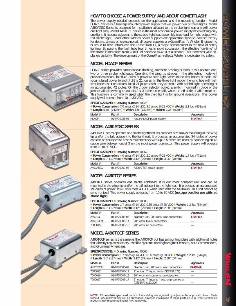
MODEL HDACF SERIESHDACF series provides simultaneous flashing, alternate flashing or both. It will operate one, two or three strobe lightheads. Operating the wing tip strobes in the alternating mode will provide an accumulated 42 joules of power to each light. When in the simultaneous mode, the accumulated power to each light is 21 joules. In the three light mode, the wing tips will flash simultaneous at an accumulated 21 joules each, they alternate with a third light operating at an accumulated 42 joules. On the trigger selector outlet, a switch mounted in place of the jumper will allow wing tip outlets 2 & 3 to be turned off, while the tail outlet 1 will remain on. This function is commonly used when the third light is for ground operations. This power supply will operate from 10 to 30 VDC.SPECIFICATIONS: ● Drawing Number: 70028● Power Consumption: 7.0 amps @ 14 VDC; 3.5 amps @ 28 VDC ● Weight: 2.1 lbs. (953gm)● Length: 5.50” (140mm) ● Width: 5.0” (127mm) ● Height: 2.37” (60mm)Model # Part # Description ApprovalsHDACF 01-0770028-05 A413AHDACF power supply FAA/PMA
MODEL A490ATSC SERIESA490ATSC series operates one strobe lighthead. Its compact size allows mounting in the wing tip and/or the tail, adjacent to the lighthead. It produces an accumulated 34 joules of power and can be equipped to flash simultaneously with up to 5 other like units by connecting an 18 gauge wire between outlet 3 on the input power connector. This power supply will operate from 10 to 30 VDC.SPECIFICATIONS: ● Drawing Number: 70062● Power Consumption: 4.0 amps @ 14 VDC; 2.0 amps @ 28 VDC ● Weight: 1.7 lbs. (771gm)● Length: 5.0” (127mm) ● Width: 3.12” (79mm) ● Height: 3.06” (78mm)Model # Part # Description ApprovalsA490ATSC 01-0770062-03 A490ATSCF power supply FAA/PMA
MODEL A490TCF SERIESA490TCF series operates one strobe lighthead. It is our most compact unit and can be mounted in the wing tip and/or the tail adjacent to the lighthead. It produces an accumulated 19 joules of power. It will only meet 400 CP when used with the A470A-W. This unit cannot be synchronized. This power supply operates from 10 to 30 VDC (not approved for use with red strobe light).SPECIFICATIONS: ● Drawing Number: 70006● Power Consumption: 1.7 amps @ 14 VDC; 0.85 amps @ 28 VDC ● Weight: 1.2 lbs. (544gm)● Length: 5.0” (127mm) ● Width: 3.12” (79mm) ● Height: 2.38” (60mm)Model # Part # Description ApprovalsA490TCF 01-0770006-08 Standard unit, 20” leads, amp connectors FAA/PMAA490TCFM 01-0770006-14 20” leads, Molex connectors —7000615 01-0770006-15 20” leads, no connectors —
MODEL A490TCCF SERIESA490TCCF series is the same as the A490TCF but has a mounting plate with additional holes that directly replaces factory installed systems on single engine Cessna’s, Aero Commanders, and Grumman Americans.SPECIFICATIONS: ● Drawing Number: 70006● Power Consumption: 1.7 amps @ 14 VDC; 0.85 amps @ 28 VDC ● Weight: 1.2 lbs. (544gm)● Length: 5.0” (127mm) ● Width: 3.12” (79mm) ● Height: 2.38” (60mm)Model # Part # Description ApprovalsA490TCCF 01-0770006-09 Standard unit, 20” leads, amp connectors FAA/PMA7000612 01-0770006-12 9” output, 7” input, leads (CESSNA 172) —7000616 01-0770006-16 20” leads, ms connector on output lead —7000617 01-0770006-17 3” output, 7” input & 4 pos. amp connector (CESSNA) (182,206) —
PO
WE
R S
UP
PL
IES
PO
WE
R S
UP
PL
IES
NOTE: All non-FAA approved parts in this catalog are signified by a (—) in the approval column. Parts without FAA approval may still be purchased, however, installation of these parts on U. S. Type Certificated products may require additional FAA approvals. 55

®
MODEL 90101 SERIES90101 series is similar to the HTCF but has military connectors. It is available in SingleFlash or CometFlash®. Several different configurations are available for application specific installa-tions.SPECIFICATIONS: ● Drawing Number: 90101● Power Consumption: 4 amps @ 14 VDC; 2 amps @ 28 VDC ● Weight: 1.7 lbs. (771gm)● Length: 5.0” (127mm) ● Width: 3.12” (79mm) ● Height: 3.50” (89mm)Model # Part # Description Approvals9010100 01-0790101-00 24 joule, SingleFlash FAA TSO-C96a9010101 01-0790101-01 24 joule, SingleFlash, old style mounting plate FAA TSO-C96a9010102 01-0790101-02 24 joule, SingleFlash, w/add on mounting plate FAA TSO-C96a9010104 01-0790101-04 34 joule, CometFlash, replaces Grimes 60- 2799 when used with mounting brackets FAA TSO-C96a9010105 01-0790101-05 34 joule, CometFlash FAA TSO-C96a
MODEL 90079 SERIES90079 series is similar to the HDACF series, but has military connectors. Connectors 2 & 3 (wing tips) will operate simultaneously and will alternate with connector 1 (tail). When operat-ing two lights, use connectors 1 & 2 to operate in the alternating mode.SPECIFICATIONS: ● Drawing Number: 90079● Power Consumption: 7 amps @14 VDC; 3.5 amps @28 VDC ● Weight: 2.3 lbs. (1043gm)● Length: 5.50” (140mm) ● Width: 5.0” (127mm) ● Height: 2.40” (61mm)Model # Part # Description Approvals9007904 01-0790079-04 42 joule, CometFlash, replaces Grimes 60-1750-1 & 3 FAA/PMA9007906 01-0790079-06 42 joule, CometFlash, socket outputs, with add on mounting brackets —
MODEL 90192 SERIES90192 series produces 34 joules of energy in CometFlash, and can be synchronized with up to 5 other like units by connecting with 18 gauge wire.SPECIFICATIONS: ● Drawing Number: 90192● Power Consumption: 4 amps @ 14 VDC; 2 amps @ 28 VDC ● Weight: 2.1 lbs. (953gm)● Length: 10.13” (257mm) ● Width: 3.54” (90mm) ● Height: 1.9” (48mm)Model # Part # Description Approvals9019201 01-0790192-01 Used on JPATS program, FAA TSO-C96a replaces Hella #8ES 007 046-01
MODEL HDHCF SERIESHDHCF series provides simultaneous flashing, alternate flashing or both (see HDACF for func-tions). It directly replaces factory installed units on Hughes 500 Series Helicopters. Unit can directly replace 60-1431 -1 & -3 power supplies without wiring or baseplate modifications. This power supply will operate from 10 to 30 VDC.SPECIFICATIONS: ● Drawing Number: 70117● Power Consumption: 7.0 amps @ 14 VDC; 3.5 amps @ 28 VDC ● Weight: 2.1 lbs. (953gm)● Length: 5.50” (140mm) ● Width: 5.0” (127mm) ● Height: 2.37” (60mm)Model # Part # Description ApprovalsHDHCF 01-0770117-01 Power supply A414AHDHCF FAA/PMA
MODEL HDS SERIESHDS series produces 20 joules of energy, SingleFlash, alternating between two light assem-blies. The SingleFlash allows for a low current draw. This power supply will operate from 10 to 30 VDC.SPECIFICATIONS: ● Drawing Number: 70169● Power Consumption: 4.0 amps @ 14 VDC; 2 amps @ 28 VDC ● Weight: 2.0 lbs. (907gm)● Length: 5.50” (140mm) ● Width: 5.0” (127mm) ● Height: 2.37” (60mm)Model # Part # Description ApprovalsHDS1428 01-0770169-03 Power supply A413AHDS —
MODEL C701881C701881 series produces 15 joules of energy, SingleFlash. It can be synchronized with other like units by connecting with 18 gauge wire. This power supply operates from 10 to 30 VDC. Beech/Raytheon P/N - 100-384118-21.SPECIFICATIONS: ● Drawing Number: 70188● Power Consumption: 1.5 amps @ 14 VDC; 0.75 amps @ 28 VDC ● Weight: 1.8 lbs. (816gm)● Length: 5.0” (127mm) ● Width: 3.12” (79mm) ● Height: 3.06” (78mm)Model # Part # Description ApprovalsC701881 01-0770188-00 Power supply —
PO
WE
R S
UP
PL
IES
PO
WE
R S
UP
PL
IES
NOTE: All non-FAA approved parts in this catalog are signified by a (—) in the approval column. Parts without FAA approval may still be purchased, however, installation of these parts on U. S. Type Certificated products may require additional FAA approvals.66
®
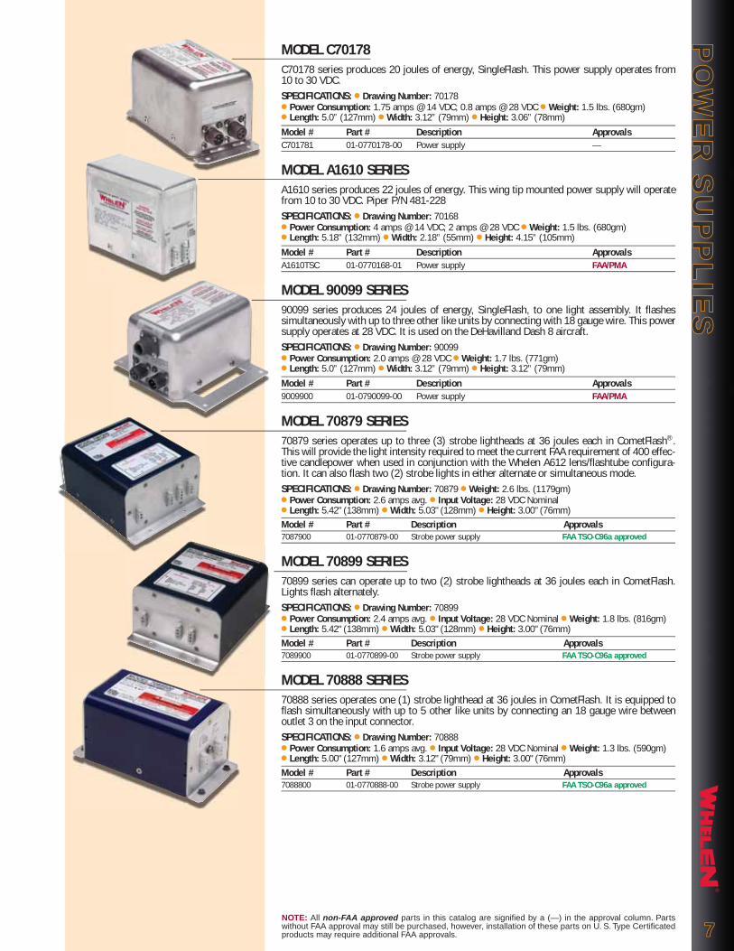
MODEL C70178C70178 series produces 20 joules of energy, SingleFlash. This power supply operates from 10 to 30 VDC.SPECIFICATIONS: ● Drawing Number: 70178● Power Consumption: 1.75 amps @ 14 VDC; 0.8 amps @ 28 VDC ● Weight: 1.5 lbs. (680gm) ● Length: 5.0” (127mm) ● Width: 3.12” (79mm) ● Height: 3.06” (78mm)Model # Part # Description ApprovalsC701781 01-0770178-00 Power supply —
MODEL A1610 SERIESA1610 series produces 22 joules of energy. This wing tip mounted power supply will operate from 10 to 30 VDC. Piper P/N 481-228SPECIFICATIONS: ● Drawing Number: 70168● Power Consumption: 4 amps @ 14 VDC; 2 amps @ 28 VDC ● Weight: 1.5 lbs. (680gm)● Length: 5.18” (132mm) ● Width: 2.18” (55mm) ● Height: 4.15” (105mm)Model # Part # Description ApprovalsA1610TSC 01-0770168-01 Power supply FAA/PMA
MODEL 90099 SERIES90099 series produces 24 joules of energy, SingleFlash, to one light assembly. It flashes simultaneously with up to three other like units by connecting with 18 gauge wire. This power supply operates at 28 VDC. It is used on the DeHavilland Dash 8 aircraft.SPECIFICATIONS: ● Drawing Number: 90099● Power Consumption: 2.0 amps @ 28 VDC ● Weight: 1.7 lbs. (771gm)● Length: 5.0” (127mm) ● Width: 3.12” (79mm) ● Height: 3.12” (79mm)Model # Part # Description Approvals9009900 01-0790099-00 Power supply FAA/PMA
MODEL 70879 SERIES70879 series operates up to three (3) strobe lightheads at 36 joules each in CometFlash®. This will provide the light intensity required to meet the current FAA requirement of 400 effec-tive candlepower when used in conjunction with the Whelen A612 lens/flashtube configura-tion. It can also flash two (2) strobe lights in either alternate or simultaneous mode.SPECIFICATIONS: ● Drawing Number: 70879 ● Weight: 2.6 lbs. (1179gm)● Power Consumption: 2.6 amps avg. ● Input Voltage: 28 VDC Nominal ● Length: 5.42" (138mm) ● Width: 5.03" (128mm) ● Height: 3.00" (76mm)Model # Part # Description Approvals7087900 01-0770879-00 Strobe power supply FAA TSO-C96a approved
MODEL 70899 SERIES70899 series can operate up to two (2) strobe lightheads at 36 joules each in CometFlash. Lights flash alternately.SPECIFICATIONS: ● Drawing Number: 70899● Power Consumption: 2.4 amps avg. ● Input Voltage: 28 VDC Nominal ● Weight: 1.8 lbs. (816gm)● Length: 5.42" (138mm) ● Width: 5.03" (128mm) ● Height: 3.00" (76mm)Model # Part # Description Approvals7089900 01-0770899-00 Strobe power supply FAA TSO-C96a approved
MODEL 70888 SERIES70888 series operates one (1) strobe lighthead at 36 joules in CometFlash. It is equipped to flash simultaneously with up to 5 other like units by connecting an 18 gauge wire between outlet 3 on the input connector. SPECIFICATIONS: ● Drawing Number: 70888● Power Consumption: 1.6 amps avg. ● Input Voltage: 28 VDC Nominal ● Weight: 1.3 lbs. (590gm)● Length: 5.00" (127mm) ● Width: 3.12" (79mm) ● Height: 3.00" (76mm)Model # Part # Description Approvals7088800 01-0770888-00 Strobe power supply FAA TSO-C96a approved
PO
WE
R S
UP
PL
IES
PO
WE
R S
UP
PL
IES
NOTE: All non-FAA approved parts in this catalog are signified by a (—) in the approval column. Parts without FAA approval may still be purchased, however, installation of these parts on U. S. Type Certificated products may require additional FAA approvals. 77

MODEL 90544, LED PATENTED TECHNOLOGY: REDUNDANT LIGHTING AND ONBOARD DIAGNOSTIX™
90544 series is Whelen's patented “two lights in one” with Diagnostix indication (Wing tip POS/ACL). The most modern inner wing lighting solution on the market today, designed to comply with FAA TSO-C96a Class II (400 ecp) anti-collision light requirements and TSO-C30c forward position light requirements. The LED's provide a significant reduction in current draw over conventional position light bulbs and strobe power supplies. Whelen LED designs virtu-ally eliminate EMI/RFI interference. Model 90544 analyzes circuit condition and can automati-cally compensate for any given partial circuit failure. Diagnostix indicator is viewable by ground personnel indicating the assembly is operating in redundant mode. Light remains FAA/TSO compliant during operation in a redundant mode! All current source and flasher cir-cuitry is contained within the current source / flasher box located in the wing (see Model 90547, call factory). Item ships with 38999 Series close out connector. 28 VDC Only.SPECIFICATIONS: ● Current: (Current Source / Flasher) POS: 0.25amps // ACL 0.6 Average, 3.0amps Peak ● Weight: 0.48 lbs (218gm) ● Lens: None ● Dimensions: 4.10" (104mm) Long, 2.10" (53mm) Wide, Overall Height: 3.94" (100mm)
Model # Part # Description Approvals (Pending)9054401 01-0790544-01 Redundant LED POS/ACL (green) FAA TSO-C96a / TSO-C30c Type II9054402 01-0790544-02 Redundant LED POS/ACL (red) FAA TSO-C96a / TSO-C30c Type I
MODEL 90541, LED PATENTED TECHNOLOGY: REDUNDANT LIGHTING AND ONBOARD DIAGNOSTIX™
90541 series is Whelen's patented “two lights in one” with Diagnostix indication (Tail POS/ACL Light). The most modern inner wing lighting solution on the market today, designed to comply with TSO-C96a Type III (400 ecp) anti-collision light requirements, and TSO-C30c aft position light requirements. The LED's provide a significant reduction in current draw over conventional position light bulbs and strobe power supplies. Whelen LED designs virtually eliminate EMI/RFI interference. Model 90541 analyzes circuit condition and can automatically compensate for any given partial circuit failure. Diagnostix indicator is viewable by ground personnel indicating the assembly is operating in redundant mode. Light remains FAA/TSO compliant during operation in a redundant mode! All current source and flasher circuitry is contained within the lighthead.SPECIFICATIONS: ● Current: POS: 0.25 amps // ACL: 0.6 amps Avg, 3.20 amps Peak ● Weight: 1.3 lbs. (590gm) ● Lens: None ● Dimensions: 7.17" (182mm) Overall Depth, 1.60" (41mm) Wide, 5.38" (137mm) Overall Height
Model # Part # Description Approvals (Pending)9054100 01-0790541-00 Redundant LED AFT POS/ACL FAA TSO-C96a / TSO-C30c Type III
MODEL 90475 ALL LED, FORWARD AND AFT POS/ACL ASSEMBLY 90475 series, a LED head assembly only, powered by Whelen Model 7123404 LED flasher / current source. Designed to be mounted within two feet of the lighthead. Unit complies with TSO-C96a Class II (400 ecp) anti-collision light requirements, and TSO-C30c forward posi-tion light requirements. Model 90475 (6.6" (168mm) Long x 1.8" (46mm) Wide is a down-sized version of our 2008 released 90358 (7.3" (185mm) Long x 2.6" (66mm) Wide. 90475 shares the exposed profile of Whelen 90400 (self-contained). Unit ships with 24" (61cm) of RF shielded wiring into a MS27473T12A98P connector. 28 VDC Only.SPECIFICATIONS: ● Current: See 7123404 (0.50 amps Fwd & Aft Pos), (0.75 amps Average ACL) ● Weight: 1.0 lbs. (454gm) ● Lens: Clear Polycarbonate ● Dimensions: 6.60" (168mm) Long, 1.83” (46mm) Wide ● Exposed Height: 2.22" (56mm)
Model # Part # Description Approvals9047501 01-0790475-01 LED Fwd/Aft POS/ACL (green) FAA TSO-C96a/TSO-C30c Types II & III9047502 01-0790475-02 LED Fwd/Aft POS/ACL (red) FAA TSO-C96a/TSO-C30c Types I & III9047600 07-290476-000 A600 to 90475 LED ACL adapter plate -
LIG
HT
HE
AD
SL
IGH
TH
EA
DS
NOTE: All non-FAA approved parts in this catalog are signified by a (—) in the approval column. Parts without FAA approval may still be purchased, however, installation of these parts on U. S. Type Certificated products may require additional FAA approvals.88
Flush Mount
FLASHER / CURRENT SOURCE LIGHTHEAD USED
Model 7123403 powers......... Model 71170 or Model 90482
Model 7123404 powers Model 90475
NEW!
NEW!
NEW!
o
5
®
®
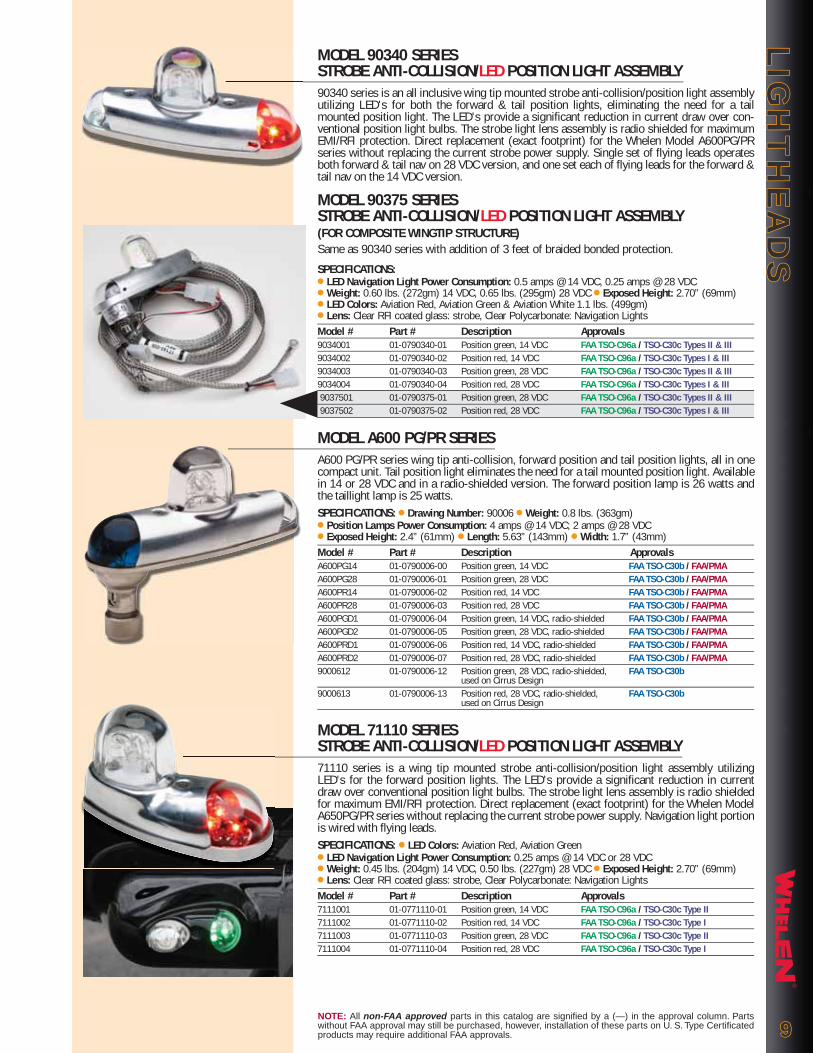
MODEL 90340 SERIES STROBE ANTI-COLLISION/LED POSITION LIGHT ASSEMBLY90340 series is an all inclusive wing tip mounted strobe anti-collision/position light assembly utilizing LED's for both the forward & tail position lights, eliminating the need for a tail mounted position light. The LED's provide a significant reduction in current draw over con-ventional position light bulbs. The strobe light lens assembly is radio shielded for maximum EMI/RFI protection. Direct replacement (exact footprint) for the Whelen Model A600PG/PR series without replacing the current strobe power supply. Single set of flying leads operates both forward & tail nav on 28 VDC version, and one set each of flying leads for the forward & tail nav on the 14 VDC version.
MODEL 90375 SERIESSTROBE ANTI-COLLISION/LED POSITION LIGHT ASSEMBLY (FOR COMPOSITE WINGTIP STRUCTURE)Same as 90340 series with addition of 3 feet of braided bonded protection.
SPECIFICATIONS:● LED Navigation Light Power Consumption: 0.5 amps @ 14 VDC, 0.25 amps @ 28 VDC ● Weight: 0.60 lbs. (272gm) 14 VDC, 0.65 lbs. (295gm) 28 VDC ● Exposed Height: 2.70” (69mm) ● LED Colors: Aviation Red, Aviation Green & Aviation White 1.1 lbs. (499gm)● Lens: Clear RFI coated glass: strobe, Clear Polycarbonate: Navigation LightsModel # Part # Description Approvals9034001 01-0790340-01 Position green, 14 VDC FAA TSO-C96a / TSO-C30c Types II & III9034002 01-0790340-02 Position red, 14 VDC FAA TSO-C96a / TSO-C30c Types I & III9034003 01-0790340-03 Position green, 28 VDC FAA TSO-C96a / TSO-C30c Types II & III9034004 01-0790340-04 Position red, 28 VDC FAA TSO-C96a / TSO-C30c Types I & III 9037501 01-0790375-01 Position green, 28 VDC FAA TSO-C96a / TSO-C30c Types II & III 9037502 01-0790375-02 Position red, 28 VDC FAA TSO-C96a / TSO-C30c Types I & III
MODEL A600 PG/PR SERIESA600 PG/PR series wing tip anti-collision, forward position and tail position lights, all in one compact unit. Tail position light eliminates the need for a tail mounted position light. Available in 14 or 28 VDC and in a radio-shielded version. The forward position lamp is 26 watts and the taillight lamp is 25 watts.SPECIFICATIONS: ● Drawing Number: 90006 ● Weight: 0.8 lbs. (363gm)● Position Lamps Power Consumption: 4 amps @ 14 VDC; 2 amps @ 28 VDC ● Exposed Height: 2.4” (61mm) ● Length: 5.63” (143mm) ● Width: 1.7” (43mm)Model # Part # Description ApprovalsA600PG14 01-0790006-00 Position green, 14 VDC FAA TSO-C30b / FAA/PMAA600PG28 01-0790006-01 Position green, 28 VDC FAA TSO-C30b / FAA/PMAA600PR14 01-0790006-02 Position red, 14 VDC FAA TSO-C30b / FAA/PMAA600PR28 01-0790006-03 Position red, 28 VDC FAA TSO-C30b / FAA/PMAA600PGD1 01-0790006-04 Position green, 14 VDC, radio-shielded FAA TSO-C30b / FAA/PMAA600PGD2 01-0790006-05 Position green, 28 VDC, radio-shielded FAA TSO-C30b / FAA/PMAA600PRD1 01-0790006-06 Position red, 14 VDC, radio-shielded FAA TSO-C30b / FAA/PMAA600PRD2 01-0790006-07 Position red, 28 VDC, radio-shielded FAA TSO-C30b / FAA/PMA9000612 01-0790006-12 Position green, 28 VDC, radio-shielded, FAA TSO-C30b used on Cirrus Design9000613 01-0790006-13 Position red, 28 VDC, radio-shielded, FAA TSO-C30b used on Cirrus Design
MODEL 71110 SERIESSTROBE ANTI-COLLISION/LED POSITION LIGHT ASSEMBLY71110 series is a wing tip mounted strobe anti-collision/position light assembly utilizing LED's for the forward position lights. The LED's provide a significant reduction in current draw over conventional position light bulbs. The strobe light lens assembly is radio shielded for maximum EMI/RFI protection. Direct replacement (exact footprint) for the Whelen Model A650PG/PR series without replacing the current strobe power supply. Navigation light portion is wired with flying leads. SPECIFICATIONS: ● LED Colors: Aviation Red, Aviation Green ● LED Navigation Light Power Consumption: 0.25 amps @ 14 VDC or 28 VDC● Weight: 0.45 lbs. (204gm) 14 VDC, 0.50 lbs. (227gm) 28 VDC ● Exposed Height: 2.70” (69mm) ● Lens: Clear RFI coated glass: strobe, Clear Polycarbonate: Navigation LightsModel # Part # Description Approvals7111001 01-0771110-01 Position green, 14 VDC FAA TSO-C96a / TSO-C30c Type II7111002 01-0771110-02 Position red, 14 VDC FAA TSO-C96a / TSO-C30c Type I7111003 01-0771110-03 Position green, 28 VDC FAA TSO-C96a / TSO-C30c Type II7111004 01-0771110-04 Position red, 28 VDC FAA TSO-C96a / TSO-C30c Type I
LIG
HT
HE
AD
SL
IGH
TH
EA
DS
NOTE: All non-FAA approved parts in this catalog are signified by a (—) in the approval column. Parts without FAA approval may still be purchased, however, installation of these parts on U. S. Type Certificated products may require additional FAA approvals. 99

®
MODEL A650 PG/PR SERIESA650 PG/PR series wing tip with anti-collision & forward position lights can be used to con-vert non-Whelen position lights into a position/anti-collision light system. The small size allows for mounting into a wing tip enclosure. Available in 14 or 28 VDC and in a radio-shielded version. The forward position lamp is 26 watts. SPECIFICATIONS: ● Drawing Number: 70054 ● Weight: 0.6 lbs. (272gm)● Position Lamp Power Consumption: 2 amps @ 14 VDC; 1 Amp @ 28 VDC● Exposed Height: 2.4” (61mm) ● Length: 4.0” (102mm) ● Width: 1.7” (43mm)Model # Part # Description ApprovalsA650PG14 01-0770054-00 Position green, 14 VDC FAA/PMAA650PG28 01-0770054-01 Position green, 28 VDC FAA/PMAA650PR14 01-0770054-02 Position red, 14 VDC FAA/PMAA650PR28 01-0770054-03 Position red, 28 VDC FAA/PMAA650PGD1 01-0770054-04 Position green, 14 VDC, radio-shielded FAA/PMAA650PGD2 01-0770054-05 Position green, 28 VDC, radio-shielded FAA/PMAA650PRD1 01-0770054-06 Position red, 14 VDC, radio-shielded FAA/PMAA650PRD2 01-0770054-07 Position red, 28 VDC, radio-shielded FAA/PMA
MODEL 71170 SERIES LED ANTI-COLLISION/FORWARD POSITION LIGHT ASSEMBLY...Now with Integrated Ground Recognition Light.71170 series is upgraded! An all LED forward position and anti-collision light assembly includes a red flashing portion to be used as a ground recognition light, red "ground recogni-tion light" cannot be activated simultaneously with white ACL light. This light intended for use as a system with 9048200 and 7123403 Series lightheads and flasher/current sources. Unit complies with TSO-C96a Class II (400 ecp) anti-collision light requirements, and TSO-C30c forward position light requirements. Input connector: MIL D38999 attached to a 24 inch har-ness attached to the rear of the assembly.SPECIFICATIONS: ● Current: ACL: 0.60 amps Average, 3.0 a Peak // POS: 0.25a // GND REC: 0.15a● Weight: 1.0 lbs. (454gm) ● Lens: Clear Polycarbonate ● Dimensions: 3.86" (98mm) Long, 1.77" (50mm) Wide ● Exposed Height: 2.33" (59mm) ● Input connector: MIL D38999 attached to a 24inch harness attached to the rear of the assembly.Model # Part # Description Approvals Pending7117001 01-0771170-01 LED POS (green)/ACL (white), GND REC (red) FAA TSO-C96a / TSO-C30c7117002 01-0771170-02 LED POS(red)/ACL (white), GND REC (red) FAA TSO-C96a / TSO-C30c
MODEL 71234 SERIES FLASHER/CURRENT SOURCE ASSEMBLY71234 series is a flasher/current source assembly designed to operate remote mounted LED anti-collision and position lights (7117001/-02 & 9048200). Model 90475 operates with 7123404. Unit complies with TSO-C96a Class II (400 ecp) anti-collision light requirements, and TSO-C30c tail position light requirements.SPECIFICATIONS: ● Power Consumption: 0.6 amps avg. 3 amps Peak @ 0.25 sec. 28 VDC● Weight: 0.5 lbs. (363gm) ● Height: 1.38" (35mm) ● Width: 3.67" (93mm)● Overall Depth: 4.60." (117mm) ● Input connector: MIL D38999/20FB5PNModel # Part # Description Approvals7123403 01-0771234-03 Flasher current source assembly FAA TSO-C96a / TSO-C30c7123404 01-0771234-04 Flasher current source assembly FAA TSO-C96a / TSO-C30c
MODEL A650 SERIESA650 series converts W1285 position lights into a position/anti-collision system by removing the existing retainer & replacing it with the A650 assembly. Radio-shielded version available.SPECIFICATIONS: ● Drawing No: 70053 ● Weight: 0.2 lbs. (91gm) ● Exposed Height: 2.4” (61mm)
Model # Part # Description ApprovalsA650 01-0770053-00 Standard unit FAA/PMAA650D 01-0770053-13 Radio-shielded FAA/PMA
MODEL A625 SERIESA625 series has many different applications. It can be used for aircraft with tip-tanks with enclosed position lights (under a fairing), or as an add-on strobe on the wing or the tail. Available in a radio-shielded version.SPECIFICATIONS: ● Drawing No: 70058 ● Weight: 0.2 lbs. (91gm) ● Exposed Height: 1.7” (43mm)
Model # Part # Description ApprovalsA625 01-0770058-03 Standard unit, clear lens FAA/PMAA625D 01-0770058-13 Radio-shielded, clear lens FAA/PMAA625R 01-0770058-04 Standard unit, red lens —A625DR 01-0770058-14 Radio-shielded, red lens —7005815 01-0770058-15 Radio-shielded, 3/c cable, 12” ground braid —7005816 01-0770058-16 Radio-shielded, 24” 3/c cable, w/MS connector —
LIG
HT
HE
AD
SL
IGH
TH
EA
DS
1010NOTE: All non-FAA approved parts in this catalog are signified by a (—) in the approval column. Parts without FAA approval may still be purchased, however, installation of these parts on U. S. Type Certificated products may require additional FAA approvals.
NEW!
NEW!
NEW!

®
MODEL 70821 SERIES70821 series remote streamlined strobe light assembly. Easily mounted on the wing tip for anti-collision or on the vertical fin for ground recognition. It is recommended for the wing tips on Cessna single engine aircraft 1970-71. Its sleek aerodynamic shape allows it to be mount-ed where surface area is at a premium, or to simply “clean-up” the look of the airplane. It can be added as a low profile ground recognition light when mounted on the vertical fin or fuse-lage. A mounting adapter plate facilitates mounting.SPECIFICATIONS: ● Drawing Number: 70821 ● Weight: 0.3 lbs. (136gm)● Exposed Height: 1.8” (46mm) ● Length: 3.5 (89mm) ● Width: 1.8” (46mm)Model # Part # Description Approvals7082100 01-0770821-00 Standard unit, clear lens —7082101 01-0770821-01 Radio-shielded, clear lens —7082102 01-0770821-02 Standard unit, red lens —7082103 01-0770821-03 Radio-shielded, red lens —
MODEL 50626 SERIES STROBE TUBE ASSEMBLY50626 series strobe tube assemblies are used with the following model numbers listed in chart below:Model # Part # Description Used on5062600 36-0050626-00 Strobe tube assembly. 6" long Model 90111025062601 36-0050626-01 Strobe tube assy. 6" long w/grommet Model 9034000 thru 07, 20, 21 Model 7111001 thru 045062602 36-0050626-02 Strobe tube assy. 12.5" long w/grommet Model 9034008, 095062603 36-0050626-00 Strobe tube assy. 2" long w/grommet Model 9037501, 02
MODELS A610 & A612A610 flash tube and A612 glass lens are used for installing wing tip strobes in single engine Cessna’s 1972 and later. The existing position light retainer is modified to accommodate the lens, and the flash tube is mounted directly behind. The unique magnifying design of the A612 lens increases the light intensity by two to three times in the horizontal plane. These items may be used for custom installations or as spare parts for existing light assemblies. The A612 lens is available in Aviation Red and an RFI coated version. Lenses meet material require-ments of MIL-C-7989B Class B.SPECIFICATIONS: ● Drawing Number A610: 50276 ● Drawing Number A612: 90005● A610 Flash Tube Weight: 0.09 lbs. (41gm) ● A612 Lens Weight: 0.08 lbs. (36gm)Model # Part # Description ApprovalsA610 02-0250276-00 Standard unit, 6” leads FAA/PMAA610M 02-0250276-03 Molex connector, 6” leads FAA/PMA5027601 02-0250276-01 14” leads FAA/PMA5027602 02-0250276-02 12.5” leads FAA/PMAA612 68-2290005-30 Standard clear lens FAA/PMAA612D 68-2290005-34 Radio-shielded, clear lens —A612R 68-2290005-50 Standard red lens —A612DR 68-2290005-54 Radio-shielded, red lens —
MODEL 90482 SERIES LED ANTI-COLLISION/TAIL POSITION LIGHT ASSEMBLY, INTEGRATED GROUND RECOGNITION LIGHT90482 series is a compact and feature added version of the 90354 tail assembly (shown in 2008 catalog). Aft position light with white anti-collision light combination to include a red flashing portion used as a ground recognition light red ground recognition and white anti-collision lighting can not be activated simultaneously. This light intended for use as a system with 71170( ) and 7123403 Series lightheads and flasher/current sources for complete air-craft coverage. Item does not include interconnect cable for flasher/current source.SPECIFICATIONS: ● Current (7123403): ACL: 0.53A Average, 2.5 a Peak // POS: 0.25a // Ground Rec. 0.15a ● Weight: 0.35 lbs. (159gm) ● Lens: Clear Polycarbonate ● Dimensions: 1.78" (45mm) Deep, 1.25" (32mm) Wide ● Exposed Height: 3.60" (91mm)
Model # Part # Description Approvals (Pending)9048200 01-0790482-00 Aft POS/ACL (white) with GND REC (red) FAA TSO C96a / TSO-C30c Type III
LIG
HT
HE
AD
SL
IGH
TH
EA
DS
NOTE: All non-FAA approved parts in this catalog are signified by a (—) in the approval column. Parts without FAA approval may still be purchased, however, installation of these parts on U. S. Type Certificated products may require additional FAA approvals. 1111
A612
A610
50626
NEW!

®
MODEL A500A SERIESA500A series combination strobe/tail navigation light used when the wing tip anti-collision lights are mounted in an enclosure and can’t provide 360º of strobe coverage. It is a direct replacement for the standard tail position light. Available in a radio-shielded version. Voltage (14 or 28) and mounting (horizontal or vertical) must be specified when ordering.SPECIFICATIONS: ● Drawing Number: 70024● Weight: 0.3 lbs. (136gm) ● Exposed Height: 1.7” (43mm) ● Diameter: 1.5” (38mm)Model # Part # Description ApprovalsA500AV14 01-0770024-00 Vertical mount, 14 VDC FAA/PMA, FAA TSO-C30bA500AV28 01-0770024-01 Vertical mount, 28 VDC FAA/PMA, FAA TSO-C30bA500AH14 01-0770024-02 Horizontal mount, 14 VDC FAA/PMA, FAA TSO-C30bA500AH28 01-0770024-03 Horizontal mount, 28 VDC FAA/PMA, FAA TSO-C30bA500AVD1 01-0770024-04 Vertical mount, 14 VDC, radio-shielded FAA/PMA, FAA TSO-C30bA500AVD2 01-0770024-05 Vertical mount, 28 VDC, radio-shielded FAA/PMA, FAA TSO-C30bA500AHD1 01-0770024-06 Horizontal mount, 14 VDC, radio-shielded FAA/PMA, FAA TSO-C30bA500AHD2 01-0770024-07 Horizontal mount, 28 VDC, radio shielded FAA/PMA, FAA TSO-C30bA500ASP2 01-0770024-25 Vertical mount, 28 VDC, 50” cables, — no connectorsA500ABV1 01-0770024-16 Beech Special 14 VDC, MS connector —A500ABV2 01-0770024-15 Beech Special 24 VDC, MS connector —
MODEL A470A SERIESA470A series remote strobe light assembly is compatible with all Whelen power supplies. It can be installed on the fuselage or the vertical fin. The unique polycarbonate optic lens and reflector design, re-directs stray light rays into the horizontal plane to provide the maximum 360º of uniform light coverage possible. Available in three different lens colors, aviation red, aviation white and split aviation red/white. Available in radio-shielded configurations. All assemblies require either the model H102 or H103 mounting adapter.SPECIFICATIONS: ● Drawing Number: 70019● Weight: 0.3 lbs. (136gm) ● Exposed Height: 3.75” (95mm) ● Diameter: 2.5” (64mm)Model # Part # Description ApprovalsA470AR 01-0770019-18 Standard assembly, red lens FAA/PMAA470AW 01-0770019-19 Standard assembly, white lens FAA/PMAA470AS 01-0770019-20 Standard assembly, split red/white lens FAA/PMAA470ADR 01-0770019-21 Radio-shielded assembly, red lens FAA/PMAA470ADW 01-0770019-22 Radio-shielded assembly, white lens FAA/PMAA470ADS 01-0770019-23 Radio-shielded assembly, split red/white lens FAA/PMA
LIG
HT
HE
AD
SL
IGH
TH
EA
DS
NOTE: All non-FAA approved parts in this catalog are signified by a (—) in the approval column. Parts without FAA approval may still be purchased, however, installation of these parts on U. S. Type Certificated products may require additional FAA approvals.1212
* A469A-DOLD
A470DOLD STYLE
A402OLD
OLD STYLERADIO SHIELDED RADIO SHIELDED
A469BNEW
A470ADNEW
RADIO SHIELDEDGASKET ( )NEW
NEW STYLE
A402ADNEW
NOTE -* THE A469AD SHIELDED FLASH TUBE ASSEMBLY CAN NOT BE USED WITH: The new A470AD Remote Strobe Head Assembly as shown, the new A402AD Lens, or the new HR,DFA Self Contained Strobe Light Assembly.
Note: 06-190125 is not the part number for the A469B but a mold number, order A469B
See Aviation Installation Guide for more information.
HORIZONTAL MOUNTING
VERTICAL MOUNTING

®
MODELS H102 & H103Designed for the model A470A or model A450 series remote strobe lighthead assemblies. The model H102 allows flush mounting of the lighthead to the skin of the fuselage or the vertical stabilizer on later model Cessna Single engines. The H103 is designed for strobe assemblies to be installed in the standard 3-3/4” (95mm) dia. rotating beacon mounting hole.SPECIFICATIONS: ● Drawing Number H102: 30068 ● Drawing Number H103: 30079
Model # Part # Description ApprovalsH102 07-730068-000 Flush mount adapter FAA/PMAH103 11-230079-000 Rotating beacon mount adapter —
MODEL A450 SERIESA450 series remote strobe light assembly is compatible with all Whelen power supplies. It can be installed on the fuselage or the vertical fin. The Pyrex® Glass lens (clear only) makes the assembly suitable for use in severe vibration, chemical and moisture conditions (i.e. agri-cultural aircraft). Requires either the model H102 or model H103 mounting adapter.SPECIFICATIONS: ● Drawing Number: 70032● Weight: 0.3 lbs. (136gm) ● Exposed Height: 2.25” (57mm) ● Diameter: 2.5” (64mm)Model # Part # Description ApprovalsA450 01-0770032-00 Standard assembly, clear lens FAA/PMA
MODEL 90111 SERIES90111 series remote strobe light assembly compatible with all Whelen power supplies. Can be installed on the wing tip or the tail.SPECIFICATIONS: ● Drawing Number: 90111 ● Weight: 0.5 lbs. (227gm)● Exposed Height: 2.08” (53mm) ● Width: 1.75” (44mm) ● Length: 2.5” (64mm)Model # Part # Description Approvals9011100 01-0790111-00 Shielded, clear lens (BeechJet) —9011102 01-0790111-02 Shielded, masked red lens (Piper) FAA/PMA
MODEL 90028 SERIES90028 series wing tip strobe light used on Beech aircraft with common-ality wing tip 1974 & later. It is a direct replacement for 30-0467-( ), 30-1331-( ) and the 30-1467-( ) series.
SPECIFICATIONS: ● Drawing Number: 90028 ● Weight: 0.4 lbs. (181gm)● Exposed Height: 1.87” (48mm) ● Length: 4.37” (111mm) ● Depth: 2.25” (57mm)Model # Part # Description Approvals9002800 01-0790028-00 Replacement flash tube assembly, unpainted —9002801 01-0790028-01 Replacement flash tube assembly, painted (white) —D900283 01-0790028-03 Wing tip light assembly, 45º mounting bracket —D900285 01-0790028-05 Taillight assembly, 90º mounting bracket —D900287 01-0790028-07 Wing tip light assembly, 45º mtg. bracket, MS connector —D900289 01-0790028-09 Taillight assembly, 90º mounting bracket, MS connector —
MODEL 90102 SERIES90102 series dual radio-shielded wing tip strobe light designed with two lights for wing tip strobe redundancy. It is used on DeHavilland Dash 8 aircraft.SPECIFICATIONS: ● Drawing Number: 90102● Weight: 1.0 lbs. (454gm) ● Height: 2.78” (71mm) ● Length: 5.7” (145mm) ● Width: 2.4” (61mm)Model # Part # Description Approvals9010200 01-0790102-00 Dual radio-shielded wing tip strobe light FAA/PMA
MODEL 90104 SERIES90104 series dual radio-shielded tail strobe light designed with two lights for tail strobe redundancy for DeHavilland Dash 8 aircraft.SPECIFICATIONS: ● Drawing Number: 90104● Weight: 1.0 lbs. (454gm) ● Height: 2.78” (71mm) ● Length: 6.7” (170mm) ● Width: 2.9” (74mm)Model # Part # Description Approvals9010400 01-0790104-00 Dual radio-shielded tail strobe light FAA/PMA
LIG
HT
HE
AD
SL
IGH
TH
EA
DS
NOTE: All non-FAA approved parts in this catalog are signified by a (—) in the approval column. Parts without FAA approval may still be purchased, however, installation of these parts on U. S. Type Certificated products may require additional FAA approvals. 1313
H102H103
®
LIG
HT
HE
AD
SL
IGH
TH
EA
DS
1414
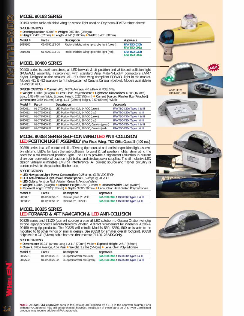
MODEL 90193 SERIES90193 series radio-shielded wing tip strobe light used on Raytheon JPATS trainer aircraft.SPECIFICATIONS:● Drawing Number: 90193 ● Weight: 0.57 lbs. (259gm)● Height: 2.46” (62mm) ● Length: 4.74” (120mm) ● Width: 3.45” (88mm)Model # Part # Description Approvals9019300 01-0790193-00 Radio-shielded wing tip strobe light (green) FAA TSO-C30b FAA TSO-C96a9019301 01-0790193-01 Radio-shielded wing tip strobe light (red) FAA TSO-C30b FAA TSO-C96a
MODEL 90400 SERIES90400 series is a self-contained, all LED forward & aft position and white anti-collision light (POS/ACL) assembly. Interconnect with standard Amp Mate-N-Lock® connectors (A447 Style). Designed as the smallest, all-LED, fixed wing compliant POS/ACL light in the market. Models -91 & -92 available to fit hole pattern of Cessna Caravan (below). Models available in 14 and 28 VDC.SPECIFICATIONS: ● Current: ACL: 0.87A Average, 4.0 a Peak // POS: 0.5a● Weight: 1.0 lbs. (454gm) ● Lens: Clear Polycarbonate ● Lighthead Dimensions: 6.60" (168mm) Long, 1.83 (46mm) Wide, Exposed Height, 2.22" (56mm) ● Current Source / Flasher Box (Attached) Dimensions: 3.59" (91mm) Long, 1.11" (28mm) Height, 3.50 (89mm) WidthModel # Part # Description Approvals9040011 01-0790400-11 LED Position/Anti-Coll, 14 VDC (green) FAA TSO-C30c Types II & III9040012 01-0790400-12 LED Position/Anti-Coll, 14 VDC (red) FAA TSO-C30c Types I & III9040021 01-0790400-21 LED Position/Anti-Coll, 28 VDC (green) FAA TSO-C30c Types II & III9040022 01-0790400-22 LED Position/Anti-Coll, 28 VDC (red) FAA TSO-C30c Types I & III9040091 01-0790400-91 LED Position/Anti-Coll, 28 VDC, Caravan (green) FAA TSO-C30c Types II & III9040092 01-0790400-92 LED Position/Anti-Coll, 28 VDC, Caravan (red) FAA TSO-C30c Types I & III
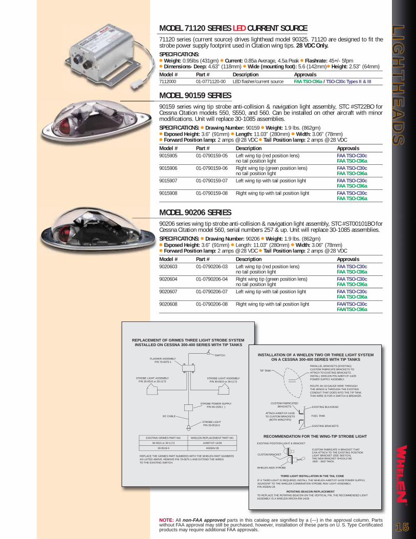
MODEL 90358 SERIES SELF-CONTAINED LED ANTI-COLLISION/LED POSITION LIGHT ASSEMBLY (For Fixed Wing, TSO-C96a Class II (400 ecp)
90358 series is a self-contained all LED wing tip mounted anti-collision/position light assem-bly utilizing LED's for both the anti-collision, forward & tail position lights, eliminating the need for a tail mounted position light. The LED's provide a significant reduction in current draw over conventional position light bulbs, and strobe power supplies. The all inclusive LED design virtually eliminates EMI/RFI interference. All current source and flasher circuitry is contained within the attached flasher box.SPECIFICATIONS:● LED Navigation Light Power Consumption: 0.25 amps @ 28 VDC EACH● LED Anti-Collision Light Power Consumption: 0.5 amps @ 28 VDC ● LED Colors: Aviation Red, Aviation Green & Aviation White ● Weight: 1.3 lbs. (590gm) ● Exposed Height: 2.80" (71mm) ● Exposed Width: 2.64" (67mm) ● Exposed Length: 7.29" (185mm) ● Depth: 3.00" (76mm) ● Lens: Clear Hard Coated PolycarbonateModel # Part # Description Approvals9035801 01-0790358-01 Position green, 28 VDC FAA TSO-C96a / TSO-C30c Types II & III9035802 01-0790358-02 Position red, 28 VDC FAA TSO-C96a / TSO-C30c Types I & III
MODEL 90325 SERIES LED FORWARD & AFT NAVIGATION & LED ANTI-COLLISION90325 series and 71120 (current source) are an all LED solution to Cessna Citation wingtip strobe legacy products manufactured by Whelen. A direct replacement for Whelen’s 90206 & 90159 wing tip products. The 90325 will retrofit Models 550, S550, 560 or is able to be modified to fit other wings of similar design. See 90358 for smaller overall footprint. 90358 ships with a 24” (61cm) cable harness that mate to 71120. 28 VDC Only.SPECIFICATIONS:● Dimensions: 10.24” (6mm) Long x 3.11” (79mm) Wide ● Exposed Height: 2.61” (66mm)● Current: 0.85a Average, 4.5a Peak ● Weight: 1.2 lbs (544gm) ● Lens: Clear Polycarbonate Model # Part # Description Approvals9032501 01-0790325-01 LED position/anti-coll (red) FAA TSO-C96a / TSO-C30c Types I & III9032502 01-0790325-02 LED position/anti-coll (green) FAA TSO-C96a / TSO-C30c Types II & III
NOTE: All non-FAA approved parts in this catalog are signified by a (—) in the approval column. Parts without FAA approval may still be purchased, however, installation of these parts on U. S. Type Certificated products may require additional FAA approvals.
White LED’s with Clear Lens
NEW!
®
LIG
HT
HE
AD
SL
IGH
TH
EA
DS
1515
MODEL 71120 SERIES LED CURRENT SOURCE71120 series (current source) drives lighthead model 90325. 71120 are designed to fit the strobe power supply footprint used in Citation wing tips. 28 VDC Only.SPECIFICATIONS:● Weight: 0.95lbs (431gm) ● Current: 0.85a Average, 4.5a Peak ● Flashrate: 45+/- 5fpm● Dimensions- Deep: 4.63” (118mm) ● Wide (mounting foot): 5.6 (142mm)● Height: 2.53” (64mm)Model # Part # Description Approvals7112000 01-0771120-00 LED flasher/current source FAA TSO-C96a / TSO-C30c Types II & III
MODEL 90159 SERIES90159 series wing tip strobe anti-collision & navigation light assembly, STC #ST22BO for Cessna Citation models 550, S550, and 560. Can be installed on other aircraft with minor modifications. Unit will replace 30-1085 assemblies.SPECIFICATIONS: ● Drawing Number: 90159 ● Weight: 1.9 lbs. (862gm)● Exposed Height: 3.6” (91mm) ● Length: 11.03” (280mm) ● Width: 3.06” (78mm) ● Forward Position lamp: 2 amps @ 28 VDC ● Tail Position lamp: 2 amps @ 28 VDCModel # Part # Description Approvals9015905 01-0790159-05 Left wing tip (red position lens) FAA TSO-C30c no tail position light FAA TSO-C96a9015906 01-0790159-06 Right wing tip (green position lens) FAA TSO-C30c no tail position light FAA TSO-C96a9015907 01-0790159-07 Left wing tip with tail position light FAA TSO-C30c FAA TSO-C96a9015908 01-0790159-08 Right wing tip with tail position light FAA TSO-C30c FAA TSO-C96a
MODEL 90206 SERIES90206 series wing tip strobe anti-collision & navigation light assembly, STC #ST00101BO for Cessna Citation model 560, serial numbers 257 & up. Unit will replace 30-1085 assemblies.SPECIFICATIONS: ● Drawing Number: 90206 ● Weight: 1.9 lbs. (862gm)● Exposed Height: 3.6” (91mm) ● Length: 11.03” (280mm) ● Width: 3.06” (78mm) ● Forward Position lamp: 2 amps @ 28 VDC ● Tail Position lamp: 2 amps @ 28 VDCModel # Part # Description Approvals9020603 01-0790206-03 Left wing tip (red position lens) FAA TSO-C30c no tail position light FAA TSO-C96a9020604 01-0790206-04 Right wing tip (green position lens) FAA TSO-C30c no tail position light FAA TSO-C96a9020607 01-0790206-07 Left wing tip with tail position light FAA TSO-C30c FAA TSO-C96a9020608 01-0790206-08 Right wing tip with tail position light FAA/TSO-C30c FAA/TSO-C96a
NOTE: All non-FAA approved parts in this catalog are signified by a (—) in the approval column. Parts without FAA approval may still be purchased, however, installation of these parts on U. S. Type Certificated products may require additional FAA approvals.
REPLACEMENT OF GRIMES THREE LIGHT STROBE SYSTEMINSTALLED ON CESSNA 300-400 SERIES WITH TIP TANKS
SWITCHFLASHER ASSEMBLY
P/N 70-0075-1
STROBE LIGHT ASSEMBLYP/N 30-0515 or 30-1172
STROBE LIGHT ASSEMBLYP/N 30-0515 or 30-1172
STROBE POWER SUPPLYP/N 60-1520-( )
3/C CABLE
STROBE LIGHTP/N 30-0516-5
REPLACE THE GRIMES PART NUMBERS WITH THE WHELEN PART NUMBERSAS LISTED ABOVE. REMOVE P/N 70-0075-1 AND EXTEND THE WIRESTO THE EXISTING SWITCH.
EXISTING GRIMES PART NO.
30-0515 or 30-1172
30-0516-5
WHELEN REPLACEMENT PART NO.
A490T-CF-14/28
A500AV-28
INSTALLATION OF A WHELEN TWO OR THREE LIGHT SYSTEMON A CESSNA 300-400 SERIES WITH TIP TANKS
EXISTING BULKHEAD
TIP TANK
PARALLEL BRACKETS (EXISTING)CUSTOM FABRICATE BRACKETS TOATTACH TO EXISTING BRACKETS.INSTALL WHELEN P/N A490T-CF-14/28POWER SUPPLY ASSEMBLY.
ROUTE AN 18 GAUGE WIRE THROUGHTHE WINGS & THROUGH THE EXISTINGCONDUIT THAT GOES INTO THE TIP TANK.THIS WIRE IS FOR A SWITCH & BREAKER.
CUSTOM FABRICATEDBRACKETS
ATTACH A490T-CF-14/28TO CUSTOM BRACKETS
(BOTH WINGTIPS)
THIRD LIGHT INSTALLATION IN THE TAIL CONE
EXISTING POSITION LIGHT & BRACKET
CUSTOM FABRICATE A BRACKET THAT CAN ATTACH TO THE EXISTING POSITION LIGHT BRACKET (SEE SKETCH). THE NEW BRACKET SHOULD BE.050î - .062î THICK.
FUEL TANK
EXISTING BRACKETS
RECOMMENDATION FOR THE WING-TIP STROBE LIGHT
CUSTOM BRACKET
WHELEN A625 STROBE
IF A THIRD LIGHT IS REQUIRED, INSTALL THE WHELEN A490T-CF-14/28 POWER SUPPLY, ADJACENT TO THE WHELEN COMBINATION STROBE /NAV LIGHT ASSEMBLY, P/N A500AV-28
ROTATING BEACON REPLACEMENTTO REPLACE THE ROTATING BEACON ON THE VERTICAL FIN, THE RECOMMENDED LIGHTASSEMBLY IS A WHELEN HRCFA-RW-14/28

®
SE
LF
-CO
NT
AIN
ED
LIG
HT
AS
SE
MB
LIE
SS
EL
F-C
ON
TA
INE
D L
IGH
T A
SS
EM
BL
IES MODEL 70900 SERIES LED BEACONS (for fixed wing aircraft)
70900 series are FAA TSO compliant self-contained anti-collision lights for fixed wing aircraft. An external power unit is not required. Conservative lab life results greater than 20,000 hours. No EMI or RFI produced. All units meet the minimum requirements stated in FAR Parts 23 & 25 for anti-collision light systems used on fixed wing aircraft, Ref; Class III (100 effective candela) of SAE AS8017a minimum performance standards. STC SA615EA approved.
Models 7090004 & 7090005 are designed to replace existing light assemblies with the 3-3/4” (95mm) dia. mounting pattern (Ref. Whelen HRCFA series, 90081 series, and “old style” rotating beacons). Same mounting hole pattern, no modification to the aircraft is required.SPECIFICATIONS: ● Power Consumption: P/N 01-0770900-04: 0.85 amps @ 14 VDC● Power Consumption: P/N 01-0770900-05: 0.425 amps @ 28 VDC ● LED Color: Aviation Red ● Weight: 1.1 lbs. (499gm) ● Exposed Height: 3.1” (78mm) ● Exposed Diameter: 2.8” (71mm)Model # Part # Description Approvals7090004 01-0770900-04 Red, 3-3/4 dia. mount, 14 VDC FAA TSO-C96a Class III7090005 01-0770900-05 Red, 3-3/4 dia. mount, 28 VDC FAA TSO-C96a Class III
MODEL 90520 SERIES LED FLASHING BEACON (Red & White LED’s) 90520 series LED beacons are FAA TSO compliant self-contained LED anti-collision lights (Ref. Class III - 100 effective candlepower). They are designed to replace strobe lightheads as small as the A470A with available models to replace HR self-contained beacons (HRCFA) or our legacy 70900 LED beacon. Mounting plate included with assembly. Refer to models and descriptions below. ELECTRICAL:Models: -01, -04, -05, -14, -15, -51, -55: Ship with 12” Flying LeadsModels: -07, -17, -08, -18: MS3102R10SL-3P ConnectorMECHANICAL:Models: -04, -14, -08, -18, -55 are 3-¾” opening designed to fit inside an A440 mounting adapter, mounting designed to replace existing beacons utilizing a 5 Hole mounting pattern on 4.656 diameter bolt circle (Whelen 70285 series / 7090501 series or 70900 with A440 adapter).Models: -05, -15, -07, -17 are 3-¾” opening designed to fit inside an A440 mounting adapter, mounting holes to fit in place of rotating beacons, Whelen model HRCFA, or 7090004, -05 series LED beacons
SPECIFICATIONS: ● Current: 0.67 amps Average, 3.0 amps Peak ● Weight: 0.65 lbs. (295gm) (-01 & -51) ● Lens: Clear polycarbonate ● Dimensions: 2.6” (66mm) Diameter, Exposed Height, 3.74” (95mm) (-01 & 51)Model # Part # Description Approvals9052001 01-0790520-01 LED red/white, 28 VDC & mount FAA TSO-C96a Class III9052051 01-0790520-51 LED red/white, 14 VDC & mount FAA TSO-C96a Class III9052004 01-0790520-04 LED red/white, 28 VDC & 5 hole mount FAA TSO-C96a Class III9052014 01-0790520-14 Same as -04, lower mount FAA TSO-C96a Class III9052005 01-0790520-05 LED red/white, 28 VDC, 3.75” adapter FAA TSO-C96a Class III9052015 01-0790520-15 same as -05, lower mount FAA TSO-C96a Class III9052007 01-0790520-07 LED red/white, 28 VDC, 3.75” adapter FAA TSO-C96a Class III9052017 01-0790520-17 same as -07, lower mount FAA TSO-C96a Class III9052008 01-0790520-08 LED red/white, 28 VDC & 5 hole mount FAA TSO-C96a Class III9052018 01-0790520-18 same as -08, lower mount FAA TSO-C96a Class III9052055 01-0790520-55 LED red/white beacon, 14 VDC (3.75" adapter, flying leads) FAA TSO-C96a Class IIIRed Model number indicates not pictured.
MODEL HRCFA SERIESHRCFA series is a self-contained CometFlash® strobe anti-collision light. The unique polycar-bonate optic lens and reflector design re-directs stray light rays into the horizontal plane to provide maximum 360º of uniform light coverage. Available in three different lens colors, aviation red, aviation white and split aviation red/white and in radio-shielded configurations. FAA approved as a direct replacement for any rotating beacon that uses a 3-3/4” (95mm) dia. mounting hole. Can be installed in the vertical fin or the fuselage. Fuselage installation requires the A440 mounting adapter. Operates between 10 to 30 VDC.SPECIFICATIONS: ● Drawing Number: 70029● Weight: 1.5 lbs. (680gm) ● Height: 7.25” (184mm) ● Diameter: 3.7” (94mm)● Power Consumption: 3.2 amps @ 14 VDC, 1.6 amps @ 28 VDCModel # Part # Description ApprovalsHRCFAR 01-0770029-29 Standard assembly, red lens FAA/PMAHRCFAW 01-0770029-30 Standard assembly, white lens FAA/PMAHRCFAS 01-0770029-31 Standard assembly, split red/white lens FAA/PMAHRCFADR 01-0770029-32 Radio-shielded, red lens FAA/PMAHRCFADW 01-0770029-33 Radio-shielded, white lens FAA/PMAHRCFADS 01-0770029-34 Radio-shielded, split red/white lens FAA/PMA
1616NOTE: All non-FAA approved parts in this catalog are signified by a (—) in the approval column. Parts without FAA approval may still be purchased, however, installation of these parts on U. S. Type Certificated products may require additional FAA approvals.
NOW
STCAPPROVED
Red LED’s with Clear Lens
9052001, -51
9052005, -15, -55

®
SE
LF
-CO
NT
AIN
ED
LIG
HT
AS
SE
MB
LIE
SS
EL
F-C
ON
TA
INE
D L
IGH
T A
SS
EM
BL
IES
NOTE: All non-FAA approved parts in this catalog are signified by a (—) in the approval column. Parts without FAA approval may still be purchased, however, installation of these parts on U. S. Type Certificated products may require additional FAA approvals. 1717
MODEL 90081 SERIES90081 series self-contained, 150 Watt, halogen flashing anti-collision light. It uses a 3-3/4” (95mm) diameter rotating beacon mounting hole. -01 and -02 units are supplied with the A440 mounting adapter. 28 VDC Only.SPECIFICATIONS: ● Drawing Number: 90081 ● Power Consumption: 5.5 amps @ 28 VDC● Weight: 1.3 lbs. (590gm) ● Height: 4.0” (102mm) ● Diameter: 3.7” (94mm)Model # Part # Description Approvals9008100 01-0790081-00 Vertical fin mount FAA/PMA9008101 01-0790081-01 Upper fuselage mount FAA/PMA9008102 01-0790081-02 Lower fuselage mount FAA/PMA
MODEL 71080 SERIES LED BEACON FOR ROTORCRAFT,(150 eff. Cd) (14 VDC & 28 VDC)
71080 series LED beacons are FAA TSO compliant self-contained LED anti-collision lights (Ref. Class I - 150 effective candlepower). They are designed to replace a range of products. Refer to models and descriptions below.ELECTRICAL:Models: -01, -04, -05, -14, -15, -20, -51, -55: Ship with 12” Flying LeadsModels: -07, -17, -08, -18: MS3102R10SL-3P ConnectorMECHANICAL:Models: -04, -14, -08, -18 are designed to replace existing beacons utilizing a 5-Hole mounting pattern on a 4.656 diameter bolt circle (Whelen 70285 series/7090501 series or 70900 with A440 adapter).Models: -05, -15, -07, -17 are 3 ¾” opening designed to fit inside an A440 mounting adapter, mounting holes to fit in place of rotating beacons, Whelen Model HRCFA, or 7090004, -05 series LED beacons
SPECIFICATIONS: ● Current: 0.87 amps average, 3.0 amps peak● Weight: 0.65 lbs. (295gm) (-01 & -51) ● Lens: Clear polycarbonate ● Dimensions: 2.6” (66mm) diameter, exposed height, 3.74” (95mm) (-01 & 51)Model # Part # Description Approvals7108001 01-0771080-01 LED red, 28 VDC & mount FAA TSO-C96a Class I (150 ecp)7108051 01-0771080-51 LED red, 14 VDC & mount FAA TSO-C96a Class I (150 ecp)7108004 01-0771080-04 LED red, 28 VDC & 5-Hole mount FAA TSO-C96a Class I (150 ecp)7108014 01-0771080-14 Same as -04, lower mount FAA TSO-C96a Class I (150 ecp)7108005 01-0771080-05 LED red, 28 VDC, 3.75” adapter FAA TSO-C96a Class I (150 ecp)7108015 01-0771080-15 same as -05, lower mount FAA TSO-C96a Class I (150 ecp)7108007 01-0771080-07 LED red, 28 VDC, 3.75” adapter FAA TSO-C96a Class I (150 ecp)7108017 01-0771080-17 same as -07, lower mount FAA TSO-C96a Class I (150 ecp)7108008 01-0771080-08 LED red, 28 VDC & 5 hole mount FAA TSO-C96a Class I (150 ecp)7108018 01-0771080-18 same as -08, lower mount FAA TSO-C96a Class I (150 ecp)Red model number indicates not pictured.
MODEL 70905 SERIES LED BEACONS (for Rotorcraft)NOTE: Users of 70905 Series LED beacons should examine Model 71080 (above). At a lower cost and less weight 71080 is designed to replace all 70905 Series beacons.
70905 series are self-contained anti-collision lights for Rotorcraft. An external power unit is not required. All units meet the minimum requirements stated in FAR Parts 27 & 29 for anti-collision light systems used on rotorcraft, Ref: Class I (150 effective candela) of SAE AS8017a minimum performance standards. 28 VDC Only.
MODEL 7090505 7090505 is designed to replace existing beacons on the Eurocopter EC120, 130, & 135, or any other rotorcraft that uses the 4 hole mounting as shown on the mounting plate. It incor-porates an MIL-C-38999 Series III, 20FA98PN connector for input.SPECIFICATIONS: ● Power Consumption: 0.45 amps @ 28 VDC ● LED Color: Aviation Red ● Weight: 1.4 lbs. (635gm) ● Exposed Height: 4.04" (103mm) ● Exposed Diameter: 3.66" (93mm)
Model # Part # Description Approvals7090505 01-0770905-05 Red FAA TSO-C96a Class I
71080 Series has Red LED’s with Clear Lens
NEW!
7108008, -18
7108005, -15
7108001, -51

®
SE
LF
-CO
NT
AIN
ED
LIG
HT
AS
SE
MB
LIE
SS
EL
F-C
ON
TA
INE
D L
IGH
T A
SS
EM
BL
IES MODEL 70285 SERIES
70285 series self-contained CometFlash® strobe anti-collision light. It utilizes the same lens/reflector and strobe tube as the model HRCFA, however, its vibration resistant, heavy-duty construction is specially designed for helicopter applications. It has a fixed mounting adapter and an MS input connector. Available in three different lens colors, Aviation red, aviation white, and split aviation red/white and in radio-shielded configurations. FAA approved as a direct replacement for any rotating beacon that uses a 3-3/4” dia. mounting hole. Unit will operate between 10 to 30 VDC.SPECIFICATIONS: ● Drawing Number: 70285● Weight: 1.5 lbs. (680gm) ● Height: 8.0” (203mm) ● Diameter: 3.7” (94mm)● Power Consumption: 3.2 amps @ 14 VDC, 1.6 amps @ 28 VDCModel # Part # Description Approvals7028521 01-0770285-21 Shielded, red lens —7028522 01-0770285-22 Shielded, red lens with .31 mask —7028523 01-0770285-23 White lens —7028524 01-0770285-24 Split red/white lens —7028525 01-0770285-25 Red lens —7028526 01-0770285-26 Shielded, red lens with .29 mask —7028527 01-0770285-27 White lens, with lock wire —7028528 01-0770285-28 Shielded, split red/white lens —
MODEL 90368 SERIES SELF-CONTAINED RED LED ANTI-COLLISION/LED POSITION LIGHT ASSEMBLY (For Rotorcraft TSO-C96a Class I, 150 ecp)
90368 series is a self-contained all LED fuselage mounted anti-collision/position light assem-bly utilizing RED LED's for the anti-collision portion, and red & green LED's for the forward & tail position lights, eliminating the need for a tail mounted position light. The LED's provide a significant reduction in current draw over conventional position light bulbs and strobe power supplies. The all inclusive LED design virtually eliminates EMI/RFI interference. All current source and flasher circuitry is contained within the attached flasher box.SPECIFICATIONS: ● LED Navigation Light Power Consumption: 0.25 amps @ 28 VDC EACH● LED Anti- Collision Light Power Consumption: 0.5 amps @ 28 VDC ● LED Colors: Aviation Red, Aviation Green & Aviation White ● Weight: 1.3 lbs. (590gm) ● Exposed Height: 2.80" (71mm) ● Exposed Width: 2.64" (67mm) ● Exposed Length: 7.29" (185mm) ● Depth: 2.25" (57mm) ● Lens: Clear Hard coated PolycarbonateModel # Part # Description Approvals9036801 01-0790368-01 Position green, 28 VDC FAA TSO-C96a / TSO-C30c Types II & III9036802 01-0790368-02 Position red, 28 VDC FAA TSO-C96a / TSO-C30c Types I & III
MODEL SACF SERIESSACF series self-contained CometFlash strobe anti-collision light which utilizes the same power supply & housing as the model HRCFA. It uses an aviation white glass lens only, ideal for agricultural applications where chemicals are used. Because the lens has no optics built-in, it produces 300 effective candlepower. It uses a 3-3/4” dia. mounting hole. Fuselage instal-lation requires the A440 mounting adapter. Operates between 10 to 30 VDC.SPECIFICATIONS: ● Drawing Number: 70030● Weight: 1.5 lbs. (680gm) ● Height: 5.50” (140mm) ● Diameter: 3.7” (94mm)● Power Consumption: 3.2 amps @ 14 VDC, 1.6 amps @ 28 VDCModel # Part # Description ApprovalsSACF 01-0770030-01 Aviation white lens FAA/PMA
MODEL A440 MOUNTING ADAPTERA440 mounting adapter is for fuselage installations for the HRCFA series and the SACF series.SPECIFICATIONS: ● Drawing Number: 30074
Model # Part # Description ApprovalsA440 19-130074-009 Mounting adapter FAA/PMA
1818NOTE: All non-FAA approved parts in this catalog are signified by a (—) in the approval column. Parts without FAA approval may still be purchased, however, installation of these parts on U. S. Type Certificated products may require additional FAA approvals.
Red LED’s with Clear Lens

®
SE
LF
-CO
NT
AIN
ED
LIG
HT
AS
SE
MB
LIE
SS
EL
F-C
ON
TA
INE
D L
IGH
T A
SS
EM
BL
IES
50519
NOTE: All non-FAA approved parts in this catalog are signified by a (—) in the approval column. Parts without FAA approval may still be purchased, however, installation of these parts on U. S. Type Certificated products may require additional FAA approvals. 1919
MODEL 70509 SERIES70509 series self-contained halogen flashing anti-collision light with the same mounting pat-tern as the factory installed beacon on single engine Cessna’s 1967 & later. Available in three different lens colors, Aviation red, aviation white and split aviation red/white. When used in conjunction with the model 50519 mounting adapter, it can replace rotating beacons with the 3-3/4” (95mm) dia. mounting hole. Note: Not recommended for installation on helicopters or twin engine aircraft.SPECIFICATIONS: ● Drawing Number: 70509● Weight: 0.27 lbs. (122gm) ● Height: 3.75” (95mm) ● Diameter: 2.65” (67mm)● Power Consumption: 2.7 amps @ 14 VDC, 1.3 amps @ 28 VDCModel # Part # Description Approvals7050900 01-0770509-00 14 VDC, red lens FAA TSO-C96a7050901 01-0770509-01 14 VDC, white lens FAA TSO-C96a7050902 01-0770509-02 14 VDC, red/white lens FAA TSO-C96a7050903 01-0770509-03 28 VDC, red lens FAA TSO-C96a7050904 01-0770509-04 28 VDC, white lens FAA TSO-C96a7050905 01-0770509-05 28 VDC, red/white lens FAA TSO-C96a7050907 01-0770509-07 28 VDC, red lens with mask, FAA TSO-C96a Cessna single engines50519001 11-350519-001 Optional mounting adapter —
MODEL 70980 SERIES SELF-CONTAINED (INFRA-RED) LED LIGHT ASSEMBLY70980 series is a self-contained IR LED anti-collision light. This light is currently used on several Military aircraft platforms as well as marine use, and can be easily adapted to suit a variety of applications for use in the NVG environment. Product has been tested to DO160 environmental standards. Shipped with flying leads. Lower mount has drain hole in lens.SPECIFICATIONS: ● Power Consumption: 0.1 amps @ 28 VDC ● LED: Infrared (875 nm)● Weight: 1.0 lbs. (454gm) ● Flash rate: 45 +/- fpm ● Exposed Height: 4.04" (103mm) ● Exposed Diameter: 3.66" (93mm) ● Lens: Clear hard coated polycarbonate Model # Part # Description Approvals7098000 01-0770980-00 Upper mount, 28 VDC —7098001 01-0770980-01 Lower mount, 28 VDC —
MODEL 90350 SERIES SELF-CONTAINED LED GROUND RECOGNITION LIGHT ASSEMBLY90350 series is a self-contained all LED ground recognition light assembly. The design is intended to provide a solution to the needs for ground recognition lighting on a wide variety of aircraft. All current source and flasher circuitry is contained within the base plate. Unit is flush mounted to aircraft surface eliminating the need for large cutouts in the aircraft struc-ture. Item ships with flying leads.SPECIFICATIONS: ● Power Consumption: 0.28 amps Avg. @ 28 VDC ● LED Colors: Aviation Red● Lens: Aviation Red, Polycarbonate ● Weight: 0.2 lbs. (91gm) ● Exposed Height: 1.48" (38mm)● Exposed Width: 1.64" (42mm) ● Exposed Length: 4.61" (117mm)Model # Part # Description Approvals9035000 01-0790350-00 Red, 28 VDC —
MODEL 71065 SERIES LED ANTI-COLLISION / GROUND RECOGNITION LIGHT ASSEMBLY71065 series, low profile version of the 90088. A self-contained LED assembly utilizing the same electronic assembly of the 90088 and a unique mounting pattern. 71065 should not be considered an alternative for applications using 90044 or 90088. 71065 is an option for new aircraft or aircraft that wish to add a ground recognition or anti-collision light where one pre-viously did not exist. Contains a single set of flying leads and a shield braid. 28 VDC Only.SPECIFICATIONS: ● Power Consumption: 0.56 amps Avg, 3 amps Peak @ 28 VDC● Flash Rate: 45 fpm / Single Flash ● LED Color: Aviation Red ● Lens: Aviation Red, Polycarbonate ● Weight: 0.6 lbs.(272gm) ● Exposed Height: 1.81 (46mm) ● Exposed Width: 2.38" (60mm) ● Exposed Length: 8.5" (216mm)Model # Part # Description Approvals7106511 01-0771065-11 Red anti-collision / ground rec. light, upper —7106512 01-0771065-12 Red anti-collision / ground rec. light, lower —
Red LED’s with Red Lens
Red LED’s with Red Lens
NEW!

®
SE
LF
-CO
NT
AIN
ED
LIG
HT
AS
SE
MB
LIE
SS
EL
F-C
ON
TA
INE
D L
IGH
T A
SS
EM
BL
IES MODEL 71055 SERIES LED BEACON
71055 series beacons are FAA TSO compliant self-contained LED anti-collision lights. They are designed to replace existing quartz halogen flasher beacons installed as original equip-ment on single engine Cessna's from 1967 and later (contact factory for details). They can also replace remote mounted strobe lights (ref. Whelen A470 series) allowing for removal of the strobe power supply. Internal mounting plate provided with choice of mounting holes to retrofit most existing mounting patterns. STC SA615EA approved.SPECIFICATIONS:● Power Consumption: 01-0771055-00 - 1.2 amps Avg. / 01-0771055-01 - 0.6 amps Avg.● LED Color: Aviation RED ● Lens: Clear Polycarbonate ● Weight: 0.52 lbs. (236gm)● Exposed Height: 3.09" (78mm) ● Exposed Diameter: 2.60" (66mm)Model # Part # Description Approvals7105500 01-0771055-00 LED beacon 14 VDC, red FAA TSO-C96a Class III7105501 01-0771055-01 LED beacon 28 VDC, red FAA TSO-C96a Class III
MODEL 90088 SERIES LED ANTI-COLLISION LIGHT90088 series is a self-contained LED anti-collision beacon. It's solid-state circuitry and LED light source obsolete the "old style" mechanical oscillating beacons as well as the Whelen 90044 series quartz halogen flashing beacons. Benefits include no moving parts, no EMI/RFI, no inrush current spikes and crisp on/off cycles. There are several models available to provide compatibility with existing mounting patterns and profiles, thus eliminating the need to alter the aircraft.SPECIFICATIONS: ● Power Consumption: 0.45 amps @ 28 VDC ● LED Color: Aviation RED● Weight: 1.8 lbs (816gm) (unless otherwise noted) ● Exposed Height: 2.70" (69mm)● Lens Color: Clear glass ● Replaces: Whelen: 90044 Series and Grimes: G9950-( ), 40-0100-( ), 30-2140-( ), 40-0117-( ), 40-0127-( ), 30-2647-( )
To determine the model required for replacement, the following information is needed: upper or lower mounting, number of mounting holes (5 or 8), weight & position installed. Beacons installed on the rudder. Example: Citations and Barons, require a 2.25lb. assembly. Top replacement on Gulfstream II & III require a 9008812 in conjunction with the optional 16 hole mounting plate, P/N 06-170618-00.Model # Part # Description Approvals9008811 01-0790088-11 Lower, 5 hole, standard assembly, cable pigtail FAA TSO-C96a Class III9008812 01-0790088-12 Upper, 5 hole, standard assembly, cable pigtail FAA TSO-C96a Class III9008813 01-0790088-13 Upper, 5 hole, 2.25 lbs. rudder mount (Citations) FAA TSO-C96a Class III9008814 01-0790088-14 Upper, 5 hole, 2.25 lbs. cable pigtail (Beech Barons) FAA TSO-C96a Class III9008815 01-0790088-15 Lower, 5 hole, (MS27508E10A-5P connector) FAA TSO-C96a Class III9008816 01-0790088-16 Upper, 5 hole, (MS27508E10A-5P connector) FAA TSO-C96a Class III9008817 01-0790088-17 Lower, 5 hole, 2 drain holes (Hawker 800) FAA TSO-C96a Class III9008818 01-0790088-18 Upper, 8 hole, 1.9 lbs, cable pigtail FAA TSO-C96a Class III9008819 01-0790088-19 Lower, 8 hole, 1.9 lbs, cable pigtail FAA TSO-C96a Class III
MODEL 9008812 SERIES LED ANTI-COLLISION LIGHTGULFSTREAM II & IIIOrder 9008812 series beacon and adapter 06-170618-00 for the upper fuselage, use 90088 matched with appropriate model for the lower beacon.
NOTE: All non-FAA approved parts in this catalog are signified by a (—) in the approval column. Parts without FAA approval may still be purchased, however, installation of these parts on U. S. Type Certificated products may require additional FAA approvals.2020
Red LED’s with Clear Lens
8
NOW
STCAPPROVED

®
SE
LF
-CO
NT
AIN
ED
LIG
HT
AS
SE
MB
LIE
SS
EL
F-C
ON
TA
INE
D L
IGH
T A
SS
EM
BL
IES
NOTE: All non-FAA approved parts in this catalog are signified by a (—) in the approval column. Parts without FAA approval may still be purchased, however, installation of these parts on U. S. Type Certificated products may require additional FAA approvals. 2121
5-HOLE
8-HOLE
Model # Part # Lens Color Mount Base Remarks Approvals 9004401 01-0790044-01 red upper 5 hole Standard assembly FAA TSO-C96a 9004402 01-0790044-02 white upper 5 hole Standard assembly FAA TSO-C96a 9004403 01-0790044-03 red lower 5 hole Standard assembly FAA TSO-C96a 9004404 01-0790044-04 white lower 5 hole Standard assembly FAA TSO-C96a 9004409 01-0790044-09 red upper 5 hole Capable of synchronizing flash rate with other like unit FAA TSO-C96a 9004410 01-0790044-10 white upper 5 hole Capable of synchronizing flash rate with other like unit FAA TSO-C96a 9004413 01-0790044-13 red upper 5 hole Slave unit FAA TSO-C96a 9004415 01-0790044-15 red lower 5 hole Slave unit FAA TSO-C96a 9004417 01-0790044-17 red upper 8 hole Standard assembly FAA TSO-C96a 9004418 01-0790044-18 white upper 8 hole Standard assembly FAA TSO-C96a 9004419 01-0790044-19 red lower 8 hole Standard assembly FAA TSO-C96a 9004420 01-0790044-20 white lower 8 hole Standard assembly FAA TSO-C96a 9004433 01-0790044-33 red upper 5 hole 2.25 lbs. Rudder mount (Citations) FAA TSO-C96a 9004434 01-0790044-34 white upper 5 hole 2.25 lbs. Rudder mount (Citations) FAA TSO-C96a 9004435 01-0790044-35 red upper 8 hole 2.50 lbs. (Westwind) FAA TSO-C96a 9004437 01-0790044-37 red upper 5 hole 5 Position input connector (Citation X) FAA TSO-C96a 9004439 01-0790044-39 red lower 5 hole 5 Position input connector (Citation X) FAA TSO-C96a 9004441 01-0790044-41 red lower 9 hole Special 9 hole mounting plate FAA TSO-C96a 9004444 01-0790044-44 white lower 5 hole 5 Position input connector (Citation X) FAA TSO-C96a 9004453 01-0790044-53 white lower 8 hole Masked lens (Factory installed on Beech Barons) FAA TSO-C96a 9004454 01-0790044-54 red lower 5 hole Lens has 2 drain holes & bottom mounted input connector (Hawker 800) FAA TSO-C96a 9004455 01-0790044-55 red upper 5 hole Single input connector (Hawker 800) FAA TSO-C96a 9004456 01-0790044-56 red lower 5 hole Lens has 2 drain holes & single input connector (Older Hawkers) FAA TSO-C96a 9004457 01-0790044-57 red upper 5 hole 2.25 lbs., cable pigtail (Beech Barons) FAA TSO-C96a 9004458 01-0790044-58 white upper 5 hole 2.25 lbs., cable pigtail (Beech Barons) FAA TSO-C96a
MODEL 90044 SERIES90044 series self-contained, 150 watt, quartz halogen flashing anti-collision light. Factory installed on Lear 31, Falcon 900 and Cessna Citation X. It is also a direct replacement for oscillating beacons on most corporate aircraft. SPECIFICATIONS: ● Drawing number: 90044 ● Weight: 1.6 lbs. (726gm) to 2.5 lbs. (1134gm)● Height: 5.5” (140mm) ● Power Consumption: 3.25 amps @ 28 VDC● Replaces: G9950-( ), 40-0100-( ), 30-2140-( ), 40-0117-( ), 40-0127-( ), 30-2647-( )
To determine model required for replacement, the following information is needed: Lens color (red or white), upper or lower mounting location, number of mounting holes (5, 8, or 9), weight and position installed. Beacons installed on the rudder, (example: Citations and Barons) require a 2.25 lb. assembly. Top replacement on GII and GIII require 9004401 or 9004402 in conjunction with the 16 hole mounting plate, P/N 06-170618-00.
MODEL 90044 SERIES MODEL VERSIONS
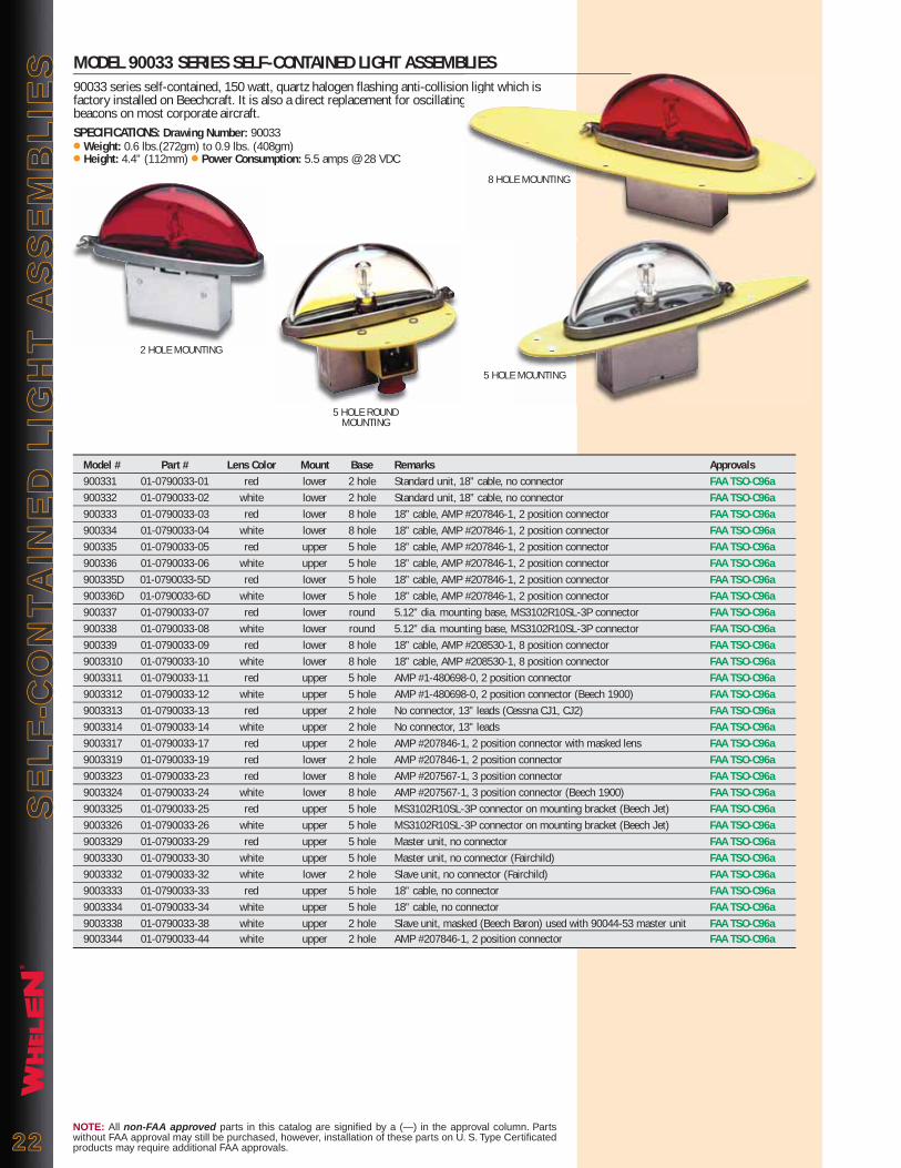
®
SE
LF
-CO
NT
AIN
ED
LIG
HT
AS
SE
MB
LIE
SS
EL
F-C
ON
TA
INE
D L
IGH
T A
SS
EM
BL
IES MODEL 90033 SERIES SELF-CONTAINED LIGHT ASSEMBLIES
90033 series self-contained, 150 watt, quartz halogen flashing anti-collision light which is factory installed on Beechcraft. It is also a direct replacement for oscillating beacons on most corporate aircraft. SPECIFICATIONS: Drawing Number: 90033 ● Weight: 0.6 lbs.(272gm) to 0.9 lbs. (408gm)● Height: 4.4” (112mm) ● Power Consumption: 5.5 amps @ 28 VDC
NOTE: All non-FAA approved parts in this catalog are signified by a (—) in the approval column. Parts without FAA approval may still be purchased, however, installation of these parts on U. S. Type Certificated products may require additional FAA approvals.2222
n light which is
5 HOLE MOUNTING
2 HOLE MOUNTING
Model # Part # Lens Color Mount Base Remarks Approvals 900331 01-0790033-01 red lower 2 hole Standard unit, 18” cable, no connector FAA TSO-C96a 900332 01-0790033-02 white lower 2 hole Standard unit, 18” cable, no connector FAA TSO-C96a 900333 01-0790033-03 red lower 8 hole 18” cable, AMP #207846-1, 2 position connector FAA TSO-C96a 900334 01-0790033-04 white lower 8 hole 18” cable, AMP #207846-1, 2 position connector FAA TSO-C96a 900335 01-0790033-05 red upper 5 hole 18” cable, AMP #207846-1, 2 position connector FAA TSO-C96a 900336 01-0790033-06 white upper 5 hole 18” cable, AMP #207846-1, 2 position connector FAA TSO-C96a 900335D 01-0790033-5D red lower 5 hole 18” cable, AMP #207846-1, 2 position connector FAA TSO-C96a 900336D 01-0790033-6D white lower 5 hole 18” cable, AMP #207846-1, 2 position connector FAA TSO-C96a 900337 01-0790033-07 red lower round 5.12” dia. mounting base, MS3102R10SL-3P connector FAA TSO-C96a 900338 01-0790033-08 white lower round 5.12” dia. mounting base, MS3102R10SL-3P connector FAA TSO-C96a 900339 01-0790033-09 red lower 8 hole 18” cable, AMP #208530-1, 8 position connector FAA TSO-C96a 9003310 01-0790033-10 white lower 8 hole 18” cable, AMP #208530-1, 8 position connector FAA TSO-C96a 9003311 01-0790033-11 red upper 5 hole AMP #1-480698-0, 2 position connector FAA TSO-C96a 9003312 01-0790033-12 white upper 5 hole AMP #1-480698-0, 2 position connector (Beech 1900) FAA TSO-C96a 9003313 01-0790033-13 red upper 2 hole No connector, 13” leads (Cessna CJ1, CJ2) FAA TSO-C96a 9003314 01-0790033-14 white upper 2 hole No connector, 13” leads FAA TSO-C96a 9003317 01-0790033-17 red upper 2 hole AMP #207846-1, 2 position connector with masked lens FAA TSO-C96a 9003319 01-0790033-19 red lower 2 hole AMP #207846-1, 2 position connector FAA TSO-C96a 9003323 01-0790033-23 red lower 8 hole AMP #207567-1, 3 position connector FAA TSO-C96a 9003324 01-0790033-24 white lower 8 hole AMP #207567-1, 3 position connector (Beech 1900) FAA TSO-C96a 9003325 01-0790033-25 red upper 5 hole MS3102R10SL-3P connector on mounting bracket (Beech Jet) FAA TSO-C96a 9003326 01-0790033-26 white upper 5 hole MS3102R10SL-3P connector on mounting bracket (Beech Jet) FAA TSO-C96a 9003329 01-0790033-29 red upper 5 hole Master unit, no connector FAA TSO-C96a 9003330 01-0790033-30 white upper 5 hole Master unit, no connector (Fairchild) FAA TSO-C96a 9003332 01-0790033-32 white lower 2 hole Slave unit, no connector (Fairchild) FAA TSO-C96a 9003333 01-0790033-33 red upper 5 hole 18” cable, no connector FAA TSO-C96a 9003334 01-0790033-34 white upper 5 hole 18” cable, no connector FAA TSO-C96a 9003338 01-0790033-38 white upper 2 hole Slave unit, masked (Beech Baron) used with 90044-53 master unit FAA TSO-C96a 9003344 01-0790033-44 white upper 2 hole AMP #207846-1, 2 position connector FAA TSO-C96a
8 HOLE MOUNTING
5 HOLE ROUNDMOUNTING

®
PO
SIT
ION
LIG
HT
AS
SE
MB
LIE
SP
OS
ITIO
N L
IGH
T A
SS
EM
BL
IES
MODEL 70963 SERIES LED FORWARD POSITION LIGHTS70963 series is designed to replace existing incandescent & halogen position lights used on most business and commuter jets. The benefits of LED technology will drastically reduce operating costs and improve reliability over the existing lighting. The 70963 series are war-ranted to comply with FAA color & light output regulations for 5 years or 10,000 hours.SPECIFICATIONS: ● Power Consumption: 0.3 amps @ 28 VDC ● Weight: 0.25 lbs. (113gm)● Input Voltage: 22-30 VDC ● LED Color: Aviation Red, Aviation Green ● Exposed Height: 1.98" (50mm) ● Diameter: 2.10" (53mm)Model # Part # Description Approvals7096303 01-0770963-03 Green position light FAA TSO-C30c Type II7096304 01-0770963-04 Red position light FAA TSO-C30c Type I
MODEL 71105 SERIES LED POSITION LIGHT ASSEMBLY71105 series are fully FAA TSO compliant forward position lights. LED's provide a significant reduction in electrical current draw over conventional light bulbs. The 71105 is our latest design and lowest priced forward position light. Direct replacement for Whelen Model W1285 series (Version STC'd on Learjet Aircraft).SPECIFICATIONS: ● LED Navigation Light Power Consumption: 0.25 amps @ 14 VDC or 28 VDC● LED Colors: Aviation Red, Aviation Green ● Weight: 0.20 lbs. (91gm) 14 VDC, 0.25 lbs. (113gm) 28 VDC ● Exposed Height: 2.70” (69mm) ● Lens: Clear Polycarbonate Model # Part # Description Approvals7110501 01-0771105-01 Position green, 14 VDC FAA TSO-C30c Type II7110502 01-0771105-02 Position red, 14 VDC FAA TSO-C30c Type I7110503 01-0771105-03 Position green, 28 VDC FAA TSO-C30c Type II7110504 01-0771105-04 Position red, 28 VDC FAA TSO-C30c Type I
MODEL W1285 SERIESW1285 series wing tip position light which uses a 26-watt incandescent lamp. It is a direct replacement for the brand “G” A1285 series. Specify 14 or 28 VDC.SPECIFICATIONS: ● Drawing Number: 70001 ● Weight: 0.2 lbs. (91gm) ● Height: 1.25” (32mm)● Length: 4” (102mm) ● Power Consumption: 2 amps @ 14 VDC, 1 amp @ 28 VDCModel # Part # Description ApprovalsW1285PG1 01-0770001-41 14 VDC, position green FAA TSO-C30b Type IIW1285PR1 01-0770001-51 14 VDC, position red FAA TSO-C30b Type IW1285PG2 01-0770001-42 28 VDC, position green FAA TSO-C30b Type IIW1285PR2 01-0770001-52 28 VDC, position red FAA TSO-C30b Type I
MODEL 71015 SERIES LED FORWARD POSITION LIGHTS71015 series are FAA TSO compliant forward position lights. They are compatible with the Whelen W1250 position light mounting as well as any other make that uses the same mount-ing pattern.SPECIFICATIONS: ● Power Consumption: 0.3 amps @ 28 VDC● LED Color: Aviation Red; and Aviation Green ● Weight: 0.2 lbs. (91gm) ● Exposed Height: 1.33" (34mm) ● Length: 2.41" (61mm)Model # Part # Description Approvals7101501 01-0771015-01 Green position light, 28 VDC FAA TSO-C30c Type II7101502 01-0771015-02 Red position light, 28 VDC FAA TSO-C30c Type I
NOTE: All non-FAA approved parts in this catalog are signified by a (—) in the approval column. Parts without FAA approval may still be purchased, however, installation of these parts on U. S. Type Certificated products may require additional FAA approvals. 2323
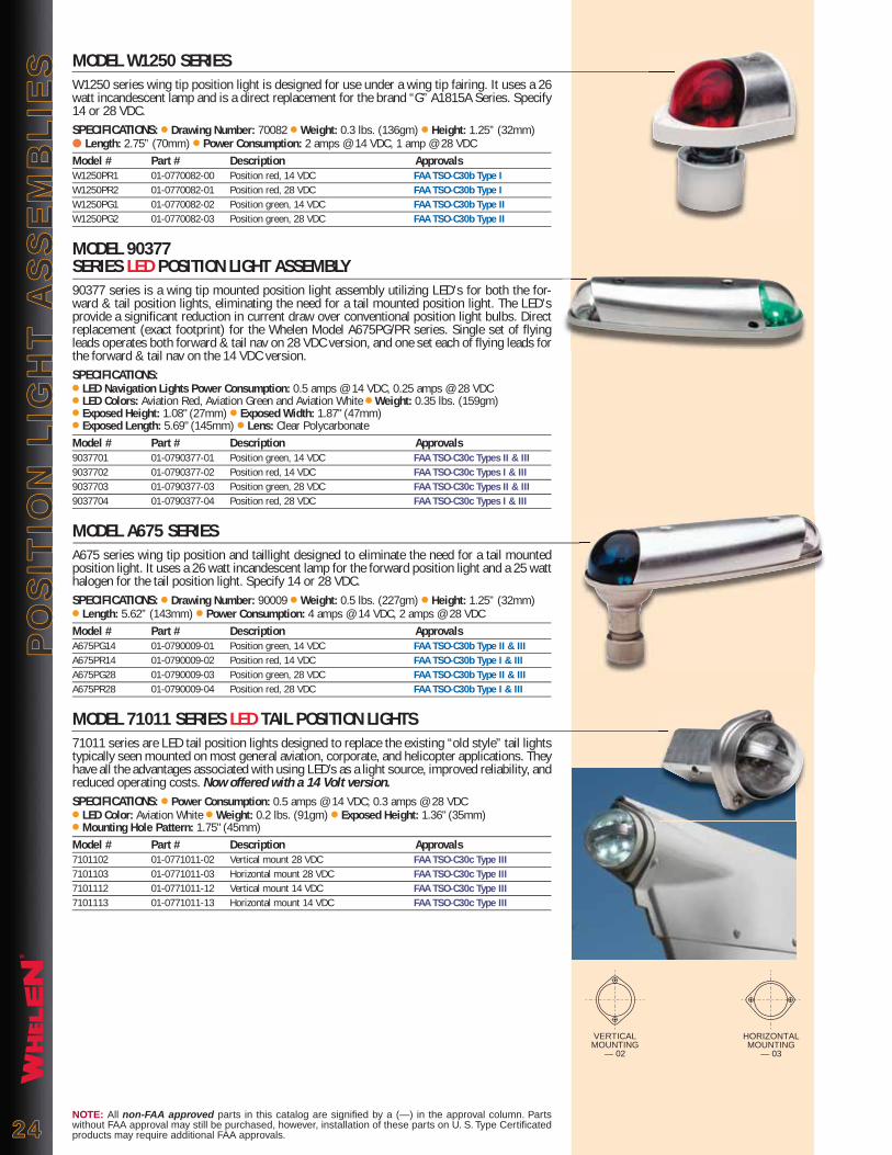
®
PO
SIT
ION
LIG
HT
AS
SE
MB
LIE
SP
OS
ITIO
N L
IGH
T A
SS
EM
BL
IES
NOTE: All non-FAA approved parts in this catalog are signified by a (—) in the approval column. Parts without FAA approval may still be purchased, however, installation of these parts on U. S. Type Certificated products may require additional FAA approvals.2424
MODEL W1250 SERIESW1250 series wing tip position light is designed for use under a wing tip fairing. It uses a 26 watt incandescent lamp and is a direct replacement for the brand “G” A1815A Series. Specify 14 or 28 VDC.SPECIFICATIONS: ● Drawing Number: 70082 ● Weight: 0.3 lbs. (136gm) ● Height: 1.25” (32mm)● Length: 2.75” (70mm) ● Power Consumption: 2 amps @ 14 VDC, 1 amp @ 28 VDCModel # Part # Description ApprovalsW1250PR1 01-0770082-00 Position red, 14 VDC FAA TSO-C30b Type IW1250PR2 01-0770082-01 Position red, 28 VDC FAA TSO-C30b Type IW1250PG1 01-0770082-02 Position green, 14 VDC FAA TSO-C30b Type IIW1250PG2 01-0770082-03 Position green, 28 VDC FAA TSO-C30b Type II
MODEL 90377SERIES LED POSITION LIGHT ASSEMBLY90377 series is a wing tip mounted position light assembly utilizing LED's for both the for-ward & tail position lights, eliminating the need for a tail mounted position light. The LED's provide a significant reduction in current draw over conventional position light bulbs. Direct replacement (exact footprint) for the Whelen Model A675PG/PR series. Single set of flying leads operates both forward & tail nav on 28 VDC version, and one set each of flying leads for the forward & tail nav on the 14 VDC version.SPECIFICATIONS:● LED Navigation Lights Power Consumption: 0.5 amps @ 14 VDC, 0.25 amps @ 28 VDC● LED Colors: Aviation Red, Aviation Green and Aviation White ● Weight: 0.35 lbs. (159gm)● Exposed Height: 1.08" (27mm) ● Exposed Width: 1.87" (47mm) ● Exposed Length: 5.69" (145mm) ● Lens: Clear Polycarbonate Model # Part # Description Approvals9037701 01-0790377-01 Position green, 14 VDC FAA TSO-C30c Types II & III9037702 01-0790377-02 Position red, 14 VDC FAA TSO-C30c Types I & III9037703 01-0790377-03 Position green, 28 VDC FAA TSO-C30c Types II & III9037704 01-0790377-04 Position red, 28 VDC FAA TSO-C30c Types I & III
MODEL A675 SERIESA675 series wing tip position and taillight designed to eliminate the need for a tail mounted position light. It uses a 26 watt incandescent lamp for the forward position light and a 25 watt halogen for the tail position light. Specify 14 or 28 VDC.SPECIFICATIONS: ● Drawing Number: 90009 ● Weight: 0.5 lbs. (227gm) ● Height: 1.25” (32mm)● Length: 5.62” (143mm) ● Power Consumption: 4 amps @ 14 VDC, 2 amps @ 28 VDCModel # Part # Description ApprovalsA675PG14 01-0790009-01 Position green, 14 VDC FAA TSO-C30b Type II & IIIA675PR14 01-0790009-02 Position red, 14 VDC FAA TSO-C30b Type I & IIIA675PG28 01-0790009-03 Position green, 28 VDC FAA TSO-C30b Type II & IIIA675PR28 01-0790009-04 Position red, 28 VDC FAA TSO-C30b Type I & III
MODEL 71011 SERIES LED TAIL POSITION LIGHTS71011 series are LED tail position lights designed to replace the existing “old style” tail lights typically seen mounted on most general aviation, corporate, and helicopter applications. They have all the advantages associated with using LED’s as a light source, improved reliability, and reduced operating costs. Now offered with a 14 Volt version.SPECIFICATIONS: ● Power Consumption: 0.5 amps @ 14 VDC; 0.3 amps @ 28 VDC● LED Color: Aviation White ● Weight: 0.2 lbs. (91gm) ● Exposed Height: 1.36" (35mm)● Mounting Hole Pattern: 1.75" (45mm)Model # Part # Description Approvals7101102 01-0771011-02 Vertical mount 28 VDC FAA TSO-C30c Type III7101103 01-0771011-03 Horizontal mount 28 VDC FAA TSO-C30c Type III7101112 01-0771011-12 Vertical mount 14 VDC FAA TSO-C30c Type III7101113 01-0771011-13 Horizontal mount 14 VDC FAA TSO-C30c Type III
HORIZONTALMOUNTING
— 03
VERTICALMOUNTING
— 02
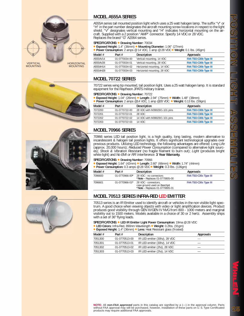
®
PO
SIT
ION
LIG
HT
AS
SE
MB
LIE
SP
OS
ITIO
N L
IGH
T A
SS
EM
BL
IES
NOTE: All non-FAA approved parts in this catalog are signified by a (—) in the approval column. Parts without FAA approval may still be purchased, however, installation of these parts on U. S. Type Certificated products may require additional FAA approvals. 2525
MODEL A555A SERIESA555A series tail mounted position light which uses a 25 watt halogen lamp. The suffix “V” or “H” in the part number designates the aircraft mounting screw locations in respect to the light shield. “V” designates vertical mounting and “H” indicates horizontal mounting on the air-craft. Supplied with a 2 position “AMP” connector. Specify 14 VDC or 28 VDC. Replaces the brand “G” A2064 series.SPECIFICATIONS: ● Drawing Number: 70034 ● Exposed Height: 1.4” (36mm) ● Mounting Diameter: 1.06” (27mm)● Power Consumption: 2 amps @ 14 VDC, 1 amp @ 28 VDC ● Weight: 0.1 lbs. (45gm) Model # Part # Description ApprovalsA555AV14 01-0770034-00 Vertical mounting, 14 VDC FAA TSO-C30b Type IIIA555AV28 01-0770034-01 Vertical mounting, 28 VDC FAA TSO-C30b Type IIIA555AH14 01-0770034-02 Horizontal mounting, 14 VDC FAA TSO-C30b Type IIIA555AH28 01-0770034-03 Horizontal mounting, 28 VDC FAA TSO-C30b Type III
MODEL 70722 SERIES70722 series wing tip mounted, tail position light. Uses a 25 watt halogen lamp. It is standard equipment for the Raytheon JPATS military trainer.SPECIFICATIONS: ● Drawing Number: 70722● Exposed Height: 1.04” (26mm) ● Length: 2.94” (75mm) ● Width: 1.48” (38mm)● Power Consumption: 2 amps @14 VDC, 1 amp @28 VDC ● Weight: 0.13 lbs. (59gm) Model # Part # Description Approvals7072200 01-0770722-00 28 VDC with M39029/1-101 pins FAA TSO-C30b Type III7072201 01-0770722-01 28 VDC FAA TSO-C30b Type III7072202 01-0770722-02 14 VDC with M39029/1-101 pins FAA TSO-C30b Type III7072203 01-0770722-03 14 VDC FAA TSO-C30b Type III
MODEL 70966 SERIES70966 series LED tail position light, is a high quality, long lasting, modern alternative to incandescent & halogen tail position lights. It offers significant technological upgrades over previous products. Utilizing LED technology, the following advantages are offered: Long Life (approx. 20,000 hours); Reduced Power Consumption (compared to alternative light sourc-es); Shock & Vibration Resistant (no fragile filament to burn out); Light (produces bright white light) and No EMI or RFI Interference. 3 Year Warranty.SPECIFICATIONS: ● Drawing Number: 70966● Exposed Height: 1.64” (42mm) ● Length: 2.60” (66mm) ● Width: 1.74” (44mm) ● Power Consumption: 0.3 amps @ 28 VDC ● Weight: 0.3 lbs. (136gm)Model # Part # Description Approvals7096600 01-0770966-00* 28 VDC - no connectors FAA TSO-C30c Type III *Note - Replaces 01-0770805-00 7096601 01-0770966-01* 28 VDC - connectors, FAA TSO-C30c Type III case ground used on Beechjet *Note - Replaces 01-0770805-01
MODEL 70513 SERIES INFRA-RED LED EMITTER70513 series is an IR Emitter used to identify aircraft or vehicles in the non visible light spec-trum. A good choice when viewing objects with video or light amplification devices. Product produces good visibility through GEN III/GEN IV NVG from 800 - 1000 meters and marginal visibility out to 1500 meters. Models available in a choice of 30 or 2 hertz. Assembly ships with a set of 36" flying leads.SPECIFICATIONS: ● LED IR Emitter Light Power Consumption: 19ma @ 28 VDC● LED Colors: Infra-Red, 890nm Wavelength ● Weight: 0.2lbs. (91gm) ● Exposed Height: 1.4" (36mm) ● Lens: Heat Resistant glass (frosted)Model # Part # Description Approvals7051300 01-0770513-00 IR LED emitter (30hz), 28 VDC —7051301 01-0770513-01 IR LED emitter (30hz), 14 VDC —7051302 01-0770513-02 IR LED emitter (2hz), 28 VDC —7051303 01-0770513-03 IR LED emitter (2hz), 14 VDC —
VERTICAL MOUNTING
HORIZONTAL MOUNTING

®
INT
ER
IOR
LIG
HT
ING
INT
ER
IOR
LIG
HT
ING
NOTE: All non-FAA approved parts in this catalog are signified by a (—) in the approval column. Parts without FAA approval may still be purchased, however, installation of these parts on U. S. Type Certificated products may require additional FAA approvals.2626
MODEL 70844 SERIES70844 series are LED (Light Emitting Diode) instrument post light assemblies. They are designed to illuminate the instrument panel and function as instrument mounting bolts. It is a high quality, long lasting, modern alternative to standard incandescent post lights. They offer significant technological upgrades over existing products. Utilizing LED technology, the fol-lowing advantages are offered: Long Life (approx. 20,000 hours); Reduced Power Consumption (compared to alternative light sources); Shock & Vibration Resistant (no fragile filament to burn out); Light (produces bright white light) and No EMI or RFI Interference.SPECIFICATIONS: ● Drawing Number: 70844 ● Weight: 0.03 lbs. (14gm)● Exposed Height: 1.00" (25mm) without spacer, 1.12" (28mm) w/spacer● Power Consumption: 0.02 amps @ 14 VDC, and 0.02 amps @ 28 VDCModel # Part # Description Approvals7084400 01-0770844-00 1.00" post, 14 VDC —7084401 01-0770844-01 1.50" post, 14 VDC —7084402 01-0770844-02 1.00" post, 28 VDC —7084403 01-0770844-03 1.50" post, 28 VDC —
MODEL A350 & A350CN SERIESA350 and A350CN series instrument post light assemblies are designed to illuminate the instrument panel and function as instrument mounting bolts. The A350 is identical to the A350CN, but without the connector nut.SPECIFICATIONS: ● Drawing Number A350: 70116 ● Drawing Number A350CN: 70119● Exposed Height: .875” (22mm) without spacer, 1.00” (25mm) with spacer ● Power Consumption: 0.2 amps @6 VDC, 0.08 amps @14 VDC, & 0.04 amps @ 28 VDC● Weight: 0.037 lbs. (17gm) Model # Part # Description ApprovalsA350 01-0770116-( ) Instrument post light assemblies —A350CN 01-0770119-( ) Instrument post light assemblies FAA/PMA-( )
ORDERING OPTIONS:Lens Colors Post Colors Post Heights VoltagesIW = Instrument White BK = Black SH = Short (1.875”) 6 = (328 lamp)CL = Clear GR = Grey LG = Long (2.375”) 14 = (330 lamp)RD = Red 28 = (327 lamp)
Ordering Code Example: A350CN - BK - CL - SH - 14
MODEL 70348 SERIES70348 series instrument post light assemblies is designed to illuminate the instrument panel and function as instrument mounting bolts. The unit has a #10-32 mounting thread and uses the #327 lamp. 28 VDC Only.SPECIFICATIONS: ● Drawing Number: 70348 ● Weight: 0.037 lbs. (17gm)● Exposed Height: 0.856” (22mm) ● Power Consumption: 0.04 amps @ 28 VDCModel # Part # Description Approvals7034800 01-0770348-00 Instrument white, 28 VDC —7034801 01-0770348-01 Red w/spacer, 28 VDC —7034802 01-0770348-02 Clear, 28 VDC —7034803 01-0770348-03 Red, 28 VDC —
MODEL C70190 SERIESC70190 series Interior gooseneck light assembly featuring a positive off position & rheostat controlled light intensity. Uses the #1495 lamp. 28 VDC Only.SPECIFICATIONS: ● Drawing Number: 70190 ● Weight: 0.3 lbs. (136gm) ● Lamp: 6 watt ● Power Consumption: 0.3 amps @ 28 VDCModel # Part # Description Approvals70190( ) 01-0770190( ) As requested (see chart) FAA/PMA (12” Only)
Ordering Code Example: 70190 - B - 12
Model P/N Lens Color Arm Length in inches70190 W = Clear 04 = 4”, 06 = 6”, 08 = 8”, R = Red 10 = 10”, 12 = 12”, 14 = 14”, 16 = 16”, 18 = 18”, B = Blue (Inst. White) 20 = 20”, 22 = 22”, 24 = 24”
Assy P/N Post Color Post Height VoltageLens Color
A350
A350CN
70348
70844

®
INT
ER
IOR
LIG
HT
ING
INT
ER
IOR
LIG
HT
ING
NOTE: All non-FAA approved parts in this catalog are signified by a (—) in the approval column. Parts without FAA approval may still be purchased, however, installation of these parts on U. S. Type Certificated products may require additional FAA approvals. 2727
MODEL 71144 'GOOSENECK' LED LIGHT ASSEMBLY 71144 assembly features a positive off position and rheostat controlled light intensity. Models including 'side' mounted intensity control are which is designed for the S76D. 28 VDC Only.SPECIFICATIONS: ● Power Consumption: 0.06 amps @ 28 VDC ● LED Colors: Aviation White ● Weight: 0.46 lbs. (209gm) ● Black Nylon Hood: fixed in positionModel # Part # Description Approvals7114416 01-0771144-16 16 inch adjustable map light, 28 VDC —
MODEL 70820 SERIES INTERIOR LED MAP/READING LIGHT70820 series are LED (Light Emitting Diode) interior map/reading light assemblies. They are designed for cabin, or cockpit illumination. It has a 360º swivel base, allowing for infinite light angle adjustment. Utilizing LED technology, the following advantages are offered: Long Life (approx. 20,000 hours); Reduced Power Consumption (compared to alternative light sources) and Shock & Vibration Resistant.
SPECIFICATIONS: ● Drawing Number: 70820 ● Weight: 0.19 lbs. (86gm)● Power Consumption: 0.02 amps @ 14 VDC, 0.02 amps @ 28 VDCModel # Part # Description Approvals7082000 01-0770820-00 White LED, natural aluminum finish, 14 VDC —7082001 01-0770820-01 White LED, natural aluminum finish, 28 VDC —7082002 01-0770820-02 White LED, black anodized finish, 14 VDC —7082003 01-0770820-03 White LED, black anodized finish, 28 VDC —7082004 01-0770820-04 Red LED, black anodized finish, 14 VDC —7082005 01-0770820-05 Red LED, black anodized finish, 28 VDC —7082006 01-0770820-06 Blue LED, black anodized finish, 14 VDC —7082007 01-0770820-07 Blue LED, black anodized finish, 28 VDC —
MODEL 71140 SERIES LED DOME LIGHT, PRIMARY & EMERGENCY LIGHTING71140 series is an LED alternative to Grimes 34170 (dome light) used on Bombardier Global Express, Challenger 600, 601, 604; Gulfstream GIII, GIV; Learjet 54, 56, 60 and Sikorsky S76. Primary operating voltage is 28 VDC, an emergency circuit at 5 VDC is provided for long-life lighting on an alternate power source. Spun aluminum assembly 5.5 inches outer diameter, 3.83 inch recessed inner diameter with a 1 inch recessed depth. Item ships with three flying leads, a ground, a 5 VDC line and a 28 VDC line.SPECIFICATIONS: ● Power Consumption: 125mA @ 28 VDC, 250mA @ 5 VDC● LED Color: Aviation White ● Weight: 0.35 lbs. (159m) ● Exposed Height: 0.45 (11mm)● Lens: Translucent Polycarbonate Model # Part # Description Approvals7114000 01-0771140-00 LED interior dome light —
MODEL A300 SERIESA300 series interior map light assemblies designed for indirect cockpit illumination. Slide switch permits direct chart reading. Available with a red or instrument white lens. Uses a 14 VDC #1414 lamp or a 28 VDC #1495 lamp.SPECIFICATIONS: ● Drawing Number: 70104 ● Depth Behind Mounting Flange: 1.06” (27mm) ● Weight: 0.16 lbs. (73gm) ● Lamp Wattage: 6 watts ● Power Consumption: 0.46 amps @ 14 VDC, 0.3 amps @ 28 VDCModel # Part # Description ApprovalsA300W14 01-0770104-30 Instrument white, 14 VDC —A300W28 01-0770104-31 Instrument white, 28 VDC —A300R14 01-0770104-50 Red, 14 VDC —A300R28 01-0770104-51 Red, 14 VDC —
MODEL 70339 SERIES70339 series interior dome/compartment light assemblies designed for recessed overhead or wall mounting with minimal depth. An On/Off switch is optional. Uses a 14 VDC #1414 lamp or a 28 VDC #1495 lamp.SPECIFICATIONS: ● Drawing Number: 70339● Depth Behind Mounting Flange: 1.06” (27mm) ● Weight: 0.16 lbs. (73gm)● Lamp Wattage: 6 watts ● Power Consumption: 0.46 amps @ 14 VDC, 0.3 amps @ 28 VDCModel # Part # Description Approvals7033901 01-0770339-01 14 VDC —7033902 01-0770339-02 28 VDC —7033903 01-0770339-03 14 VDC with switch —7033904 01-0770339-04 28 VDC with switch —
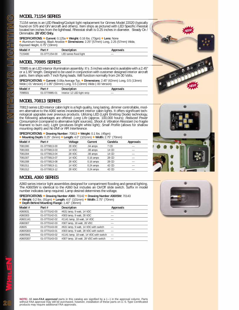
®
INT
ER
IOR
LIG
HT
ING
INT
ER
IOR
LIG
HT
ING
2828NOTE: All non-FAA approved parts in this catalog are signified by a (—) in the approval column. Parts without FAA approval may still be purchased, however, installation of these parts on U. S. Type Certificated products may require additional FAA approvals.
MODEL 71154 SERIES71154 series is an LED Reading/Cockpit light replacement for Grimes Model 22020 (typically found on S76 and GIV aircraft and others). Item ships as pictured with LED Specific rheostat located ten inches from the lighthead. Rheostat shaft is 0.25 inches in diameter. Steady On / Dimmable. 28 VDC Only.SPECIFICATIONS: ● Current: 0.125a ● Weight: 0.16 lbs. (73gm) ● Lens: None ● Aluminum housing, Black Anodize ● Dimensions: 2.25" (57mm) Long, 2.25 (57mm) Wide, Exposed Height, 0.75" (19mm)
Model # Part # Description Approvals7115400 01-0771154-00 LED series flood light —
MODEL 70985 SERIES70985 is an LED interior illumination assembly. It's .5 inches wide and is available with a 2.45" or a 1.95" length. Designed to be used in conjunction with customer designed interior aircraft parts. Item ships with 7 inch flying leads. Will function normally from 24-30 Volts. SPECIFICATIONS: ● Current: 0.06a Average Typ. ● Dimensions: 2.45" (62mm) Long, 0.5 (13mm) Wide (-01 Version) // 1.95" (50mm) Long, 0.5 (13mm) Wide (-00 Version)
Model # Part # Description Approvals7098501 01-0770985-01 Interior 12 LED light strip —
MODEL 70813 SERIES70813 series LED interior cabin light is a high quality, long lasting, dimmer controllable, mod-ern alternative to the A360 series incandescent interior cabin lights. It offers significant tech-nological upgrades over previous products. Utilizing LED (Light Emitting Diode) technology, the following advantages are offered: Long Life (approx. 100,000 hours); Reduced Power Consumption (compared to alternative light sources); Shock & Vibration Resistant (no fragile filament to burn out); Light (produces bright white light); Small Profile (allows for shallow mounting depth) and No EMI or RFI Interference.SPECIFICATIONS: ● Drawing Number: 70813 ● Weight: 0.1 lbs. (45gm) ● Mounting Depth: 0.25” (6mm) ● Length: 4.0” (101mm) ● Width: 2.75” (70mm)Model # Part # Voltage Current Candela Approvals7081300 01-0770813-00 28 VDC .04 amps 7 CD —7081303 01-0770813-03 14 VDC .08 amps 14 CD —7081304 01-0770813-04 28 VDC .08 amps 14 CD —7081307 01-0770813-07 14 VDC 0.16 amps 28 CD —7081308 01-0770813-08 28 VDC 0.16 amps 28 CD —7081311 01-0770813-11 14 VDC 0.24 amps 42 CD —7081312 01-0770813-12 28 VDC 0.24 amps 42 CD —
MODEL A360 SERIESA360 series interior light assemblies designed for compartment flooding and general lighting. The A360SW is identical to the A360 but includes an On/Off slide switch. Suffix in model number indicates lamp required. Lamp desired determines the voltage.SPECIFICATIONS: ● Drawing Number A360: 70142 ● Drawing Number A360SW: 70143● Weight: 0.2 lbs. (91gm) ● Length: 4.0” (101mm) ● Width: 2.75” (70mm) ● Depth Behind Mounting Flange: 1.40” (36mm)Model # Part # Description ApprovalsA360631 01-0770142-00 #631 lamp, 9 watt, 14 VDC —A360303 01-0770142-01 #303 lamp, 9 watt, 28 VDC —A3601141 01-0770142-02 #1141 lamp, 18 watt, 14 VDC —A360307 01-0770142-03 #307 lamp, 18 watt, 28 VDC —A360S 01-0770143-00 #631 lamp, 9 watt, 14 VDC with switch —A360S303 01-0770143-01 #303 lamp, 9 watt, 28 VDC with switch —A360SW1 01-0770143-02 #1141 lamp, 18 watt, 14 VDC with switch —A360S307 01-0770143-03 #307 lamp, 18 watt, 28 VDC with switch —
NEW!
NEW!

®
INT
ER
IOR
LIG
HT
ING
INT
ER
IOR
LIG
HT
ING
2929NOTE: All non-FAA approved parts in this catalog are signified by a (—) in the approval column. Parts without FAA approval may still be purchased, however, installation of these parts on U. S. Type Certificated products may require additional FAA approvals.
MODEL A315-HI SERIESA315-HI series cockpit utility light assembly which rotates for convenience in reading maps and illuminating instrument panels. Furnished with a right angle bracket for ease of mounting. Available with instrument white (blue) lens, red or clear. Uses a 14 VDC #1414 or a 28 VDC #1495 lamp.SPECIFICATIONS: ● Drawing Number: 70113● Weight: 0.07 lbs. (32gm) ● Height: 2.2” (56mm) ● Depth: 0.93” (24mm) ● Width: 0.87” (22mm)● Power Consumption: 0.46 amps @ 14 VDC, 0.3 amps @ 28 VDCModel # Part # Description ApprovalsA315HIR1 01-0770113-00 Red lens, 14 VDC —A315HIR2 01-0770113-01 Red lens, 28 VDC —A315HIW1 01-0770113-02 White lens, 14 VDC —A315HIW2 01-0770113-03 White lens, 28 VDC —A315HIB1 01-0770113-04 Instrument white lens, 14 VDC —A315HIB2 01-0770113-05 Instrument white lens, 28 VDC —
MODEL A315-LO SERIESA315-LO series cockpit utility light assembly which rotates for convenience in reading maps and illuminating instrument panels. Optional right angle bracket available for ease of mount-ing. Uses a 14 VDC #1893 or a 28 VDC #1864 lamp.SPECIFICATIONS: ● Drawing Number: 70106● Weight: 0.06 lbs. (27gm) ● Height: 2.18” (55mm) ● Depth: 0.81” (21mm) ● Width: 0.81” (21mm) ● Power Consumption: 0.33 amps @ 14 VDC, 0.17 amps @ 28 VDCModel # Part # Description ApprovalsA315LO14 01-0770106-00 14 VDC —A315LO28 01-0770106-01 28 VDC —
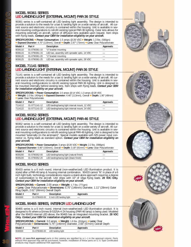
®
EX
TE
RIO
R L
IGH
TIN
GE
XT
ER
IOR
LIG
HT
ING
3030NOTE: All non-FAA approved parts in this catalog are signified by a (—) in the approval column. Parts without FAA approval may still be purchased, however, installation of these parts on U. S. Type Certificated products may require additional FAA approvals.
MODEL 90361 SERIES LED LANDING LIGHT (EXTERNAL MOUNT) PAR-36 STYLE90361 series is a self-contained all LED landing light assembly. The design is intended to provide a solution to the needs for a taxi & landing light on a wide variety of aircraft. All cur-rent source and electronic circuitry is contained within the housing. Unit is available in sev-eral mounting configurations to retrofit existing typical PAR-36 lighting. Outer lens allows for mounting externally on aircraft, option of diffusion lens available upon request. Item ships with flying leads. Contact your OEM for installation eligibility on your aircraft.SPECIFICATIONS: ● Power Consumption: 1.5 amps @ 28 VDC ● Weight: 1.3 lbs. (590gm)● Exposed Diameter: 4.70" (119mm), Overall ● Depth: 2.87" (73mm) ● Lens: Clear PolycarbonateModel # Part # Description Approvals9036110 01-0790361-10 "U" bracket mounting —9036115 01-0790361-15 LED taxi, assembly with spreader optic, 14 VDC —9036120 01-0790361-20 "U" bracket mounting —9036125 01-0790361-25 LED taxi, assembly with spreader optic, 28 VDC —
MODEL 71141 SERIES LED LANDING LIGHT (INTERNAL MOUNT) PAR-36 STYLE71141 series is a self-contained all LED landing light assembly. The design is intended to provide a solution to the needs for a taxi & landing light on a wide variety of aircraft. All cur-rent source and electronic circuitry is contained within the housing. Unit is available in sev-eral mounting configurations to retrofit existing typical PAR-36 lighting. Unit is designed to be mounted internally behind existing lens. Item ships with flying leads. Contact your OEM for installation eligibility on your aircraft.SPECIFICATIONS: ● Power Consumption: 2.0 amps @ 14 VDC; 1.3 amps @ 28 VDC ● Weight: 1.0 lbs. (454gm) ● Exposed Diameter: 4.46" (113mm), Overall ● Depth: 1.90" (48mm) ● Lens: Clear Polycarbonate
Model # Part # Description Approvals7114112 01-0771141-12 LED landing/taxing light internal mount, 12 VDC —7114122 01-0771141-22 LED landing/taxing light internal mount, 24 VDC —
MODEL 90352 SERIES LED LANDING LIGHT (EXTERNAL MOUNT) PAR-46 STYLE90352 series is a self-contained all LED landing light assembly. The design is intended to provide a solution to the needs for a taxi & landing light on a wide variety of aircraft. All cur-rent source and electronic circuitry is contained within the housing. Unit is available in sev-eral mounting configurations to retrofit existing typical PAR-46 lighting. Unit is designed to be mounted "externally (in the airstream)". Special models available with MS power input con-nector vs. flying leads as standard option. Contact your OEM for installation eligibility on your aircraft.SPECIFICATIONS: ● Power Consumption: 3 amps @ 28 VDC ● Weight: 2.2 lbs. (998gm)● Exposed Diameter: 5.90" (150mm), Overall ● Depth: 3.18" (81mm) ● Lens: Clear Polycarbonate Model # Part # Description Approvals9035200 01-0790352-00 LED landing/taxing light (natural finish) —9035220 01-0790352-20 LED landing/taxing light (black finish) —
MODEL 90433 SERIES90433 series is a 6 inch round, internal (non-weatherized) LED illumination product. It is styled after a PAR-46 lamp & housing internal combination. 90433 cannot 'fit' in place of a 6 inch light bulb, technology considerations require a stand-alone approach requiring a degree of customization to the aircraft. Unit ships with 10" of 18ga flying leads. 28 VDC Only.Contact your OEM for installation eligibility on your aircraft.SPECIFICATIONS: ● Current: 2.00 amps ● Weight: 1.7 lbs. (771gm)● Lens: Clear Polycarbonate ● Dimensions: 5.75" (146mm) Diameter, 1.11" (28mm) Outer Ring Depth, 2.61" (66mm) Overall DepthModel # Part # Description Approvals9043300 01-0790433-00 6 Inch LED landing light —
MODEL 90465 SERIES, INTERIOR LED LANDING LIGHT90465 series is a 6 inch round, internal (non-weatherized) LED illumination product. It is designed to fit where a Grimes B-5325A-4-24 housing (PAR-46 lamp) is being used. Modeled after the 90433 internal LED above, the 90465 has an integrated mounting bracket. 28 VDC Only. Contact your OEM for installation eligibility on your aircraft.SPECIFICATIONS: ● Current: 3.0 amps ● Weight: 1.8 lbs. (816gm) ● Lens: Clear Polycarbonate ● Dimensions: 5.75" (146mm) Diameter, 2.65" (67mm) Overall DepthModel # Part # Description Approvals9046500 01-0790465-00 LED landing light —
NEW!
NEW!
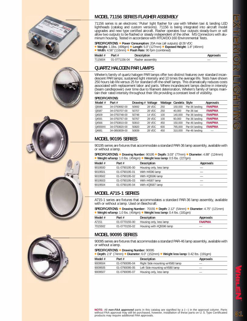
®
EX
TE
RIO
R L
IGH
TIN
GE
XT
ER
IOR
LIG
HT
ING
NOTE: All non-FAA approved parts in this catalog are signified by a (—) in the approval column. Parts without FAA approval may still be purchased, however, installation of these parts on U. S. Type Certificated products may require additional FAA approvals. 3131
MODEL 71156 SERIES FLASHER ASSEMBLY71156 series is an electronic 'Pulse' light flasher for use with Whelen taxi & landing LED lightheads (catalog and custom versions). 71156 is being integrated into aircraft model upgrades and new type certified aircraft. Flasher operates four outputs steady-burn or will allow two outputs to be flashed or steady independent of the other. MS Connectors with alu-minum housing. Tested in accordance with RTCA/DO-160 Environmental Tests.SPECIFICATIONS: ● Power Consumption: 20A max (all outputs) @ 28 VDC ● Weight: 1.1lbs. (499gm) ● Length: 5.0" (127mm) ● Exposed Height: 1.8" (46mm) ● Width: 4.56" (116mm) ● Flash Rate: 90 fpm (combined)
Model # Part # Description Approvals7115604 01-0771156-04 Flasher asssembly —
QUARTZ HALOGEN PAR LAMPSWhelen’s family of quartz halogen PAR lamps offer two distinct features over standard incan-descent PAR lamps; sustained light intensity and 10 times the average life. Tests have shown 250 hours lab life versus 25 for standard off-the-shelf lamps. This dramatically reduces costs associated with replacement labor and parts. Where incandescent lamps decline in intensity (beam candlepower) over time due to filament deterioration, Whelen’s family of lamps main-tain their rated intensity throughout their life providing a constant level of visibility.SPECIFICATIONS: Model # Part # Drawing # Voltage Wattage Candela Style Approvals Q5596 34-0750692-00 50692 28 VDC 250 150,000 Par-36 landing FAA/PMA Q5587 34-0750707-00 50707 28 VDC 250 40,000 Par-36 taxi FAA/PMA Q4509 34-0750748-00 50748 14 VDC 100 140,000 Par-36 landing FAA/PMA Q4591 34-0750767-00 50767 28 VDC 100 90,000 Par-36 landing FAA/PMA Q4566 34-0750810-00 50810 28 VDC 450 150,000 Par-46 landing FAA/PMA Q4559XX 34-0750820-00 50820 28 VDC 600 765,000 Par-64 landing FAA/PMA Q4681 34-0850839-00 50839 28 VDC 450 310,000 Par-46 landing —
MODEL 90195 SERIES90195 series are fixtures that accommodate a standard PAR-36 lamp assembly, available with or without a lamp.SPECIFICATIONS: ● Drawing Number: 90195 ● Depth: 3.03” (77mm) ● Diameter: 4.88” (124mm)● Weight w/lamp: 1.0 lbs. (454gm) ● Weight less lamp: 0.5 lbs. (227gm)Model # Part # Description Approvals9019500 01-0790195-00 Housing only, less lamp —9019501 01-0790195-01 With #4596 lamp —9019502 01-0790195-02 With #Q5596 lamp —9019503 01-0790195-03 With #4587 lamp —9019504 01-0790195-04 With #Q5587 lamp —
MODEL A715-1 SERIESA715-1 series are fixtures that accommodates a standard PAR-36 lamp assembly, available with or without a lamp. Used on Beechcraft.SPECIFICATIONS: ● Drawing Number: 70155 ● Depth: 2.12” (54mm) ● Diameter: 4.75” (121mm)● Weight w/lamp: 1.0 lbs. (454gm) ● Weight less lamp: 0.4 lbs. (181gm) Model # Part # Description ApprovalsA7151 01-0770155-00 Housing only, less lamp FAA/PMA7015502 01-0770155-02 Housing with #Q5596 lamp —
MODEL 90095 SERIES90095 series are fixtures that accommodate a standard PAR-46 lamp assembly, available with or without a lamp.SPECIFICATIONS: ● Drawing Number: 90095● Depth: 2.9” (74mm) ● Diameter: 6.0” (152mm) ● Weight less lamp: 0.42 lbs. (191gm)Model # Part # Description Approvals9009504 01-0790095-04 Right Side mounting w/4580 lamp —9009505 01-0790095-05 Left Side mounting w/4580 lamp —9009507 01-0790095-07 Housing only, less lamp —
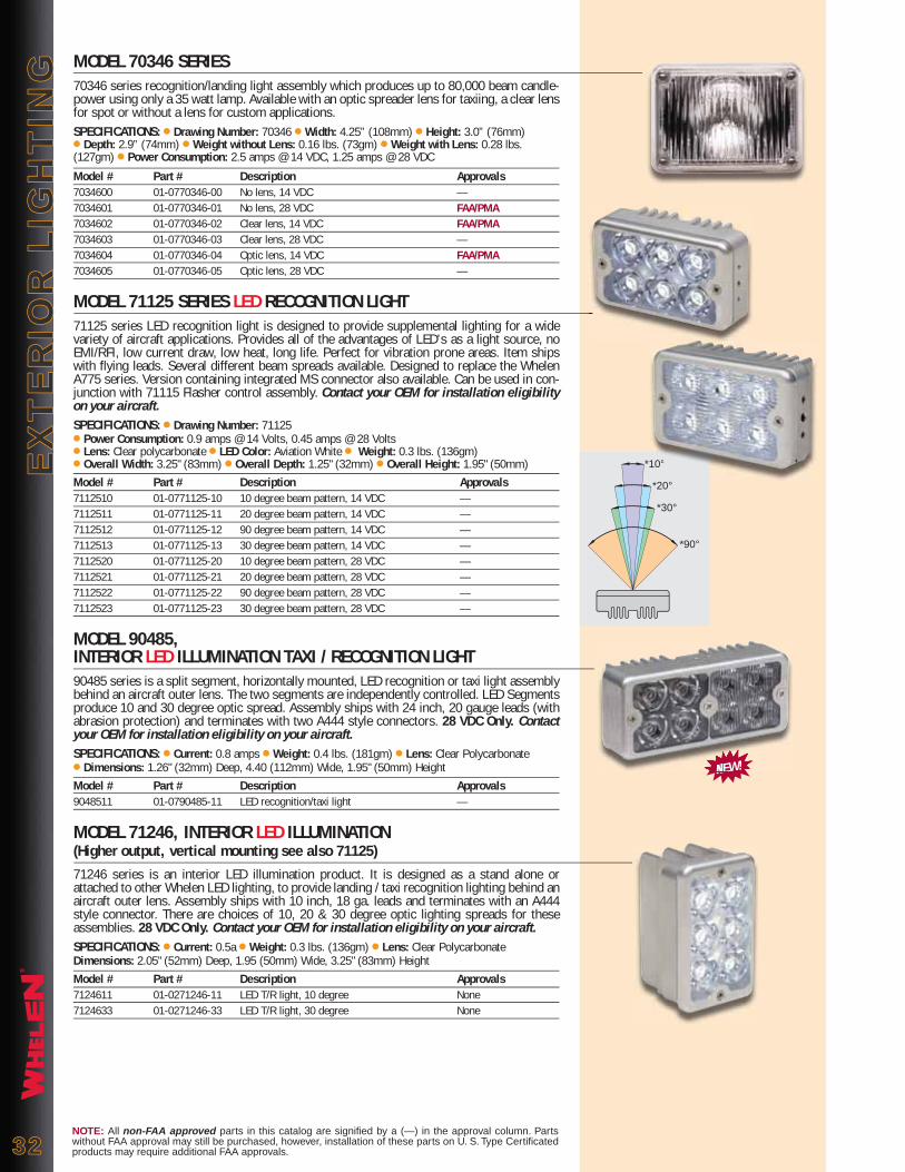
®
EX
TE
RIO
R L
IGH
TIN
GE
XT
ER
IOR
LIG
HT
ING
NOTE: All non-FAA approved parts in this catalog are signified by a (—) in the approval column. Parts without FAA approval may still be purchased, however, installation of these parts on U. S. Type Certificated products may require additional FAA approvals.3232
MODEL 70346 SERIES70346 series recognition/landing light assembly which produces up to 80,000 beam candle-power using only a 35 watt lamp. Available with an optic spreader lens for taxiing, a clear lens for spot or without a lens for custom applications.SPECIFICATIONS: ● Drawing Number: 70346 ● Width: 4.25” (108mm) ● Height: 3.0” (76mm) ● Depth: 2.9” (74mm) ● Weight without Lens: 0.16 lbs. (73gm) ● Weight with Lens: 0.28 lbs. (127gm) ● Power Consumption: 2.5 amps @ 14 VDC, 1.25 amps @ 28 VDC
Model # Part # Description Approvals7034600 01-0770346-00 No lens, 14 VDC —7034601 01-0770346-01 No lens, 28 VDC FAA/PMA7034602 01-0770346-02 Clear lens, 14 VDC FAA/PMA7034603 01-0770346-03 Clear lens, 28 VDC —7034604 01-0770346-04 Optic lens, 14 VDC FAA/PMA7034605 01-0770346-05 Optic lens, 28 VDC —
MODEL 71125 SERIES LED RECOGNITION LIGHT71125 series LED recognition light is designed to provide supplemental lighting for a wide variety of aircraft applications. Provides all of the advantages of LED's as a light source, no EMI/RFI, low current draw, low heat, long life. Perfect for vibration prone areas. Item ships with flying leads. Several different beam spreads available. Designed to replace the Whelen A775 series. Version containing integrated MS connector also available. Can be used in con-junction with 71115 Flasher control assembly. Contact your OEM for installation eligibility on your aircraft.SPECIFICATIONS: ● Drawing Number: 71125● Power Consumption: 0.9 amps @ 14 Volts, 0.45 amps @ 28 Volts ● Lens: Clear polycarbonate ● LED Color: Aviation White ● Weight: 0.3 lbs. (136gm)● Overall Width: 3.25" (83mm) ● Overall Depth: 1.25" (32mm) ● Overall Height: 1.95" (50mm)Model # Part # Description Approvals7112510 01-0771125-10 10 degree beam pattern, 14 VDC —7112511 01-0771125-11 20 degree beam pattern, 14 VDC —7112512 01-0771125-12 90 degree beam pattern, 14 VDC —7112513 01-0771125-13 30 degree beam pattern, 14 VDC —7112520 01-0771125-20 10 degree beam pattern, 28 VDC —7112521 01-0771125-21 20 degree beam pattern, 28 VDC —7112522 01-0771125-22 90 degree beam pattern, 28 VDC —7112523 01-0771125-23 30 degree beam pattern, 28 VDC —
MODEL 90485, INTERIOR LED ILLUMINATION TAXI / RECOGNITION LIGHT90485 series is a split segment, horizontally mounted, LED recognition or taxi light assembly behind an aircraft outer lens. The two segments are independently controlled. LED Segments produce 10 and 30 degree optic spread. Assembly ships with 24 inch, 20 gauge leads (with abrasion protection) and terminates with two A444 style connectors. 28 VDC Only. Contact your OEM for installation eligibility on your aircraft.SPECIFICATIONS: ● Current: 0.8 amps ● Weight: 0.4 lbs. (181gm) ● Lens: Clear Polycarbonate● Dimensions: 1.26" (32mm) Deep, 4.40 (112mm) Wide, 1.95" (50mm) HeightModel # Part # Description Approvals9048511 01-0790485-11 LED recognition/taxi light —
MODEL 71246, INTERIOR LED ILLUMINATION (Higher output, vertical mounting see also 71125)71246 series is an interior LED illumination product. It is designed as a stand alone or attached to other Whelen LED lighting, to provide landing / taxi recognition lighting behind an aircraft outer lens. Assembly ships with 10 inch, 18 ga. leads and terminates with an A444 style connector. There are choices of 10, 20 & 30 degree optic lighting spreads for these assemblies. 28 VDC Only. Contact your OEM for installation eligibility on your aircraft.SPECIFICATIONS: ● Current: 0.5a ● Weight: 0.3 lbs. (136gm) ● Lens: Clear PolycarbonateDimensions: 2.05" (52mm) Deep, 1.95 (50mm) Wide, 3.25" (83mm) HeightModel # Part # Description Approvals7124611 01-0271246-11 LED T/R light, 10 degree None7124633 01-0271246-33 LED T/R light, 30 degree None
NEW!
*90°
*30°
*20°
*10°
NEW!
10°
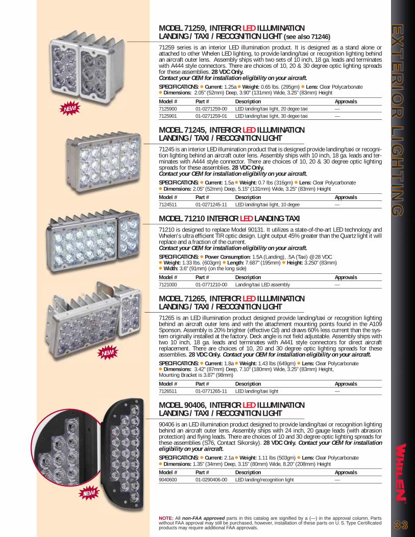
®
EX
TE
RIO
R L
IGH
TIN
GE
XT
ER
IOR
LIG
HT
ING
NOTE: All non-FAA approved parts in this catalog are signified by a (—) in the approval column. Parts without FAA approval may still be purchased, however, installation of these parts on U. S. Type Certificated products may require additional FAA approvals. 3333
MODEL 71259, INTERIOR LED ILLUMINATION LANDING / TAXI / RECOGNITION LIGHT (see also 71246)71259 series is an interior LED illumination product. It is designed as a stand alone or attached to other Whelen LED lighting, to provide landing/taxi or recognition lighting behind an aircraft outer lens. Assembly ships with two sets of 10 inch, 18 ga. leads and terminates with A444 style connectors. There are choices of 10, 20 & 30 degree optic lighting spreads for these assemblies. 28 VDC Only. Contact your OEM for installation eligibility on your aircraft.SPECIFICATIONS: ● Current: 1.25a ● Weight: 0.65 lbs. (295gm) ● Lens: Clear Polycarbonate● Dimensions: 2.05" (52mm) Deep, 3.90" (131mm) Wide, 3.25" (83mm) Height
Model # Part # Description Approvals7125900 01-0271259-00 LED landing/taxi light, 20 degee taxi —7125901 01-0271259-01 LED landing/taxi light, 30 degee taxi —
MODEL 71245, INTERIOR LED ILLUMINATION LANDING / TAXI / RECOGNITION LIGHT71245 is an interior LED illumination product that is designed provide landing/taxi or recogni-tion lighting behind an aircraft outer lens. Assembly ships with 10 inch, 18 ga. leads and ter-minates with A444 style connector. There are choices of 10, 20 & 30 degree optic lighting spreads for these assemblies. 28 VDC Only.Contact your OEM for installation eligibility on your aircraft.SPECIFICATIONS: ● Current: 1.5a ● Weight: 0.7 lbs (316gm) ● Lens: Clear Polycarbonate● Dimensions: 2.05" (52mm) Deep, 5.15" (131mm) Wide, 3.25" (83mm) HeightModel # Part # Description Approvals7124511 01-0271245-11 LED landing/taxi light, 10 degee —
MODEL 71210 INTERIOR LED LANDING TAXI71210 is designed to replace Model 90131. It utilizes a state-of-the-art LED technology and Whelen's ultra efficient TIR optic design. Light output 45% greater than the Quartz light it will replace and a fraction of the current. Contact your OEM for installation eligibility on your aircraft.SPECIFICATIONS: ● Power Consumption: 1.5A (Landing), .5A (Taxi) @ 28 VDC ● Weight: 1.33 lbs. (603gm) ● Length: 7.687" (195mm) ● Height: 3.250" (83mm) ● Width: 3.6" (91mm) (on the long side)
Model # Part # Description Approvals7121000 01-0771210-00 Landing/taxi LED assembly —
MODEL 71265, INTERIOR LED ILLUMINATION LANDING / TAXI / RECOGNITION LIGHT71265 is an LED illumination product designed provide landing/taxi or recognition lighting behind an aircraft outer lens and with the attachment mounting points found in the A109 Sponson. Assembly is 20% brighter (effective Cd) and draws 60% less current than the sys-tem originally installed at the factory. Deck angle is not field adjustable. Assembly ships with two 10 inch, 18 ga. leads and terminates with A441 style connectors for direct aircraft replacement. There are choices of 10, 20 and 30 degree optic lighting spreads for these assemblies. 28 VDC Only. Contact your OEM for installation eligibility on your aircraft.SPECIFICATIONS: ● Current: 1.8a ● Weight: 1.43 lbs (649gm) ● Lens: Clear Polycarbonate ● Dimensions: 3.42" (87mm) Deep, 7.10" (180mm) Wide, 3.25" (83mm) Height, Mounting Bracket is 3.87" (98mm)
Model # Part # Description Approvals7126511 01-0771265-11 LED landing/taxi light —
MODEL 90406, INTERIOR LED ILLUMINATION LANDING / TAXI / RECOGNITION LIGHT90406 is an LED illumination product designed to provide landing/taxi or recognition lighting behind an aircraft outer lens. Assembly ships with 24 inch, 20 gauge leads (with abrasion protection) and flying leads. There are choices of 10 and 30 degree optic lighting spreads for these assemblies (S76, Contact Sikorsky). 28 VDC Only. Contact your OEM for installation eligibility on your aircraft.SPECIFICATIONS: ● Current: 2.1a ● Weight: 1.11 lbs (503gm) ● Lens: Clear Polycarbonate● Dimensions: 1.35" (34mm) Deep, 3.15" (80mm) Wide, 8.20" (208mm) HeightModel # Part # Description Approvals9040600 01-0290406-00 LED landing/recognition light —
NEW!
NEW!
NEW!

®
EX
TE
RIO
R L
IGH
TIN
GE
XT
ER
IOR
LIG
HT
ING
NOTE: All non-FAA approved parts in this catalog are signified by a (—) in the approval column. Parts without FAA approval may still be purchased, however, installation of these parts on U. S. Type Certificated products may require additional FAA approvals.3434
MODEL A775 SERIESA775 series recognition light assembly which produces up to 22,000 beam candlepower using only a 35 watt lamp.SPECIFICATIONS: ● Drawing Number: 70110 ● Weight: 0.14 lbs. (64gm) ● Width: 3.25” (83mm) ● Height: 1.75” (44mm) ● Depth: 2.25” (57mm) ● Power Consumption: 2.5 amps @ 14 VDC, 1.25 amps @ 28 VDC
Model # Part # Description Approvals7011001 01-0770110-01 Molex connector (Piper), 14 VDC FAA/PMA 7011002 01-0770110-02 Molex connector (Piper), 28 VDC FAA/PMA A77514 01-0770110-04 12” leads, 14 VDC —A77528 01-0770110-05 12” leads, 28 VDC —
MODEL A775-EXP SERIESA775-EXP series explosion proof version of the A775 recognition light assembly which pro-duces up to 22,000 beam candlepower using only a 35 watt lamp.SPECIFICATIONS: ● Drawing Number: 70111● Weight: 0.2 lbs. (91gm) ● Width: 3.3” (84mm) ● Height: 2.4” (61mm) ● Depth: 2.4” (61mm)● Power Consumption: 2.5 amps @ 14 VDC, 1.25 amps @ 28 VDCModel # Part # Description ApprovalsA775EXP1 01-0770111-00 12” leads, 14 VDC —A775EXP2 01-0770111-01 12” leads, 28 VDC —
MODEL 71325 LED RECOGNITION LIGHT71325 is an LED recognition / exterior illumination product. It is an updated version of Model 71092 recognition light (2008 Catalog). Model 71325 exceeds light output of 71092 three fold. Unit ships with 7 inch wires into A447 style pin connector. 28 VDC Only.SPECIFICATIONS: ● Current: 0.25a ● Weight: 0.17 lbs ● Lens: Clear PolycarbonateDimensions: 2.56" (65mm) Wide, 1.38" (35mm) Deep, 1.45" (37mm) Center to Center Mounting Holes (Height)Model # Part # Description Approvals7132500 01-0271325-00 LED recognition light —
MODEL 71186 LED ILLUMINATION / DOWNWASH / RECOGNITION71186 is a compact illumination solution that can be utilized in many lighting upgrade situa-tions (See also 71325). 71186 ships with 6" flying leads. 28 VDC Only.SPECIFICATIONS: ● Current: 0.25a ● Weight: 0.2 lbs. (91gm) ● Lens: Clear Polycarbonate● Dimensions: 1.95" (50mm) Inner Diameter, 2.15" (55mm) Outside Face, 1.0" (25mm) Overall DepthModel # Part # Description Approvals711860101 01-0771186-01 LED downwash light —
MODEL 7111500 LED RECOGNITION LIGHT FLASHER CONTROL7111500 is designed to flash LED recognition lights. There are 3 switching input modes to control illumination options, Steady On, Alternating Flash, & Synchronized Flash. This unit can control two LED recognition lights, and can operate from 14 to 28 VDC without conver-sion. Can be used to flash model 71325 or 71125 LED Assembly.SPECIFICATIONS: ● Flashrate: 45 Flashes Per Minute ● On Time: 350 ms ● Length: 4.5" (114mm) ● Width: 1.9" (48mm) ● Height: 1.0" (25mm) ● Weight: 0.3 lbs. (204gm)Model# Part # Description Approvals7111500 01-0771115-00 LED recognition light flasher control —
MODEL 71280 LED WING INSPECTION LIGHT71280 utilizes Model 71325 hidden inside the optic housing. Optic lens is intended to be flush mounted to skin of aircraft (white portion of assembly remaining inside aircraft). Assembly deflects light in one direction (off-angle illumination), creating the 'hot' spot 20 degrees behind center viewing. Housing constructed from polycarbonate with an aluminum back plate (see 71325). 28 VDC Only.SPECIFICATIONS: ● Current: 0.25 amps ● Weight: 0.3 lbs (136gm) ● Lens: Polycarbonate● Dimensions: 4.28" (109mm) Long, 2.7" (69mm) Deep, 2.01" (51mm) HeightModel # Part # Description Approvals7128010 01-0771280-10 LED ice detection (LH) —7128020 01-0771280-20 LED ice detection (RH) —
NEW!
NEW!
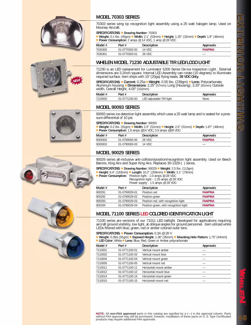
®
EX
TE
RIO
R L
IGH
TIN
GE
XT
ER
IOR
LIG
HT
ING
NOTE: All non-FAA approved parts in this catalog are signified by a (—) in the approval column. Parts without FAA approval may still be purchased, however, installation of these parts on U. S. Type Certificated products may require additional FAA approvals. 3535
MODEL 70303 SERIES70303 series wing tip recognition light assembly using a 25 watt halogen lamp. Used on Mooney Aircraft.SPECIFICATIONS: ● Drawing Number: 70303 ● Weight: 0.1 lbs. (45gm) ● Width: 2.1” (53mm) ● Height: 1.25” (32mm) ● Depth: 1.8” (46mm)● Power Consumption: 2 amps @ 14 VDC, 1 amp @ 28 VDCModel # Part # Description Approvals7030300 01-0770303-00 14 VDC FAA/PMA7030301 01-0770303-01 28 VDC —
WHELEN MODEL 71230 ADJUSTABLE TIR LED/LOGO LIGHT71230 is an LED replacement for Luminator 5200 Series De-Ice Inspection Light. External dimensions are 3.2inch square. Internal LED Assembly can rotate (10 degrees) to illuminate required surface. Item ships with 15" (20ga) flying leads. 28 VDC Only.SPECIFICATIONS: ● Current: 0.25a ● Weight: 0.55 lbs. (239gm) ● Lens: Polycarbonate, Aluminum housing ● Dimensions: 2.25" (57mm) Long (Housing), 3.20" (81mm) Outside width, Overall Height, 4.00" (102mm)
Model # Part # Description Approvals7123000 01-0771230-00 LED adjustable TIR light None
MODEL 90093 SERIES90093 series ice detection light assembly which uses a 25 watt lamp and is sealed for a pres-sure differential of 10 psi.SPECIFICATIONS: ● Drawing Number: 90093 ● Weight: 0.2 lbs. (91gm) ● Width: 2.0” (51mm) ● Height: 2.0” (51mm) ● Depth: 1.87” (48mm)● Power Consumption: 1.8 amps @14 VDC, 0.9 amps @28 VDCModel # Part # Description Approvals 9009300 01-0790093-00 28 VDC FAA/PMA9009303 01-0790093-03 14 VDC —
MODEL 90029 SERIES90029 series all-inclusive anti-collision/position/recognition light assembly. Used on Beech Barons, King Airs and Super King Airs. Replaces 30-1329-( ) series.SPECIFICATIONS: ● Drawing Number: 90029 ● Weight: 2.5 lbs. (113gm) ● Height: 6.4” (163mm) ● Length: 10.2” (259mm) ● Width: 3.1” (79mm)● Power Consumption: Position light - 1.0 amps @ 28 VDC Recognition light - 1.25 amps @ 28 VDC Power supply - 1.5 amps @ 28 VDCModel # Part # Description Approvals900291 01-0790029-01 Position red FAA/PMA900292 01-0790029-02 Position green FAA/PMA900293 01-0790029-03 Position red, with recognition light FAA/PMA900294 01-0790029-04 Position green, with recognition light FAA/PMA
MODEL 71100 SERIES LED COLORED IDENTIFICATION LIGHT71100 series are versions of our 71011 LED taillight. Developed for applications requiring aircraft ground visibility, low light, at oblique angles for ground personnel. Item utilized white LEDs filtered with blue, green, red or amber colored outer lens.SPECIFICATIONS: ● Power Consumption: 0.3A @ 28 V● Weight: 0.2lbs (91gm) ● Exposed Height: 1.36" (35mm) ● Mounting Hole Pattern: 1.75" (44mm)● LED Color: White ● Lens: Blue, Red, Green or Amber polycarbonate Model # Part # Description Approvals7110001 01-0771100-01 Vertical mount amber —7110002 01-0771100-02 Vertical mount blue —7110004 01-0771100-04 Vertical mount green —7110005 01-0771100-05 Vertical mount red —7110011 01-0771100-11 Horizontal mount amber —7110012 01-0771100-12 Horizontal mount blue —7110014 01-0771100-14 Horizontal mount green —7110015 01-0771100-15 Horizontal mount red —
NEW!
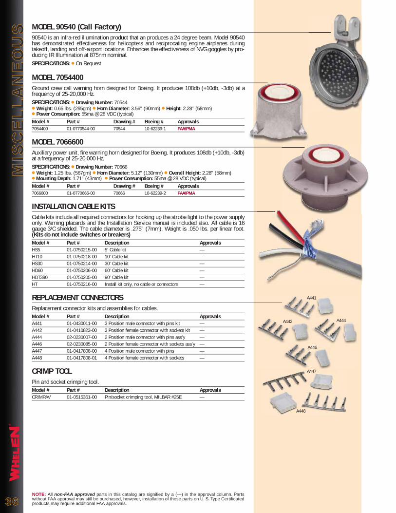
®
MIS
CE
LL
AN
EO
US
MIS
CE
LL
AN
EO
US
NOTE: All non-FAA approved parts in this catalog are signified by a (—) in the approval column. Parts without FAA approval may still be purchased, however, installation of these parts on U. S. Type Certificated products may require additional FAA approvals.3636
MODEL 90540 (Call Factory)90540 is an infra-red illumination product that an produces a 24 degree beam. Model 90540 has demonstrated effectiveness for helicopters and reciprocating engine airplanes during takeoff, landing and off-airport locations. Enhances the effectiveness of NVG goggles by pro-ducing IR Illumination at 875nm nominal.SPECIFICATIONS: ● On Request
MODEL 7054400Ground crew call warning horn designed for Boeing. It produces 108db (+10db, -3db) at a frequency of 25-20,000 Hz.SPECIFICATIONS: ● Drawing Number: 70544● Weight: 0.65 lbs. (295gm) ● Horn Diameter: 3.56” (90mm) ● Height: 2.28” (58mm)● Power Consumption: 55ma @ 28 VDC (typical)Model # Part # Drawing # Boeing # Approvals7054400 01-0770544-00 70544 10-62239-1 FAA/PMA
MODEL 7066600Auxiliary power unit, fire warning horn designed for Boeing. It produces 108db (+10db, -3db) at a frequency of 25-20,000 Hz.SPECIFICATIONS: ● Drawing Number: 70666● Weight: 1.25 lbs. (567gm) ● Horn Diameter: 5.12” (130mm) ● Overall Height: 2.28” (58mm)● Mounting Depth: 1.71” (43mm) ● Power Consumption: 55ma @ 28 VDC (typical)Model # Part # Drawing # Boeing # Approvals7066600 01-0770666-00 70666 10-62239-2 FAA/PMA
INSTALLATION CABLE KITSCable kits include all required connectors for hooking up the strobe light to the power supply only. Warning placards and the Installation Service manual is included also. All cable is 16 gauge 3/C shielded. The cable diameter is .275” (7mm). Weight is .050 lbs. per linear foot. (Kits do not include switches or breakers)Model # Part # Description ApprovalsHS5 01-0750215-00 5’ Cable kit —HT10 01-0750218-00 10’ Cable kit —HS30 01-0750214-00 30’ Cable kit —HD60 01-0750206-00 60’ Cable kit —HDT390 01-0750205-00 90’ Cable kit —HT 01-0750216-00 Install kit only, no cable or connectors —
REPLACEMENT CONNECTORSReplacement connector kits and assemblies for cables.Model # Part # Description ApprovalsA441 01-0430011-00 3 Position male connector with pins kit —A442 01-0410823-00 3 Position female connector with sockets kit —A444 02-0230007-00 2 Position male connector with pins ass’y —A446 02-0230085-00 2 Position female connector with sockets ass’y —A447 01-0417808-00 4 Position male connector with pins —A448 01-0417808-01 4 Position female connector with sockets —
CRIMP TOOLPin and socket crimping tool.Model # Part # Description ApprovalsCRIMPAV 01-0515361-00 Pin/socket crimping tool, MILBAR #25E —
A441
A442
A446
A444
A447
A448
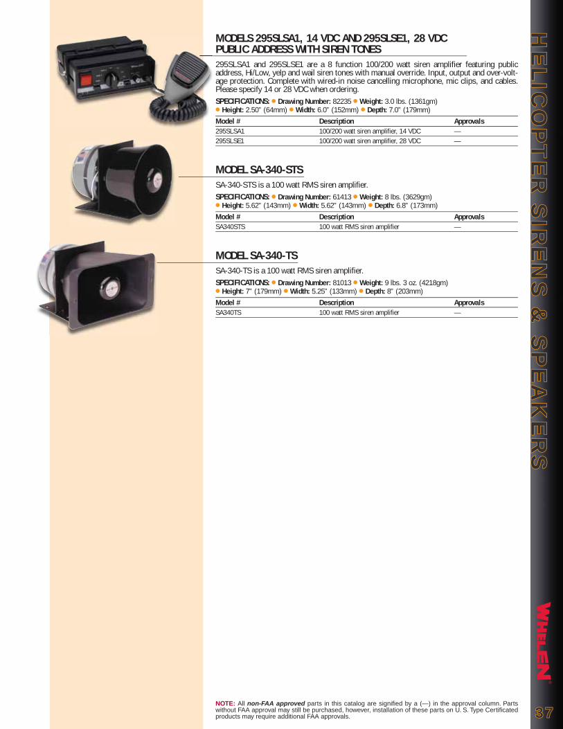
®
HE
LIC
OP
TE
R S
IRE
NS
& S
PE
AK
ER
SH
EL
ICO
PT
ER
SIR
EN
S &
SP
EA
KE
RS
NOTE: All non-FAA approved parts in this catalog are signified by a (—) in the approval column. Parts without FAA approval may still be purchased, however, installation of these parts on U. S. Type Certificated products may require additional FAA approvals. 3737
MODELS 295SLSA1, 14 VDC AND 295SLSE1, 28 VDC PUBLIC ADDRESS WITH SIREN TONES295SLSA1 and 295SLSE1 are a 8 function 100/200 watt siren amplifier featuring public address, Hi/Low, yelp and wail siren tones with manual override. Input, output and over-volt-age protection. Complete with wired-in noise cancelling microphone, mic clips, and cables. Please specify 14 or 28 VDC when ordering.SPECIFICATIONS: ● Drawing Number: 82235 ● Weight: 3.0 lbs. (1361gm)● Height: 2.50” (64mm) ● Width: 6.0” (152mm) ● Depth: 7.0” (179mm) Model # Description Approvals295SLSA1 100/200 watt siren amplifier, 14 VDC —295SLSE1 100/200 watt siren amplifier, 28 VDC —
MODEL SA-340-STSSA-340-STS is a 100 watt RMS siren amplifier.SPECIFICATIONS: ● Drawing Number: 61413 ● Weight: 8 lbs. (3629gm)● Height: 5.62” (143mm) ● Width: 5.62” (143mm) ● Depth: 6.8” (173mm)Model # Description ApprovalsSA340STS 100 watt RMS siren amplifier —
MODEL SA-340-TSSA-340-TS is a 100 watt RMS siren amplifier.SPECIFICATIONS: ● Drawing Number: 81013 ● Weight: 9 lbs. 3 oz. (4218gm)● Height: 7” (179mm) ● Width: 5.25” (133mm) ● Depth: 8” (203mm)Model # Description ApprovalsSA340TS 100 watt RMS siren amplifier —
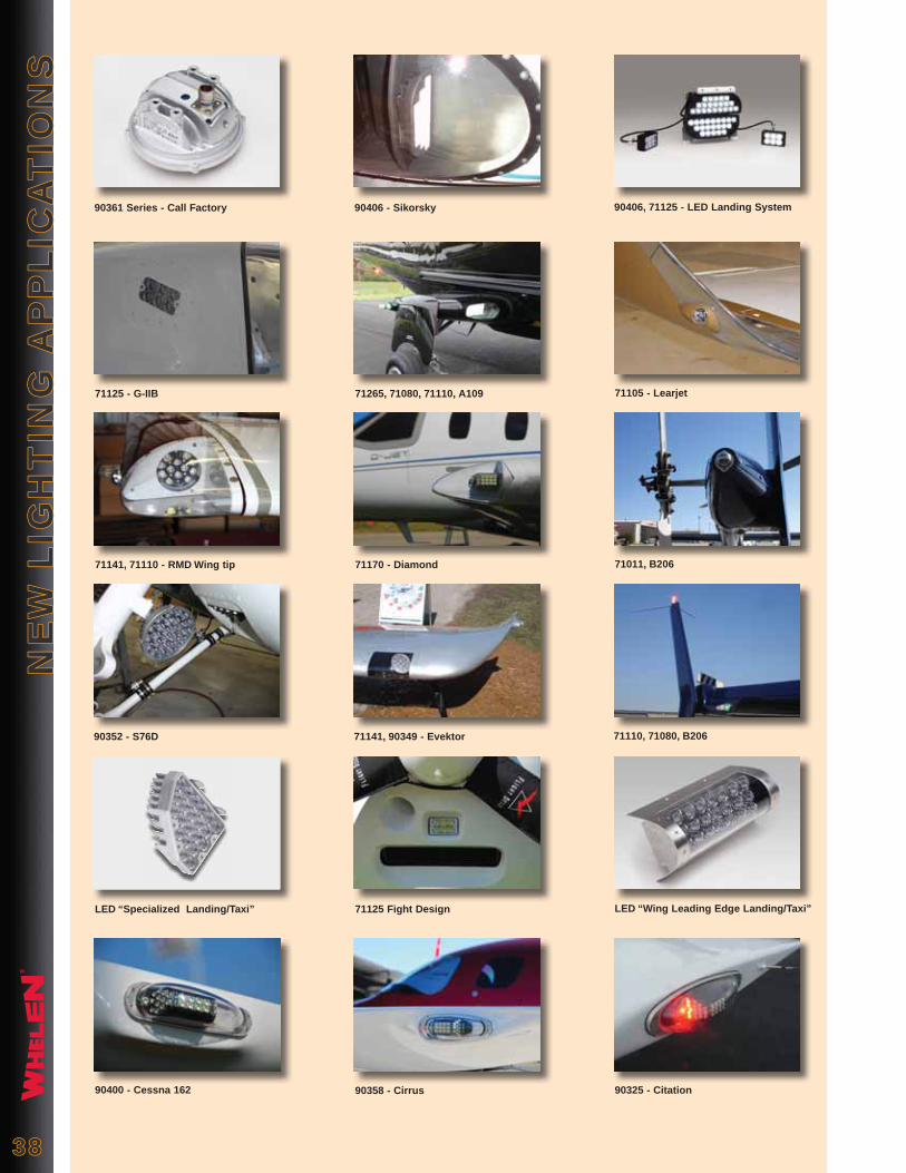
®
3838
LED “Wing Leading Edge Landing/Taxi”LED “Specialized Landing/Taxi” 71125 Fight Design
71110, 71080, B20690352 - S76D 71141, 90349 - Evektor
71011, B20671141, 71110 - RMD Wing tip 71170 - Diamond
90406, 71125 - LED Landing System90361 Series - Call Factory 90406 - Sikorsky
71105 - Learjet71125 - G-IIB 71265, 71080, 71110, A109
90325 - Citation90400 - Cessna 162 90358 - Cirrus
NE
W L
IGH
TIN
G A
PP
LIC
AT
ION
SN
EW
LIG
HT
ING
AP
PL
ICA
TIO
NS
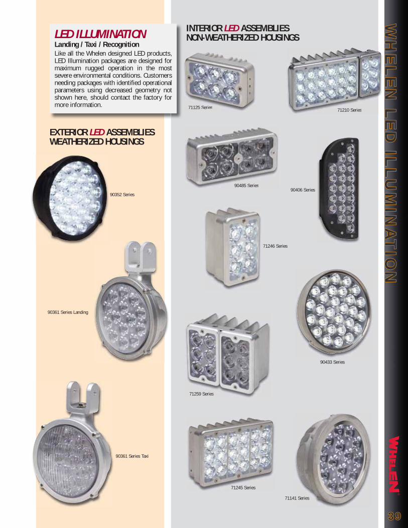
®
WH
EL
EN
LE
D IL
LU
MIN
AT
ION
WH
EL
EN
LE
D IL
LU
MIN
AT
ION
3939
EXTERIOR LED ASSEMBLIES WEATHERIZED HOUSINGS
90352 Series
90361 Series Landing
90361 Series Taxi
INTERIOR LED ASSEMBLIESNON-WEATHERIZED HOUSINGS
71125 Series
71259 Series
90485 Series
71210 Series71125 Series
71259 Series
90485 Series
71210 Series
71245 Series
71141 Series
90406 Series
90433 Series
71246 Series
LED ILLUMINATIONLanding / Taxi / RecognitionLike all the Whelen designed LED products, LED Illumination packages are designed for maximum rugged operation in the most severe environmental conditions. Customers needing packages with identified operational parameters using decreased geometry not shown here, should contact the factory for more information.

®
4040
51 Winthrop Road, Chester, Connecticut 06412-0684PHONE: (860) 526-9504 ● FAX: (860) 526-2009
Web: www.whelen.com ● Email: [email protected] 800 FAX Order Line Only: (800) 637-8762
Whelen Products are proudly made in the U.S.A.
For a complete look at Whelen and it’s line of Aviation, Automotive,
and Mass Notification Products...
Please visit us on the WEB at:
www.whelen.com
LED & STROBE TECHNOLOGY LED & STROBE TECHNOLOGY FOR YOUR AIRCRAFT FROMFOR YOUR AIRCRAFT FROM
WHELEN ENGINEERING...WHELEN ENGINEERING...THE LEADER IN AVIATION LIGHTING!THE LEADER IN AVIATION LIGHTING!
Model 71055
®
ENGINEERING COMPANY, INC.
Background Photo Courtesy of Cessna Flyer Magazine December 2008
Model 71141
Model 71110

STROBE POWER SUPPLY REPLACEMENT LISTINGOld Part Number Old Model Number Description Current Replacement
A413,HS-41-14 HS,41 Single strobe unit, SingleFlash, 14 VDC, 33 joule
A413,HS-41-28 HS,41 Single strobe unit, SingleFlash, 28 VDC, 33 joule
A413,HD-14 HD Dual strobe unit, SingleFlash, 14 VDC, alternating
A413,HD-28 HD Dual strobe unit, SingleFlash, 28 VDC, alternating
A413,HD-42-14 HD,42 Dual strobe unit, SingleFlash, 14 VDC, alternating, 33 joule
A413,HD-42-28 HD,42 Dual strobe unit, SingleFlash, 28 VDC, alternating, 33 joule
A413,T2-14 HD,T2 Dual strobe unit, SingleFlash, 14 VDC, simultaneous, 16 joule
A413,T2-28 HD,T2 Dual strobe unit, SingleFlash, 28 VDC, simultaneous, 16 joule
A413,T2-DF-14 HD,T2,DF Dual strobe unit, DoubleFlash, 14 VDC, simultaneous, 16 joule
A413,T2-DF-28 HD,T2,DF Dual strobe unit, DoubleFlash, 28 VDC, simultaneous, 16 joule
A413,T3-14 HD,T3 3 strobe unit, SingleFlash, 14 VDC, w/trigger function
A413,T3-28 HD,T3 3 strobe unit, SingleFlash, 28 VDC, w/trigger function
A413,HD,DF-14 HD,DF 3 strobe unit, DoubleFlash, 14 VDC
A413,HD,DF-28 HD,DF 3 strobe unit, DoubleFlash, 28 VDC
A413,T3-DF-14 HD,T3,DF 3 strobe unit, DoubleFlash, 14 VDC, w/trigger function
A413,T3-DF-28 HD,T3,DF 3 strobe unit, DoubleFlash, 28 VDC, w/trigger function
A413A,HDA-DF-14 HDA,DF-14 4 strobe unit, DoubleFlash, 14 VDC
A413A,HDA-DF-28 HDA,DF-28 4 strobe unit, DoubleFlash, 28 VDC
A413A,HDA-DF-14/28 HDA,DF-14/28 4 strobe unit, DoubleFlash, 14 or 28 VDC
A413A,HDA-CF-14/28 HDA,CF-14/28 4 strobe unit, CometFlash®, 14 or 28 VDC
A412A,HS-14 HS,14 Single strobe unit, SingleFlash, 14 VDC
A412A,HS-28 HS,28 Single strobe unit, SingleFlash, 28 VDC
A412A,HS,DF-14 HS,DF-14 Single strobe unit, DoubleFlash, 14 VDC
A412A,HS,DF-28 HS,DF-28 Single strobe unit, DoubleFlash, 28 VDC
A490,TS-14 HTS Single strobe unit, SingleFlash, 14 VDC
A490,TS-28 HTS Single strobe unit, SingleFlash, 28 VDC
A490A,TS,DF HTS-DF Single strobe unit, DoubleFlash, 14 or 28 VDC
A490A,TS,CF-14/28 HTS-CF Single strobe unit, CometFlash, 14 or 28 VDC
A490,T-14 HT Single strobe unit, SingleFlash, 14 VDC
A490,T-28 HT Single strobe unit, SingleFlash, 28 VDC
A490,T,DF-14 HT,DF Single strobe unit, DoubleFlash, 14 VDC
A490,T,DF-28 HT,DF Single strobe unit, DoubleFlash, 28 VDC
A490,T,DF-14/28 HT,DF Single strobe unit, DoubleFlash, 14 or 28 VDC
A490,T,CF-14/28 HT,CF Single strobe unit, CometFlash, 14 or 28 VDC
A490,TC,DF-14 HTC,DF Single strobe unit, DoubleFlash, 14 VDC with mounting plate
A490,TC,DF-28 HTC,DF Single strobe unit, DoubleFlash, 28 VDC with mounting plate
A490,TC,DF-14/28 HTC,DF Single strobe unit, DoubleFlash, 14 or 28 VDC w/mounting plate
A490,TC,CF-14/28 HTC,CF Single strobe unit, CometFlash, 14 or 28 VDC w/mtg. plate
HR,14 Self-Contained strobe, 14 VDC
HR,28 Self-Contained strobe, 28 VDC
HR,DF,14 Self-Contained strobe, DoubleFlash 14 VDC
HR,DF,28 Self-Contained strobe, DoubleFlash 28 VDC
HR,DF,14/28 Self-Contained strobe, DoubleFlash 14 or 28 VDC
HR,DFA,14/28 Self-Contained strobe, DoubleFlash 14 or 28 VDC (A402A lens)
ST
RO
BE
PO
WE
R S
UP
PLY
RE
PL
AC
EM
EN
T L
IST
ING
ST
RO
BE
PO
WE
R S
UP
PLY
RE
PL
AC
EM
EN
T L
IST
ING
4141
Model HDACFP/N 01-0770028-05
Model A490ATSCP/N 01-0770062-03
Model A490TCFP/N 01-0770006-08
Model A490TCCFP/N 01-0770006-09
Model HRCFAP/N 01-0770029-( )Specify lens colorR=Red, W=WhiteS=Split Red/White

®
ST
RO
BE
SY
ST
EM
RE
CO
MM
EN
DA
TIO
NS
ST
RO
BE
SY
ST
EM
RE
CO
MM
EN
DA
TIO
NS Strobe System Recommendations
Whelen does not have specific kits set up (Contact Authorized Whelen Distributor). The following are strobe system recommendations. The basic model/part numbers are given. In some cases the aircraft voltage and mounting location of the light are needed to specify the exact model/part number.
Raytheon/Beech AircraftEarly Model Twin Engine through 1969 – The slanted wing tip requires custom fabricated brackets for mounting the strobe lights. The following is recommended:
Quantity Model Part # Description1 each HDACF 01-0770028-05 Power supply2 each A625 01-0770058-03 Wing tip strobe light assembly1 each HD60 01-0750206-00 Installation package
REF: All Barons (95-55, A55, B55, C55, D55) & All Travel Airs 1957 thru 1969
Single Engine 1967 through 1973 – Use position lights installed under clear fairings at the wing tips most forward position. Specify 14 or 28 VDC. To convert to Whelen strobes the following is recommended:
Quantity Model Part # Description1 each HDACF 01-0770028-05 Power supply2 each A625 01-0770058-03 Wing tip strobe light1 each A500AV14 or 01-0770024-00 Tail strobe/position light (lens mayas req. A500AV28 01-0770024-01 be removed to reduce heat build-up)1 each HDT390 01-0750205-00 Installation package
Early Model Single Engine through 1966 – Excluding any modified wing tip, use position lights at the wing tip extremity. To convert to Whelen strobes, the following is recommended:
Quantity Model Part # Description1 each HDACF 01-0770028-05 Power supply1 each A650PG14 01-0770054-00 Wing tip light1 each A650PR14 01-0770054-02 Wing tip light1 each HD60 01-0750206-00 Installation package ORNote: Model 7111001 and 7111002 can replace Model A650 for a LED solution
Single Engine 1974 and Later – Use a commonality wing tip, thatenlarged the clear fairing by approximately six inches. Specify 14 or 28 VDC. To convert to Whelen strobes, the following is recommended:
Quantity Model Part # Description1 each HDACF 01-0770028-05 Power supply2 each D900283 01-0790028-03 Wing tip strobe light1 each A500AV14 or 01-0770024-00 Tail strobe/position lightas req. A500AV28 01-0770024-011 each HDT390 01-0750205-00 Installation package
4242

®
ST
RO
BE
SY
ST
EM
RE
CO
MM
EN
DA
TIO
NS
ST
RO
BE
SY
ST
EM
RE
CO
MM
EN
DA
TIO
NS
Rotating Beacon Replacement - The round mechanical rotating beacon was used on the vertical fin of all Barons from 1961 thru 1969. Models using this light are 95-55 (1961), A55 (1962-63), B55 (1964-82), C55 (1966-1967), D55 (1968-1969). Note: the B55 Baron continued to use this beacon until production stopped in 1982.
To convert the existing beacon to a self-contained LED flashing beacon:
Quantity Model Part # Description1 as req. 7090004 01-0770900-04 14 VDC, red1 as req. 7090005 01-0770900-05 28 VDC, red1 as req. A440 19-130074-009 Mounting adapter (required for fuselage mounting)
To convert the existing beacon to a self-contained strobe beacon:
Quantity Model Part # Description1 as req. HRCFAR 01-0770029-29 Standard assembly, red lens1 as req. HRCFAW 01-0770029-30 Standard assembly, clear lens1 as req. HRCFAS 01-0770029-31 Standard assembly, split red/clear lens1 as req. A440 19-130074-009 Mounting adapter (required for fuselage mounting)
Raytheon/Beech Aircraft (Cont'd)
Baron Rudder Mount Oscillation Beacon Replacement - The mechanical oscillating beacon first appeared in 1970 on the then new E55, until 1982. All model 58's used it from 1970 thru 2000.
To convert the existing beacon to an LED flashing beacon:
Quantity Model Part # Description1 as req. 9008814 01-0790088-14 Upper mount, 5 hole, 2.25 lbs.
To convert the existing beacon to a Quartz Halogen flashing beacon:
Quantity Model Part # Description1 as req. 9004457 01-0790044-57 Upper mount, 5 hole, 2.25 lbs. (red)
.
Duke Oscillation Beacon Replacement - To convert the existing beacon to an LED flashing beacon:
Quantity Model Part # Description1 as req.* 9008812 01-0790088-12 Upper mount, 5 hole1 as req.* 9008818 01-0790088-18 Upper mount, 8 hole
To convert the existing beacon to a Quartz Halogen flashing beacon:
Quantity Model Part # Description1 as req.* 9004401 01-0790044-01 Upper mount, 5 hole1 as req.* 9004417 01-0790044-17 Upper mount, 8 hole
*Note - Check existing mounting hole pattern before ordering (5 or 8 hole)
4343

®
ST
RO
BE
SY
ST
EM
RE
CO
MM
EN
DA
TIO
NS
ST
RO
BE
SY
ST
EM
RE
CO
MM
EN
DA
TIO
NS Cessna Aircraft
Wing Tip Strobes for Early Model Single Engine through 1961 – Excluding any modified wing tip, use position lights at the wing tip extremity. To convert to Whelen strobes, the following is recommended:
Quantity Model Part # Description1 each HDACF 01-0770028-05 Power supply1 each A650PG14 01-0770054-00 Wing tip light1 each A650PR14 01-0770054-02 Wing tip light1 each HD60 01-0750206-00 Installation package
Wing Tip Strobes for Single Engine 1962 through 1969 – Requires modification to the factory wing tip to accommodate the light assemblies. To convert to Whelen strobes, the following is recommended:
Quantity Model Part # Description1 each HDACF 01-0770028-05 Power supply1 each A650PG14 01-0770054-00 Wing tip light1 each A650PR14 01-0770054-02 Wing tip light1 each HD60 01-0750206-00 Installation packageNote: Model 7111001 and 7111002 can replace Model A650 for a LED solution
Wing Tip Strobes for Single Engine 1970 and 1971 – Excluding any modified wing tip, also use position lights at the wing tip extremity, however, the retainers are too short to accommodate a custom installation. The Model A625 strobe lights are mounted aft of the position light lens retainers. To convert to Whelen strobes, the following is recommended:
Quantity Model Part # Description1 each HDACF 01-0770028-05 Power supply2 each A625 01-0770058-03 Wing tip strobe light assembly1 each HD60 01-0750206-00 Installation package
Wing Tip Strobes for Single Engine 1972 and Later – Excluding any modified wing tip, spare wires were installed at the factory from a switch position on the instrument panel to the farthest rib in each wing tip. This allows mounting of the power supplies adjacent to the strobe light, which reduces installation time significantly. Wing tip strobes were also an option in the early 70’s. We estimate that 40-50% had factory installed systems.Replacement Parts for Aircraft with Factory Installed Systems:Quantity Model Part # Description2 each A490TCCF 01-0770006-09 Wing tip strobe power supply2 each A427 02-0250274-00 Wing tip strobe tube2 each A428 68-4290001-30 Wing tip strobe lens
Recommended Parts for Aircraft without Factory Installed Systems:Quantity Model Part # Description2 each A490TCCF 01-0770006-09 Wing tip strobe power supply2 each A610 02-0250276-00 Wing tip strobe tube assembly2 each A612 68-2290005-30 Wing tip strobe lens1 each HT 01-0750216-00 Installation package
Note: A small percentage of 1972 and later aircraft used the 1962-1969 wing tip.
4444
Rotating Beacon Replacement - The round mechanical rotating beacon was used on early model single engine Cessna's from the late 50's through 1966. Twin Engine Cessna's started using the round mechanical rotating beacon in the 50's. Later model 400 Series used a teardrop beacon. Check existing beacon con-figuration before ordering.To convert the existing beacon to a self-contained LED flashing beacon:
Quantity Model Part # Description1 as req. 7090004 01-0770900-04 14 VDC, red1 as req. 7090005 01-0770900-05 28 VDC, red1 as req. A440 19-130074-009 Mounting adapter (required for fuselage mounting)

®
ST
RO
BE
SY
ST
EM
RE
CO
MM
EN
DA
TIO
NS
ST
RO
BE
SY
ST
EM
RE
CO
MM
EN
DA
TIO
NS
Cessna Aircraft (Cont'd)
Rotating Beacon Replacement - The round mechanical rotating beacon was used on early model single engine Cessna's from the late 50's through 1966. Twin Engine Cessna's started using the round mechanical rotating beacon in the 50's. Later model 400 Series used a teardrop beacon. Check existing beacon configuration before ordering.To convert the existing beacon to a self-contained strobe beacon:
Quantity Model Part # Description1 as req. HRCFAR 01-0770029-29 Standard assembly, red lens1 as req. HRCFAW 01-0770029-30 Standard assembly, clear lens1 as req. HRCFAS 01-0770029-31 Standard assembly, split red/clear lens1 as req. A440 19-130074-009 Mounting adapter (req. for fuselage mount)
Quartz Halogen Flasher Replacement for Single Engine Vertical Fin, 1967 & later – In 1967, Cessna changed from a rotating beacon to a quartz halogen flasher beacon. This has a 150 watt, 28 VDC quartz halogen lamp, or a 125 watt, 14 VDC quartz halogen lamp, operated from a solid-state electronic module. To convert to a Whelen strobe, the following is recommended:
Quantity Model Part # Description1 as req. A470AR 01-0770019-18 Strobe light assembly, red1 as req. A470AW 01-0770019-19 Strobe light assembly, white1 as req. A470AS 01-0770019-20 Strobe light assembly, split red/white1 each A490ATSC 01-0770062-03 Power supply assembly1 each H102 01-0730068-00 Mounting adapter1 each HT10 01-0750218-00 Installation packageNote: Model 71055 Self Contained LED Beacon can replace Model A470AR for a LED solution
4545
Cessna 300A, B, C & D Twin Engines – The system for these airplanes requires fabricated brackets for affixing the power supplies and for attaching the strobe to a new position light bracket.To convert to Whelen strobes, the following is recommended:
Quantity Model Part # Description3 each A490TCF 01-0770006-08 Power supply2 each A625 01-0770058-03 Wing tip strobe light1 each A500AV 01-0770024-01 Tail strobe/position light1 each HT 01-0750216-00 Installation package
The Remaining Cessna 300-400 Series Twin Engines – The system for these airplanes requires the same hardware as above, however, some had factory installed Grimes assemblies from approximately 1969 and later. To replace the existing system, all parts must be replaced and wiring must be changed. New fabricated brackets are required.
Cessna Citation Series – Whelen has an STC compliant system to convert factory installed Grimes wing tip strobes. The initial STC #ST22BO was for Citation 550, S550 & 560, Serial #128 thru 256. The following is recommended.System P/N – 01-0716164-03, (STC #ST22BO) includes:
Quantity Model Part # Description2 each 9010104 01-0790101-04 Power supply1 each 9015905 01-0790159-05 Strobe light assembly1 each 9015906 01-0790159-06 Strobe light assembly
Brackets & hardware for Installation
The second system, STC #ST0010BO, covers Serial #257 & later, and any aircraft that installed Cessna Service Bulletin #SB560-33-08 from Serial #0001 thru #0256. System P/N – 01-0716164-05, (STC #ST0010BO) includes:
Quantity Model Part # Description2 each 9010104 01-0790101-04 Power supply1 each 9020603 01-0790206-03 Strobe light assembly1 each 9020604 01-0790206-04 Strobe light assembly
Brackets & hardware for Installation
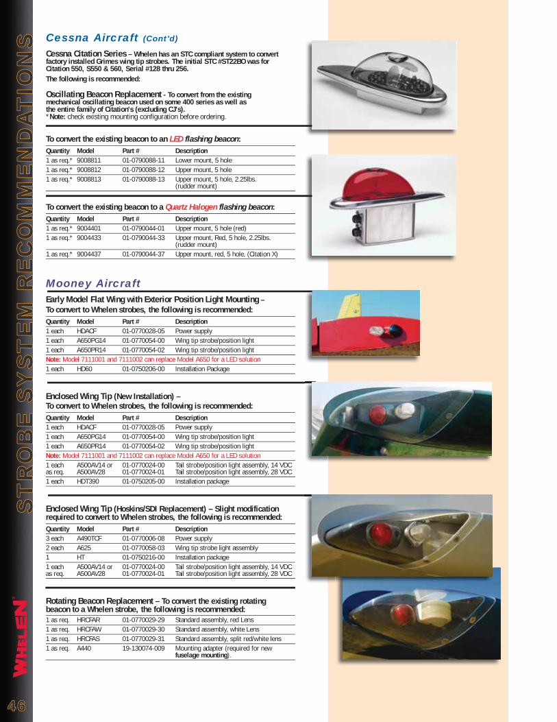
®
ST
RO
BE
SY
ST
EM
RE
CO
MM
EN
DA
TIO
NS
ST
RO
BE
SY
ST
EM
RE
CO
MM
EN
DA
TIO
NS
Mooney AircraftEarly Model Flat Wing with Exterior Position Light Mounting – To convert to Whelen strobes, the following is recommended:Quantity Model Part # Description1 each HDACF 01-0770028-05 Power supply1 each A650PG14 01-0770054-00 Wing tip strobe/position light1 each A650PR14 01-0770054-02 Wing tip strobe/position lightNote: Model 7111001 and 7111002 can replace Model A650 for a LED solution1 each HD60 01-0750206-00 Installation Package
Enclosed Wing Tip (New Installation) – To convert to Whelen strobes, the following is recommended:Quantity Model Part # Description1 each HDACF 01-0770028-05 Power supply1 each A650PG14 01-0770054-00 Wing tip strobe/position light1 each A650PR14 01-0770054-02 Wing tip strobe/position lightNote: Model 7111001 and 7111002 can replace Model A650 for a LED solution1 each A500AV14 or 01-0770024-00 Tail strobe/position light assembly, 14 VDCas req. A500AV28 01-0770024-01 Tail strobe/position light assembly, 28 VDC1 each HDT390 01-0750205-00 Installation package
Enclosed Wing Tip (Hoskins/SDI Replacement) – Slight modification required to convert to Whelen strobes, the following is recommended:Quantity Model Part # Description3 each A490TCF 01-0770006-08 Power supply2 each A625 01-0770058-03 Wing tip strobe light assembly1 HT 01-0750216-00 Installation package1 each A500AV14 or 01-0770024-00 Tail strobe/position light assembly, 14 VDCas req. A500AV28 01-0770024-01 Tail strobe/position light assembly, 28 VDC
Rotating Beacon Replacement – To convert the existing rotating beacon to a Whelen strobe, the following is recommended:1 as req. HRCFAR 01-0770029-29 Standard assembly, red Lens1 as req. HRCFAW 01-0770029-30 Standard assembly, white Lens1 as req. HRCFAS 01-0770029-31 Standard assembly, split red/white lens1 as req. A440 19-130074-009 Mounting adapter (required for new fuselage mounting).
Cessna Aircraft (Cont'd)
Cessna Citation Series – Whelen has an STC compliant system to convert factory installed Grimes wing tip strobes. The initial STC #ST22BO was for Citation 550, S550 & 560, Serial #128 thru 256. The following is recommended:
Oscillating Beacon Replacement - To convert from the existing mechanical oscillating beacon used on some 400 series as well as the entire family of Citation's (excluding CJ's). *Note: check existing mounting configuration before ordering.
To convert the existing beacon to an LED flashing beacon:Quantity Model Part # Description1 as req.* 9008811 01-0790088-11 Lower mount, 5 hole1 as req.* 9008812 01-0790088-12 Upper mount, 5 hole1 as req.* 9008813 01-0790088-13 Upper mount, 5 hole, 2.25lbs. (rudder mount)
To convert the existing beacon to a Quartz Halogen flashing beacon:Quantity Model Part # Description1 as req.* 9004401 01-0790044-01 Upper mount, 5 hole (red)1 as req.* 9004433 01-0790044-33 Upper mount, Red, 5 hole, 2.25lbs. (rudder mount)1 as req.* 9004437 01-0790044-37 Upper mount, red, 5 hole, (Citation X)
4646

®
ST
RO
BE
SY
ST
EM
RE
CO
MM
EN
DA
TIO
NS
ST
RO
BE
SY
ST
EM
RE
CO
MM
EN
DA
TIO
NS
Home built & Kit AircraftFor Aircraft with Standard Wing Tips – The most widely used system on the market, this provides all of the components for anti-collision and position lights without the need for a taillight. The power supply is mounted in the fuselage and shielded cable is run to the strobe lights. The following is recommended:
Quantity Model # Part # Description1 each HDACF 01-0770028-05 Power supply1 each A600PG14 01-0790006-00 Wing tip strobe/position/taillight, 14 VDC1 each A600PR14 01-0790006-02 Wing tip strobe/position/taillight, 14 VDCNote: Model 9034001 and 9034002 can replace Model A600 for a LED solution1 each HD60 01-0750206-00 Installation package
For Aircraft with Enclosed Wing Tip Fairings – If the position and strobe lights are mounted under a clear fairing, a third tail strobe is required. The following is recommended:
Quantity Model # Part # Description1 each HDACF 01-0770028-05 Power supply1 each A650PG14 01-0770054-00 Wing tip strobe/position light, 14 VDC1 each A650PR14 01-0770054-02 Wing tip strobe/position light, 14 VDCNote: Model 7111001 and 7111002 can replace Model A650 for a LED solution1 each A500AV14 01-0770024-00 Tail position/strobe light assembly1 each HDT390 01-0750205-00 Installation package
For Aircraft with Enclosed Wing Tip Fairings & Wing Tip Mounted PowerSupplies – If position and strobe lights are mounted under a clear fairing, the need for a third tail strobe is required. The following is recommended:
Quantity Model # Part # Description2 each A490ATSC 01-0770062-03 Power supply1 each A650PG14 01-0770054-00 Wing tip strobe/position/taillight, 14 VDC1 each A650PR14 01-0770054-02 Wing tip strobe/position/taillight, 14 VDCNote: Model 7111001 and 7111002 can replace Model A650 for a LED solution1 each A500AV14 01-0770024-00 Tail position/strobe light assembly, 14 VDC3 each HS5 01-0750215-00 Installation package
Piper AircraftSingle Engines & Piper Aztec – The same wing tip strobe system can be usedon most Piper aircraft models. To convert to strobes, the recommendation is:
Quantity Model # Part # Description1 each HDACF 01-0770028-05 Power supply1 each A650PG14 01-0770054-00 Wing tip strobe/position light, 14 VDC1 each A650PR14 01-0770054-02 Wing tip strobe/position light, 14 VDCNote: Model 7111001 and 7111002 can replace Model A650 for a LED solution1 each HD60 01-0750206-00 Installation package
Piper Navajo – System is as follows:
Quantity Model # Part # Description1 each HDACF 01-0770028-05 Power supply1 each A650PG28 01-0770054-01 Wing tip strobe/position light, 28 VDC1 each A650PR28 01-0770054-03 Wing tip strobe/position light, 28 VDCNote: Model 7111003 and 7111004 can replace Model A650 for a LED solution1 each A500AH28 01-0770024-03 Tail position/strobe light assembly, 28 VDC1 each HDT390 01-0750205-00 Installation package
Piper Cheyenne I, II, & IIXL – Factory equipped with Whelen strobes.
Rotating Beacon Replacement - To convert the existing beacon to a self- contained LED flashing beacon:
Quantity Model # Part # Description1 as req. 7090004 01-0770900-04 14 VDC, red1 as req. 7090005 01-0770900-05 28 VDC, red1 as req. A440 19-130074-009 Mounting adapter (req. fuselage mount)
To convert the existing beacon to a self-contained strobe beacon:Quantity Model # Part # Description1 as req. HRCFAR 01-0770029-29 Standard assembly, red Lens1 as req. HRCFAW 01-0770029-30 Standard assembly, clear Lens1 as req. HRCFAS 01-0770029-31 Standard assembly, split red/clear lens1 as req. A440 19-130074-009 Mounting adapter (req. fuselage mount)
4747

®
4848
Whelen Whelen LED Model Whelen P/N Equivalent Model # Cessna P/N Aeroflash P/N Description A427-3 38-0130106-00 - C622006-0105 80-0018 Strobe Tube Gasket/Spacer A427 02-0250274-00 - C622006-0106 073-0270 Strobe Flash Tube Assembly A427 02-0250274-00 - C622006-0108 073-0270 Strobe Flash Tube Assembly A428 68-4290001-30 - C622006-0103 111-0016 Wing tip Strobe Lens (Clear) A426 19-1900000-009 - - 101-0084 Lens Retainer A650PG14 01-0770054-00 7111001 - 073-0530G Strobe/Position Light Assembly 14 VDC, Green A650PR14 01-0770054-02 7111002 - 073-0530R Strobe/Position Light Assembly 14 VDC, Red A600PG14 01-0790006-00 9034001 - 073-0540G Strobe/Position/Tail Light Assembly 14 VDC, Green A600PR14 01-0790006-02 9034002 - 073-0540R Strobe/Position/Tail Light Assembly 14 VDC, Red A490TCCF 01-0770006-09 C622008-0101 152-0007 Strobe Power Supply, 14 VDC A490TCCF 01-0770006-09 C622007-0101 152-0008 Strobe Power Supply, 14 VDC A490TCCF 01-0770006-09 C622008-0102 152-0009 Strobe Power Supply, 28 VDC A490TCCF 01-0770006-09 C622007-0103 152-0010 Strobe Power Supply, 28 VDC A490TCCF 01-0770006-09 - 152-0011 Strobe Power Supply, 14 VDC, double flash 7050900 01-0770509-00 7105500 C621001-0106 151-0001 Flasher Assembly (Red 14 VDC) 7050903 01-0770509-03 7105501 C621001-0102 151-0004 Flasher Assembly (Red 28 VDC) SA406 02-0350053-00 - 073-0141 Strobe Flash Tube Assembly 28 VDC150W 34-0226010-91 C17312-1 040-0003 Halogen Lamp, 28 VDC 150W 12V125W 34-0212010-97 C17312-3 040-0028 Halogen Lamp, 14 VDC 125W
Whelen Whelen Whelen LED SDI/HOSKINS Model P/N Equivalent Model # P/N Description A650 01-0770053-00 701303-1 Wing tip Strobe Flash Tube Assembly, Left A650 01-0770053-00 701303-2 Wing tip Strobe Flash Tube Assembly, Right A430 01-0770031-00 30-0005-1 Wing tip Strobe Flash Tube Assembly (Amp Conn.) A625 01-0770058-00 30-0005-1 Wing tip Strobe Flash Tube Assembly (Amp Conn.) A625 01-0770058-00 30-0005 Wing tip Strobe Flash Tube Assembly (MS Conn.) A450 01-0770032-00 201803-1 Remote Strobe Light Assembly, White Lens A470AR 01-0770019-18 201803-2 Remote Strobe Light Assembly, Red Lens A470AW 01-0770019-19 201945-1 Remote Strobe Light Assembly, White Lens A470AR 01-0770019-18 201945-2 Remote Strobe Light Assembly, Red Lens A470AS 01-0770019-20 201945-7 Remote Strobe Light Assembly, Red/White Lens A500AV14 01-0770024-00 701557-1 Combination Nav/Strobe Tail Light 14 VDC A500AV28 01-0770024-01 701557-2 Combination Nav/Strobe Tail Light 28 VDC A500AV14 01-0770024-00 701557-1M Combination Nav/Strobe Tail Light 14 VDC (Mooney) A500AV14 01-0770024-00 701557-5 Combination Nav/Strobe Tail Light 14 VDC (Beech) A500AV28 01-0770024-01 701557-6 Combination Nav/Strobe Tail Light 28 VDC (Beech) HRCFAW 01-0770029-30 701620-1 Bright Star 14 VDC, Self Contained Strobe (Clear Lens) HRCFAR 01-0770029-29 7090004 701620-2 Bright Star 14 VDC, Self Contained Strobe (Red Lens) HRCFAS 01-0770029-31 701620-3 Bright Star 14 VDC, Self Contained Strobe (Red/Clear Lens) HRCFAW 01-0770029-30 700801-1 Silver Star 14-28 VDC, Self Contained Strobe (Clear Lens) HRCFAR 01-0770029-29 7090005 700801-2 Silver Star 14-28 VDC, Self Contained Strobe (Red Lens) HRCFAS 01-0770029-31 700801-7 Silver Star 14-28 VDC, Self Contained Strobe (Red/Clear Lens) 7028523 01-0770285-23 700801-H-1 Silver Star 14-28 VDC, Self Contained Strobe (Clear Lens) Helicopter 7028525 01-0770285-25 7090501 700801-H-2 Silver Star 14-28 VDC, Self Contained Strobe (Red Lens) Helicopter 7028524 01-0770285-24 700801-H-7 Silver Star 14-28 VDC, Self Contained Strobe (Red/Clear Lens) Helicopter A490TCF 01-0770006-08 701295-3 Strobe Power Supply (14 VDC) A490TCF 01-0770006-08 701295-4 Strobe Power Supply (24V) D900287 01-0790028-07 701148-7-2 Remote Strobe Light Fixture W/MS connector
Whelen Whelen LED Grimes P/N Whelen P/N Model Equivalent Model # Description A1280-1 68-4230020-30 W1284C Position Light Lens, Clear A1280-2 68-4230020-50 W1284R Position Light Lens, Red A1280-3 68-4230020-40 W1284G Position Light Lens, Green A1285G-14 01-0770001-41 W1285PG1 Position Light Assembly, Green, 14 VDC A1285G-28 01-0770001-42 W1285PG2 Position Light Assembly, Green, 28 VDC A1285R-14 01-0770001-51 W1285PR1 Position Light Assembly, Red, 14 VDC A1285R-28 01-0770001-52 W1285PR2 Position Light Assembly, Red, 28 VDC A1719 01-0770106-( ) A315LO-( ) Cockpit Utility Light A1815AG-14 01-0770082-02 W1250PG1 Position Light Assembly, Green, 14 VDC A1815AG-28 01-0770082-03 W1250PG2 7101501 Position Light Assembly, Green, 28 VDC A1815AR-14 01-0770082-00 W1250PR1 Position Light Assembly, Red, 14 VDC A1815AR-28 01-0770082-01 W1250PR2 7101502 Position Light Assembly, Red, 28 VDC A2064-12 or 14 01-0770034-00 A555AV14 7101112 Tail Position Light Assembly, 14 VDC A2064-24 or 28 01-0770034-01 A555AV28 7101102 Tail Position Light Assembly, 28 VDC A4174-24 34-0070372-01 WA4174-24 Reflector Lamp, 28 VDC, 40W A5413-1 68-3670390-30 WA4513-1 Lens, Aviation White A5395 01-0770113-( ) A315HI-( ) Cockpit Utility Light A6458 27-0270382-00 W6458 Motor, 28 VDC A6532 27-0270381-00 W6532 Motor, 28 VDC A6795 01-0770348-( ) 70348( ) Post Light A7079B-12 34-0070371-02 WA7079B-12 Reflector Lamp, 14 VDC, 40W
WHELEN/SDI/HOSKINS CROSS REFERENCE LIST
WHELEN/GRIMES CROSS REFERENCE LIST
WHELEN/AEROFLASH/CESSNA CROSS REFERENCE LISTW
HE
LE
N C
RO
SS
RE
FE
RE
NC
E L
IST
WH
EL
EN
CR
OS
S R
EF
ER
EN
CE
LIS
T

®
4949
Whelen Whelen LED Grimes P/N Whelen P/N Model Equivalent Model # Description A7079B-24 34-0070371-01 WA7079B-24 Reflector Lamp, 28 VDC, 40W A7512-12 34-0414020-65 W1290-14 Reflector Lamp, 14 VDC, 26W A7512-24 34-0428020-65 W1290-28 Reflector Lamp, 28 VDC, 26W A8970 01-0770119-( ) A350CNRD-( ) Post Light A8970B 01-0770119-( ) A350CNIW-( ) Post Light A8970C 01-0770119-( ) A350CNCL-( ) Post Light A8970IR 01-0770119-( ) A350CNRD-( ) Post Light A9906-7 34-0050315-01 WA9906-7 Lamp, miniature threaded, 28 VDC B3550-( ) 01-0770142-( ) A360-( ) 70813 series Cabin Light Assembly B3555-( ) 01-0770142-( ) A360S-( ) Cabin Light Assembly (w/switch) B4150B 01-0770155-01 A715-1 Landing Light Housing (Par-36) D6490 01-0790095-( ) 90095-( ) Landing Light Housing (Par-46) D7080A-( ) 01-0770029-( ) HRCFA( ) 70900 series Self-Contained Strobe Light G7740A-( ) 01-0770029-( ) HRCFA( ) 70900 series Self-Contained Strobe Light G8400-( ) 01-0770029-( ) HRCFA( ) 70900 series Self-Contained Strobe Light G9950-( ) 01-0790044-( ) 90044( ) 90088 series Flashing Beacon 10-0031-( ) 01-0770210-( ) 70210( ) Threshold Light Assembly 10-0035-( ) C702321 Aisle Light 10-0644-1 01-0770061-( ) A325ML( ) Map light 10-0644-3 01-0770061-( ) A325FL( ) Map light 11631 34-0070372-02 W11631 Reflector Lamp, 6.2V, 40W 15-0083-( ) 01-0770104-( ) A300( ) Map light 1512 34-0070373-01 W1512 Reflector Lamp, 12V, 21W 1524 34-0070373-03 W1524 Reflector Lamp, 24V, 21W 16870 34-0070371-03 W16870 Lamp 1982SP 34-0070403-00 W1982SP Lamp, 28 VDC, 75W 30-0437-1 01-0770030-01 SACF 70900 series Self-Contained Strobe 30-0437-100 01-0770029-( ) HRCFA( ) 70900 series Self-Contained Strobe 30-0465-5 01-0770032-00 A450 Remote Strobe Head Assembly 30-0467-( ) 01-0790028-07 D90028-7 Wing tip Strobe Light 30-0467-( ) 01-0790028-09 D90028-9 Tail Strobe Light 30-0504-1 01-0770019-19 A470AW Remote Strobe Light Assembly, White 30-0504-3 01-0770019-18 A470AR Remote Strobe Light Assembly, Red 30-0516-( ) 01-0770024-( ) A500AV( ) Tail Strobe/Position Light Assembly 30-0531-1 01-0770058-03 A625 Remote Strobe Light Assembly 30-0538-1 01-0770054-02 A650PR14 7111002 Strobe/Position Light Assembly, Red, 14 VDC 30-0538-11 01-0770053-00 A650 Strobe Assembly, Modification required 30-0538-2 01-0770054-00 A650PG14 7111001 Strobe/Position Light Assembly, Green, 14 VDC 30-0538-3 01-0770054-03 A650PR28 7111004 Strobe/Position Light Assembly, Red, 28 VDC 30-0538-4 01-0770054-01 A650PG28 7111003 Strobe/Position Light Assembly, Green, 28 VDC 30-0815-( ) 01-0750139-( ) A512A( ) Strobe Tube & Socket Assembly 30-1329-( ) 01-0790029-( ) 90029( ) Strobe/Position Light Assembly 30-0863-1 01-0770239-( ) 70239( ) Strobe/Position Light Assembly 30-1331-( ) 01-0790028-( ) D90028( ) Strobe Lighthead 30-1467-( ) 01-0790028-( ) D90028( ) Strobe Lighthead 30-1661-( ) 01-0770486-01 / -02 7048601 / 7048602 Navigation Light/Position Light used on Fairchild Metros 31-2645-1 02-0250274-00 A427 Flash-tube Assembly 36170-( ) 01-0770190-( ) C70190( ) 71144 series Goose Neck Light 40-0100-( ) 01-0790044-( ) 90044( ) 90088 series Flasher Beacon 40-0117-( ) 01-0790044-( ) 90044( ) 90088 series Flasher Beacon 40-0127-( ) 01-0790044-( ) 90044( ) 90088 series Flasher Beacon 40-0129-( ) 01-0770029-( ) HRCFA( ) 70900 series Self-Contained Strobe light 55-0069-1 27-0270383-00 W55-0069-1 Motor, 28 VDC 55-0221-1 36-0170384-01 W55-0221-1 Strobe Tube, Pyrex 55-0221-5 36-0170384-02 W55-0221-5 Strobe Tube, Quartz 55-0331-3 36-0170386-01 W55-0331-3 Strobe Tube, Quartz 55-0681-7 36-0170387-01 W55-0681-7 Strobe Tube, Quartz 55-0723-1 36-0170388-01 W55-0723-1 Strobe Tube, Quartz 60-1431-1 01-0770028-05 HDACF Power Supply 60-1431-3 01-0770028-05 HDACF Power Supply 60-1592-5 01-0770028-05 HDACF Power Supply 60-1592-11 01-0770028-05 HDACF Power Supply 60-1750-1 01-0790079-04 90079-04 Power Supply, MS Connectors 60-1750-3 01-0790079-04 90079-04 Power Supply, MS Connectors 60-2471-3 01-0790080-01 90080-01 Power Supply 60-2799-( ) 01-0790101-05 90101-05 Power Supply, Wing-tip mount 60-2836-1 01-0770028-05 HDACF Power Supply 60-2927-1 01-0770028-05 HDACF Power Supply 626 34-0070389-00 W626 Reflector Lamp, 6.2V, 40W 628 34-0070373-02 W628 Reflector Lamp, 26.5V, 26W 632 34-0070375-01 W632 Lamp, Tail Light, 28 VDC 674 34-0070374-01 W674 Lamp, Reading Light, 28 VDC 678 34-0070391-01 W678 Lamp, Tail Light, 28 VDC 684-24 34-0070392-01 W68424 Reflector Lamp, 28 VDC, 40W 692 34-0270398-9H W692 Lamp. D.C. Bayonet, 28 VDC, 25W
WHELEN/GRIMES CROSS REFERENCE LISTW
HE
LE
N C
RO
SS
RE
FE
RE
NC
E L
IST
WH
EL
EN
CR
OS
S R
EF
ER
EN
CE
LIS
T

®
5050
Breakdown Model Number Part Number
A350CN-IW-BK-LG-6 A350CN00 01-0770119-00
A350CN-RD-BK-LG-6 A350CN01 01-0770119-01
A350CN-CL-BK-LG-6 A350CN02 01-0770119-02
A350CN-IW-BK-SH-6 A350CN03 01-0770119-03
A350CN-RD-BK-SH-6 A350CN04 01-0770119-04
A350CN-CL-BK-SH-6 A350CN05 01-0770119-05
A350CN-IW-BK-LG-14 A350CN06 01-0770119-06
A350CN-RD-BK-LG-14 A350CN07 01-0770119-07
A350CN-CL-BK-LG-14 A350CN08 01-0770119-08
A350CN-IW-BK-SH-14 A350CN09 01-0770119-09
A350CN-RD-BK-SH-14 A350CN10 01-0770119-10
A350CN-CL-BK-SH-14 A350CN11 01-0770119-11
A350CN-IW-BK-LG-28 A350CN12 01-0770119-12
A350CN-RD-BK-LG-28 A350CN13 01-0770119-13
A350CN-CL-BK-LG-28 A350CN14 01-0770119-14
A350CN-IW-BK-SH-28 A350CN15 01-0770119-15
A350CN-RD-BK-SH-28 A350CN16 01-0770119-16
A350CN-CL-BK-SH-28 A350CN17 01-0770119-17
A350CN-IW-GR-LG-6 A350CN18 01-0770119-18
A350CN-RD-GR-LG-6 A350CN19 01-0770119-19
A350CN-CL-GR-LG-6 A350CN20 01-0770119-20
A350CN-IW-GR-SH-6 A350CN21 01-0770119-21
A350CN-RD-GR-SH-6 A350CN22 01-0770119-22
A350CN-CL-GR-SH-6 A350CN23 01-0770119-23
A350CN-IW-GR-LG-14 A350CN24 01-0770119-24
A350CN-RD-GR-LG-14 A350CN25 01-0770119-25
A350CN-CL-GR-LG-14 A350CN26 01-0770119-26
A350CN-IW-GR-SH-14 A350CN27 01-0770119-27
A350CN-RD-GR-SH-14 A350CN28 01-0770119-28
A350CN-CL-GR-SH-14 A350CN29 01-0770119-29
A350CN-IW-GR-LG-28 A350CN30 01-0770119-30
A350CN-RD-GR-LG-28 A350CN31 01-0770119-31
A350CN-CL-GR-LG-28 A350CN32 01-0770119-32
A350CN-IW-GR-SH-28 A350CN33 01-0770119-33
A350CN-RD-GR-SH-28 A350CN34 01-0770119-34
A350CN-CL-GR-SH-28 A350CN35 01-0770119-35
POST LIGHT CROSS REFERENCE CHARTW
HE
LE
N C
RO
SS
RE
FE
RE
NC
E L
IST
WH
EL
EN
CR
OS
S R
EF
ER
EN
CE
LIS
T
®
5151
ENGINEERING COMPANY, INC.
®
51 Winthrop Road, Chester, Connecticut 06412-0684 ● PHONE: (860) 526-9504 ● FAX: (860) 526-2009 Web: www.whelen.com ● Email: [email protected] ● Whelen 800 FAX Order Line Only: (800) 637-8762
For a complete look at Whelen and it’s line of Aviation, Automotive, Industrial,
and Outdoor Warning Products...
Whelen Productsare proudly made
in the U.S.A.
For the Latest in LED Technology for Helicopter and General Aviation Lighting!
"ITS TIME TO GET LEDON YOUR AIRCRAFT!"
When you're attempting an around the world record in an unmodified A109, you better have the reliability of Whelen's LED Aviation lighting. In the cockpit, Landing/ Taxi, Anticollision & Navigation, our products are stateof the art. Visit www.whelen.com, click aviation link to find a distributor who will help upgrade your aircraft.
"ITS TIME TO GET LEDON YOUR AIRCRAFT!"
Please visit us on the WEB at: www.whelen.com
HE
LIC
OP
TE
R L
IGH
TIN
GH
EL
ICO
PT
ER
LIG
HT
ING
Congratulations N1US around the world Helicopter speed record August 2008

2009 Whelen Engineering Company, Inc. 11015J-Rev 1-AVCAT09-0609 Printed in the U.S.A.