safety light curtain f3sj-a p series (version 2) · 2018-05-21 · introduction thank you for...
TRANSCRIPT

F3SJ-A□□□□P□□ Series (Version 2)Safety Light Curtain
User's Manual
Cat. No. SCHG-718J

Introduction
Thank you for purchasing the F3SJ Series Safety Light Curtain (hereinafter referred to as the "F3SJ" ).This is the instruction Manual describing the use of F3SJ.Always heed the following points when using the F3SJ:
Be sure to have F3SJ be handled by a "Responsible Person" who is well aware of and familiar with the machine to be installed.The term "Responsible Person" used in this Instruction Manual means the person qualified, authorized and responsible to secure"safety" in each process of the design, installation, operation, maintenance services and disposition of the machine.It is assumed that F3SJ will be used properly according to the installation environment, performance and function of the machine.Responsible Person should conduct risk assessment on the machine and determine the suitability of this product before installation.Read this Manual thoroughly to understand and make good use of the descriptions before installing and operating the product.Keep this Manual at the place where the operator can refer to whenever necessary.
Original instructions

iF3SJ-A
User’s Manual
Introduction
E
Legislation and Standards
1. Application of a F3SJ-A sensor alone cannot receive type approval provided by Article 44-2 of the LabourSafety and Health Law of Japan. It is necessary to apply it in a system. Therefore, when using the F3SJ-Ain Japan as a "safety system for pressing or shearing machines" prescribed in Article 42 of that law, thesystem must receive type approval.
2. The F3SJ-A is electro-sensitive protective equipment (ESPE) in accordance with European Union (EU)Machinery Directive Index Annex V, Item 2.
3. EC Declaration of Conformity OMRON declares that the F3SJ-A is in conformity with the requirements of the following EC Directives:
Machinery Directive 2006/42/EC EMC Directive 2004/108/EC
4. The F3SJ-A is in conformity with the following standards:(1) European standards
EN61496-1 (Type 4 ESPE), CLC/TS 61496-2 (Type 4 AOPD), EN61508-1 through -3 (SIL3), EN ISO 13849-1:2008 (Category 4, PL e)
(2) International standardsIEC61496-1 (Type 4 ESPE), IEC61496-2 (Type 4 AOPD), IEC61508-1 through -3 (SIL3), ISO 13849-1:2006 (Category 4, PL e)
(3)JIS standardsJIS B 9704-1 (Type 4 ESPE), JIS B 9704-2 (Type 4 AOPD)
(4) North American Standards:UL61496-1(Type 4 ESPE), UL61496-2(Type 4 AOPD), UL508, UL1998, CAN/CSA 22.2 No.14, CAN/CSA 22.2 No.0.8
5. The F3SJ-A received the following approvals from the EU accredited body, TÜV SÜD Product Service GmbH: •EC Type-Examination in accordance with the EU Machinery Directive, Type 4 ESPE (EN61496-1),
Type 4 AOPD (CLC/TS 61496-2) •TÜV SÜD Product Service GmbH Type Approval, Type 4 ESPE (EN61496-1), Type 4 AOPD (CLC/TS
61496-2), SIL1, 2, 3 (EN 61508-1 through -3), EN ISO 13849-1:2008 (Category 4, PL e)
6. The F3SJ-A received the certificates of UL listing for US and Canadian safety standards from the ThirdParty Assessment Body UL.
•Both are: Type 4 ESPE (UL61496-1), Type 4 AOPD (UL61496-2)
7. The F3SJ-A is designed according to the standards listed below. To make sure that the final systemcomplies with the following standards and regulations, you are asked to design and use it in accordancewith all other related standards, laws, and regulations. If you have any questions, consult with specializedorganizations such as the body responsible for prescribing and/or enforcing machinery safety regulations inthe location where the equipment is to be used.
•European Standards: EN415-4, EN692, EN693•U.S. Occupational Safety and Health Standards: OSHA 29 CFR 1910.212•U.S. Occupational Safety and Health Standards: OSHA 29 CFR 1910.217•American National Standards: ANSI B11.1 to B11.19•American National Standards: ANSI/RIA 15.06•Canadian Standards Association CSA Z142, Z432, Z434•SEMI Standards SEMI S2•Ministry of Health, Labour and Welfare "Guidelines for Comprehensive Safety Standards of
Machinery", Standard Bureau's Notification No. 501 dated June 1, 2001.* For date of effect for these standards, see Related Standards.
Related Standards p.207
Legislation and Standards

ii
Introduction
F3SJ-AUser’s Manual
READ AND UNDERSTAND THIS DOCUMENT
Please read and understand this document before using the products. Please consult your OMRON representative if youhave any questions or comments.
WARRANTYOMRON’s exclusive warranty is that the products are free from defects in materials and workmanship for a period of oneyear (or other period if specified) from date of sale by OMRON.
OMRON MAKES NO WARRANTY OR REPRESENTATION, EXPRESS OR IMPLIED, REGARDING NON-INFRINGEMENT, MERCHANTABILITY, OR FITNESS FOR PARTICULAR PURPOSE OF THE PRODUCTS. ANYBUYER OR USER ACKNOWLEDGES THAT THE BUYER OR USER ALONE HAS DETERMINED THAT THEPRODUCTS WILL SUITABLY MEET THE REQUIREMENTS OF THEIR INTENDED USE. OMRON DISCLAIMS ALLOTHER WARRANTIES, EXPRESS OR IMPLIED.
LIMITATIONS OF LIABILITYOMRON SHALL NOT BE RESPONSIBLE FOR SPECIAL, INDIRECT, OR CONSEQUENTIAL DAMAGES, LOSS OFPROFITS OR COMMERCIAL LOSS IN ANY WAY CONNECTED WITH THE PRODUCTS, WHETHER SUCH CLAIM ISBASED ON CONTRACT, WARRANTY, NEGLIGENCE, OR STRICT LIABILITY.
In no event shall responsibility of OMRON for any act exceed the individual price of the product on which liability isasserted.
IN NO EVENT SHALL OMRON BE RESPONSIBLE FOR WARRANTY, REPAIR, OR OTHER CLAIMS REGARDING THEPRODUCTS UNLESS OMRON’S ANALYSIS CONFIRMS THAT THE PRODUCTS WERE PROPERLY HANDLED,STORED, INSTALLED, AND MAINTAINED AND NOT SUBJECT TO CONTAMINATION, ABUSE, MISUSE, ORINAPPROPRIATE MODIFICATION OR REPAIR.
SUITABILITY FOR USEOMRON shall not be responsible for conformity with any standards, codes, or regulations that apply to the combination ofproducts in the customer’s application or use of the product.
At the customer’s request, OMRON will provide applicable third party certification documents identifying ratings andlimitations of use that apply to the products. This information by itself is not sufficient for a complete determination of thesuitability of the products in combination with the end product, machine, system, or other application or use.
The following are some examples of applications for which particular attention must be given. This is not intended to be anexhaustive list of all possible uses of the products, nor is it intended to imply that the uses listed may be suitable for theproducts:• Outdoor use, uses involving potential chemical contamination or electrical interference, or conditions or uses not
described in this document.• Nuclear energy control systems, combustion systems, railroad systems, aviation systems, medical equipment,
amusement machines, vehicles, and installations subject to separate industry or government regulations.• Systems, machines, and equipment that could present a risk to life or property.
Please know and observe all prohibitions of use applicable to the products.NEVER USE THE PRODUCTS FOR AN APPLICATION INVOLVING SERIOUS RISK TO LIFE OR PROPERTYWITHOUT ENSURING THAT THE SYSTEM AS A WHOLE HAS BEEN DESIGNED TO ADDRESS THE RISKS, ANDTHAT THE OMRON PRODUCT IS PROPERLY RATED AND INSTALLED FOR THE INTENDED USE WITHIN THEOVERALL EQUIPMENT OR SYSTEM.
READ AND UNDERSTAND THIS DOCUMENT

iiiF3SJ-A
User’s Manual
Introduction
E
PERFORMANCE DATAPerformance data given in this document is provided as a guide for the user in determining suitability and does notconstitute a warranty. It may represent the result of OMRON’s test conditions, and the users must correlate it to actualapplication requirements. Actual performance is subject to the OMRON Warranty and Limitations of Liability.
CHANGE IN SPECIFICATIONSProduct specifications and accessories may be changed at any time based on improvements and other reasons.
It is our practice to change model numbers when published ratings or features are changed, or when significantconstruction changes are made. However, some specifications of the product may be changed without any notice. Whenin doubt, special model numbers may be assigned to fix or establish key specifications for your application on yourrequest. Please consult with your OMRON representative at any time to confirm actual specifications of purchasedproducts.
DIMENSIONS AND WEIGHTSDimensions and weights are nominal and are not to be used for manufacturing purposes, even when tolerances areshown.
ERRORS AND OMISSIONSThe information in this document has been carefully checked and is believed to be accurate; however, no responsibility isassumed for clerical, typographical, or proofreading errors, or omissions.
PROGRAMMABLE PRODUCTSOMRON shall not be responsible for the user’s programming of a programmable product, or any consequence thereof.
COPYRIGHT AND COPY PERMISSIONThis document shall not be copied for sales or promotions without permission.
This document is protected by copyright and is intended solely for use in conjunction with the product. Please notify usbefore copying or reproducing this document in any manner, for any other purpose. If copying or transmitting thisdocument to another, please copy or transmit it in its entirety.

iv
Introduction
F3SJ-AUser’s Manual
Precautions on Safety
Regarding the alert symbols and meanings used for the safe usesIn order to use the F3SJ safely, the precautions listed in this manual indicated by alert symbols anddescriptions must be followed. Failure to follow all precautions and alerts may result in an unsafe use oroperation.The following indictions and symbols are used for the descriptions.
Meanimgs of Alert Symbols
Alert Statements in this ManualFor users
The F3SJ must be installed, configured, and incorporated into a machine control system by a sufficiently trained and qualified person. An unqualified person may not be able to perform these operations properly, which may cause a person to go undetected, resulting in serious injury.
When changes are made to each function using the setting tool (F39-GWUM or F39-MC21), the administrator must manage the details of the changes and perform the changes. Accidental functional setting change may cause failure of human body detection, resulting in a serious injury.
For machines
Do not use this sensor for machines that cannot be stopped by electrical control. For example, do not use it for a pressing machine that uses full-rotation clutch. Otherwise, the machine may not stop before a person reaches the hazardous part, resulting in serious injury.
Do not use the auxiliary output or external indicator output for safety applications. Human body may not be detected when F3SJ fails, resulting in serious injury.
Precautions on Safety
Indicates a potentially hazardous situation which, if not avoided, will result in minor or moderate injury, or may result in serious injury or death. Additionally there may be significant property damage.
Indicates prohibited actions.

vF3SJ-A
User’s Manual
Introduction
E
For installation
An actual performance is different according to the state of the installation, the user environment, and the application. Make sure to test the operation of the F3SJ after installation to verify that the F3SJ operates as intended. Make sure to stop the machine until the test is complete. Unintended function settings may cause a person to go undetected, resulting in serious injury.
Make sure to install the F3SJ at the safe distance from the hazardous part of the equipment. Otherwise, the machine may not stop before a person reaches the hazardous part, resulting in serious injury.
Install a protective structure so that the hazardous part of a machine can only be reached by a person that passes through the sensor's detection zone. Install the sensors so that part of the person is always present in the detection zone when working in a machine's hazardous zones. If a person is able step into the hazardous zone of a machine and remain behind the F3SJ's detection zone, configure the system with an interlock function that prevents the machine from being restarted. Failure to do so may result in serious injury.
Install the interlock reset switch in a location that provides a clear view of the entire hazardous zone and where it cannot be activated from within the hazardous zone.
The F3SJ cannot protect a person from a projectile exiting the hazardous zone. Install protective cover(s) or fence(s).
To prevent personnel approach to dangerous part of the machine through an zone disabled by the fixed blanking function, you must install a protective structure to cover the whole disabled zone. Failure to do so may cause failure of human body detection, resulting in a serious injury.
You must ensure that a test rod is detected for all detection zones except where fixed or floating blanking function is used. Failure to do so may cause failure of human body detection, resulting in a serious injury.
Detection capability gets larger when fixed/floating blanking function is used. You must use the detection capability for fixed and floating blanking functions. Failure to do so may cause failure of machine stop before reaching the machine's dangerous part, resulting in a serious injury.
The muting and override functions disable the safety functions of the device. You must ensure safety using other method when these functions are operating.
Install muting sensors so that they can distinguish between the object that is being allowed to pass through the detection zone and a person. If the muting function is activated by the detection of a person, it may result in serious injury.
Muting lamps (external indicators) that indicate the state of the muting and override functions must be installed where they are clearly visible to workers from all the operating positions.
Muting related time must be properly configured for its application by a sufficiently trained and qualified person, and the person must have responsibility for settings, especially when setting the muting time limit to infinite.
Use independent 2 input devices for muting inputs.
You must install F3SJ, muting sensor, and physical barrier, and configure time settings for muting so that an operator should not enter hazardous zone.
Install the switch that activates the muting override function in a location that provides a clear view of the entire hazardous zone and where it cannot be activated from within the hazardous zone. Make sure that nobody is in the hazardous zone before activating the override function.
Install the sensor system so that it is not affected by the reflective surface of the F3SJ.
When using more than 1 set of F3SJ, install them so that mutual interference does not occur, such as by configuring series connections or using physical barriers between adjacent sets.

vi
Introduction
F3SJ-AUser’s Manual
Make sure that the F3SJ is securely mounted and its cables and connectors are properly secured.
Make sure that foreign material such as water, oil, or dust does not enter the F3SJ or the connector while the cap is removed.
Do not use the sensor system with mirrors in a retro-reflective configuration as shown below.Doing so may hinder detection. It is possible to use mirrors to "bend" the detection zone to a 90-degree angle.
Perform an inspection for all F3SJ as described in "Chapter 6 Checklists". When using series connections, perform inspections for every connected F3SJ.
For wiring
Connect the load between the output and 0V line (PNP output). Connecting the load between the output and +24V line will result in a dangerous condition because operation is reversed to "ON when blocked".
Do not short-circuit the output line to the +24V line. Otherwise, the output is always ON. Also, the 0V of the power supply must be grounded so that output does not turn ON due to grounding of the output line.
Configure the system by using the optimal number of safety outputs that satisfy the requirements of the necessary safety category.
Do not connect each line of F3SJ to a DC power supply of more than 24VDC+20%. Also, do not connect to an AC power supply. Failure to do so may result in electric shock.
For the F3SJ to comply with IEC 61496-1 and UL 508, the DC power supply unit must satisfy all of the following conditions: • Must be within the rated power voltage (24V DC ± 20%)• Must have tolerance against the total rated current of devices if it is connected to multiple devices• Must comply with EMC directives (industrial environment)• Double or reinforced insulation must be applied between the primary and secondary circuits• Automatic recovery of overcurrent protection characteristics (reversed L sagging)• Output holding time must be 20ms or longer• Must satisfy output characteristic requirements for class 2 circuit or limited voltage current circuit defined by
UL508 • Must comply with laws and regulations, regarding EMC and electrical equipment safety, of the country or
region where the F3SJ is used (Ex: In EU, the power supply must comply with the EMC Directive and theLow Voltage Directive.)
Reflector
Reflector
Position with retro-reflection Position with detection zone bent at 90
viiF3SJ-A
User’s Manual
Introduction
E
Double or reinforced insulation from hazardous voltage must be applied to all input and output lines. Failure to do so may result in electric shock.
Extension of the cable must be within a specified length. If it isn't, safety function may not work properly, resulting in danger.
Other
To use the F3SJ in PSDI mode (Reinitiation of cyclic operation by the protective equipment), you must configure an appropriate circuit between the F3SJ and the machine. For details about PSDI, refer to OSHA1910.217, IEC61496-1, and other relevant standards and regulations.
Do not try to disassemble, repair, or modify this product. Doing so may cause the safety functions to stop working properly.
Do not use the F3SJ in environments where flammable or explosive gases are present. Doing so may result in explosion.
Perform daily and 6-month inspections for the F3SJ. Otherwise, the system may fail to work properly, resulting in serious injury.

viii
Introduction
F3SJ-AUser’s Manual
Precautions for Safe Use
Make sure to observe the following precautions that are necessary for ensuring safe use of the product. • Thoroughly read this manual and understand the installation procedures, operation check procedures, and
maintenance procedures before using the product. • Loads must satisfy both of the following conditions:
-Not short-circuited-Not used with a current that is higher than the rating
• Do not drop the product. • Dispose of the product in accordance with the relevant rules and regulations of the country or area where the
product is used.Precautions for Correct Use
Observe the precautions described below to prevent operation failure, malfunctions, or undesirable effects onproduct performance.
Installation environment •Do not install the F3SJ in the following types of environments:
- Areas exposed to intense interference light, such as direct sunlight - Areas with high humidity where condensation is likely to occur - Areas where corrosive gases are present - Areas exposed to vibration or shock levels higher than in the specification provisions - Areas where the product may come into contact with water - Areas where the product may get wet with oil that can solve adhesive
•This is a class A product. In residential areas it may cause radio interference, in which case theResponsible Person may be required to take adequate measures to reduce interference.
•Do not use radio equipment such as cellular phones, walkie-talkies, or transceivers near the F3SJ. •F3SJ can be used at altitudes up to 2,000 meters.
Wiring and installation •Make sure to perform wiring while the power supply is OFF. Otherwise, the F3SJ may fail to operatedue to the diagnosis function.
•Do not short-circuit output lines to +24V line. Otherwise a fault of F3SJ may occur.•When extending the communication line with a cable (twisted-pair wire) other than the dedicatedcable (F39-JC), use a cable with the same or superior specifications.Connect the shield to the 0Vline.
Cable specification (extension cable) p.15•When replacing the cable connectors with other types of connectors, use connectors that provide a
protection grade of IP54 or higher. •Properly perform the wiring after confirming the signal names of all the terminals. •Do not operate the control system until 2 seconds or more (2.2 seconds or more in case of seriesconnection) after turning ON the power of the F3SJ.
•Be sure to route the F3SJ cable separate from high-potential power lines or through an exclusiveconduit.
•When using a commercially available switching regulator power supply, make sure to ground the FGterminal (frame ground terminal).
Precautions for Safe Use
Precautions for Correct Use

ixF3SJ-A
User’s Manual
Introduction
E
•Install the emitter and receiver so that their vertical direction should match. •If the protective height is 600 mm or more, use intermediate mounting brackets of specified quantitiesand locations according to the dimensions. If the brackets described above are not used, ratings and performance cannot be not met.
Cleaning Do not use thinner, benzene, or acetone for cleaning, because they affect the product's resin parts andpaint on the case.
Object detection The F3SJ cannot detect transparent and/or translucent objects.
x
IntroductionC
hecking the Contents
F3SJ-AUser’s Manual
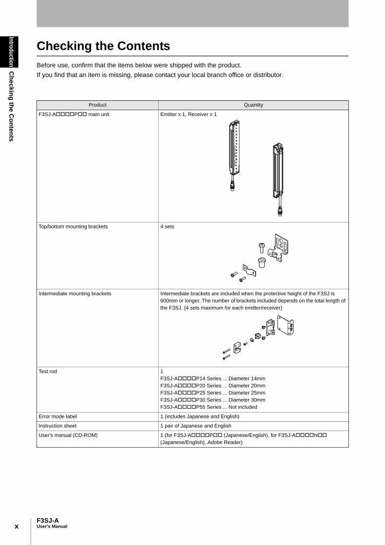
Checking the Contents Before use, confirm that the items below were shipped with the product. If you find that an item is missing, please contact your local branch office or distributor.
Product Quantity
F3SJ-AP main unit Emitter x 1, Receiver x 1
Top/bottom mounting brackets 4 sets
Intermediate mounting brackets Intermediate brackets are included when the protective height of the F3SJ is 600mm or longer. The number of brackets included depends on the total length of the F3SJ. (4 sets maximum for each emitter/receiver)
Test rod 1F3SJ-AP14 Series ... Diameter 14mmF3SJ-AP20 Series ... Diameter 20mmF3SJ-AP25 Series ... Diameter 25mmF3SJ-AP30 Series ... Diameter 30mmF3SJ-AP55 Series ... Not included
Error mode label 1 (includes Japanese and English)
Instruction sheet 1 pair of Japanese and English
User's manual (CD-ROM) 1 (for F3SJ-AP (Japanese/English), for F3SJ-AN (Japanese/English), Adobe Reader)
xiF3SJ-A
User’s Manual
IntroductionH
ow to R
ead This Manual (Explanation of Sym
bols)
E
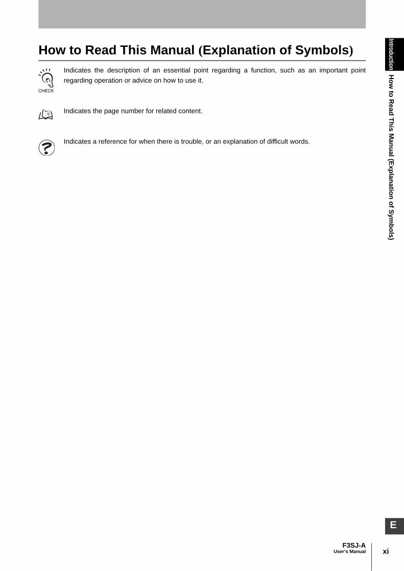
How to Read This Manual (Explanation of Symbols)Indicates the description of an essential point regarding a function, such as an important pointregarding operation or advice on how to use it.
Indicates the page number for related content.
Indicates a reference for when there is trouble, or an explanation of difficult words.

xii
IntroductionH
ow to R
ead This Manual (Explanation of Sym
bols)
F3SJ-AUser’s Manual
xiiiF3SJ-A
User’s Manual
IntroductionC
ontents
E
ContentsLegislation and Standards i
READ AND UNDERSTAND THIS DOCUMENT ii
Precautions on Safety iv
Precautions for Safe Use viii
Precautions for Correct Use viii
Checking the Contents x
How to Read This Manual (Explanation of Symbols) xi
Chapter1 Overview and Specifications 1
Basic Configuration and Names 2
Application Examples 5
Detect the Approach to a Hazardous Zone 5
Using Multiple Sets in Combination 6
For a System in which a Workpiece Crosses Detection Zone (Muting Function) 6
For a System that Has a Machine Within a Detection Zone 7
To Notify a Person of Proximity to a Detection Zone (Warning Zone Function) 8
Features 9
Protective Height Available in Incremental Sizes 9
Easy-to-Read Light Level and Error Mode Display 9
Providing Tools for Setting 9
Additional Safety Functions 9
Enhanced Mutual Interference Prevention 9
Muting/Override Function are Provided 10
Indicator Display Patterns 11
Internal Indicator for Basic System 11
Internal Indicator for Muting System 12
Display Patterns of the Incident Light Level Indicator 13
Ratings 14
Ratings/Specifications 14
Model Name List/Response Times 17
Power Cable Length 22
Compatibility with former version 23
Chapter2 System Configuration and Functions 25
How to Select a System 26
Selection Flow Chart 26
Combination of Functions 26
Basic System 27
Wiring Diagrams 27
xiv
IntroductionC
ontents
F3SJ-AUser’s Manual
Interlock Function 29
External Test Function 31
Self-Test Function 31
Auxiliary Output (Non-Safety Output) 32
Resetting Lockout 33
External Device Monitoring Function 34
Muting System 35
Upgrading F3SJ for Muting System 36
Standard Muting Mode 38
Wiring Diagrams 40
Installation Standard for Muting Sensors 42
Installation Example 1 of Standard Muting Mode (using 2 muting sensors) 42
Installation Example 2 of Standard Muting Mode (using 4 muting sensors) 46
Override Function 52
External Test Function 54
Self-Test Function 54
Auxiliary Output (Non-Safety Output) 55
Resetting Lockout 55
External Device Monitoring Function (EDM) 55
Chapter3 What can be done by the setting tool 57
Using the Setting Tool 58
F3SJ Version 58
List of Functions that Can Be Changed by the Setting Tool 59
Preparation 61
Setting Console 61
PC Tool for F3SJ 61
F3SJ Status When Setting Tool Is Connected 63
Maintenance Status 63
Internal Indicators During Maintenance Status 63
Internal Indicator While Writing/Monitoring with the Setting Tool 64
Protection of Setting by Password 65
Access Qualification 65
Password Change 65
If You Forget the Password: 65
Setting Adjusted to Application 66
Fixed Blanking Function 66
Floating Blanking Function 70
Warning Zone Function 78
Muting Function 81
Override Function 92

xvF3SJ-A
User’s Manual
IntroductionC
ontents
E
Setting Zone Adjacent Conditions 92
Indicator/Input & Output Setting 95
Auxiliary Output (Non-Safety Output) 95
Designated Beam Output Function 97
External Indicator Output (Non-Safety Output) 99
Interlock Function 100
External Device Monitoring Function 102
Operating Range Change 103
Operating Range Change Function 103
Operation Monitoring 104
Incident Light Level Display 104
Disturbance Light Level Display 104
Status Information Display 105
Maintenance Information 106
Error History 106
Power-on Time 106
Load Switching Frequency 108
Setting Recovery 109
Setting Recovery Function 109
Other 110
Safety Distance Calculation Function 110
Connection Cable Length Calculation Function 110
Rated Response Time Check 110
Chapter4 Wiring/Installation 113
Installation Conditions 114
Detection Zone and Approach 114
Safety Distance 115
Distance from Reflective Surfaces 118
Mutual Interference Prevention 119
Series Connection 122
Connection Procedure 124
Attaching External Indicators 126
Connection Procedure 126
Output Operation 127
Setting Change by the Setting Tool 127
Dimensions 128
When Using Standard Mounting Brackets 128
When Using Optional Mounting Brackets 131
F39-A01Po-PAC External Indicator Set 148
When Using Spatter Protection Covers 148
xvi
IntroductionC
ontents
F3SJ-AUser’s Manual
Setting Tool 149
Mounting a Protect Bar 150
Mounting an Environment-Resistant Case 152
Mounting 154
Top/Bottom Mounting Brackets 154
Intermediate Mounting Brackets 154
Mounting Procedure 155
Adjustment Procedure 158
Wiring 159
Wiring Precautions 159
Power Supply Unit 160
Wiring Procedure 161
Chapter5 Input/Output Circuit and Applications 167
Input/Output Circuit 168
Wiring Examples 169
Using only F3SJ 169
Connecting 2 Muting Sensors 170
Connecting 4 Muting Sensors 171
Connecting to an F3SP-B1P 172
Connecting to an F3SX-E-L2R2 173
Connecting to a G9SA-301 175
Connecting to a G9SA-300-SC 176
Connecting to a G9SB-301-D 177
Connecting to a G9SX-AD322-T15 178
Chapter6 Checklists 179
Pre-Operation Checklists 180
Checklists 180
Maintenance Checklists 183
Checklists 183
Chapter7 Appendix 185
Troubleshooting 186
Lockout State 186
Problem under other state than lockout 193
Accessories (Sold Separately) 195
Glossary 203
Related Standards 207
International Standards 207

xviiF3SJ-A
User’s Manual
IntroductionC
ontents
E
European Standards 207
U.S. Federal Regurations 207
U.S. Standards 207
Canadian Standards 208
Revision History 209

xviii
IntroductionC
ontents
F3SJ-AUser’s Manual

Chapter1
Overview
and Specifications
1F3SJ-A
User’s Manual
E
Chapter1 Overview and Specifications
Basic Configuration and Names 2
Application Examples 5
Features 9
Indicator Display Patterns 11
Ratings 14
Ratings/Specifications 14Model Name List/Response Times 17Power Cable Length 22
Compatibility with former version 23

2
Chapter1
Basic C
onfiguration and Nam
es
F3SJ-AUser’s Manual
Overview and Specifications
Basic Configuration and NamesThis section describes the system configuration and part names of the F3SJ.
To distinguish between the emitter and receiver, find the labels attached to the front of the F3SJ. The label on the emitter reads"EMITTER" and the label on the receiver reads "RECEIVER". These words are printed on the side where the power supply connector is located.
Component Model name Description
Emitter, receiver F3SJ-AP Select a model name based on the required protective height and detection capability. (Cap and connection cable are included.)The model name can be understood as follows:
1: Protective height (mm)2: Output type (P=PNPoutput type)3: Detection capability (mm)4: L is emitter, D is receiver, blank is a set of an emitter and a receiver
Emitter
Receiver
Cap
Indicator
Beam
Extension cable
Beam center-line mark
Connection cable (Grey)
Connection cable (Black)
To attach or detach the cap
and power cable,
remove 4 screws shown above.
F3SJ-AP-

3F3SJ-A
User’s Manual
Chapter1
Basic C
onfiguration and Nam
esOverview and Specifications
E
Component Model name Description
Extension cable
Cable with connector on one end
F39-JCA This extension cable is used to connect the F3SJ to a controller with discrete terminals (e.g. F3SX, G9SA, G9SB, G9SX) or to a safety processing system (e.g. DeviceNet safety).
p.195
Cable with connectors on both ends
F39-JCB This extension cable is used when the length of the connection cable is insufficient or for plug and play connection to the F3SP-B1P controller. The length can be selected.
p.195
Cable with connectors on both ends
F39-JCC This connection cable is used for plug and play connection to the G9SA-300-SC controller. The length can be selected.

4
Chapter1
Basic C
onfiguration and Nam
es
F3SJ-AUser’s Manual
Overview and Specifications
Components to be selected if necessaryComponent Model name Description
Optional bracket - Use this bracket (sold separately) for dedicated applications.
p.131
Series connection cable for close contact
F39-JJR06LF39-JJR15L
Required for connecting multiple sets of F3SJ in a series. It is used when you wish to perform series connection with minimum length.
Connection Procedure p.124
Series connection cable for extension
F39-JJR3W Required for connecting multiple sets of F3SJ in a series. The F39- JJR3W can be used for extension with cable with connectors on both ends(F39-JCB).
Connection Procedure p.125
Key cap for muting F39-CN6 Required when using muting function. (Case color : Orange)
Muting System p.35
Indicator cable F39-JJ3N F39-A01P-PAC
Required when attaching external indicator(s) to the F3SJ.
Attaching External Indicators p.126
Setting console F39-MC21 Required to change functional setting or investigate status of F3SJ.
Using the Setting Tool p.58
PC tool for F3SJ F39-GWUM Required to change functional setting or investigate status of F3SJ.
Using the Setting Tool p.58
5F3SJ-A
User’s Manual
Chapter1
Application Exam
plesOverview and Specifications
E
Application Examples
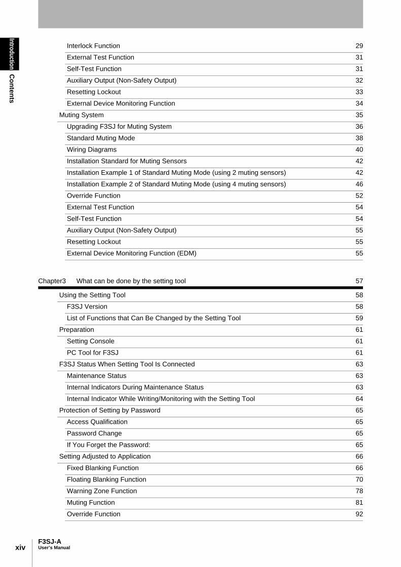
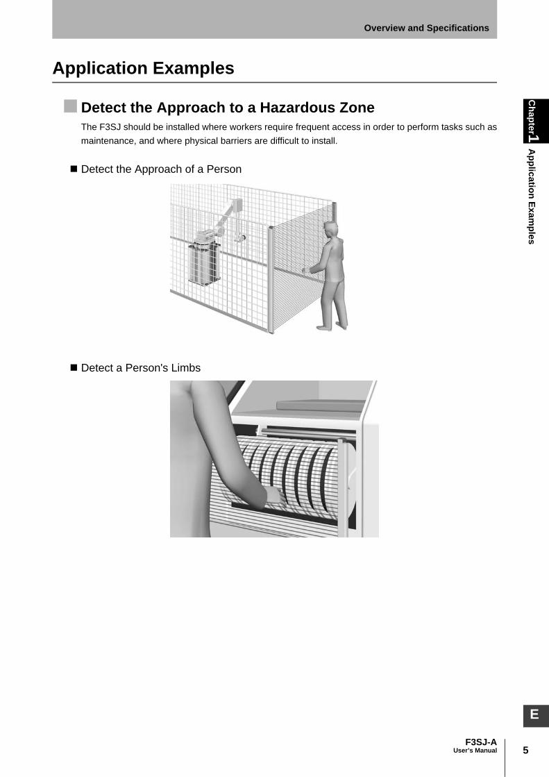
Detect the Approach to a Hazardous ZoneThe F3SJ should be installed where workers require frequent access in order to perform tasks such asmaintenance, and where physical barriers are difficult to install.
Detect the Approach of a Person
Detect a Person's Limbs

6
Chapter1
Application Exam
ples
F3SJ-AUser’s Manual
Overview and Specifications
Using Multiple Sets in CombinationBy installing sensors on both sides of a machine as well as in front, you can move workpieces in andout more efficiently than when a physical barrier is installed. If the sensors are aligned in a U-shape,series-connection cables can be used between sets (up to 4 sets), so that only one control device isused, drastically reducing the amount of wiring in the panel.
For a System in which a Workpiece Crosses Detection Zone (Muting Function)Enter of a workpiece can be detected by a sensor and the detection zone can be temporarily disabledonly while the workpiece is crossing the whole or specified zone. This function is called muting. Muting is when a work piece is allowed to enter into a dangerous zone without tripping the F3SJ andstopping the process. Muting sensors are installed and arranged as to detect the work piece and not ahuman entering the zone.

7F3SJ-A
User’s Manual
Chapter1
Application Exam
plesOverview and Specifications
E
For a System that Has a Machine Within a Detection ZoneWhen the Zone Is Fixed (Fixed Blanking Function):
For a system in which a fixed facility such as a worktable or a conveyor interrupts specific beams, thefixed blanking function can be used to disable the specific beams.
When the Zone Is Movable (Floating Blanking Function):If a part of the machine can move within the detection zone, the floating blanking function can be usedto disable a part of the detection zone.You can configure a number of beams to be interrupted by an object so that the safety function worksonly if more beams than the number are interrupted.
8
Chapter1
Application Exam
ples
F3SJ-AUser’s Manual
Overview and Specifications
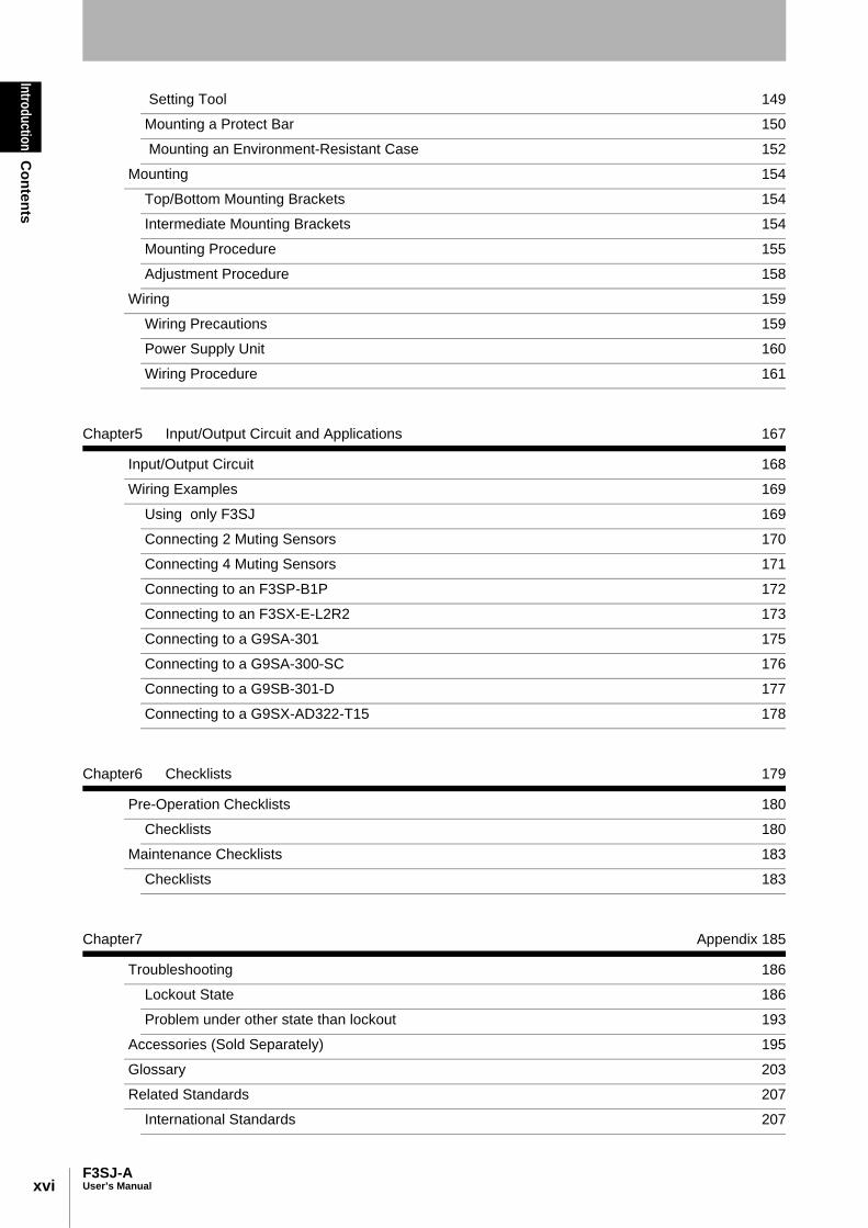
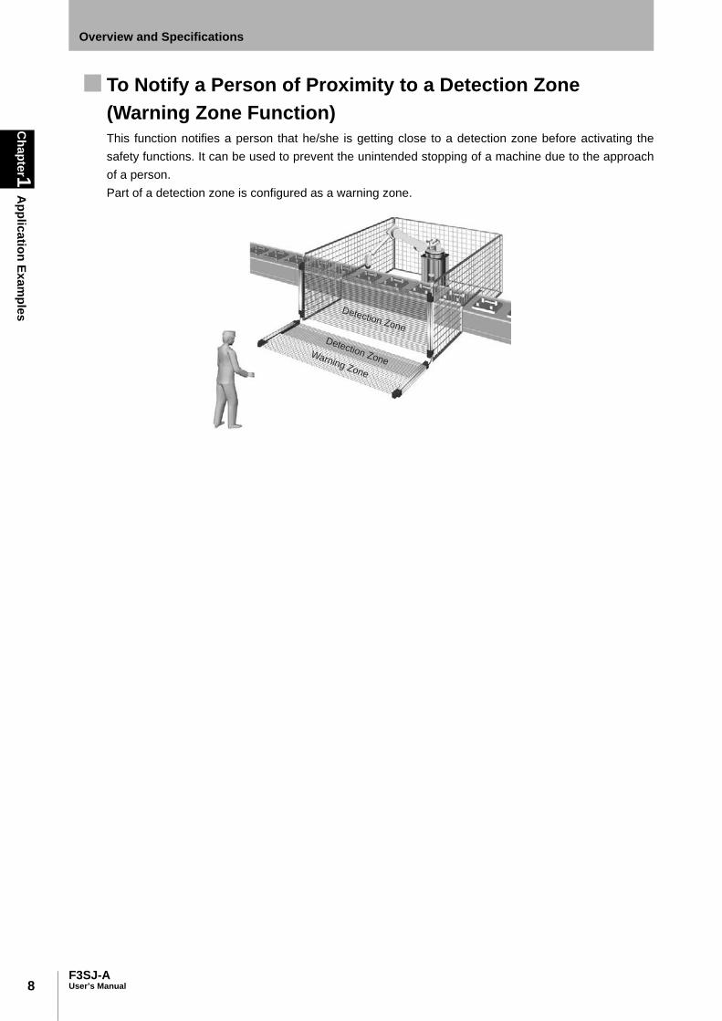
To Notify a Person of Proximity to a Detection Zone (Warning Zone Function)This function notifies a person that he/she is getting close to a detection zone before activating thesafety functions. It can be used to prevent the unintended stopping of a machine due to the approachof a person.Part of a detection zone is configured as a warning zone.
Detection Zone
Detection ZoneWarning Zone

9F3SJ-A
User’s Manual
Chapter1
FeaturesOverview and Specifications
E
Features
Protective Height Available in Incremental Sizes
Easy-to-Read Light Level and Error Mode Display Beam alignment is simplified using 5 LEDs that display the incident lightlevel. Error status is indicated on 3 additional LEDs when an error occurs.
Indicator Display Patterns p.11
Providing Tools for SettingTwo types of tools are provided to change functional setting ofF3SJ. (Accessories sold separately)These tools allow you to change functions or check status of F3SJ,taking more advantage of F3SJ.•Setting Console F39-MC21•PC Tool For F3SJ F39-GWUM
Additional Safety Functions•External test (light emission stop)•External device monitoring function•Interlock function•Fixed/Floating Blanking Function
(Configuration by the setting tool is required)
Enhanced Mutual Interference PreventionWhen the series connection function is used, mutual interference is prevented in up to 400 beams in 4sets.When F3SJ are used individually, the newly designed interference light detection and cycle shiftalgorithm prevents mutual interference in up to 3 sets. The effect of interference between the F3SJ and other photoelectric sensors can be reduced by usingthe setting tool to shorten the operating range.
p.119
Series Protective height Detection capability
F3SJ-AP14 245mm to 2117mm (in 9mm increments) Dia. 14mm
F3SJ-AP20 245mm to 2,495mm (in 15mm increments) Dia. 20mm
F3SJ-AP25 260mm to 2,500mm (in 20mm increments) Dia. 25mm
F3SJ-AP30 245mm to 2,495mm (in 25mm increments) Dia. 30mm
F3SJ-AP55 270mm to 2,470mm (in 50mm increments) Dia. 55mm
Protective height
Incident light
level indicator
Error mode
indicator
LEVEL
5
4
3
2
1
C
B
A

10
Chapter1
Features
F3SJ-AUser’s Manual
Overview and Specifications
Muting/Override Function are ProvidedAn F3SJ by itself can operate with muting or override function without using a controller.
Definition of muting function and override function p.203

11F3SJ-A
User’s Manual
Chapter1
Indicator Display Patterns
Overview and Specifications
E
Indicator Display Patterns
Internal Indicator for Basic SystemShown below are indication statuses of F3SJ's internal indicator when you purchased.
No. IndicatorsON/
BlinkingDescription
1 Incident light level indicator
LEVEL-1 to 5 ON Indication status of LEVEL-1 to 5 shows the incident light level status of the F3SJ.
2 Error mode indicator ERROR-A to C ON/Blinking
Turns ON or blinks only when the F3SJ enters lockout, and the cause of the error is indicated by the status of ERROR-A to C indicators.When F3SJ are series-connected, the error mode indicator lamps turn ON or blink according to the details of each error. Affix the error mode label (included) near the F3SJ to allow for quick troubleshooting when errors occur. For details of the error mode, see "Chapter 7 Troubleshooting".
3 Power indicator POWER ON Turns ON while the power is ON.
Blinking Blinks during maintenance status.
4 Interlock indicator INTLK ON Turns ON when F3SJ is in interlock state.
Blinking Blinks when in lockout.
5 External device monitoring indicator
EDM ON Turns ON when an input is given to external device monitoring input.
6 Blanking/Test indicator BLANKING/TEST
ON Turns ON when the blanking function and warning zone function are enabled.
Blinking Blinks when external test is being performed.
4. Interlock indicator (Yellow)
3. Power indicator (Green)
2. Error mode
indicator
1. Incident light level
indicator
EM
ITT
ER
LEVEL
POWER
ERROR ERROR
INTLK
EDM
Blanking(TEST)
5
4
3
2
1
C
B
A
5
4
3
2
1
C
B
A
RE
CE
IVE
R
LEVEL
OFF
ON
*1
LEVEL-5 (Green)
LEVEL-1 (Orange)
LEVEL-2 (Orange)
LEVEL-3 (Orange)
LEVEL-4 (Green)
ERROR-C (Red)
ERROR-B (Red)
ERROR-A (Red)
LEVEL-1 (Orange)
LEVEL-2 (Orange)
LEVEL-3 (Orange)
LEVEL-4 (Green)
LEVEL-5 (Green)
ERROR-B (Red)
ERROR-A (Red)
ERROR-C (Red)
1. Incident light
level indicator
2. Error mode
indicator
8. ON-state indicator (Green)
7. OFF-state indicator (Red)
Emitter Receiver
5. External device monitoring indicator (Green)
[Muting input 1 indicator]
6. Blanking/Test indicator(Green)
[Muting input 2 indicator]
9. Not used (Green)
[Muting error indicator]
10. Not used (Green)
[Blanking/Test indicator]
A set of square brackets, [ ], indicates
name of an indicator under muting system.
*1 This label comes with the F39-CN6 key
cap for muting. Affix this label when a
keycap is used.
30 30
12
Chapter1
Indicator Display Patterns
F3SJ-AUser’s Manual
Overview and Specifications
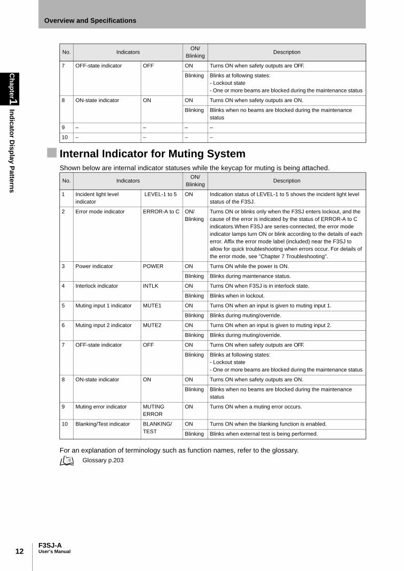
Internal Indicator for Muting SystemShown below are internal indicator statuses while the keycap for muting is being attached.
For an explanation of terminology such as function names, refer to the glossary. Glossary p.203
7 OFF-state indicator OFF ON Turns ON when safety outputs are OFF.
Blinking Blinks at following states:- Lockout state- One or more beams are blocked during the maintenance status
8 ON-state indicator ON ON Turns ON when safety outputs are ON.
Blinking Blinks when no beams are blocked during the maintenance status
9 – – – –
10 – – – –
No. IndicatorsON/
BlinkingDescription
1 Incident light level indicator
LEVEL-1 to 5 ON Indication status of LEVEL-1 to 5 shows the incident light level status of the F3SJ.
2 Error mode indicator ERROR-A to C ON/Blinking
Turns ON or blinks only when the F3SJ enters lockout, and the cause of the error is indicated by the status of ERROR-A to C indicators.When F3SJ are series-connected, the error mode indicator lamps turn ON or blink according to the details of each error. Affix the error mode label (included) near the F3SJ to allow for quick troubleshooting when errors occur. For details of the error mode, see "Chapter 7 Troubleshooting".
3 Power indicator POWER ON Turns ON while the power is ON.
Blinking Blinks during maintenance status.
4 Interlock indicator INTLK ON Turns ON when F3SJ is in interlock state.
Blinking Blinks when in lockout.
5 Muting input 1 indicator MUTE1 ON Turns ON when an input is given to muting input 1.
Blinking Blinks during muting/override.
6 Muting input 2 indicator MUTE2 ON Turns ON when an input is given to muting input 2.
Blinking Blinks during muting/override.
7 OFF-state indicator OFF ON Turns ON when safety outputs are OFF.
Blinking Blinks at following states:- Lockout state- One or more beams are blocked during the maintenance status
8 ON-state indicator ON ON Turns ON when safety outputs are ON.
Blinking Blinks when no beams are blocked during the maintenance status
9 Muting error indicator MUTING ERROR
ON Turns ON when a muting error occurs.
10 Blanking/Test indicator BLANKING/TEST
ON Turns ON when the blanking function is enabled.
Blinking Blinks when external test is being performed.
No. IndicatorsON/
BlinkingDescription

13F3SJ-A
User’s Manual
Chapter1
Indicator Display Patterns
Overview and Specifications
E
Display Patterns of the Incident Light Level Indicator
Operation is possible with incident light level of 100% or more, but to ensure stability, operate when all incident lightlevel indicators
incident light level indicator
Safety Output ON ON ON OFF OFF OFF
Incident light level170% or higher
Less than 170%~130%
Less than 130%~
100%
Less than 100%~
75%
Less than 75%~
50%
Less than 50%
ON OFF
5
4
3
2
1
5
4
3
2
1
5
4
3
2
1
5
4
3
2
1
5
4
3
2
1
5
4
3
2
1

14
Chapter1
Ratings
F3SJ-AUser’s Manual
Overview and Specifications
Ratings
Ratings/SpecificationsIn the model names in this table, the contain the 4-digit number indicating the protective height(mm).
F3SJ-AP14
F3SJ-AP20
F3SJ-AP25
F3SJ-AP30
F3SJ-AP55
Detection capability Opaque objects Opaque objects Opaque objects Opaque objects Opaque objects
Diameter 14mm Diameter 20mm Diameter 25mm Diameter 30mm Diameter 55mm
Beam gap 9mm 15mm 20mm 25mm 50mm
Number of beams 26 to 234 16 to 166 13 to 125 10 to 100 6 to 50
Protective height 245 to 2,117mm 245 to 2,495mm 260 to 2,500mm 245 to 2,495mm 270 to 2,470mm
Lens diameter Diameter 5mm
Operating range 0.2 to 9m (for protective height up to 1649 mm)0.2 to 7m (for protective height 1655 mm or greater)(Operating range can be reduced to 0.5m through the setting tool)
Response time ON to OFF: 10ms to 27.5ms max., OFF to ON: 40ms to 110ms max. (when incidence is stable). Refer to p.17 for details.
Startup waiting time 2s max. (2.2s max in case of series connection)
Power supply voltage(Vs) 24VDC ± 20% (ripple p-p10% max.)
Current consumption (no load)
Emitter Up to 50 beams: 76 mA max., 51 to 100 beams: 106 mA max., 101 to 150 beams: 130 mA max., 151 to 200 beams: 153 mA max., 201 to 234 beams: 165 mA max.
Receiver Up to 50 beams: 68 mA max., 51 to 100 beams: 90 mA max., 101 to 150 beams: 111 mA max., 151 to 200 beams: 128 mA max., 201 to 234 beams: 142 mA max.
Light source Infrared LED (870nm wavelength)
Effective aperture angle (EAA) Within ±2.5 ° for the emitter and receiver at a detection distance of at least 3 m according to IEC61496-2
Safety outputs(OSSD) PNP transistor outputs x 2, Load current 300mA max, Residual voltage 2V max. (except for voltage drop due to cable extension)(including inductance load), Maximum capacity load 2.2 F, leakage current 1 mA max. (This may be different from previously used logic (ON/OFF) because safety circuit is used.)
Auxiliary output 1 (Non-safety output) PNP transistor output x 1, Load current 300mA max., Residual voltage 2V max. (except for voltage drop due to cable extension), leakage current 1mA max.
Auxiliary output 2 (non-safety output, a function for a basic system)
PNP transistor output x 1, load current 50mA or less, residual voltage 2V or less (excluding influence by cable extension), leakage current 1mA or less
External indicator output (Non-safety output)
Connectable external indicator - Incandescent lamp : 24VDC, 3 to 7W- LED lamp : Load current 10 to 300mA max. Leakage current 1mA max. (An indicator cable F39-JJ3N or F39-A01P-PAC is required when using an external indicator.)
Output operation mode Safety outputs : ON when receiving light Auxiliary output 1 : Reverse output of safety output (operation mode can be changed by the setting tool)Auxiliary output 2: Turns ON when 30,000 hours of power-on time passes (operation mode can be changed by the setting tool)External indicator output 1: Reverse output of safety output (for basic system), ON during muting/override (for muting system) (Operation mode can be changed by the setting tool)External indicator output 2: ON in lockout (for basic system), ON during muting/override (for muting system) (operation mode can be changed by the setting tool)

15F3SJ-A
User’s Manual
Chapter1
Ratings
Overview and Specifications
E
Input voltage Test input, interlock selection input, reset input, and muting input are all:ON voltage: 9 to 24Vs (sink current 3mA max.)OFF voltage: 0 to 1.5V , or openExternal device monitoring input is:ON voltage: 9 to 24Vs (sink current 5mA max.)OFF voltage: 0 to 1.5V , or open
Indicators Emitter Incident light level indicators (green LED x 2, orange LED x 3): ON based on the amount of incident light Error mode indicators (red LED x 3): Blink to indicate error details Power indicator (green LED x 1): ON while power is ON Interlock indicator (yellow LED x 1): ON when in interlock/Blinks when in lockout External device monitoring indicator (muting input 1 indicator), Blanking/ Test indicator (muting input 2 indicator) (green LED x2): ON/Blink according to function
Receiver Incident light level indicators (green LED x 2, orange LED x 3): ON based on the amount of incident light Error mode indicators (red LED x 3): Blink to indicate error details OFF-statet indicator (red LED x 1): ON when safety outputs are OFF/ Blinks when in lockout ON-state indicator (green LED x 1): ON when safety outputs are ON Muting error indicator, Blanking/Test indicator (green LED x 2): ON/Blink according to function
Mutual interference prevention function
Interference light avoidance algorithm, operating range change function
Series connection Time division emission by series connection - Number of connections: Up to 4 sets - Total number of beams: Up to 400 - Maximum cable length between 2 sets of sensors: 15m
Test function - Self-test (After power ON, and during operation) - External test (light emission stop function by test input)
Safety-related functions - Start interlock, restart interlock (The setting tool is required when muting function is used) - External device monitoring - Muting (Includes lamp breakage detection and override functions. F39-CN6 key cap for muting is required) - Fixed blanking (configuration by the setting tool is required)- Floating blanking (configuration by the setting tool is required)
Connection method Connector method (M12, 8-pin)
Protection circuit Output short-circuit protection, and power supply reverse polarity protection
Ambient temperature During operation: -10 to 55°C (without freezing), During storage: -30 to 70°C
Ambient humidity During operation: 35 to 85%RH (no condensation), During storage: 35 to 95%RH
Ambient light intensity Incandescent lamp: receiving-surface light intensity of 3,000 Ix max., Sunlight: receiving-surface light intensity of 10,000 Ix max.
Insulation resistance 20M or higher (500VDC)
Dielectric strength voltage 1, 000VAC, 50/60Hz, 1min
Degree of protection IP65 (IEC60529)
Vibration resistance Malfunction: 10 to 55Hz, Multiple amplitude of 0.7mm, 20 sweeps each in X, Y, and Z directions
Shock resistance Malfunction: 100m/s2, 1,000 times each in X, Y, and Z directions
Connection cable, Series connection cable (F39-JJRL, JJR3W)
Dia. 6 mm, 8-wire (0.15mm2 x 8) with braided shield, Allowable bending radius R5mm
Extension cable (F39-JCA, JCB,JCC)
Dia. 6.6 mm, 8-wire (0.3mm2 x 4P, conductor resistance 0.058 ohm/m), with braided shield, Allowable bending radius of R36mm.(To extend a cable, use an equivalent or higher-performance cable (twisted-pair wire) , and do not use the cable in the same duct as that for high-voltage cables or power cables)
For details about extension lengths (power cable length) p.22
For details about twisted pair wire (single connector cable) p.161
F3SJ-AP14
F3SJ-AP20
F3SJ-AP25
F3SJ-AP30
F3SJ-AP55
16
Chapter1
Ratings
F3SJ-AUser’s Manual
Overview and Specifications
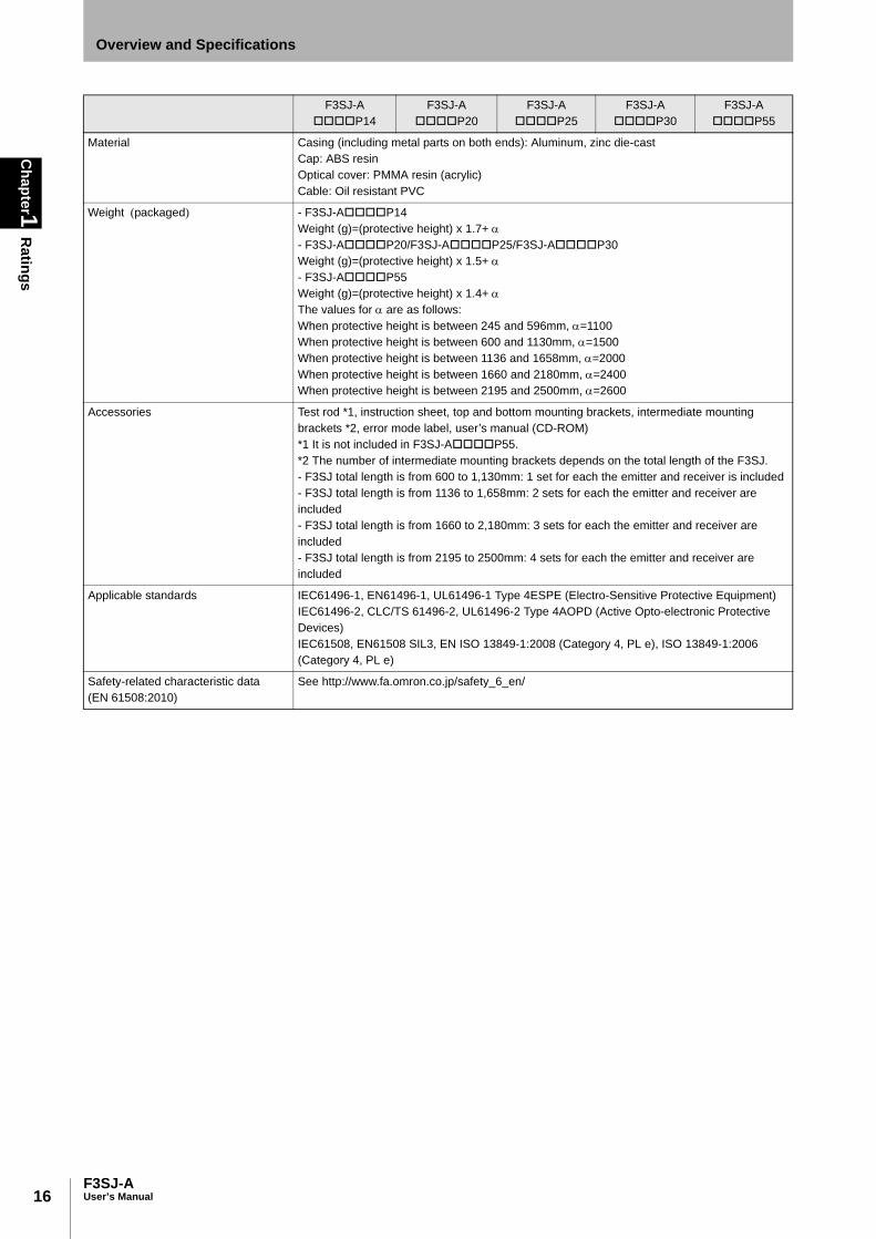
Material Casing (including metal parts on both ends): Aluminum, zinc die-cast Cap: ABS resin Optical cover: PMMA resin (acrylic) Cable: Oil resistant PVC
Weight (packaged) - F3SJ-AP14Weight (g)=(protective height) x 1.7+ - F3SJ-AP20/F3SJ-AP25/F3SJ-AP30Weight (g)=(protective height) x 1.5+ - F3SJ-AP55Weight (g)=(protective height) x 1.4+ The values for are as follows: When protective height is between 245 and 596mm, =1100When protective height is between 600 and 1130mm, =1500When protective height is between 1136 and 1658mm, =2000When protective height is between 1660 and 2180mm, =2400When protective height is between 2195 and 2500mm, =2600
Accessories Test rod *1, instruction sheet, top and bottom mounting brackets, intermediate mounting brackets *2, error mode label, user’s manual (CD-ROM) *1 It is not included in F3SJ-AP55.*2 The number of intermediate mounting brackets depends on the total length of the F3SJ. - F3SJ total length is from 600 to 1,130mm: 1 set for each the emitter and receiver is included- F3SJ total length is from 1136 to 1,658mm: 2 sets for each the emitter and receiver are included- F3SJ total length is from 1660 to 2,180mm: 3 sets for each the emitter and receiver are included- F3SJ total length is from 2195 to 2500mm: 4 sets for each the emitter and receiver are included
Applicable standards IEC61496-1, EN61496-1, UL61496-1 Type 4ESPE (Electro-Sensitive Protective Equipment)IEC61496-2, CLC/TS 61496-2, UL61496-2 Type 4AOPD (Active Opto-electronic Protective Devices)IEC61508, EN61508 SIL3, EN ISO 13849-1:2008 (Category 4, PL e), ISO 13849-1:2006 (Category 4, PL e)
Safety-related characteristic data (EN 61508:2010)
See http://www.fa.omron.co.jp/safety_6_en/
F3SJ-AP14
F3SJ-AP20
F3SJ-AP25
F3SJ-AP30
F3SJ-AP55

17F3SJ-A
User’s Manual
Chapter1
Ratings
Overview and Specifications
E
Model Name List/Response Times
F3SJ-AP14
F3SJ-AP20
F3SJ-AP25
F3SJ-AP30
F3SJ-AP55
Number of beams
Response time
(ON to OFF)
Response time
(OFF to ON)
- - - - F3SJ-A0270P55 6 beams 10ms 40ms
- - - - F3SJ-A0320P55 7 beams 10ms 40ms
- - - - F3SJ-A0370P55 8 beams 10ms 40ms
- - - - F3SJ-A0420P55 9 beams 10ms 40ms
- - - F3SJ-A0245P30 F3SJ-A0470P55 10 beams 10ms 40ms
- - - F3SJ-A0270P30 F3SJ-A0520P55 11 beams 10ms 40ms
- - - F3SJ-A0295P30 F3SJ-A0570P55 12 beams 10ms 40ms
- - F3SJ-A0260P25 F3SJ-A0320P30 F3SJ-A0620P55 13 beams 10ms 40ms
- - F3SJ-A0280P25 F3SJ-A0345P30 F3SJ-A0670P55 14 beams 10ms 40ms
- - F3SJ-A0300P25 F3SJ-A0370P30 F3SJ-A0720P55 15 beams 10ms 40ms
- F3SJ-A0245P20 F3SJ-A0320P25 F3SJ-A0395P30 F3SJ-A0770P55 16 beams 10ms 40ms
- F3SJ-A0260P20 F3SJ-A0340P25 F3SJ-A0420P30 F3SJ-A0820P55 17 beams 11ms 44ms
- F3SJ-A0275P20 F3SJ-A0360P25 F3SJ-A0445P30 F3SJ-A0870P55 18 beams 11ms 44ms
- F3SJ-A0290P20 F3SJ-A0380P25 F3SJ-A0470P30 F3SJ-A0920P55 19 beams 11ms 44ms
- F3SJ-A0305P20 F3SJ-A0400P25 F3SJ-A0495P30 F3SJ-A0970P55 20 beams 11ms 44ms
- F3SJ-A0320P20 F3SJ-A0420P25 F3SJ-A0520P30 F3SJ-A1020P55 21 beams 11ms 44ms
- F3SJ-A0335P20 F3SJ-A0440P25 F3SJ-A0545P30 F3SJ-A1070P55 22 beams 11ms 44ms
- F3SJ-A0350P20 F3SJ-A0460P25 F3SJ-A0570P30 F3SJ-A1120P55 23 beams 11ms 44ms
- F3SJ-A0365P20 F3SJ-A0480P25 F3SJ-A0595P30 F3SJ-A1170P55 24 beams 11ms 44ms
- F3SJ-A0380P20 F3SJ-A0500P25 F3SJ-A0620P30 F3SJ-A1220P55 25 beams 11ms 44ms
F3SJ-A0245P14 F3SJ-A0395P20 F3SJ-A0520P25 F3SJ-A0645P30 F3SJ-A1270P55 26 beams 11ms 44ms
F3SJ-A0254P14 F3SJ-A0410P20 F3SJ-A0540P25 F3SJ-A0670P30 F3SJ-A1320P55 27 beams 11ms 44ms
F3SJ-A0263P14 F3SJ-A0425P20 F3SJ-A0560P25 F3SJ-A0695P30 F3SJ-A1370P55 28 beams 11ms 44ms
F3SJ-A0272P14 F3SJ-A0440P20 F3SJ-A0580P25 F3SJ-A0720P30 F3SJ-A1420P55 29 beams 11ms 44ms
F3SJ-A0281P14 F3SJ-A0455P20 F3SJ-A0600P25 F3SJ-A0745P30 F3SJ-A1470P55 30 beams 12ms 48ms
F3SJ-A0290P14 F3SJ-A0470P20 F3SJ-A0620P25 F3SJ-A0770P30 F3SJ-A1520P55 31 beams 12ms 48ms
F3SJ-A0299P14 F3SJ-A0485P20 F3SJ-A0640P25 F3SJ-A0795P30 F3SJ-A1570P55 32 beams 12ms 48ms
F3SJ-A0308P14 F3SJ-A0500P20 F3SJ-A0660P25 F3SJ-A0820P30 F3SJ-A1620P55 33 beams 12ms 48ms
F3SJ-A0317P14 F3SJ-A0515P20 F3SJ-A0680P25 F3SJ-A0845P30 F3SJ-A1670P55 34 beams 12ms 48ms
F3SJ-A0326P14 F3SJ-A0530P20 F3SJ-A0700P25 F3SJ-A0870P30 F3SJ-A1720P55 35 beams 12ms 48ms
F3SJ-A0335P14 F3SJ-A0545P20 F3SJ-A0720P25 F3SJ-A0895P30 F3SJ-A1770P55 36 beams 12ms 48ms
F3SJ-A0344P14 F3SJ-A0560P20 F3SJ-A0740P25 F3SJ-A0920P30 F3SJ-A1820P55 37 beams 12ms 48ms
F3SJ-A0353P14 F3SJ-A0575P20 F3SJ-A0760P25 F3SJ-A0945P30 F3SJ-A1870P55 38 beams 12ms 48ms
F3SJ-A0362P14 F3SJ-A0590P20 F3SJ-A0780P25 F3SJ-A0970P30 F3SJ-A1920P55 39 beams 12ms 48ms
F3SJ-A0371P14 F3SJ-A0605P20 F3SJ-A0800P25 F3SJ-A0995P30 F3SJ-A1970P55 40 beams 12ms 48ms
F3SJ-A0380P14 F3SJ-A0620P20 F3SJ-A0820P25 F3SJ-A1020P30 F3SJ-A2020P55 41 beams 12ms 48ms
F3SJ-A0389P14 F3SJ-A0635P20 F3SJ-A0840P25 F3SJ-A1045P30 F3SJ-A2070P55 42 beams 12ms 48ms
F3SJ-A0398P14 F3SJ-A0650P20 F3SJ-A0860P25 F3SJ-A1070P30 F3SJ-A2120P55 43 beams 13ms 52ms
F3SJ-A0407P14 F3SJ-A0665P20 F3SJ-A0880P25 F3SJ-A1095P30 F3SJ-A2170P55 44 beams 13ms 52ms
F3SJ-A0416P14 F3SJ-A0680P20 F3SJ-A0900P25 F3SJ-A1120P30 F3SJ-A2220P55 45 beams 13ms 52ms
F3SJ-A0425P14 F3SJ-A0695P20 F3SJ-A0920P25 F3SJ-A1145P30 F3SJ-A2270P55 46 beams 13ms 52ms
F3SJ-A0434P14 F3SJ-A0710P20 F3SJ-A0940P25 F3SJ-A1170P30 F3SJ-A2320P55 47 beams 13ms 52ms
F3SJ-A0443P14 F3SJ-A0725P20 F3SJ-A0960P25 F3SJ-A1195P30 F3SJ-A2370P55 48 beams 13ms 52ms
F3SJ-A0452P14 F3SJ-A0740P20 F3SJ-A0980P25 F3SJ-A1220P30 F3SJ-A2420P55 49 beams 13ms 52ms

18
Chapter1
Ratings
F3SJ-AUser’s Manual
Overview and Specifications
F3SJ-A0461P14 F3SJ-A0755P20 F3SJ-A1000P25 F3SJ-A1245P30 F3SJ-A2470P55 50 beams 13ms 52ms
F3SJ-A0470P14 F3SJ-A0770P20 F3SJ-A1020P25 F3SJ-A1270P30 - 51 beams 13ms 52ms
F3SJ-A0479P14 F3SJ-A0785P20 F3SJ-A1040P25 F3SJ-A1295P30 - 52 beams 13ms 52ms
F3SJ-A0488P14 F3SJ-A0800P20 F3SJ-A1060P25 F3SJ-A1320P30 - 53 beams 13ms 52ms
F3SJ-A0497P14 F3SJ-A0815P20 F3SJ-A1080P25 F3SJ-A1345P30 - 54 beams 13ms 52ms
F3SJ-A0506P14 F3SJ-A0830P20 F3SJ-A1100P25 F3SJ-A1370P30 - 55 beams 13ms 52ms
F3SJ-A0515P14 F3SJ-A0845P20 F3SJ-A1120P25 F3SJ-A1395P30 - 56 beams 14ms 56ms
F3SJ-A0524P14 F3SJ-A0860P20 F3SJ-A1140P25 F3SJ-A1420P30 - 57 beams 14ms 56ms
F3SJ-A0533P14 F3SJ-A0875P20 F3SJ-A1160P25 F3SJ-A1445P30 - 58 beams 14ms 56ms
F3SJ-A0542P14 F3SJ-A0890P20 F3SJ-A1180P25 F3SJ-A1470P30 - 59 beams 14ms 56ms
F3SJ-A0551P14 F3SJ-A0905P20 F3SJ-A1200P25 F3SJ-A1495P30 - 60 beams 14ms 56ms
F3SJ-A0560P14 F3SJ-A0920P20 F3SJ-A1220P25 F3SJ-A1520P30 - 61 beams 14ms 56ms
F3SJ-A0569P14 F3SJ-A0935P20 F3SJ-A1240P25 F3SJ-A1545P30 - 62 beams 14ms 56ms
F3SJ-A0578P14 F3SJ-A0950P20 F3SJ-A1260P25 F3SJ-A1570P30 - 63 beams 14ms 56ms
F3SJ-A0587P14 F3SJ-A0965P20 F3SJ-A1280P25 F3SJ-A1595P30 - 64 beams 14ms 56ms
F3SJ-A0596P14 F3SJ-A0980P20 F3SJ-A1300P25 F3SJ-A1620P30 - 65 beams 14ms 56ms
F3SJ-A0605P14 F3SJ-A0995P20 F3SJ-A1320P25 F3SJ-A1645P30 - 66 beams 14ms 56ms
F3SJ-A0614P14 F3SJ-A1010P20 F3SJ-A1340P25 F3SJ-A1670P30 - 67 beams 14ms 56ms
F3SJ-A0623P14 F3SJ-A1025P20 F3SJ-A1360P25 F3SJ-A1695P30 - 68 beams 15ms 60ms
F3SJ-A0632P14 F3SJ-A1040P20 F3SJ-A1380P25 F3SJ-A1720P30 - 69 beams 15ms 60ms
F3SJ-A0641P14 F3SJ-A1055P20 F3SJ-A1400P25 F3SJ-A1745P30 - 70 beams 15ms 60ms
F3SJ-A0650P14 F3SJ-A1070P20 F3SJ-A1420P25 F3SJ-A1770P30 - 71 beams 15ms 60ms
F3SJ-A0659P14 F3SJ-A1085P20 F3SJ-A1440P25 F3SJ-A1795P30 - 72 beams 15ms 60ms
F3SJ-A0668P14 F3SJ-A1100P20 F3SJ-A1460P25 F3SJ-A1820P30 - 73 beams 15ms 60ms
F3SJ-A0677P14 F3SJ-A1115P20 F3SJ-A1480P25 F3SJ-A1845P30 - 74 beams 15ms 60ms
F3SJ-A0686P14 F3SJ-A1130P20 F3SJ-A1500P25 F3SJ-A1870P30 - 75 beams 15ms 60ms
F3SJ-A0695P14 F3SJ-A1145P20 F3SJ-A1520P25 F3SJ-A1895P30 - 76 beams 15ms 60ms
F3SJ-A0704P14 F3SJ-A1160P20 F3SJ-A1540P25 F3SJ-A1920P30 - 77 beams 15ms 60ms
F3SJ-A0713P14 F3SJ-A1175P20 F3SJ-A1560P25 F3SJ-A1945P30 - 78 beams 15ms 60ms
F3SJ-A0722P14 F3SJ-A1190P20 F3SJ-A1580P25 F3SJ-A1970P30 - 79 beams 15ms 60ms
F3SJ-A0731P14 F3SJ-A1205P20 F3SJ-A1600P25 F3SJ-A1995P30 - 80 beams 15ms 60ms
F3SJ-A0740P14 F3SJ-A1220P20 F3SJ-A1620P25 F3SJ-A2020P30 - 81 beams 17.5ms 70ms
F3SJ-A0749P14 F3SJ-A1235P20 F3SJ-A1640P25 F3SJ-A2045P30 - 82 beams 17.5ms 70ms
F3SJ-A0758P14 F3SJ-A1250P20 F3SJ-A1660P25 F3SJ-A2070P30 - 83 beams 17.5ms 70ms
F3SJ-A0767P14 F3SJ-A1265P20 F3SJ-A1680P25 F3SJ-A2095P30 - 84 beams 17.5ms 70ms
F3SJ-A0776P14 F3SJ-A1280P20 F3SJ-A1700P25 F3SJ-A2120P30 - 85 beams 17.5ms 70ms
F3SJ-A0785P14 F3SJ-A1295P20 F3SJ-A1720P25 F3SJ-A2145P30 - 86 beams 17.5ms 70ms
F3SJ-A0794P14 F3SJ-A1310P20 F3SJ-A1740P25 F3SJ-A2170P30 - 87 beams 17.5ms 70ms
F3SJ-A0803P14 F3SJ-A1325P20 F3SJ-A1760P25 F3SJ-A2195P30 - 88 beams 17.5ms 70ms
F3SJ-A0812P14 F3SJ-A1340P20 F3SJ-A1780P25 F3SJ-A2220P30 - 89 beams 17.5ms 70ms
F3SJ-A0821P14 F3SJ-A1355P20 F3SJ-A1800P25 F3SJ-A2245P30 - 90 beams 17.5ms 70ms
F3SJ-A0830P14 F3SJ-A1370P20 F3SJ-A1820P25 F3SJ-A2270P30 - 91 beams 17.5ms 70ms
F3SJ-A0839P14 F3SJ-A1385P20 F3SJ-A1840P25 F3SJ-A2295P30 - 92 beams 17.5ms 70ms
F3SJ-A0848P14 F3SJ-A1400P20 F3SJ-A1860P25 F3SJ-A2320P30 - 93 beams 17.5ms 70ms
F3SJ-A0857P14 F3SJ-A1415P20 F3SJ-A1880P25 F3SJ-A2345P30 - 94 beams 17.5ms 70ms
F3SJ-A0866P14 F3SJ-A1430P20 F3SJ-A1900P25 F3SJ-A2370P30 - 95 beams 17.5ms 70ms
F3SJ-A0875P14 F3SJ-A1445P20 F3SJ-A1920P25 F3SJ-A2395P30 - 96 beams 17.5ms 70ms
F3SJ-AP14
F3SJ-AP20
F3SJ-AP25
F3SJ-AP30
F3SJ-AP55
Number of beams
Response time
(ON to OFF)
Response time
(OFF to ON)

19F3SJ-A
User’s Manual
Chapter1
Ratings
Overview and Specifications
E
F3SJ-A0884P14 F3SJ-A1460P20 F3SJ-A1940P25 F3SJ-A2420P30 - 97 beams 17.5ms 70ms
F3SJ-A0893P14 F3SJ-A1475P20 F3SJ-A1960P25 F3SJ-A2445P30 - 98 beams 17.5ms 70ms
F3SJ-A0902P14 F3SJ-A1490P20 F3SJ-A1980P25 F3SJ-A2470P30 - 99 beams 17.5ms 70ms
F3SJ-A0911P14 F3SJ-A1505P20 F3SJ-A2000P25 F3SJ-A2495P30 - 100 beams 17.5ms 70ms
F3SJ-A0920P14 F3SJ-A1520P20 F3SJ-A2020P25 - - 101 beams 17.5ms 70ms
F3SJ-A0929P14 F3SJ-A1535P20 F3SJ-A2040P25 - - 102 beams 17.5ms 70ms
F3SJ-A0938P14 F3SJ-A1550P20 F3SJ-A2060P25 - - 103 beams 17.5ms 70ms
F3SJ-A0947P14 F3SJ-A1565P20 F3SJ-A2080P25 - - 104 beams 17.5ms 70ms
F3SJ-A0956P14 F3SJ-A1580P20 F3SJ-A2100P25 - - 105 beams 17.5ms 70ms
F3SJ-A0965P14 F3SJ-A1595P20 F3SJ-A2120P25 - - 106 beams 17.5ms 70ms
F3SJ-A0974P14 F3SJ-A1610P20 F3SJ-A2140P25 - - 107 beams 17.5ms 70ms
F3SJ-A0983P14 F3SJ-A1625P20 F3SJ-A2160P25 - - 108 beams 17.5ms 70ms
F3SJ-A0992P14 F3SJ-A1640P20 F3SJ-A2180P25 - - 109 beams 17.5ms 70ms
F3SJ-A1001P14 F3SJ-A1655P20 F3SJ-A2200P25 - - 110 beams 17.5ms 70ms
F3SJ-A1010P14 F3SJ-A1670P20 F3SJ-A2220P25 - - 111 beams 17.5ms 70ms
F3SJ-A1019P14 F3SJ-A1685P20 F3SJ-A2240P25 - - 112 beams 17.5ms 70ms
F3SJ-A1028P14 F3SJ-A1700P20 F3SJ-A2260P25 - - 113 beams 20.0ms 80ms
F3SJ-A1037P14 F3SJ-A1715P20 F3SJ-A2280P25 - - 114 beams 20.0ms 80ms
F3SJ-A1046P14 F3SJ-A1730P20 F3SJ-A2300P25 - - 115 beams 20.0ms 80ms
F3SJ-A1055P14 F3SJ-A1745P20 F3SJ-A2320P25 - - 116 beams 20.0ms 80ms
F3SJ-A1064P14 F3SJ-A1760P20 F3SJ-A2340P25 - - 117 beams 20.0ms 80ms
F3SJ-A1073P14 F3SJ-A1775P20 F3SJ-A2360P25 - - 118 beams 20.0ms 80ms
F3SJ-A1082P14 F3SJ-A1790P20 F3SJ-A2380P25 - - 119 beams 20.0ms 80ms
F3SJ-A1091P14 F3SJ-A1805P20 F3SJ-A2400P25 - - 120 beams 20.0ms 80ms
F3SJ-A1100P14 F3SJ-A1820P20 F3SJ-A2420P25 - - 121 beams 20.0ms 80ms
F3SJ-A1109P14 F3SJ-A1835P20 F3SJ-A2440P25 - - 122 beams 20.0ms 80ms
F3SJ-A1118P14 F3SJ-A1850P20 F3SJ-A2460P25 - - 123 beams 20.0ms 80ms
F3SJ-A1127P14 F3SJ-A1865P20 F3SJ-A2480P25 - - 124 beams 20.0ms 80ms
F3SJ-A1136P14 F3SJ-A1880P20 F3SJ-A2500P25 - - 125 beams 20.0ms 80ms
F3SJ-A1145P14 F3SJ-A1895P20 - - - 126 beams 20.0ms 80ms
F3SJ-A1154P14 F3SJ-A1910P20 - - - 127 beams 20.0ms 80ms
F3SJ-A1163P14 F3SJ-A1925P20 - - - 128 beams 20.0ms 80ms
F3SJ-A1172P14 F3SJ-A1940P20 - - - 129 beams 20.0ms 80ms
F3SJ-A1181P14 F3SJ-A1955P20 - - - 130 beams 20.0ms 80ms
F3SJ-A1190P14 F3SJ-A1970P20 - - - 131 beams 20.0ms 80ms
F3SJ-A1199P14 F3SJ-A1985P20 - - - 132 beams 20.0ms 80ms
F3SJ-A1208P14 F3SJ-A2000P20 - - - 133 beams 20.0ms 80ms
F3SJ-A1217P14 F3SJ-A2015P20 - - - 134 beams 20.0ms 80ms
F3SJ-A1226P14 F3SJ-A2030P20 - - - 135 beams 20.0ms 80ms
F3SJ-A1235P14 F3SJ-A2045P20 - - - 136 beams 20.0ms 80ms
F3SJ-A1244P14 F3SJ-A2060P20 - - - 137 beams 20.0ms 80ms
F3SJ-A1253P14 F3SJ-A2075P20 - - - 138 beams 20.0ms 80ms
F3SJ-A1262P14 F3SJ-A2090P20 - - - 139 beams 20.0ms 80ms
F3SJ-A1271P14 F3SJ-A2105P20 - - - 140 beams 20.0ms 80ms
F3SJ-A1280P14 F3SJ-A2120P20 - - - 141 beams 20.0ms 80ms
F3SJ-A1289P14 F3SJ-A2135P20 - - - 142 beams 20.0ms 80ms
F3SJ-A1298P14 F3SJ-A2150P20 - - - 143 beams 20.0ms 80ms
F3SJ-AP14
F3SJ-AP20
F3SJ-AP25
F3SJ-AP30
F3SJ-AP55
Number of beams
Response time
(ON to OFF)
Response time
(OFF to ON)

20
Chapter1
Ratings
F3SJ-AUser’s Manual
Overview and Specifications
F3SJ-A1307P14 F3SJ-A2165P20 - - - 144 beams 20.0ms 80ms
F3SJ-A1316P14 F3SJ-A2180P20 - - - 145 beams 22.5ms 90ms
F3SJ-A1325P14 F3SJ-A2195P20 - - - 146 beams 22.5ms 90ms
F3SJ-A1334P14 F3SJ-A2210P20 - - - 147 beams 22.5ms 90ms
F3SJ-A1343P14 F3SJ-A2225P20 - - - 148 beams 22.5ms 90ms
F3SJ-A1352P14 F3SJ-A2240P20 - - - 149 beams 22.5ms 90ms
F3SJ-A1361P14 F3SJ-A2255P20 - - - 150 beams 22.5ms 90ms
F3SJ-A1370P14 F3SJ-A2270P20 - - - 151 beams 22.5ms 90ms
F3SJ-A1379P14 F3SJ-A2285P20 - - - 152 beams 22.5ms 90ms
F3SJ-A1388P14 F3SJ-A2300P20 - - - 153 beams 22.5ms 90ms
F3SJ-A1397P14 F3SJ-A2315P20 - - - 154 beams 22.5ms 90ms
F3SJ-A1406P14 F3SJ-A2330P20 - - - 155 beams 22.5ms 90ms
F3SJ-A1415P14 F3SJ-A2345P20 - - - 156 beams 22.5ms 90ms
F3SJ-A1424P14 F3SJ-A2360P20 - - - 157 beams 22.5ms 90ms
F3SJ-A1433P14 F3SJ-A2375P20 - - - 158 beams 22.5ms 90ms
F3SJ-A1442P14 F3SJ-A2390P20 - - - 159 beams 22.5ms 90ms
F3SJ-A1451P14 F3SJ-A2405P20 - - - 160 beams 22.5ms 90ms
F3SJ-A1460P14 F3SJ-A2420P20 - - - 161 beams 22.5ms 90ms
F3SJ-A1469P14 F3SJ-A2435P20 - - - 162 beams 22.5ms 90ms
F3SJ-A1478P14 F3SJ-A2450P20 - - - 163 beams 22.5ms 90ms
F3SJ-A1487P14 F3SJ-A2465P20 - - - 164 beams 22.5ms 90ms
F3SJ-A1496P14 F3SJ-A2480P20 - - - 165 beams 22.5ms 90ms
F3SJ-A1505P14 F3SJ-A2495P20 - - - 166 beams 22.5ms 90ms
F3SJ-A1514P14 - - - - 167 beams 22.5ms 90ms
F3SJ-A1523P14 - - - - 168 beams 22.5ms 90ms
F3SJ-A1532P14 - - - - 169 beams 22.5ms 90ms
F3SJ-A1541P14 - - - - 170 beams 22.5ms 90ms
F3SJ-A1550P14 - - - - 171 beams 22.5ms 90ms
F3SJ-A1559P14 - - - - 172 beams 22.5ms 90ms
F3SJ-A1568P14 - - - - 173 beams 22.5ms 90ms
F3SJ-A1577P14 - - - - 174 beams 22.5ms 90ms
F3SJ-A1586P14 - - - - 175 beams 22.5ms 90ms
F3SJ-A1595P14 - - - - 176 beams 22.5ms 90ms
F3SJ-A1604P14 - - - - 177 beams 25.0ms 100ms
F3SJ-A1613P14 - - - - 178 beams 25.0ms 100ms
F3SJ-A1622P14 - - - - 179 beams 25.0ms 100ms
F3SJ-A1631P14 - - - - 180 beams 25.0ms 100ms
F3SJ-A1640P14 - - - - 181 beams 25.0ms 100ms
F3SJ-A1649P14 - - - - 182 beams 25.0ms 100ms
F3SJ-A1658P14 - - - - 183 beams 25.0ms 100ms
F3SJ-A1667P14 - - - - 184 beams 25.0ms 100ms
F3SJ-A1676P14 - - - - 185 beams 25.0ms 100ms
F3SJ-A1685P14 - - - - 186 beams 25.0ms 100ms
F3SJ-A1694P14 - - - - 187 beams 25.0ms 100ms
F3SJ-A1703P14 - - - - 188 beams 25.0ms 100ms
F3SJ-A1712P14 - - - - 189 beams 25.0ms 100ms
F3SJ-A1721P14 - - - - 190 beams 25.0ms 100ms
F3SJ-AP14
F3SJ-AP20
F3SJ-AP25
F3SJ-AP30
F3SJ-AP55
Number of beams
Response time
(ON to OFF)
Response time
(OFF to ON)

21F3SJ-A
User’s Manual
Chapter1
Ratings
Overview and Specifications
E
F3SJ-A1730P14 - - - - 191 beams 25.0ms 100ms
F3SJ-A1739P14 - - - - 192 beams 25.0ms 100ms
F3SJ-A1748P14 - - - - 193 beams 25.0ms 100ms
F3SJ-A1757P14 - - - - 194 beams 25.0ms 100ms
F3SJ-A1766P14 - - - - 195 beams 25.0ms 100ms
F3SJ-A1775P14 - - - - 196 beams 25.0ms 100ms
F3SJ-A1784P14 - - - - 197 beams 25.0ms 100ms
F3SJ-A1793P14 - - - - 198 beams 25.0ms 100ms
F3SJ-A1802P14 - - - - 199 beams 25.0ms 100ms
F3SJ-A1811P14 - - - - 200 beams 25.0ms 100ms
F3SJ-A1820P14 - - - - 201 beams 25.0ms 100ms
F3SJ-A1829P14 - - - - 202 beams 25.0ms 100ms
F3SJ-A1838P14 - - - - 203 beams 25.0ms 100ms
F3SJ-A1847P14 - - - - 204 beams 25.0ms 100ms
F3SJ-A1856P14 - - - - 205 beams 25.0ms 100ms
F3SJ-A1865P14 - - - - 206 beams 25.0ms 100ms
F3SJ-A1874P14 - - - - 207 beams 25.0ms 100ms
F3SJ-A1883P14 - - - - 208 beams 25.0ms 100ms
F3SJ-A1892P14 - - - - 209 beams 27.5ms 110ms
F3SJ-A1901P14 - - - - 210 beams 27.5ms 110ms
F3SJ-A1910P14 - - - - 211 beams 27.5ms 110ms
F3SJ-A1919P14 - - - - 212 beams 27.5ms 110ms
F3SJ-A1928P14 - - - - 213 beams 27.5ms 110ms
F3SJ-A1937P14 - - - - 214 beams 27.5ms 110ms
F3SJ-A1946P14 - - - - 215 beams 27.5ms 110ms
F3SJ-A1955P14 - - - - 216 beams 27.5ms 110ms
F3SJ-A1964P14 - - - - 217 beams 27.5ms 110ms
F3SJ-A1973P14 - - - - 218 beams 27.5ms 110ms
F3SJ-A1982P14 - - - - 219 beams 27.5ms 110ms
F3SJ-A1991P14 - - - - 220 beams 27.5ms 110ms
F3SJ-A2000P14 - - - - 221 beams 27.5ms 110ms
F3SJ-A2009P14 - - - - 222 beams 27.5ms 110ms
F3SJ-A2018P14 - - - - 223 beams 27.5ms 110ms
F3SJ-A2027P14 - - - - 224 beams 27.5ms 110ms
F3SJ-A2036P14 - - - - 225 beams 27.5ms 110ms
F3SJ-A2045P14 - - - - 226 beams 27.5ms 110ms
F3SJ-A2054P14 - - - - 227 beams 27.5ms 110ms
F3SJ-A2063P14 - - - - 228 beams 27.5ms 110ms
F3SJ-A2072P14 - - - - 229 beams 27.5ms 110ms
F3SJ-A2081P14 - - - - 230 beams 27.5ms 110ms
F3SJ-A2090P14 - - - - 231 beams 27.5ms 110ms
F3SJ-A2099P14 - - - - 232 beams 27.5ms 110ms
F3SJ-A2108P14 - - - - 233 beams 27.5ms 110ms
F3SJ-A2117P14 - - - - 234 beams 27.5ms 110ms
F3SJ-AP14
F3SJ-AP20
F3SJ-AP25
F3SJ-AP30
F3SJ-AP55
Number of beams
Response time
(ON to OFF)
Response time
(OFF to ON)

22
Chapter1
Ratings
F3SJ-AUser’s Manual
Overview and Specifications
For series connections, use the calculations below.
When 2 sets are series-connected:•Response time (ON to OFF) :Response time of primary sensor + Response time of secondary sensor
1 -1 (ms)•Response time (OFF to ON) :Response time (ON to OFF) x 4 (ms)
When 3 sets are series-connected:•Response time (ON to OFF) :Response time of primary sensor + Response time of secondary sensor
2 + Response time of 3rd unit - 5 (ms)•Response time (OFF to ON) :Response time (ON to OFF) x 5 (ms)
When 4 sets are series-connected:•Response time (ON to OFF) :Response time of primary sensor + Response time of secondary sensor
1 + Response time of secondary sensor 2+ Response time of secondary sensor 3 - 8 (ms)•Response time (OFF to ON) :Response time (ON to OFF) x 5 (ms)
Designation of F3SJ in series connection: p.122
Power Cable LengthExtension of power cable must be the length shown below or shorter:
In case F3SJ is directly connected to external power supply, or connected to G9SA-300-SC
When connected to F3SP-B1P
Extension of the cable must be within a specified length. If it isn't, safety function may not work properly, resulting in danger.
Condition Single 2 connected 3 connected 4 connected
Incandescent display lamps are used by auxiliary output and/or external indicator output
45m 40m 30m 20m
Incandescent display lamps are not used
100m 60m 45m 30m
Condition Single 2 connected 3 connected 4 connected
Incandescent display lamps are - used by external indicator output 2
40m 30m 25m 20m
Incandescent display lamps are - used by external indicator output 1and/or,- used by auxiliary output 1
60m 45m 30m 20m
Incandescent display lamps are not used
100m 60m 45m 30m
23F3SJ-A
User’s Manual
Chapter1
Com
patibility with form
er versionOverview and Specifications
E
Compatibility with former versionShown below is a table of compatibility of this version (Ver.2) with former one (Ver.1)
* To use Ver.1 and Ver.2.0(or Ver.2.1) sensors in combination, setting of Ver.1 F3SJ must be changed. For a rental console dedicated to setting change, contact Omron's sales representative.
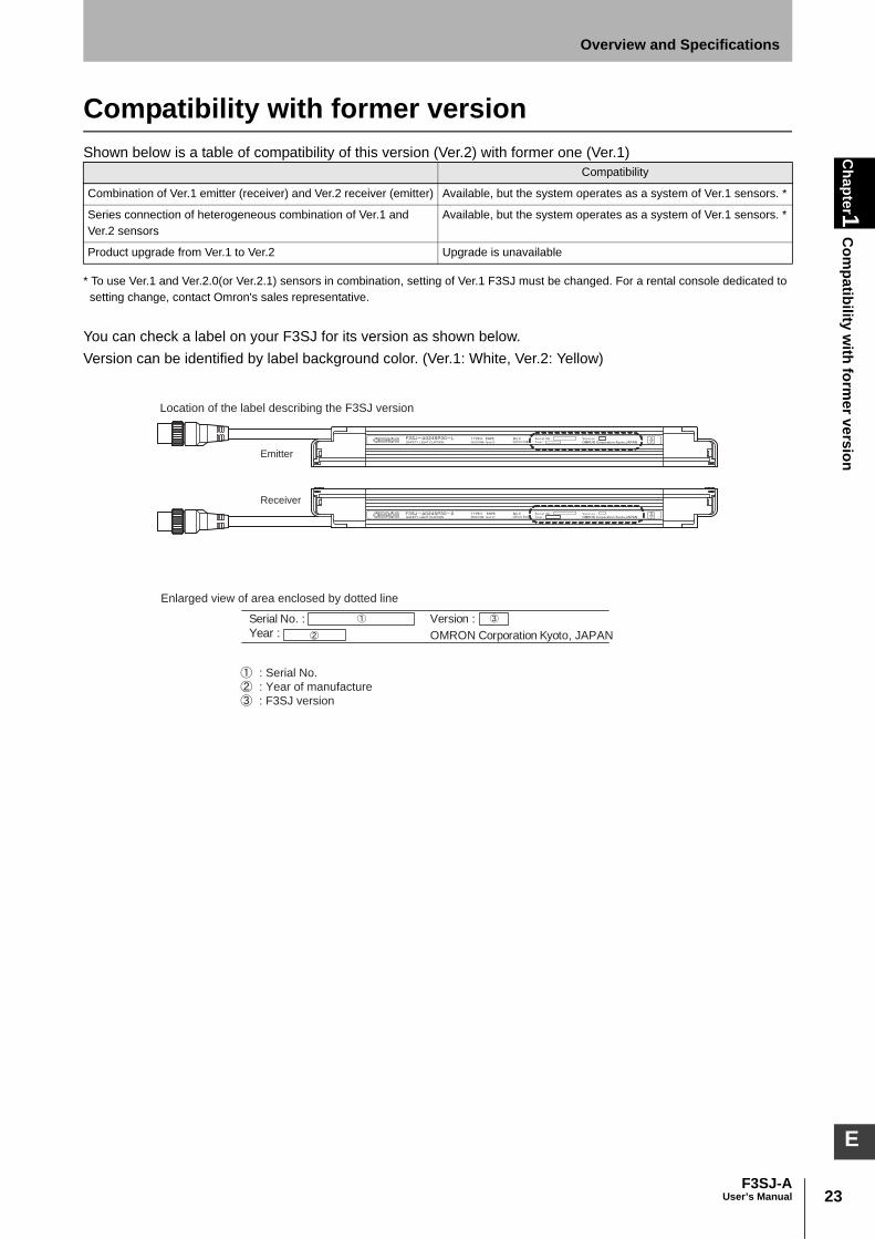
You can check a label on your F3SJ for its version as shown below.Version can be identified by label background color. (Ver.1: White, Ver.2: Yellow)
Compatibility
Combination of Ver.1 emitter (receiver) and Ver.2 receiver (emitter) Available, but the system operates as a system of Ver.1 sensors. *
Series connection of heterogeneous combination of Ver.1 and Ver.2 sensors
Available, but the system operates as a system of Ver.1 sensors. *
Product upgrade from Ver.1 to Ver.2 Upgrade is unavailable
Year :
Serial No. : Version :
OMRON Corporation Kyoto, JAPAN
Location of the label describing the F3SJ version
Emitter
Receiver
Enlarged view of area enclosed by dotted line
: Serial No.
: Year of manufacture
: F3SJ version
24
Chapter1
Com
patibility with form
er version
F3SJ-AUser’s Manual
Overview and Specifications

Chapter2
System C
onfiguration and Functions
25F3SJ-A
User’s Manual
E
Chapter2 System Configuration and Functions
How to Select a System 26
Selection Flow Chart 26Combination of Functions 26
Basic System 27
Wiring Diagrams 27Interlock Function 29External Test Function 31Self-Test Function 31Auxiliary Output (Non-Safety Output) 32Resetting Lockout 33External Device Monitoring Function 34
Muting System 35
Upgrading F3SJ for Muting System 36Standard Muting Mode 38Wiring Diagrams 40Installation Standard for Muting Sensors 42Installation Example 1 of Standard Muting Mode (using 2muting sensors) 42Installation Example 2 of Standard Muting Mode (using 4muting sensors) 46Override Function 52External Test Function 54Self-Test Function 54Auxiliary Output (Non-Safety Output) 55Resetting Lockout 55External Device Monitoring Function (EDM) 55

26
Chapter2
How
to Select a System
F3SJ-AUser’s Manual
System Configuration and Functions
How to Select a System
Selection Flow ChartRequired system configuration depends on functions to be used. Use the following flow chart todetermine the system.
Combination of FunctionsAvailability of functional combination is shown below. Other functions than these functions can becombined.O: Combination available
: Can be combined by using the PC tool for F3SJ to change the setting. (Cannot be combined byusing the setting console. For details, see Chapter 3. Setting Zone Adjacent Conditions, p.92.)
x: Combination unavailable
Fixed Blanking Function
Floating Blanking Function
Muting/Override Function
Warning Zone Function
Fixed Blanking Function - O
Floating Blanking Function -
Muting/Override Function O -
Warning Zone Function -
Using muting function
Basic system + Functional setting
change by the setting tool
Using fixed blanking
Using floating blanking
Changing operating range
Using/changing other function
Using fixed blanking
Using floating blanking
Changing operating range
Using/changing other function
Basic system
Muting system + Functional setting
change by the setting tool *1
Muting system *1
NO NO
NO
YES
YES
YES
*1 Key cap for muting (F39-CN6) is required.
27F3SJ-A
User’s Manual
Chapter2
Basic System
System Configuration and Functions
E
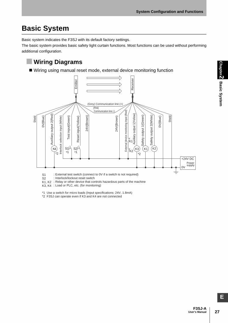
Basic SystemBasic system indicates the F3SJ with its default factory settings. The basic system provides basic safety light curtain functions. Most functions can be used without performingadditional configuration.
Wiring DiagramsWiring using manual reset mode, external device monitoring function
S1
S2
K1, K2
K3, K4
: External test switch (connect to 0V if a switch is not required)
: Interlock/lockout reset switch
: Relay or other device that controls hazardous parts of the machine
: Load or PLC, etc. (for monitoring)
*1 Use a switch for micro loads (Input specifications: 24V, 1.8mA)
*2 F3SJ can operate even if K3 and K4 are not connected
Inte
rlock s
ele
ction input (W
hite)
(Grey) Communication line (+)
(Pink)
Communication line (-)
0V
(Blu
e)
0V
(Blu
e)
Shi
eld
Shi
eld
Test in
put(
Gre
en)
Reset in
put(
Yello
w)
24V
(Bro
wn)
24V
(Bro
wn)
Ext
ern
al d
evi
ce m
onito
ring in
put (R
ed)
Auxi
liary
outp
ut 1(Y
ello
w)
Safe
ty o
utp
ut 1(G
reen)
Safe
ty o
utp
ut 2(W
hite)
Auxili
ary
outp
ut 2(R
ed)
S1 S2
*1 *1*2*2
Em
itte
r
Receiv
er
K4 K3K2
K1
K1 K2
0V
Powersupply
+24V DC

28
Chapter2
Basic System
F3SJ-AUser’s Manual
System Configuration and Functions
Wiring for Auto Reset ModeWiring the emitter’s circuit as shown below provides auto reset mode.
Wiring When External Device Monitoring Function Is Not Used1.Disabling external device monitoring function by the setting toolOr2.The external device monitoring function is disabled by connecting auxiliary output 1 and externaldevice monitoring input as shown below, when auxiliary output 1 settings have not been changed(output operation mode is "safety output information" and reverse output mode is "enabled").
For mode setting of auxiliary output p.95
S1
* 1
S3
* 1
+24V DC
0V
* 2
K4
Powersupply
Inte
rlo
ck s
ele
ctio
n in
pu
t (W
hite
)
Em
itte
r
(Grey) Communication line (+)
(Pink) Communication line (-)
0V
(Blu
e)
Shi
eld
Te
st
inp
ut(
Gre
en
)
Re
se
t in
pu
t(Y
ello
w)
24
V(B
row
n)
Au
xili
ary
ou
tpu
t 2
(Re
d)
S1
S3
K4
: External test switch (connect to 0V if a switch is not required)
: Lockout reset switch (connect to 24V if a switch is not required)
: Load or PLC, etc. (for monitoring)
*1 Use a switch for micro loads
(Input specifications: 24V, 1.8mA)
*2 F3SJ can operate even if K4 is not connected
*1
K1 K2K3
+24V DC
0V
Re
ce
ive
r
(Grey) Communication line (+)
(Pink) Communication line (-)
0V
(Blu
e)
Powersupply
Shi
eld
24
V(B
row
n)
Ext
ern
al d
evi
ce
mo
nito
rin
g in
pu
t(R
ed
)
Au
xilia
ry o
utp
ut
1(Y
ello
w)
Sa
fety
ou
tpu
t 1
(Gre
en
)
Sa
fety
ou
tpu
t 2
(Wh
ite
)
K1, K2
K3
: Relay or other device that controls
hazardous parts of the machine
: Load or PLC, etc. (for monitoring)
*1 F3SJ can operate even if K3 is not connected.
If K3 is not required, connect auxiliary output 1
to external device monitoring input only.

29F3SJ-A
User’s Manual
Chapter2
Basic System
System Configuration and Functions
E
Ref.: Minimum Wiring Required to Check the Operation of the F3SJ(Wiring for auto reset mode and deactivated external device monitoring function)
Interlock FunctionThe F3SJ turns the safety outputs OFF when its power is turned on or its beam is interrupted and holdsthis state until reset input is applied. This state is called "interlock".Two methods can be used to reset the interlock state: "auto reset that automatically turns controloutputs ON when the interrupting object is removed" and "manual reset mode that keeps controloutputs OFF until a reset signal is provided, if the interrupting object is removed".
Auto ResetWhen the interrupting object is removed from the detection zone, the safety outputs automatically turnON. Auto reset is used on machines where a worker is not able to enter the zone between thedetection zone and the hazardous part of the machine.
To wire auto reset:1. Open the interlock selection input line, or short-circuit it to 0 to 1.5V (pin 1/white). 2. Short-circuit the reset input line to 9 to 24V (pin 4/yellow). 3. Turn ON the power to the F3SJ.
Wiring for Auto Reset Mode p.28
Op
en
Op
en
Op
en
Op
en
Op
en
+24V DC
0V
Inte
rlo
ck s
ele
ctio
n in
pu
t (W
hite
)
Em
itte
r
Re
ce
ive
r
(Grey) Communication line (+)
(Pink)
Communication line (-)
0V
(Blu
e)
0V
(Blu
e)
Powersupply
Shi
eld
Shi
eld
Te
st
inp
ut(
Gre
en
)
Re
se
t in
pu
t(Y
ello
w)
24
V(B
row
n)
24
V(B
row
n)
Ext
ern
al d
evi
ce m
on
itorin
g in
pu
t (R
ed
)
Au
xilia
ry o
utp
ut
1(Y
ello
w)
Sa
fety
ou
tpu
t 1
(Gre
en
)
Sa
fety
ou
tpu
t 2
(Wh
ite
)
Au
xili
ary
ou
tpu
t 2
(Re
d)
S3
0V
S3 : Lockout reset switch
(Short-circuit to 24V when the switch is not required.)
+24V DC
Powersupply
Inte
rlo
ck s
ele
ctio
n in
pu
t (W
hite
)
Re
se
t in
pu
t(Y
ello
w)

30
Chapter2
Basic System
F3SJ-AUser’s Manual
System Configuration and Functions
Manual ResetWhen a reset input is given while no interrupting object exists in a detection zone, the safety outputsturn ON. This allows the machine to be manually reset using a reset switch after ensuring safety,preventing unexpected startup (EN1037).
A sensor enters interlock state when:•The power is turned ON (start interlock). This is useful if you want to keep the machine stopped until
start inspection is completed after the power is turned ON. •F3SJ is blocked (restart interlock). After the F3SJ is blocked and the machine stops, the machine can
be restarted after safety is ensured.
Manual reset wiring procedure: 1. Connect the interlock selection input line to 9 to 24V. (pin 1/ white) 2. Connect the reset input line to 9 to 24V via a reset switch (N.O. contact). (pin 4/ yellow)3. Keep the reset switch contact open, and turn ON the power to the F3SJ.
Wiring for manual reset mode p.27
To reset: 1. Cycle the reset switch to apply a voltage of 9 to 24V for 250ms or longer to the reset input, and then
open the switch to apply a 0 to 1.5V signal or open circuit. A reset switch must be installed outside of the hazardous zone in a location that provides a clear view of the hazardouszone.
Setting Change by the Setting ToolFunctional setting is available through the setting tool.•Disabling start or restart interlock
For details, see p.100
ON
OFF
ON
OFF
Safety output
/Blocked
Unblocked Unblocked
Blocked
Sensor status Normal operationInterlock state
Reset Input
250ms min.
S2
0V
S2 : Interlock/lockout reset switch
+24V DC
Powersupply
Inte
rlo
ck s
ele
ctio
n in
pu
t (W
hite
)
Re
se
t in
pu
t(Y
ello
w)

31F3SJ-A
User’s Manual
Chapter2
Basic System
System Configuration and Functions
E
External Test Function This function forcibly stops the emission using an external signal. It can be used to verify that a safetysystem should properly stop when F3SJ is interrupted.To stop the emission, apply 9 to 24V to the emitter's test input line. The voltage must be applied for aperiod 4 times that of Toff or longer.
Ton: Response time of safety output's OFF to ON, Toff: Response time of safety output's ON to OFFResponse time p.17
Operation of the F3SJ's Indicators When External Test Function is PerformedBlanking/test indicator blinks when voltage is applied to the test input.
Self-Test FunctionThe F3SJ performs the self-test when power is turned ON (within 2 second, or 2.2 seconds in case ofseries connection) to check for errors. Also, it regularly performs the self-test (within the responsetime) while operating.
If an error is found in the self-test, the F3SJ enters lockout state, keeps the safety outputs in the OFFstate, and indicates the error at the same time.
Self-Test DetailsThe self-test detects the types of errors described below.
Emitter•Failure of emitter element or circuit•CPU failure•Broken or short-circuited cable
Receiver•Abnormal external power supply voltage•Failure of internal power supply circuit•Failure of receiver element or detection circuit•CPU failure•Memory failure
Test input
Safety output
OFF
ON
ON
OFF
Toff x 4 or less Ton x 2 or less
Subsequently performs periodic test
Power supplyON
OFF
Self-testON
OFF
Within 2 s
(Within 2.2 s)
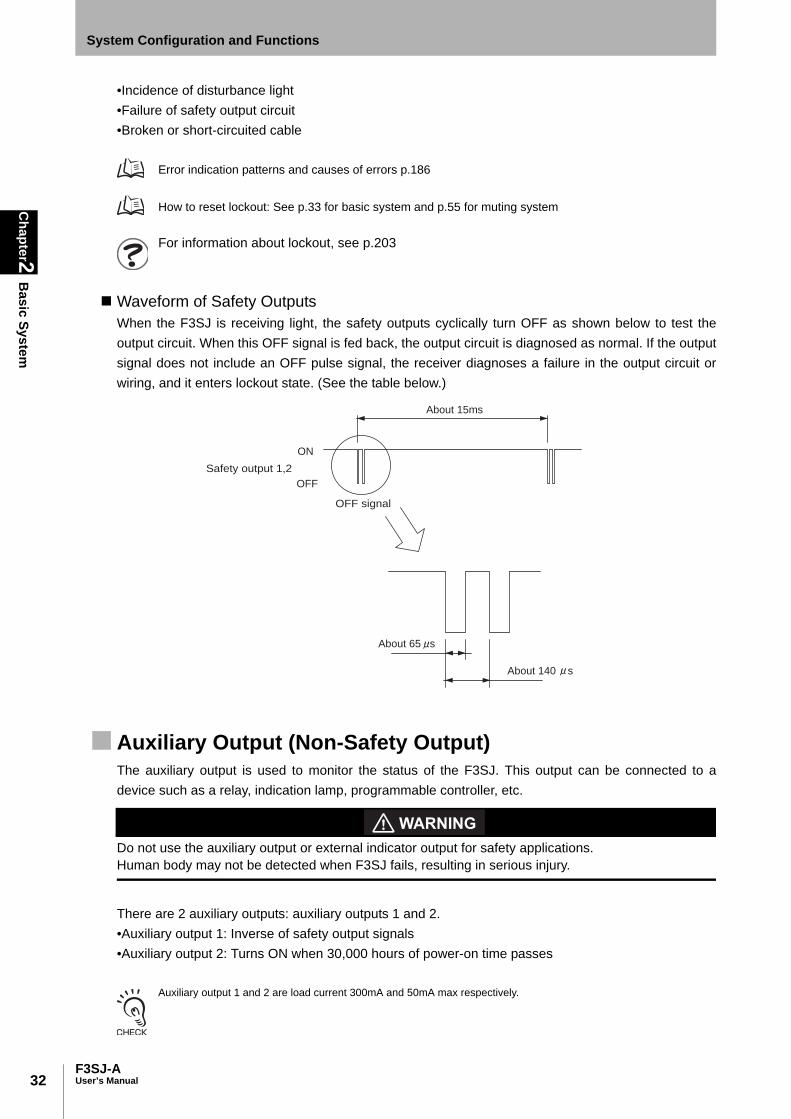
32
Chapter2
Basic System
F3SJ-AUser’s Manual
System Configuration and Functions
•Incidence of disturbance light•Failure of safety output circuit•Broken or short-circuited cable
Error indication patterns and causes of errors p.186
How to reset lockout: See p.33 for basic system and p.55 for muting system
For information about lockout, see p.203
Waveform of Safety OutputsWhen the F3SJ is receiving light, the safety outputs cyclically turn OFF as shown below to test theoutput circuit. When this OFF signal is fed back, the output circuit is diagnosed as normal. If the outputsignal does not include an OFF pulse signal, the receiver diagnoses a failure in the output circuit orwiring, and it enters lockout state. (See the table below.)
Auxiliary Output (Non-Safety Output)The auxiliary output is used to monitor the status of the F3SJ. This output can be connected to adevice such as a relay, indication lamp, programmable controller, etc.
Do not use the auxiliary output or external indicator output for safety applications. Human body may not be detected when F3SJ fails, resulting in serious injury.
There are 2 auxiliary outputs: auxiliary outputs 1 and 2.•Auxiliary output 1: Inverse of safety output signals •Auxiliary output 2: Turns ON when 30,000 hours of power-on time passes
Auxiliary output 1 and 2 are load current 300mA and 50mA max respectively.
Safety output 1,2
OFF signal
ON
OFF
About 65 s
About 140 s
About 15ms
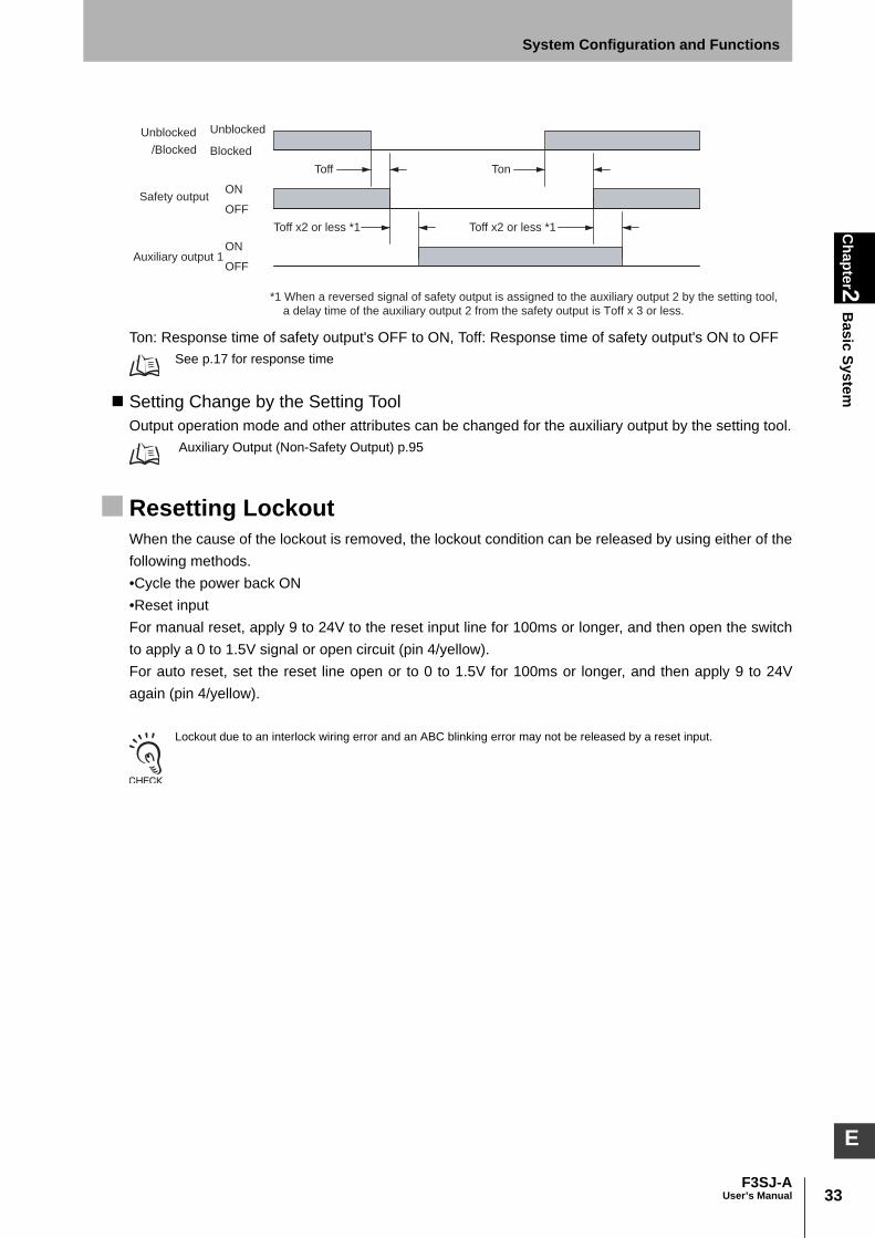
33F3SJ-A
User’s Manual
Chapter2
Basic System
System Configuration and Functions
E
Ton: Response time of safety output's OFF to ON, Toff: Response time of safety output's ON to OFFSee p.17 for response time
Setting Change by the Setting ToolOutput operation mode and other attributes can be changed for the auxiliary output by the setting tool.
Auxiliary Output (Non-Safety Output) p.95
Resetting LockoutWhen the cause of the lockout is removed, the lockout condition can be released by using either of thefollowing methods.•Cycle the power back ON•Reset inputFor manual reset, apply 9 to 24V to the reset input line for 100ms or longer, and then open the switchto apply a 0 to 1.5V signal or open circuit (pin 4/yellow). For auto reset, set the reset line open or to 0 to 1.5V for 100ms or longer, and then apply 9 to 24Vagain (pin 4/yellow).
Lockout due to an interlock wiring error and an ABC blinking error may not be released by a reset input.
ON
OFF
ON
OFF
Toff
/Blocked
Unblocked
Blocked
Unblocked
Auxiliary output 1
Safety output
Toff x2 or less *1
Ton
Toff x2 or less *1
*1 When a reversed signal of safety output is assigned to the auxiliary output 2 by the setting tool,
a delay time of the auxiliary output 2 from the safety output is Toff x 3 or less.

34
Chapter2
Basic System
F3SJ-AUser’s Manual
System Configuration and Functions
External Device Monitoring FunctionThis function detects malfunctions, such as welding, in external relays (or contactors) that control thehazardous zone of a machine. This function constantly monitors that a specified voltage is applied to the receiver's external devicemonitoring input line, and enters lockout state when an error occurs. The relay's operational delay canbe up to 0.3s(can be changed by the setting tool) without being evaluated as an error. For example, if the (N.C.) contact is not closed and a specified voltage is not applied to the externaldevice monitoring line within 0.3s after the safety outputs turn from ON to OFF, it is evaluated as anerror and enters a lockout state.To utilize this function properly, use safety relays and contactors that have forcibly guided ormechanically linked contact structure.
Wiring Perform wiring so that 9 to 24V is applied to the external device monitoring line via the external relay'snormally closed (N.C.) contact. When external device monitoring function is not being used, apply auxiliary output 1 (output operationmode is safety output information and reverse output mode is being enabled) for which setting is notchanged to the external device monitoring input or disable external device monitoring function by thesetting tool.
- Wiring when external device monitoring function is used p.27- Wiring when external device monitoring function is not used p.28
Timing ChartThe F3SJ reads out a device monitoring input value 0.5s or later after the power of the F3SJ is turnedON. If the status of the safety outputs is changed back to the original status within the allowable delaytime, the F3SJ will not enter the lockout state.
T1: Allowable delay time (can be changed by the setting tool. 0.1 to 2.5s)
Setting Change by the Setting ToolFollowing functions can be configured by the setting tool.
External Device Monitoring Function p.102
•Disabling external device monitoring function•Changing allowable delay time (0.1 to 2.5s)
Operation of the F3SJ's Internal Indicators When External Device MonitoringFunction is PerformedWhen an input is applied to the external device monitoring input, the external device monitoringindicator turns ON.
ON
OFF
T1=0.3s T1=0.3s
ON
OFF
Unblocked
/Blocked
Unblocked
Blocked
External device
monitoring input
Safety outputLockout
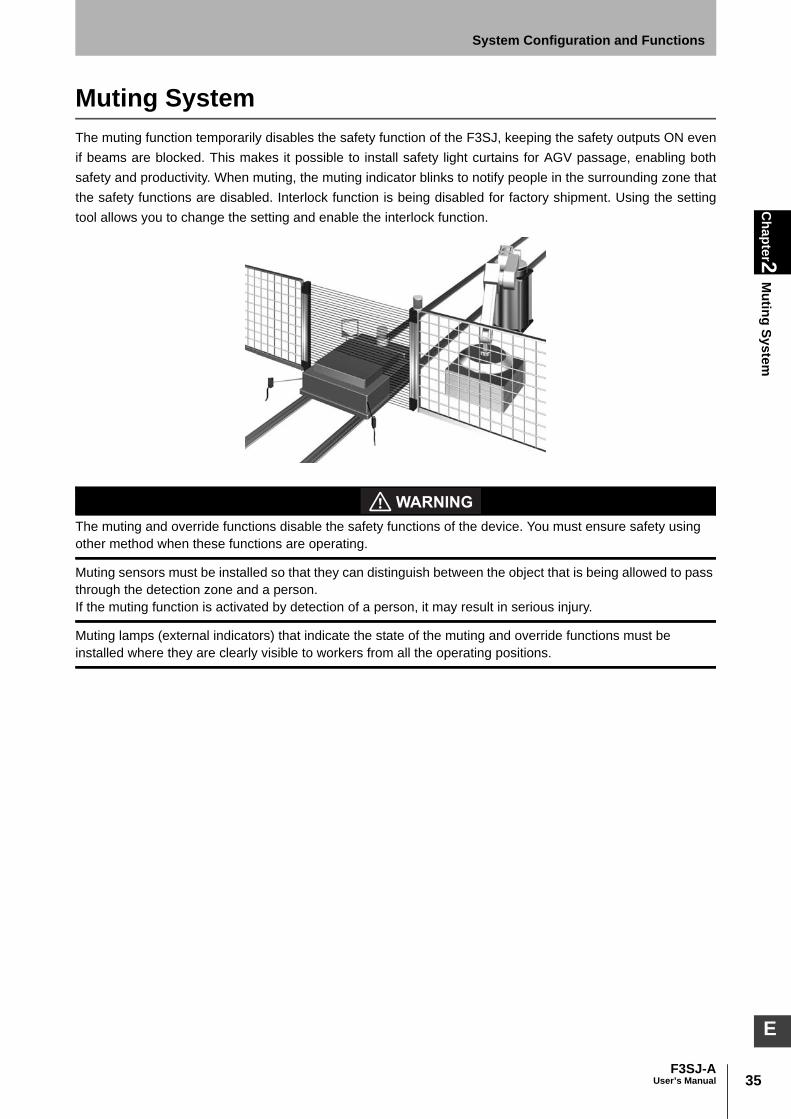
35F3SJ-A
User’s Manual
Chapter2
Muting System
System Configuration and Functions
E
Muting SystemThe muting function temporarily disables the safety function of the F3SJ, keeping the safety outputs ON evenif beams are blocked. This makes it possible to install safety light curtains for AGV passage, enabling bothsafety and productivity. When muting, the muting indicator blinks to notify people in the surrounding zone thatthe safety functions are disabled. Interlock function is being disabled for factory shipment. Using the settingtool allows you to change the setting and enable the interlock function.
The muting and override functions disable the safety functions of the device. You must ensure safety using other method when these functions are operating.
Muting sensors must be installed so that they can distinguish between the object that is being allowed to pass through the detection zone and a person. If the muting function is activated by detection of a person, it may result in serious injury.
Muting lamps (external indicators) that indicate the state of the muting and override functions must be installed where they are clearly visible to workers from all the operating positions.

36
Chapter2
Muting System
F3SJ-AUser’s Manual
System Configuration and Functions
Upgrading F3SJ for Muting System1. Remove the caps of the emitter and receiver.(driver comes with key cap for muting)2. Install a muting lamp (external indicator) on either the emitter or the receiver. 3. Attach the key cap for muting to the emitter/receiver on which the muting lamp (external indicator) was
not installed.
Muting SensorThe muting sensor is the sensor that is the trigger for temporarily disabling the F3SJ's safety functions.Through-beam or retro-reflective photoelectric sensors, proximity sensors, or limit switches can beused as muting sensors. (recommendation: OMRON E3Z series, E2E series (3-wire type), D4N series)Use 3-wire type PNP output or N.O. type contact. Two-wire type sensor cannot be used.
Muting Lamp (External Indicator)You may need a muting lamp depending on your application or as a result of a risk assessment. Beforedetermining the use of the muting lamp, check laws and regulations of the country or region where theF3SJ-A is used and make sure of full compliance with them. For the muting lamp, use F39-A01P-PAC, or a F39-JJ3N universal indicator cable and a commercially available external indicator. Enablingexternal indicator output diagnosis function allows breakage and short circuit detection of externalindicator or muting lamp connected to the output.
Recommended External Indicators p.126External Indicator Output Diagnosis Function p.99
Key cap for muting
Model F39-CN6 (Case color : Orange)
External indicator set
Model F39-A01P -PAC
Model F39-JJ3N
1.1.1.1.
2.2.
3.3.
Commercially
available
indicator
Universal indicator
cable
Muting lamp (external indicator)
Cap
(Case color : Black)
Cap
(Case color : Black)
Brown: +, Blue: -
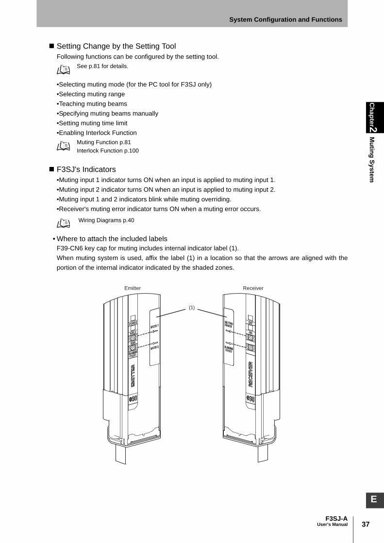
37F3SJ-A
User’s Manual
Chapter2
Muting System
System Configuration and Functions
E
Setting Change by the Setting ToolFollowing functions can be configured by the setting tool.
See p.81 for details.
•Selecting muting mode (for the PC tool for F3SJ only)•Selecting muting range•Teaching muting beams•Specifying muting beams manually•Setting muting time limit•Enabling Interlock Function
Muting Function p.81 Interlock Function p.100
F3SJ's Indicators •Muting input 1 indicator turns ON when an input is applied to muting input 1.•Muting input 2 indicator turns ON when an input is applied to muting input 2.•Muting input 1 and 2 indicators blink while muting overriding.•Receiver's muting error indicator turns ON when a muting error occurs.
Wiring Diagrams p.40
• Where to attach the included labelsF39-CN6 key cap for muting includes internal indicator label (1). When muting system is used, affix the label (1) in a location so that the arrows are aligned with theportion of the internal indicator indicated by the shaded zones.
Emitter Receiver
(1)
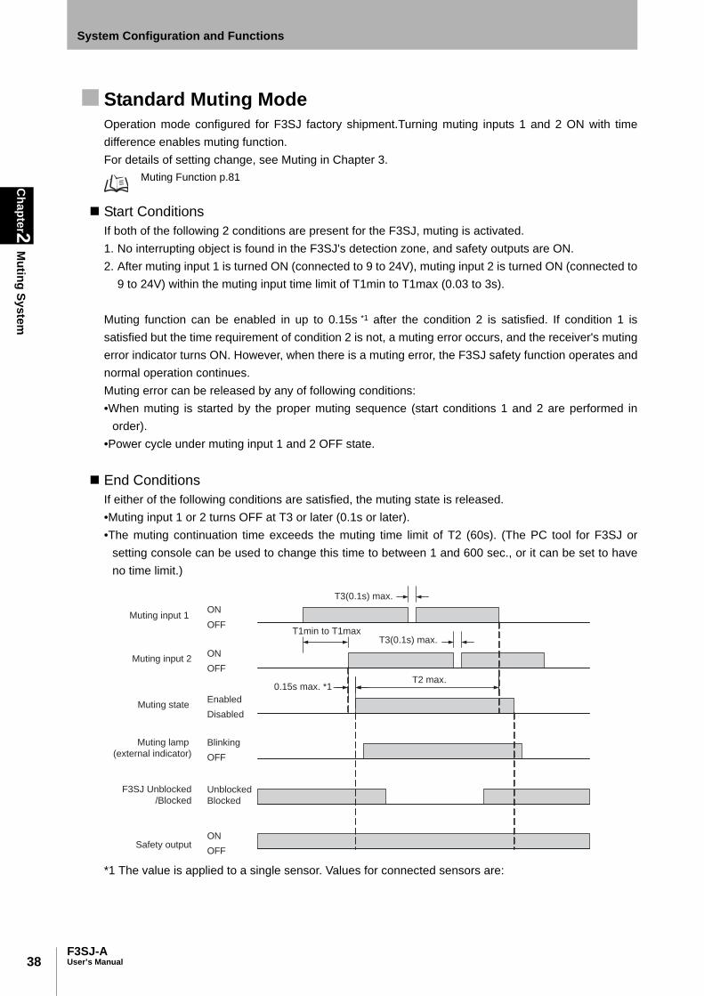
38
Chapter2
Muting System
F3SJ-AUser’s Manual
System Configuration and Functions
Standard Muting ModeOperation mode configured for F3SJ factory shipment.Turning muting inputs 1 and 2 ON with timedifference enables muting function.For details of setting change, see Muting in Chapter 3.
Muting Function p.81
Start ConditionsIf both of the following 2 conditions are present for the F3SJ, muting is activated. 1. No interrupting object is found in the F3SJ's detection zone, and safety outputs are ON. 2. After muting input 1 is turned ON (connected to 9 to 24V), muting input 2 is turned ON (connected to
9 to 24V) within the muting input time limit of T1min to T1max (0.03 to 3s).
Muting function can be enabled in up to 0.15s *1 after the condition 2 is satisfied. If condition 1 issatisfied but the time requirement of condition 2 is not, a muting error occurs, and the receiver's mutingerror indicator turns ON. However, when there is a muting error, the F3SJ safety function operates andnormal operation continues.Muting error can be released by any of following conditions:•When muting is started by the proper muting sequence (start conditions 1 and 2 are performed in
order).•Power cycle under muting input 1 and 2 OFF state.
End ConditionsIf either of the following conditions are satisfied, the muting state is released. •Muting input 1 or 2 turns OFF at T3 or later (0.1s or later). •The muting continuation time exceeds the muting time limit of T2 (60s). (The PC tool for F3SJ or
setting console can be used to change this time to between 1 and 600 sec., or it can be set to haveno time limit.)
*1 The value is applied to a single sensor. Values for connected sensors are:
ON
OFF
ON
OFF
Blinking
OFF
T3(0.1s) max.
T3(0.1s) max.
Muting lamp
(external indicator)
Muting input 1
Safety output
Muting input 2
Enabled
Disabled
F3SJ Unblocked
/BlockedUnblocked
Blocked
ON
OFF
Muting state
T1min to T1max
T2 max.0.15s max. *1
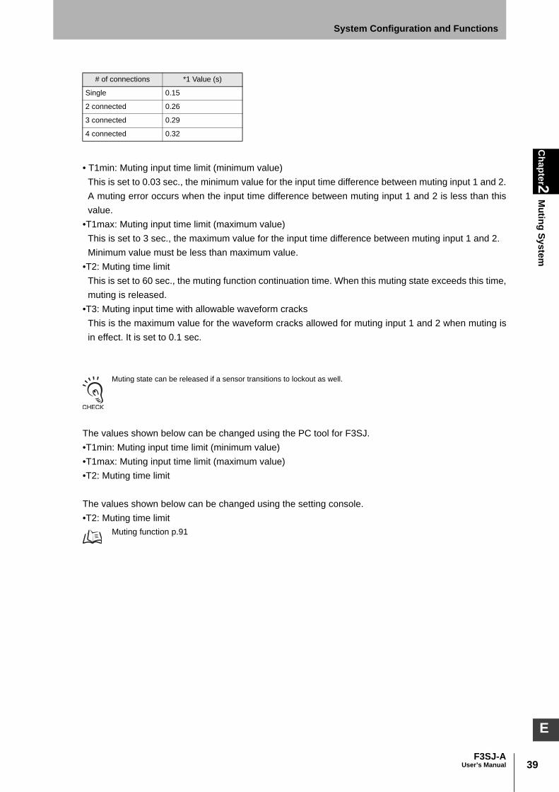
39F3SJ-A
User’s Manual
Chapter2
Muting System
System Configuration and Functions
E
• T1min: Muting input time limit (minimum value)This is set to 0.03 sec., the minimum value for the input time difference between muting input 1 and 2.A muting error occurs when the input time difference between muting input 1 and 2 is less than thisvalue.
•T1max: Muting input time limit (maximum value)This is set to 3 sec., the maximum value for the input time difference between muting input 1 and 2.Minimum value must be less than maximum value.
•T2: Muting time limitThis is set to 60 sec., the muting function continuation time. When this muting state exceeds this time,muting is released.
•T3: Muting input time with allowable waveform cracksThis is the maximum value for the waveform cracks allowed for muting input 1 and 2 when muting isin effect. It is set to 0.1 sec.
Muting state can be released if a sensor transitions to lockout as well.
The values shown below can be changed using the PC tool for F3SJ.•T1min: Muting input time limit (minimum value)•T1max: Muting input time limit (maximum value)•T2: Muting time limit
The values shown below can be changed using the setting console.•T2: Muting time limit
Muting function p.91
# of connections *1 Value (s)
Single 0.15
2 connected 0.26
3 connected 0.29
4 connected 0.32
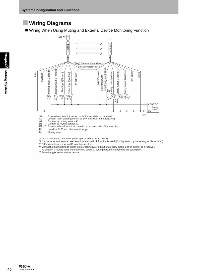
40
Chapter2
Muting System
F3SJ-AUser’s Manual
System Configuration and Functions
Wiring DiagramsWiring When Using Muting and External Device Monitoring Function
S1 : External test switch (connect to 0V if a switch is not required)S2 : Lockout reset switch (connect to 24V if a switch is not required)A1 : Contact by muting sensor A1B1 : Contact by muting sensor B1K1,K2 : Relay or other device that controls hazardous parts of the machine
M1 : Muting lamp
Mu
tin
g in
pu
t 1
(W
hite
)
Muting input 2 (
Red)
K3 : Load or PLC, etc. (for monitoring)
*1 Use a switch for small loads (input specifications: 24V, 1.8mA)
*2 Can work as an interlock reset switch when interlock function is used. (Configuration by the setting tool is required)
*3 F3SJ operates even when K3 is not connected.
*4 Connect a muting lamp to either of external indicator output or auxiliary output 1 of an emitter or a receiver.
To connect a muting lamp to the auxiliary output 1, setting must be changed by the setting tool.
M1 *4
K1
K2S1
*1 *1 * 2S2A1B1
* 3 * 4
K1 K2K3
+24V DC
0V
Em
itte
r
Re
ce
ive
r
(Grey) Communication line (+)
(Pink) Communication line (-)
0V
(Blu
e)
0V
(Blu
e)
Powersupply
Shi
eld
Shi
eld
Te
st
inp
ut(
Gre
en
)
Re
se
t in
pu
t(Y
ello
w)
24
V(B
row
n)
24
V(B
row
n)
Ext
ern
al d
evi
ce
monito
ring in
put (R
ed)
Au
xilia
ry o
utp
ut
1(Y
ello
w)
Sa
fety
ou
tpu
t 1
(Gre
en
)
Sa
fety
ou
tpu
t 2
(Wh
ite
)
*4
55 **
5* Two-wire type sensor cannot be used.
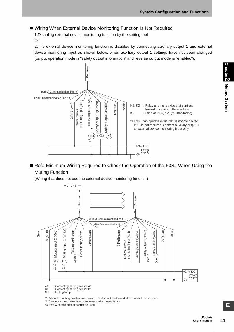
41F3SJ-A
User’s Manual
Chapter2
Muting System
System Configuration and Functions
E
Wiring When External Device Monitoring Function Is Not Required1.Disabling external device monitoring function by the setting toolOr2.The external device monitoring function is disabled by connecting auxiliary output 1 and externaldevice monitoring input as shown below, when auxiliary output 1 settings have not been changed(output operation mode is "safety output information" and reverse output mode is "enabled").
Ref.: Minimum Wiring Required to Check the Operation of the F3SJ When Using theMuting Function (Wiring that does not use the external device monitoring function)
*1
K3
+24V DC
0V
K1 K2
Re
ce
ive
r
(Grey) Communication line (+)
(Pink) Communication line (-)
0V
(Blu
e)
Powersupply
Shi
eld
24
V(B
row
n)
Ext
ern
al d
evi
ce
mo
nito
rin
g in
pu
t (R
ed
)
Auxi
liary
outp
ut 1(Y
ello
w)
Sa
fety
ou
tpu
t 1
(Gre
en
)
Sa
fety
ou
tpu
t 2
(Wh
ite
)K1, K2
K3
: Relay or other device that controls
hazardous parts of the machine
: Load or PLC, etc. (for monitoring)
*1 F3SJ can operate even if K3 is not connected.
If K3 is not required, connect auxiliary output 1
to external device monitoring input only.
Open
Open
Open
A1B1
* 1*1
M1 *1 *2
+24V DC
0V
A1 : Contact by muting sensor A1B1 : Contact by muting sensor B1M1 : Muting lamp
Mu
tin
g in
pu
t 1
(W
hite
)
Muting input 2 (
Red)
*1 When the muting function's operation check is not performed, it can work if this is open.
*2 Connect either the emitter or receiver to the muting lamp.
Em
itte
r
Re
ce
ive
r
(Grey) Communication line (+)
(Pink) Communication line (-)
0V
(Blu
e)
0V
(Blu
e)
Powersupply
Shi
eld
Shi
eld
Te
st
inp
ut(
Gre
en
)
Re
se
t in
pu
t(Y
ello
w)
24
V(B
row
n)
24
V(B
row
n)
Ext
ern
al d
evi
ce
monito
ring in
put (R
ed)
Au
xilia
ry o
utp
ut
1(Y
ello
w)
Sa
fety
ou
tpu
t 1
(Gre
en
)
Sa
fety
ou
tpu
t 2
(Wh
ite
)
33 **
3* Two-wire type sensor cannot be used.

42
Chapter2
Muting System
F3SJ-AUser’s Manual
System Configuration and Functions
Installation Standard for Muting Sensors•Set the muting sensors so that they can detect all of the passing detection objects (palettes,
automobiles, etc.). Do not install in a position so that only the front or rear end of the detection objectis detected.
•Set the muting sensors so that they detect the objects even when they are loaded on palettes or othertransport devices.
•Also, install the F3SJ and muting sensors so that each object passes through all muting sensorsbefore the next object arrives at the first muting sensor. Also, install all F3SJ and muting sensors sothat no person is able to accidentally enter the hazardous zone while the muting function is enabled.
•If objects' speeds can vary, muting time limit must be taken into consideration.
Installation Example 1 of Standard Muting Mode (using 2muting sensors)This is an example of 2 retro-reflective type photoelectric sensors used as muting sensors installed in across pattern. Use 2 sensors when the length L of the workpieces are not constant or are insufficient.
1. Before a workpiece passes through
The output state of muting sensors A1 and B1 are both OFF (contacts A1 and B1 are open due tomuting output), and the safety function of the F3SJ is working. In this example where 2 muting sensors are used, the crossover point of muting sensors A1 and B1must be located in the hazardous zone. This configuration prevents the muting function from beingenabled by a person passing through the crossover point.
L
F3SJ
F3SJ
d1=D1
B1
A1
VWorkpiece
Hazardous zone
Reflector
Reflector
The crossover point of muting sensors
A1 and B1 must be located within the
hazardous zone
L: Length of workpiece
d1: Maximum distance required for the muting sensor to keep the muting function enabled
D1: Minimum distance required for the muting sensor to keep the muting function enabled
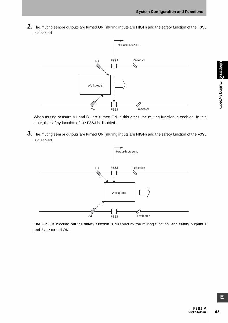
43F3SJ-A
User’s Manual
Chapter2
Muting System
System Configuration and Functions
E
2. The muting sensor outputs are turned ON (muting inputs are HIGH) and the safety function of the F3SJis disabled.
When muting sensors A1 and B1 are turned ON in this order, the muting function is enabled. In thisstate, the safety function of the F3SJ is disabled.
3. The muting sensor outputs are turned ON (muting inputs are HIGH) and the safety function of the F3SJis disabled.
The F3SJ is blocked but the safety function is disabled by the muting function, and safety outputs 1and 2 are turned ON.
F3SJ
F3SJ
B1
A1
Workpiece
Hazardous zone
Reflector
Reflector
F3SJ
F3SJ
B1
A1
Workpiece
Reflector
Reflector
Hazardous zone

44
Chapter2
Muting System
F3SJ-AUser’s Manual
System Configuration and Functions
4. The muting function is released
Muting sensor A1 is turned OFF, the muting function is released, and the safety function of the F3SJ isenabled.
Installation DistanceThe minimum distance, D1 [ m ], required for muting sensors to keep the muting function enabled is
D1 < L . . . . . Formula (1)L [ m ] : Length of a workpiece
The maximum distance, d1 [ m ], required for muting sensors to keep the muting function enabled is V x T1min < d1 < V x T1max . . . . . Formula (2)
V [ m/s ] : Approach speed of a workpiece T1min [ s ] : Muting input time limit value (minimum). 0.03s.T1max [ s ] : Muting input time limit value (maximum). 3s.
Use the PC tool for F3SJ to change following values:•T1min: Muting input time limit value (minimum)•T1max: Muting input time limit value (maximum)
Muting function p.91
To enable the muting function, D1 and d1 must satisfy formulas (1) and (2), respectively. This distance must prevent the muting function from being enabled by a person passing through themuting sensors. Also, install the F3SJ and muting sensors so that a workpiece passes through all muting sensorsbefore the next workpiece arrives at the muting sensors.
F3SJ
F3SJ
B1
A1
Workpiece
Reflector
Reflector
Hazardous zone

45F3SJ-A
User’s Manual
Chapter2
Muting System
System Configuration and Functions
E
Wiring Diagrams
Timing Chart
*1 The value is applied to a single sensor. Values for connected sensors are:
•T1min: Muting input time limit (minimum value)This is set to 0.03 sec., the minimum value for the input time difference between muting input 1 and 2.A muting error occurs when the input time difference between muting input 1 and 2 is less than thisvalue.
•T1max: Muting input time limit (maximum value)This is set to 3 sec., the maximum value for the input time difference between muting input 1 and 2.
•T2: Muting time limitThis is set to 60 sec., the muting function continuation time. When this muting state exceeds this time,muting is released.
# of connections *1 Value (s)
Single 0.15
2 connected 0.26
3 connected 0.29
4 connected 0.32
B1A1
+24V DC
0V
A1
B1
F3SJ
Mu
tin
g I
np
ut
1(W
hite
)
Mu
tin
g I
np
ut
1(W
hite
)
Mu
tin
g I
np
ut
2(R
ed
)
Mu
tin
g I
np
ut
2(R
ed
)
Reflector
Reflector
Powersupply
Using a photoelectric switch as a muting sensor Using an N.O contact type switch as a muting sensor
A1, B1: Regressive reflection
photoelectric switch
- PNP Output
- ON when Interrupted
A1, B1: N.O contact type switch
Two-wire type muting sensor cannot be used.*
Muting sensor A1ON
OFF
Muting sensor B1ON
OFF
Safety output ON
OFF
Blinking
OFF
Enabled
Disabled
Muting lamp
(external indicator)
F3SJ Unblocked
/BlockedUnblocked
Blocked
T3(0.1s) max.
T3(0.1s) max.
0.15s max. *1T2 max.
Muting state
T1min to T1max
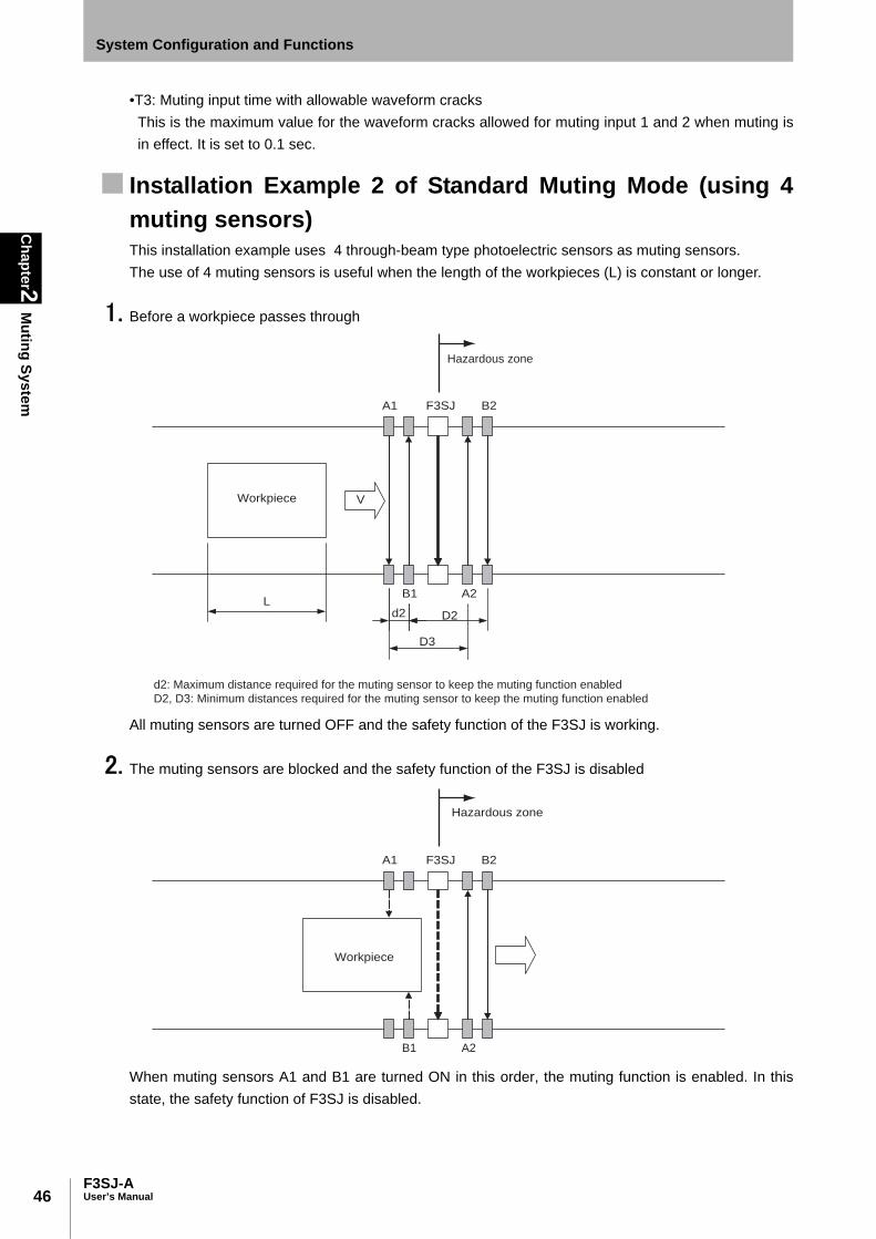
46
Chapter2
Muting System
F3SJ-AUser’s Manual
System Configuration and Functions
•T3: Muting input time with allowable waveform cracksThis is the maximum value for the waveform cracks allowed for muting input 1 and 2 when muting isin effect. It is set to 0.1 sec.
Installation Example 2 of Standard Muting Mode (using 4muting sensors)This installation example uses 4 through-beam type photoelectric sensors as muting sensors. The use of 4 muting sensors is useful when the length of the workpieces (L) is constant or longer.
1. Before a workpiece passes through
All muting sensors are turned OFF and the safety function of the F3SJ is working.
2. The muting sensors are blocked and the safety function of the F3SJ is disabled
When muting sensors A1 and B1 are turned ON in this order, the muting function is enabled. In thisstate, the safety function of F3SJ is disabled.
A1
B1
F3SJ
A2
B2
V
D3
Ld2 D2
Workpiece
Hazardous zone
d2: Maximum distance required for the muting sensor to keep the muting function enabled
D2, D3: Minimum distances required for the muting sensor to keep the muting function enabled
A1 F3SJ B2
B1 A2
Workpiece
Hazardous zone

47F3SJ-A
User’s Manual
Chapter2
Muting System
System Configuration and Functions
E
3. The muting sensors are blocked and the safety function of the F3SJ is disabled
Muting sensors A1 and B1 are turned OFF but A2 and B2 are ON, so the muting function is stillworking. Safety outputs 1 and 2 are turned ON.
4. The muting function is released
Muting sensor A2 is turned OFF and the muting function is released, and the safety function of theF3SJ is working.
Installation DistanceThe minimum distances, D2 [ m ] and D3 [ m ], required for the muting sensors to keep the mutingfunction enabled are
D2 < L . . . . . Formula (3)D3 < L . . . . . Formula (4)
L [ m ] : Length of a workpiece
The maximum distance, d2 [ m ], required for muting sensors to keep the muting function enabled is V x T1min < d2 < V x T1max . . . . . Formula (5)
V [ m/s ] : Approach speed of a workpiece T1min [ s ] : Muting input time limit value (minimum). 0.03s.T1max [ s ] : Muting input time limit value (maximum). 3s.
A1 F3SJ B2
B1 A2
Workpiece
Hazardous zone
A1
B1
F3SJ
A2
B2
Workpiece
Hazardous zone

48
Chapter2
Muting System
F3SJ-AUser’s Manual
System Configuration and Functions
Use the PC tool for F3SJ to change following values:T1min: Muting input time limit value (minimum)T1max: Muting input time limit value (maximum)
Muting function p.91
To enable the muting function, D2, D3, and d2 must satisfy formulas (3), (4), and (5), respectively. This distance must prevent the muting function from being enabled by a person passing through themuting sensors. Also, install the F3SJ and muting sensors so that a workpiece passes through allmuting sensors before the next workpiece arrives at the first muting sensor.
Wiring Diagrams
Workpiece Workpiece Workpiece Workpiece
Moving direction Moving direction
+24V DC
0V
A2A1 B2B1A2
A1 B2
B1
F3SJ
Mu
tin
g I
np
ut
1(W
hite
)
Mu
tin
g I
np
ut
1(W
hite
)
Mu
tin
g I
np
ut
2(R
ed
)
Mu
tin
g I
np
ut
2(R
ed
)
Powersupply
A1, B1, A2, B2 :
Regressive reflection
photoelectric switch
- PNP Output
- ON when Interrupted
A1, A2, B1, B2:
N.O contact type switch
Two-wire type muting sensor cannot be used.*

49F3SJ-A
User’s Manual
Chapter2
Muting System
System Configuration and Functions
E
Timing Chart
*1 The value is applied to a single sensor. Values for connected sensors are:
•T1min: Muting input time limit (minimum value)This is set to 0.03 sec., the minimum value for the input time difference between muting input 1 and 2.A muting error occurs when the input time difference between muting input 1 and 2 is less than thisvalue.
•T1max: Muting input time limit (maximum value)This is set to 3 sec., the maximum value for the input time difference between muting input 1 and 2.
•T2: Muting time limitThis is set to 60 sec., the muting function continuation time. When this muting state exceeds this time,muting is released.
•T3: Muting input time with allowable waveform cracksThis is the maximum value for the waveform cracks allowed for muting input 1 and 2 when muting isin effect. It is set to 0.1 sec.
# of connections *1 Value (s)
Single 0.15
2 connected 0.26
3 connected 0.29
4 connected 0.32
OFF
Safety outputON
OFF
Blinking
OFF
Blocked
Unblocked
ON
OFF
ON
ON
OFF
ON
OFF
Enabled
Disabled
T3(0.1s ) max.
T3(0.1s ) max.
T3(0.1s ) max.
T3(0.1s ) max.
T2 max.0.15s max. *1
Muting lamp
(External indicator)
F3SJ Unblocked
/Blocked
Muting sensor A1
Muting sensor B1
Muting sensor A2
Muting sensor B2
Muting state
T1min to T1max

50
Chapter2
Muting System
F3SJ-AUser’s Manual
System Configuration and Functions
Reference: Bidirectional MutingShown below is an example of bidirectional muting with 4 retro-reflective photoelectric sensors.It can be used for applications of workpiece approaching from both directions.Connect outer muting sensors A1 and A2 to the muting input 1 and inner muting sensors B1 and B2 tothe muting input 2.
1. Workpiece approaching from the left
2. Muting from an opposite direction is available as well
This arrangement example uses regressive reflection type E3Z-R series as a muting sensor.Arrangement must take mutual interference into account.Muting sensors must be installed so that a distance D3 between muting sensors A1 and A2 should besmaller than workpiece length L.As a muting sensor, a transmission or regressive reflection type photoelectric switch, proximity switch(3-wire type), or limit switch can be used. Two-wire type muting sensor cannot be used.
Distances d2 & D2 between muting sensors: p.47
V
F3SJ
A1 B1 B2 A2
Connect to muting Input 1
Connect to muting Input 2
Turning muting sensors ON in an order from
A1 to B1 sets F3SJ to a muting status.Workpiece
A1, A2, B1, B2: Retro-reflective photoelectric sensor
V
D3 L
A1 B1 B2 A2
F3SJd2 d2
WorkpieceTurning muting sensors ON in an order from
A2 to B2 sets F3SJ to a muting status.

51F3SJ-A
User’s Manual
Chapter2
Muting System
System Configuration and Functions
E
Reference: Preventing light interference of muting sensorWhen a photoelectric sensor is used as a muting sensor, light interference may cause a muting error of F3SJ.Light interference may occur due to:
(1) Interference between muting sensors• Use sensors with mutual interference prevention (such as retro-reflective E3Z-R series)• Use laser-type sensors (such as laser-type E3Z-LR series)• Take distance from a sensor causing the interference• Displace beams for each other to prevent interference (change installation height or place them crosswise)• Install a barrier• Attach interference prevention filter (provided for E3Z series as accessories)• Attach a slit to reduce light intensity (provided for E3Z series as accessories)• Lower the sensitivity• Reduce a distance between a workpiece and a muting sensor to prevent reflected light from a workpiece
(2) Interference to a muting sensor from F3SJ• Configure an operating range of F3SJ by the setting tool• Take distance (D) from a sensor causing the interference• Displace beams for each other to prevent interference (change installation height or place them crosswise)• Install a barrier• Arrange sensors in alternation• Lower the sensitivity
(3) Interference from a muting sensor to F3SJ• Use a red LED type sensor (such as retro-reflective E3Z-R series)• Use laser-type sensors (such as laser-type E3Z-LR series)• Take distance (D) from a sensor causing the interference• Displace beams for each other to prevent interference (change installation height or place them crosswise)• Install a barrier• Arrange sensors in alternation• Attach a slit to reduce light intensity (provided for E3Z series as accessories)
Mutual interference between a muting sensor and F3SJ in (2) and (3) above can be prevented byconfiguring D satisfying a formula shown below:
• If L = 0.2 to 3m D = 0.26m or larger• If L = 3m or larger D = L x tan5° = L x 0.088m or larger
L : Distance between an emitter and a receiver of F3SJD : Distance between a muting sensor and F3SJ
F3SJ B2A2A1 B1 A1 B1 A2 B2 A1 B1 A2 B2F3SJ F3SJ
D
WorkpieceWorkpieceWorkpiece
Reflected light Direct light Light from other F3SJ
L
(1)(1) (1)(1) (3) (2)
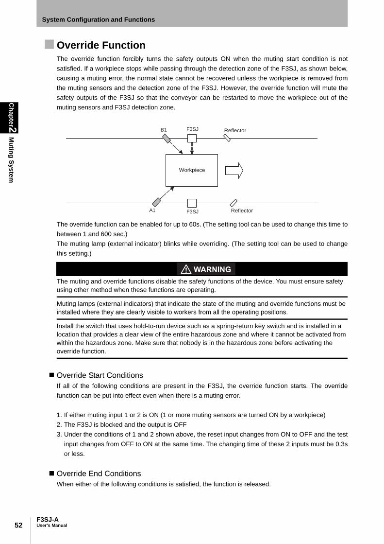
52
Chapter2
Muting System
F3SJ-AUser’s Manual
System Configuration and Functions
Override FunctionThe override function forcibly turns the safety outputs ON when the muting start condition is notsatisfied. If a workpiece stops while passing through the detection zone of the F3SJ, as shown below,causing a muting error, the normal state cannot be recovered unless the workpiece is removed fromthe muting sensors and the detection zone of the F3SJ. However, the override function will mute thesafety outputs of the F3SJ so that the conveyor can be restarted to move the workpiece out of themuting sensors and F3SJ detection zone.
The override function can be enabled for up to 60s. (The setting tool can be used to change this time tobetween 1 and 600 sec.)The muting lamp (external indicator) blinks while overriding. (The setting tool can be used to changethis setting.)
The muting and override functions disable the safety functions of the device. You must ensure safety using other method when these functions are operating.
Muting lamps (external indicators) that indicate the state of the muting and override functions must be installed where they are clearly visible to workers from all the operating positions.
Install the switch that uses hold-to-run device such as a spring-return key switch and is installed in a location that provides a clear view of the entire hazardous zone and where it cannot be activated from within the hazardous zone. Make sure that nobody is in the hazardous zone before activating the override function.
Override Start Conditions If all of the following conditions are present in the F3SJ, the override function starts. The overridefunction can be put into effect even when there is a muting error.
1. If either muting input 1 or 2 is ON (1 or more muting sensors are turned ON by a workpiece)2. The F3SJ is blocked and the output is OFF3. Under the conditions of 1 and 2 shown above, the reset input changes from ON to OFF and the test
input changes from OFF to ON at the same time. The changing time of these 2 inputs must be 0.3sor less.
Override End ConditionsWhen either of the following conditions is satisfied, the function is released.
F3SJ
F3SJ
B1
A1
Workpiece
Reflector
Reflector

53F3SJ-A
User’s Manual
Chapter2
Muting System
System Configuration and Functions
E
•When 60 seconds has elapsed under the override state (The setting tool can be used to change thistime to between 1 and 600 sec.)
•All muting sensors are turned OFF•When the reset input is turns from OFF to ON and/or the test input turns from ON to OFF
Override state can be released if a sensor transitions to lockout as well.
Setting Change by the Setting ToolFunctional setting is available through the setting tool.
For details, see p.92
•Setting override time limit
Operation of the F3SJ's Internal Indicators When Override Function Is Performed•Muting input 1 indicator turns ON when an input is applied to muting input 1.•Muting input 2 indicator turns ON when an input is applied to muting input 2.•Muting input 1 and 2 indicators blink while muting overriding•Muting error indicator turns ON when a muting error occurs.
Reset inputON
OFF
Muting input 1 ON
OFF
Muting input 2 ON
OFF
Enabled
Disabled
Test inputON
OFF
Safety outputON
OFF
blinking
OFF
Muting lamp
(External indicator)
*2
*1
Override state
F3SJ Unblocked
/BlockedUnblocked
Blocked
*1 Order of reset input ON -> OFF and test input OFF -> ON can be arbitrary for override start conditions.
(Switching time difference must be within 0.3s)
*2 There are 3 override end conditions. For details, see override end conditions.
- T1: Override Input Time Limit
Maximum value of input time difference between reset input ON -> OFF and test input OFF -> ON It is set as 0.3s.
- T2: Override Time Limit
Continuance time of overriding (60s: can be changed by the setting tool) If override state exceeds this time, the
function is canceled.
T2 max.0.1s max.
T1 (0.3s max.)
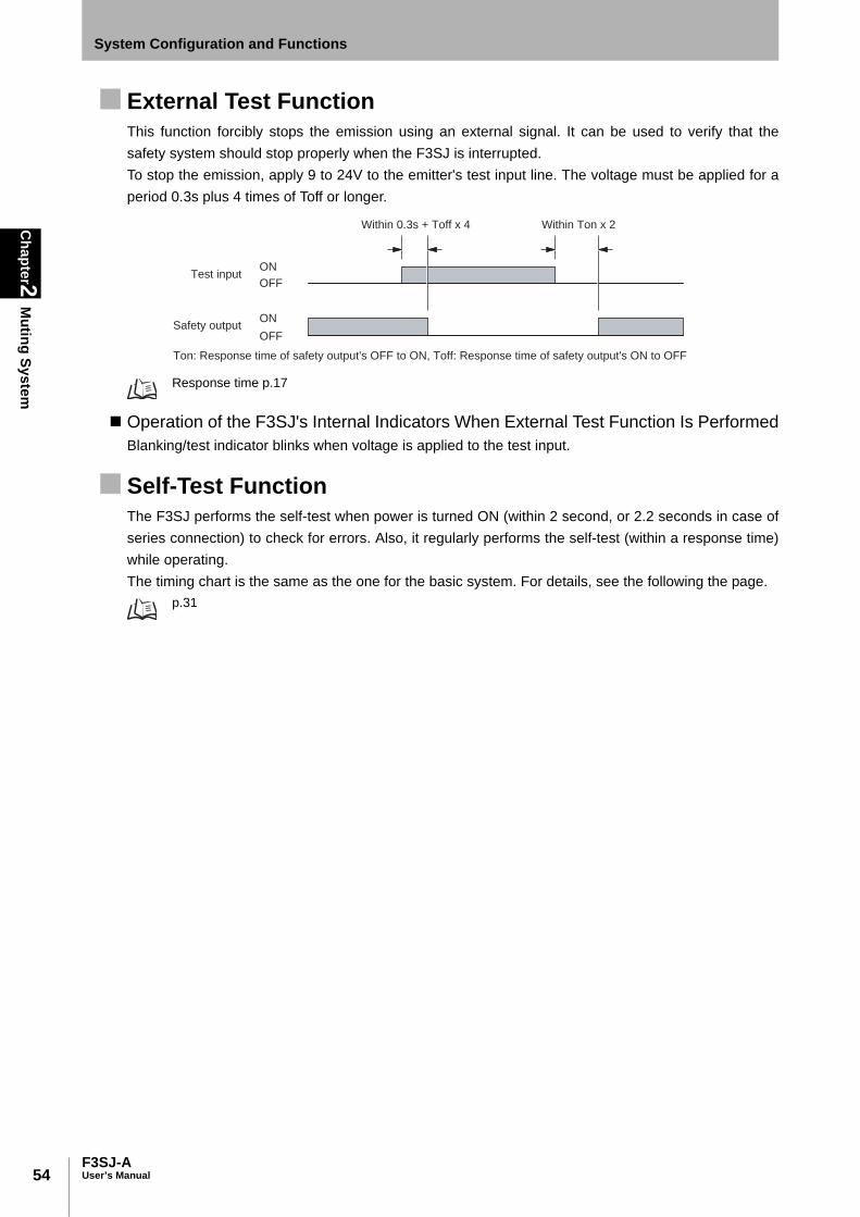
54
Chapter2
Muting System
F3SJ-AUser’s Manual
System Configuration and Functions
External Test Function This function forcibly stops the emission using an external signal. It can be used to verify that thesafety system should stop properly when the F3SJ is interrupted.To stop the emission, apply 9 to 24V to the emitter's test input line. The voltage must be applied for aperiod 0.3s plus 4 times of Toff or longer.
Response time p.17
Operation of the F3SJ's Internal Indicators When External Test Function Is PerformedBlanking/test indicator blinks when voltage is applied to the test input.
Self-Test FunctionThe F3SJ performs the self-test when power is turned ON (within 2 second, or 2.2 seconds in case ofseries connection) to check for errors. Also, it regularly performs the self-test (within a response time)while operating.The timing chart is the same as the one for the basic system. For details, see the following the page.
p.31
Test input
Safety output
Within 0.3s + Toff x 4 Within Ton x 2
Ton: Response time of safety output's OFF to ON, Toff: Response time of safety output's ON to OFF
ON
OFF
ON
OFF

55F3SJ-A
User’s Manual
Chapter2
Muting System
System Configuration and Functions
E
Auxiliary Output (Non-Safety Output)The auxiliary output is used to monitor the status of the F3SJ. This output can be connected to adevice such as a relay, indication lamp, programmable controller, etc.
Do not use the auxiliary output or external indicator output for safety applications. Human body may not be detected when F3SJ fails, resulting in serious injury.
Auxiliary output 1 provides an inverted signal of the safety output. (Factory Shipment) To connect amuting lamp to the auxiliary output 1, use the setting tool to configure output operation mode as"muting/override information" and connect it to the auxiliary output 1.
Ton: Response time of safety output's OFF to ON, Toff: Response time of safety output's ON to OFFResponse time p.17
Setting Change by the Setting ToolOutput operation mode and other attributes can be changed for the auxiliary output by the setting tool.
See p.95 for details.
Resetting LockoutWhen the cause of the lockout is removed, the lockout condition can be released by using either of thefollowing methods.•Cycle the power back ON•Set the reset input line open or to 0 to 1.5V for 100ms or longer, and then apply 9 to 24V again.
Lockout due to a muting wiring error and an ABC blinking error may not be released by a reset input.
External Device Monitoring Function (EDM)This function detects malfunctions, such as welding, in external relays (or contactors) that control thehazardous zone of a machine. The timing chart is the same as that for the basic system. For details, refer to the page shown below.
External Device Monitoring Function p.34
For the wiring diagram, refer to the page shown below.Wiring Diagrams p.40
ON
OFF
ON
OFF
Toff
/Blocked
Unblocked
Blocked
Unblocked
Auxiliary output 1
Safety output
Toff x2 or less *1
Ton
Toff x2 or less *1
*1 When a reversed signal of safety output is assigned to the auxiliary output 2 by the setting tool,
a delay time of the auxiliary output 2 from the safety output is Toff x 3 or less.

56
Chapter2
Muting System
F3SJ-AUser’s Manual
System Configuration and Functions
Operation of the F3SJ's Internal Indicator When Using the External Device Monitoring FunctionThe internal indicator cannot be used to check the input to the external device monitoring input.

Chapter3
What can be done by the setting tool
57F3SJ-A
User’s Manual
E
Chapter3 What can be done by thesetting tool
Using the Setting Tool 58
Preparation 61
F3SJ Status When Setting Tool Is Connected 63
Protection of Setting by Password 65
Setting Adjusted to Application 66
Fixed Blanking Function 66Floating Blanking Function 70Warning Zone Function 78Muting Function 81Override Function 92Setting Zone Adjacent Conditions 92
Indicator/Input & Output Setting 95
Auxiliary Output (Non-Safety Output) 95Designated Beam Output Function 97External Indicator Output (Non-Safety Output) 99Interlock Function 100External Device Monitoring Function 102
Operating Range Change 103
Operating Range Change Function 103Operation Monitoring 104
Incident Light Level Display 104Disturbance Light Level Display 104Status Information Display 105
Maintenance Information 106
Error History 106Power-on Time 106Load Switching Frequency 108
Setting Recovery 109
Other 110

58
Chapter3
Using the Setting Tool
F3SJ-AUser’s Manual
What can be done by the setting tool
Using the Setting ToolYou can change and check setting of F3SJ‘s various settings if you purchase a setting tool (optionalaccessory) described below.• Setting Console F39-MC21• PC Tool for F3SJ F39-GWUM
F3SJ must be installed, configured, and incorporated into a machine control system by a sufficiently trained and qualified person. Incorrect setting may cause a person to go undetected, resulting in serious injury.
F3SJ VersionThe setting tool can be used for F3SJ of version 2 or later, but cannot be used for that of version 1.Or, if any one of series connected F3SJs is version 1, the setting tool cannot be used (communicationerror should occur).Please note that the setting tool does not upgrade the version of the F3SJ.
Confirm the version on F3SJ label, as shown in the diagram below.
Year :
Serial No. : Version :
OMRON Corporation Kyoto, JAPAN
Location of the label describing the F3SJ version
Emitter
Receiver
Enlarged view of area enclosed by dotted line
: Serial No.
: Year of manufacture
: F3SJ version (Make sure it is version 2 or later.)
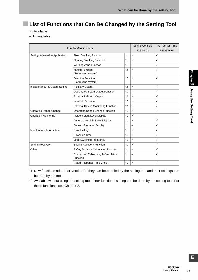
59F3SJ-A
User’s Manual
Chapter3
Using the Setting Tool
What can be done by the setting tool
E
List of Functions that Can Be Changed by the Setting Tool: Available–: Unavailable
*1 New functions added for Version 2. They can be enabled by the setting tool and their settings canbe read by the tool.
*2 Available without using the setting tool. Finer functional setting can be done by the setting tool. Forthese functions, see Chapter 2.
Function/Monitor ItemSetting Console PC Tool for F3SJ
F39-MC21 F39-GWUM
Setting Adjusted to Application Fixed Blanking Function *1
Floating Blanking Function *1
Warning Zone Function *1
Muting Function(For muting system)
*2
Override Function(For muting system)
*2
Indicator/Input & Output Setting Auxiliary Output *2
Designated Beam Output Function *1 –
External Indicator Output *2
Interlock Function *2
External Device Monitoring Function *2
Operating Range Change Operating Range Change Function *1
Operation Monitoring Incident Light Level Display *1
Disturbance Light Level Display *1
Status Information Display *1 –
Maintenance Information Error History *1
Power-on Time *1
Load Switching Frequency *1
Setting Recovery Setting Recovery Function *1
Other Safety Distance Calculation Function *1 –
Connection Cable Length Calculation Function
*1 –
Rated Response Time Check *1
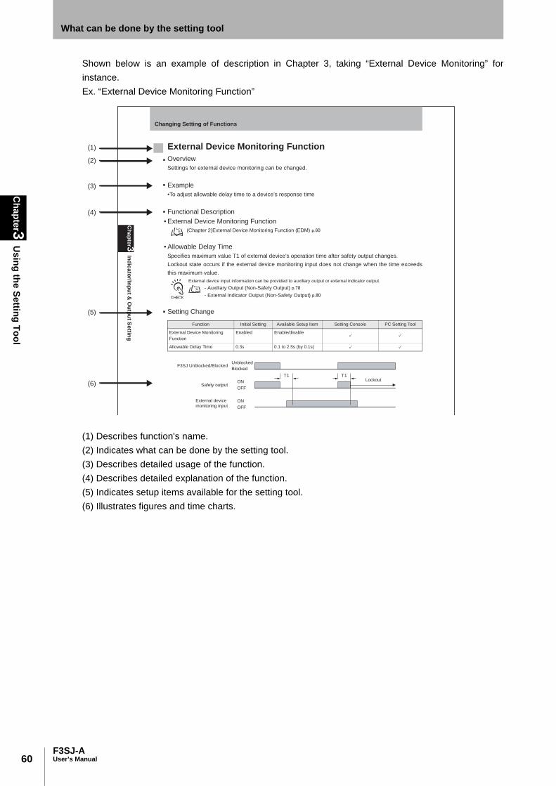
60
Chapter3
Using the Setting Tool
F3SJ-AUser’s Manual
What can be done by the setting tool
Shown below is an example of description in Chapter 3, taking “External Device Monitoring” forinstance.Ex. “External Device Monitoring Function”
(1) Describes function's name.(2) Indicates what can be done by the setting tool.(3) Describes detailed usage of the function.(4) Describes detailed explanation of the function.(5) Indicates setup items available for the setting tool.(6) Illustrates figures and time charts.
(1)
(2)
(3)
(4)
(5)
(6)
Ch
ap
ter3
Ind
ica
tor/In
pu
t & O
utp
ut S
ettin
g
Changing Setting of Functions
External Device Monitoring Function
Overview
Settings for external device monitoring can be changed.
Example
•To adjust allowable delay time to a device’s response time
Functional Description
• External Device Monitoring Function
(Chapter 2)External Device Monitoring Function (EDM)
• Allowable Delay Time
Specifies maximum value T1 of external device’s operation time after safety output changes.
Lockout state occurs if the external device monitoring input does not change when the time exceeds
this maximum value.
External device input information can be provided to auxiliary output or external indicator output.
- Auxiliary Output (Non-Safety Output)
- External Indicator Output (Non-Safety Output)
Setting Change
Function Initial Setting Available Setup Item Setting Console PC Setting Tool
External Device Monitoring
Function
Enabled Enable/disable
Allowable Delay Time 0.3s 0.1 to 2.5s (by 0.1s)
� �
� �
Safety outputON
OFF
External device
monitoring inputON
OFF
F3SJ Unblocked/BlockedUnblocked
Blocked
LockoutT1 T1
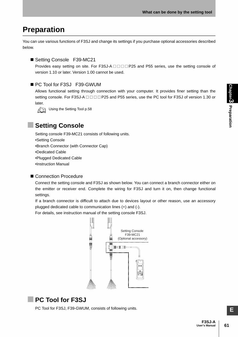
61F3SJ-A
User’s Manual
Chapter3
PreparationWhat can be done by the setting tool
E
PreparationYou can use various functions of F3SJ and change its settings if you purchase optional accessories describedbelow.
Setting Console F39-MC21Provides easy setting on site. For F3SJ-A□□□□P25 and P55 series, use the setting console ofversion 1.10 or later. Version 1.00 cannot be used.
PC Tool for F3SJ F39-GWUMAllows functional setting through connection with your computer. It provides finer setting than thesetting console. For F3SJ-A□□□□P25 and P55 series, use the PC tool for F3SJ of version 1.30 orlater.
Using the Setting Tool p.58
Setting ConsoleSetting console F39-MC21 consists of following units.•Setting Console•Branch Connector (with Connector Cap)•Dedicated Cable•Plugged Dedicated Cable•Instruction Manual
Connection ProcedureConnect the setting console and F3SJ as shown below. You can connect a branch connector either onthe emitter or receiver end. Complete the wiring for F3SJ and turn it on, then change functionalsettings.If a branch connector is difficult to attach due to devices layout or other reason, use an accessoryplugged dedicated cable to communication lines (+) and (-).For details, see instruction manual of the setting console F3SJ.
PC Tool for F3SJPC Tool for F3SJ, F39-GWUM, consists of following units.
Setting Console
F39-MC21
(Optional accessory)

62
Chapter3
Preparation
F3SJ-AUser’s Manual
What can be done by the setting tool
•CD-ROM (Setting software SD Manager and communication unit driver)•Communication Unit•Branch Connector (with Connector Cap)•Dedicated cable•Plugged Dedicated Cable•Instruction Manual (Installation Guide)It allows a user to check F3SJ's operation status and change functional settings in the setting softwareSD Manager.
Connection ProcedureConnect your computer, communication unit, and F3SJ as shown below. You can connect a branchconnector either on the emitter or receiver end. Complete the wiring for F3SJ and turn it on, thenactivate the setting software.If a branch connector is difficult to attach due to devices layout or other reason, use an accessoryplugged dedicated cable to communication lines (+) and (-).For details, see the help for the SD Manager.
Minimum Wiring for SettingMinimum wiring required to check the operation of the F3SJ(Wiring for auto reset mode and deactivated external device monitoring function)
PC
PC Tool for F3SJ
F39-GWUM
(Optional accessory)
Inte
rlo
ck s
ele
ctio
n in
pu
t(W
hite
)
0V
(Blu
e)
Shi
eld
Op
en
Op
en
Op
en
Op
en
Op
en
+24V DC
0V
Powersupply
Em
itte
r
Receiv
er
(Grey)Communication line (+)
(Pink) Communication line (-)
Shi
eld
Au
xili
ary
ou
tpu
t 2
(Re
d)
Te
st
inp
ut(
Gre
en
)
Re
se
t in
pu
t(Y
ello
w)
24
V(B
row
n)
24
V(B
row
n)
Exte
rnal devic
e m
onitoring input (R
ed)
Auxili
ary
outp
ut 1(Y
ello
w)
0V
(Blu
e)
Safe
ty o
utp
ut 1(G
reen)
Safe
ty o
utp
ut 2(W
hite)

63F3SJ-A
User’s Manual
Chapter3
F3SJ Status When Setting Tool Is C
onnectedWhat can be done by the setting tool
E
F3SJ Status When Setting Tool Is Connected
Maintenance StatusConnecting setting tool turns F3SJ into maintenance status, allowing change of setting, operationmonitoring, and check of maintenance information.Under the maintenance status, F3SJ operates as shown below:•Safety output keeps OFF status.•Indication statuses of internal indicator ON/OFF are partly different.(See below)•Lockout does not occur except for model error, communications error, setting value error, or internalcircuit failure.(For example, lockout does not occur even if a fixed blanking beam receives light)
Internal Indicators During Maintenance StatusWhen in the maintenance status, the emitter-side POWER indicator [POWER] and the receiver-sideON or OFF indicator ([ON] or [OFF]) blink.If the F3SJ is ON during normal operation, the ON output indicator blinks in the maintenance status.The safety output is OFF.If the F3SJ is OFF during normal operation, the OFF output indicator blinks and the safety output isOFF in the maintenance status.
Apparent output is ON
(Safety output is OFF)
Apparent output is OFF
(Safety output is OFF)
Emitter Receiver Emitter Receiver
Blinking
OFF
ON, blinking, or OFF,
depending on settings
POWER
INTLK
EDM
BLANKING
(TEST)
ON
OFF POWER
INTLK
EDM
BLANKING
(TEST)
ON
OFF
EM
ITT
ER
EM
ITT
ER
RE
CE
IVE
R
RE
CE
IVE
R

64
Chapter3
F3SJ Status When Setting Tool Is C
onnected
F3SJ-AUser’s Manual
What can be done by the setting tool
Internal Indicator While Writing/Monitoring with the SettingToolWhen using the setting tool to write settings to the F3SJ or while monitoring the incident light levelindicator, the [BLANKING (TEST)] indicator and an indicator on receiver's power connector side (seebelow) blink.When accessing at the administrator level, the indication lamps blink twice per second, and whenaccessing at user level, they blink once per second.
For details about administrator level and user level, see p.65
While writing/monitoring with setting tool (Safety output is OFF)
Emitter Receiver
Administrator level: Blinks twice
User level: Blinks once
OFF
POWER
INTLK
EDM
BLANKING(TEST)
ON
OFF
EM
ITT
ER
RE
CE
IVE
R
65F3SJ-A
User’s Manual
Chapter3
Protection of Setting by Password
What can be done by the setting tool
E
Protection of Setting by Password
Access QualificationThe setting tool has the following two access levels: a user level, in which setting information can onlybe read out, and an administrator level, in which functional settings can be changed.The administrator level requires a password to log in. The initial password for administrator login is"0000".
Password ChangeAn administrator must change the password to prevent setting change by an operator.Up to 4 (uppercase for alphabet) and 6 (lower and uppercase for alphabet) digits passwords can be setfor the setting console and PC tool for F3SJ respectively.
- If a password of 5 digits or more, or that includes lowercase alphabet, is set for the PC tool for F3SJ, a user cannotlog in by the setting console. If you want to use both of the PC tool for F3SJ and the setting console, you must use 4-digit alphanumeric characters (uppercase) for your password.
- A password must be alphanumeric characters.
If You Forget the Password:If you forget the password after changing it from the initial setting, contact your sales representativewith the serial number on the F3SJ receiver's label.A master password will be issued to reset to the initial password “0000”.
Location of serial number p.58

66
Chapter3
Setting Adjusted to A
pplication
F3SJ-AUser’s Manual
What can be done by the setting tool
Setting Adjusted to Application
Fixed Blanking Function Overview
Disables F3SJ’s specified beams.
Install protective structure for all zones of disabled zone so that a worker should not be able to approach hazardous zone of a machine without passing through zones disabled by the fixed blanking function.Otherwise it may result in serious injury.
If allowable beams are designated for fixed blanking, detection capability gets larger near an object that interrupts beams. Calculate a safety distance based on the setting.
You must ensure that a test rod should be detected in all zones where it should be detected after setting the fixed blanking function. Failure to do so may result in serious injury.
Example•A belt conveyor must be ignored which always sits in a detection zone.
Functional Description• Fixed Blanking Function
A function that disables a part of F3SJ's detection zone. Safety output will be kept ON status even if anobject exists in the disabled zone.For beams with fixed blanking designation, one zone is set for beams in concatenation, and up to 5zones can be set as fixed blanking zones.
• Fixed Blanking Zone SettingAn zone for fixed blanking zone must be configured. It is possible to perform teaching and set thedesignated beams manually with the interrupting object placed in the appropriate position. In thisexample shown below, the 5th and 10th beams are set as bottom and top beams respectively.
- Upper Beams: Indicate beams on F3SJ’s terminal. Lower Beams: Indicate beams on F3SJ’s power supply end.- Only one zone can be configured as a fixed blanking zone by the setting console.- Up to 5 zones can be configured as fixed blanking zones by the PC tool for F3SJ.- To reconfigure F3SJ, for which multiple zones have been already configured by the PC tool for F3SJ, settingrecovery (to factory shipment setting) must be executed before the reconfiguration. To configure multiple zones, use the PC tool for F3SJ.
Fixed blanking zone
10th beam
5th beam
Upper Upper
Lower Lower
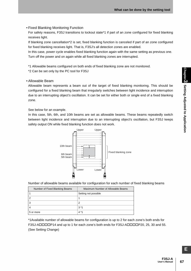
67F3SJ-A
User’s Manual
Chapter3
Setting Adjusted to A
pplicationWhat can be done by the setting tool
E
• Fixed Blanking Monitoring FunctionFor safety reasons, F3SJ transitions to lockout state*1 if part of an zone configured for fixed blankingreceives light.If blanking zone cancellation*2 is set, fixed blanking function is canceled if part of an zone configuredfor fixed blanking receives light. That is, F3SJ’s all detection zones are enabled.In this case, power cycle enables fixed blanking function again with the same setting as previous one.Turn off the power and on again while all fixed blanking zones are interrupted.
*1 Allowable beams configured on both ends of fixed blanking zone are not monitored.*2 Can be set only by the PC tool for F3SJ
• Allowable BeamAllowable beam represents a beam out of the target of fixed blanking monitoring. This should beconfigured for a fixed blanking beam that irregularly switches between light incidence and interruptiondue to an interrupting object’s oscillation. It can be set for either both or single end of a fixed blankingzone.
See below for an example.In this case, 5th, 6th, and 10th beams are set as allowable beams. These beams repeatedly switchbetween light incidence and interruption due to an interrupting object's oscillation, but F3SJ keepssafety output ON while fixed blanking function does not work.
Number of allowable beams available for configuration for each number of fixed blanking beams
*1Available number of allowable beams for configuration is up to 2 for each zone’s both ends for F3SJ-AP14 and up to 1 for each zone’s both ends for F3SJ-AP20, 25, 30 and 55.(See Setting Change)
Number of Fixed Blanking Beams Maximum Number of Allowable Beams
1 Setting not possible
2 1
3 2
4 3 *1
5 or more 4 *1
Fixed blanking zone
10th beam
6th beam5th beam
Upper Upper
Lower Lower

68
Chapter3
Setting Adjusted to A
pplication
F3SJ-AUser’s Manual
What can be done by the setting tool
For detection capability when allowable beam is configured, see next table.Detection capability for allowable beam configuration [mm]
• Internal Indicators of F3SJFor basic system: When fixed blanking function is enabled, emitter's BLANKING/TEST indicator isturned on.For muting system: When fixed blanking function is enabled, receiver's BLANKING/TEST indicator isturned on.
Setting ChangeConfigure for each CH in case of a series connection.
*1 When a fixed blanking zone with 3 beams or more is configured by the setting console, allowablebeams are automatically configured.For a fixed blanking zone with 2 beams or less, allowable beams are not configured. For details, seeinstruction manual of the setting console.
With the PC tool for F3SJ, perform the same settings for fixed blanking zones 2 to 5.
Allowable BeamF3SJ-A
P14F3SJ-A
P20F3SJ-A
P25F3SJ-A
P30F3SJ-A
P55
Disable 14 20 25 30 55
Lower 1 beam is enabled 23 35 45 55 105
Upper 1 beam is enabled
Lower 1 beam and upper 1 beam are enabled
Lower 2 beams are enabled 32 - - - -
Upper 2 beams are enabled
Lower 2 beams and upper 1 beam are enabled
Lower 1 beam and upper 2 beams are enabled
Lower 2 beams and upper 2 beams are enabled
Function Initial Setting Available Setup ItemSetting
ConsolePC Tool For
F3SJ
Fixed Blanking Function Disable Disable/Enable
Fixed Blanking Zone Bottom Beam 0 1 to Number of Beams
Fixed Blanking Zone Top Beam 0 1 to Number of Beams
Fixed Blanking Monitoring Function Lockout Lockout/Blanking Zone Cancellation
– (lockout only)
Allowable Beam Disable See table above – *1

69F3SJ-A
User’s Manual
Chapter3
Setting Adjusted to A
pplicationWhat can be done by the setting tool
E
Restriction Condition between Fixed Blanking ZonesMore than one fixed blanking zone can be configured adjacently (Figures 1 and 2). But allowablebeams cannot be set adjacently. (Figure 3)You cannot overlap fixed blanking zones. (Figure 4)
Limitation for Combination with Other FunctionsYou can use this function in combination with muting, floating blanking, and warning zone functions atthe same time with the PC tool for F3SJ. The setting console can be combined with muting function.For both setting tools, there is a limitation for setting with zones.For details, see Setting Zone Adjacent Conditions p.92 .
Setting Zone Adjacent Conditions p.92
Normal detecting beam
Fixed blanking beam
Allowable beam
Figure 4Figure 3
Figure 1 Figure 2
Fixed blanking zone 1
Fixed blanking zone 2
Fixed blanking zone 1
Fixed blanking zone 2
Fixed blanking zone 1
(Lower 1 allowable beam)
Fixed blanking zone 1
(Lower 1 allowable beam)
Fixed blanking zone 2
(Upper 1 allowable beam)
Fixed blanking zone 2
Upper Upper
UpperUpper
Lower Lower
LowerLower
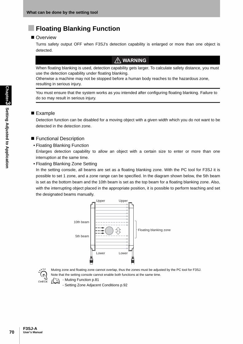
70
Chapter3
Setting Adjusted to A
pplication
F3SJ-AUser’s Manual
What can be done by the setting tool
Floating Blanking Function Overview
Turns safety output OFF when F3SJ’s detection capability is enlarged or more than one object isdetected.
When floating blanking is used, detection capability gets larger. To calculate safety distance, you must use the detection capability under floating blanking.Otherwise a machine may not be stopped before a human body reaches to the hazardous zone, resulting in serious injury.
You must ensure that the system works as you intended after configuring floating blanking. Failure to do so may result in serious injury.
ExampleDetection function can be disabled for a moving object with a given width which you do not want to bedetected in the detection zone.
Functional Description• Floating Blanking Function
Enlarges detection capability to allow an object with a certain size to enter or more than oneinterruption at the same time.
• Floating Blanking Zone SettingIn the setting console, all beams are set as a floating blanking zone. With the PC tool for F3SJ it ispossible to set 1 zone, and a zone range can be specified. In the diagram shown below, the 5th beamis set as the bottom beam and the 10th beam is set as the top beam for a floating blanking zone. Also,with the interrupting object placed in the appropriate position, it is possible to perform teaching and setthe designated beams manually.
Muting zone and floating zone cannot overlap, thus the zones must be adjusted by the PC tool for F3SJ.Note that the setting console cannot enable both functions at the same time.
- Muting Function p.81 - Setting Zone Adjacent Conditions p.92
Floating blanking zone
10th beam
5th beam
Upper
Lower
Upper
Lower

71F3SJ-A
User’s Manual
Chapter3
Setting Adjusted to A
pplicationWhat can be done by the setting tool
E
• Floating BeamBased on floating beam count setting, settings shown below do not turn OFF safety output as shownbelow. Measure the size (maximum diameter) of the interrupting object, and set a number of floatingbeams so that the size of the interrupting object is less than the dimensions in the graph.
Setting Example: For F3SJ-AP14 with an interrupting object of diameter 20mm, set number offloating beams as 3. With this setting, F3SJ will not turn OFF safety output even if an object with adiameter of 22mm or less is in the floating blanking zone.Valid Range for number of Floating Beams
Available range for floating
0 10 20 30 40
Number of floating beams : 4
Number of floating beams : 3
Number of floating beams : 2
Number of floating beams : 1
Interrupting object diameter [mm]
Available range for setting413
2231
F3SJ-AP14 series
Available range for floating
0 10 20 30 40 50 60
Number of floating beams : 4
Number of floating beams : 3
Number of floating beams : 2
Number of floating beams : 1
Interrupting object diameter [mm]
Available range for setting1025
4055
F3SJ-AP20 series
Available range for floating
0 10 20 30 40 50 60 70 80
Number of floating beams : 4
Number of floating beams : 3
Number of floating beams : 2
Number of floating beams : 1
Interrupting object diameter [mm]
Available range for setting1535
5575
F3SJ-AP25 series
Available range for floating
0 10 20 30 40 50 60 70 80 90 100
Number of floating beams : 4
Number of floating beams : 3
Number of floating beams : 2
Number of floating beams : 1
Interrupting object diameter [mm]
Available range for setting2045
7095
F3SJ-AP30 series

72
Chapter3
Setting Adjusted to A
pplication
F3SJ-AUser’s Manual
What can be done by the setting tool
• Floating Blanking Monitoring Function (Sequential Beam Mode Only)F3SJ monitors an interrupting object in a floating blanking zone. (If the object is removed or getssmaller, human entry may not be detected by F3SJ, resulting in serious injury)F3SJ enters lockout when an interrupting object is removed.For F3SJ’s operation when an interrupting object is removed, setting is available from disablingmonitoring function*1.By setting allowable beams, the monitoring function is enabled and lockout occurs when aninterrupting object is smaller than the value that is set.From the graph below, check number of the floating beams as well as that of allowable beams thatallow operation without putting the F3SJ into lockout or turning the control output OFF.
*1 Even if the interrupting object is removed, F3SJ will not turn OFF the output or enter lockout. Thisfunction is for PC tool for F3SJ only.
For F3SJ-AP14 with an interrupting object of diameter 20mm, following combinations areavailable.•Number of floating beams is 3, monitoring disabled•Number of floating beams is 3, monitoring enabled (number of allowable beams is 2)•Number of floating beams is 4, monitoring enabled (number of allowable beams is 3)
If number of floating beams is 3 and monitoring enabled (number of allowable beams is 2) is set, thesensor turns safety output OFF when 22mm or longer zone is interrupted, and locks out when under14mm is interrupted. (If blanking monitoring function is set to lockout)
Valid Range for number of Floating Beams(if blanking monitoring is enabled)
Available range for floating
0 20 40 60 80 100 120 140 160 180 200
Number of floating beams : 4
Number of floating beams : 3
Number of floating beams : 2
Number of floating beams : 1
Interrupting object diameter [mm]
Available range for setting4595
145 195
F3SJ-AP55 series
Available range for floating
0 10 20 30 40
Number of floating beams : 4 Number of Allowable beams : 2
Number of floating beams : 4 Number of Allowable beams : 3
Number of floating beams : 3 Number of Allowable beams : 2
Interrupting object diameter [mm]
Available range for setting
14
14
23
22
31
31
F3SJ-AP14 series
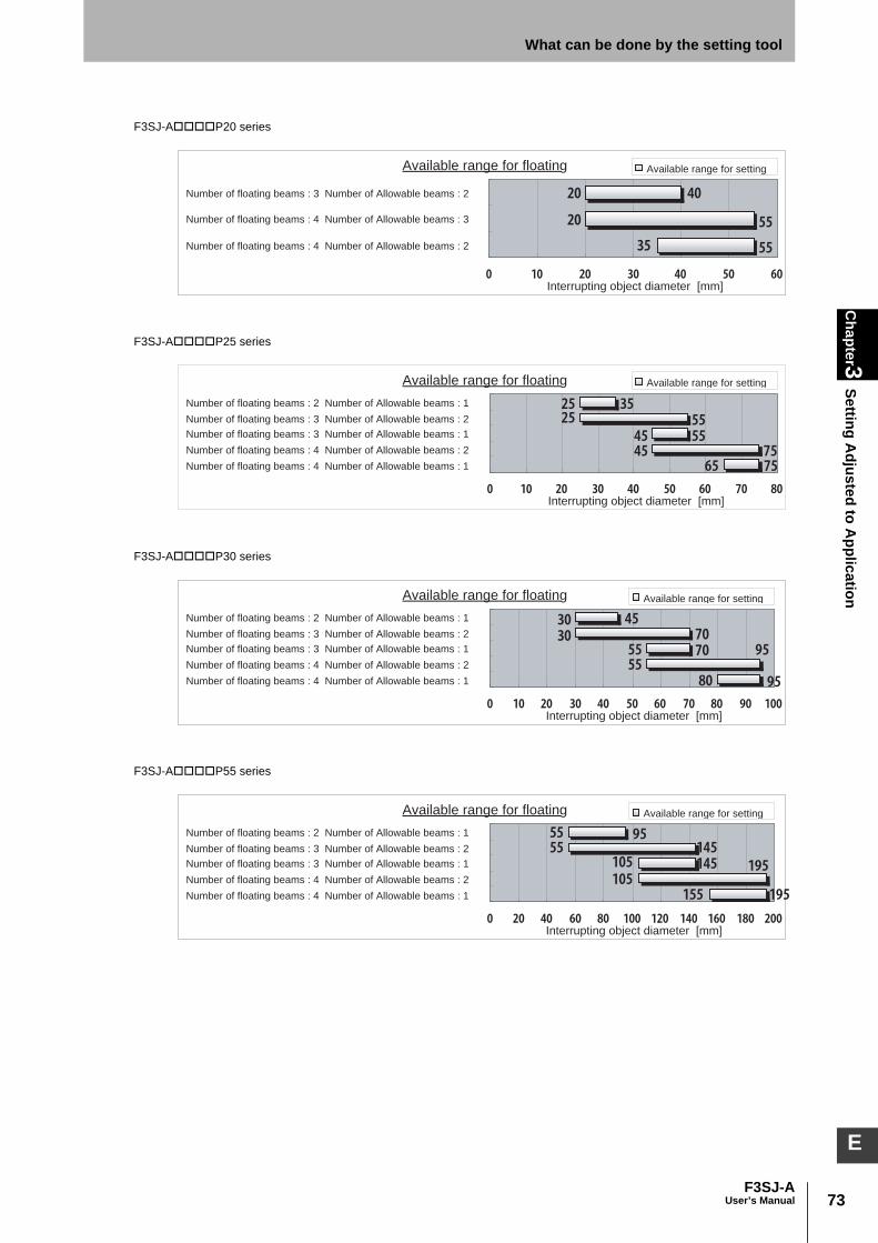
73F3SJ-A
User’s Manual
Chapter3
Setting Adjusted to A
pplicationWhat can be done by the setting tool
E
Available range for floating
0 10 20 30 40 50 60
Number of floating beams : 4 Number of Allowable beams : 2
Number of floating beams : 4 Number of Allowable beams : 3
Number of floating beams : 3 Number of Allowable beams : 2
Interrupting object diameter [mm]
Available range for setting
4020
20
3555
55
F3SJ-AP20 series
Available range for floating
0 10 20 30 40 50 60 70 80
Number of floating beams : 4 Number of Allowable beams : 1Number of floating beams : 4 Number of Allowable beams : 2Number of floating beams : 3 Number of Allowable beams : 1Number of floating beams : 3 Number of Allowable beams : 2Number of floating beams : 2 Number of Allowable beams : 1
Interrupting object diameter [mm]
Available range for setting
2525
45
355555
45 7565 75
F3SJ-AP25 series
Available range for floating
0 10 20 30 40 50 60 70 80 90 100
Number of floating beams : 4 Number of Allowable beams : 1Number of floating beams : 4 Number of Allowable beams : 2Number of floating beams : 3 Number of Allowable beams : 1Number of floating beams : 3 Number of Allowable beams : 2Number of floating beams : 2 Number of Allowable beams : 1
Interrupting object diameter [mm]
Available range for setting
3030
55
457070
5595
80 95
F3SJ-AP30 series
Available range for floating
0 20 40 60 80 100 120 140 160 180 200
Number of floating beams : 4 Number of Allowable beams : 1Number of floating beams : 4 Number of Allowable beams : 2Number of floating beams : 3 Number of Allowable beams : 1Number of floating beams : 3 Number of Allowable beams : 2Number of floating beams : 2 Number of Allowable beams : 1
Interrupting object diameter [mm]
Available range for setting
5555
105
95145145
105195
155 195
F3SJ-AP55 series

74
Chapter3
Setting Adjusted to A
pplication
F3SJ-AUser’s Manual
What can be done by the setting tool
• Floating Blanking ModeFloating blanking has the following 2 modes.1. Sequential Beam Mode2. Non-Sequential Beam Mode
1. Sequential Beam ModeIf a size of an interrupting object is specified size or smaller, safety output is not turned OFF.But if interrupting object(s) enter more than one zone of detection zone, safety output is turned OFF.Under this mode, floating blanking monitoring can be configured. (It cannot be if number of floatingbeams is 1)For minimum detection capability, see “Detection Capability”.For a size of an object which should not be detected, see “Floating Beam”.
- Floating Blanking Function p.70 - Detection Capability p.77 - Floating Beam p.71
Number of Floating Beams Number of Allowable Beams
1 Setting not possible
2 Only 1
3 1, 2
4 1, 2, 3
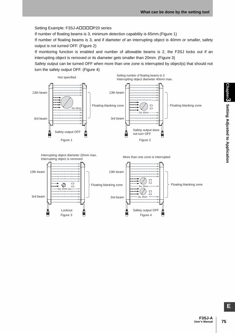
75F3SJ-A
User’s Manual
Chapter3
Setting Adjusted to A
pplicationWhat can be done by the setting tool
E
Setting Example: F3SJ-AP20 seriesIf number of floating beams is 3, minimum detection capability is 65mm.(Figure 1)If number of floating beams is 3, and if diameter of an interrupting object is 40mm or smaller, safetyoutput is not turned OFF. (Figure 2)If monitoring function is enabled and number of allowable beams is 2, the F3SJ locks out if aninterrupting object is removed or its diameter gets smaller than 20mm. (Figure 3)Safety output can be turned OFF when more than one zone is interrupted by object(s) that should notturn the safety output OFF. (Figure 4)
Safety output OFF
Not specified
Dia. 65mmFloating blanking zoneFloating blanking zone
Figure 1 Figure 2
13th beam 13th beam
3rd beam 3rd beam
Safety output does
not turn OFF
Setting number of floating beams to 3
Interrupting object diameter 40mm max.
Dia. 40mm
Lockout
Interrupting object diameter 20mm max.
Interrupting object is removedMore than one zone is interrupted
Figure 3 Figure 4
Safety output OFF
Floating blanking zone Floating blanking zone
13th beam
3rd beam
13th beam
3rd beam
Dia. 20mm max.Dia. 30mm
Dia. 30mm

76
Chapter3
Setting Adjusted to A
pplication
F3SJ-AUser’s Manual
What can be done by the setting tool
2. Non-Sequential Beam ModeWhen total number of interrupted beams in an zone reaches the designated number or more, it isevaluated as interruption.
Detection Capability p.77
• Setting ExampleIf number of floating beams is 2, safety output is not turned OFF if 3 or more beams are interrupted. If 2 or less beams are interrupted, safety output is not turned OFF. (Figure 5)If 3 or more beams are interrupted, safety output is turned OFF. (Figure 6)Even if there is only one interrupting object, safety output can be turned OFF when 3 beams areinterrupted. (Figure 7)
• Internal Indicators of F3SJFor basic system: Emitter’s BLANKING/TEST indicator is turned on under floating blanking state.For muting system: Receiver’s BLANKING/TEST indicator is turned on under floating blanking state.
3 or more beams are interrupted2 or less beams are interrupted
3th beam
13th beam
3th beam
13th beam
Figure 5 Figure 6
Floating blanking zone Floating blanking zone
Safety output OFFSafety output ON
An interrupting object blocks 3 or more beams
3th beam
13th beam
Figure 7
Floating blanking zone
Safety output OFF

77F3SJ-A
User’s Manual
Chapter3
Setting Adjusted to A
pplicationWhat can be done by the setting tool
E
Setting ChangeIn the setting console, all beams are set as a floating blanking zone. With the PC tool for F3SJ, it is possible to set a range of floating blanking zone. Configure for each CH in case of a series connection.
*1 If this function is enabled, and if either beam of F3SJ's ends is configured as a floating blankingzone, it is excluded from floating blanking zone.In figure 11, for example, bottom and top beams setting of blanking zone is ignored and a zone fromthe 2nd to 15th beams is set as a floating blanking zone.
*2 Monitoring is disabled for non-sequential beam mode.*3 To connect the setting console and F3SJ for which followings are configured, you must execute the
setting recovery on connection to recover factory shipment setting.- Blanking zone is partially set- Floating blanking monitoring function is being disabled
*4 In case of PC tool for F3SJ, other zone must be specified than outermost beams.
• Detection CapabilityDetection capability of F3SJ can differ based on number of floating beams as shown below.Minimum detection capability and number of beams for which safety output should be turned OFF
Limitation for Combination with Other FunctionsYou can use muting, fixed blanking, and warning zone functions in combination only with the PC toolfor F3SJ. Note that there is a limitation for setting with zones.The setting console cannot combine these functions.For details, see Setting Zone Adjacent Conditions p.92 .
Setting Zone Adjacent Conditions p.92
Function Initial Setting Available Setup Item Setting ConsolePC Tool For
F3SJ
Floating Blanking Function Disable Enable/disable *3
Blanking Zone Bottom Beam 0 1 to Number of Beams – (Fixed to bottom)
Blanking Zone Top Beam 0 1 to Number of Beams – (Fixed to top)
Both End Beam Disabling Mode *1 Disable Enable/disable *4
Floating Blanking Mode Sequential Beam Mode
Sequential Beam Mode/Non-Sequential Beam Mode
Number of Floating Beams 1 1~4
Number of Allowable Beams 0 0~3
Floating Blanking Monitoring Function *2 Lockout Lockout / Monitoring Disabled
–
ModelNumber of Floating Beams and Detection Capability
Not specified Setting 1 Setting 2 Setting 3 Setting 4
F3SJ-AP14 series 14 mm 23 mm 32 mm 41 mm 50 mm
F3SJ-AP20 series 20 mm 35 mm 50 mm 65 mm 80 mm
F3SJ-AP25 series 25 mm 45 mm 65 mm 85 mm 105 mm
F3SJ-AP30 series 30 mm 55 mm 80 mm 105 mm 130 mm
F3SJ-AP55 series 55 mm 105mm 155 mm 205 mm 255mm
Number of beams for which safety output is turned OFF 1 beam 2 beams 3 beams 4 beams 5 beams

78
Chapter3
Setting Adjusted to A
pplication
F3SJ-AUser’s Manual
What can be done by the setting tool
Warning Zone Function Overview
Detection zone can be divided into original detection zone and warning zone.
Warning zone output is non-safety output. You must not include it to calculation of safety distance. Otherwise safety distance may be reduced, resulting in serious injury.
A warning zone CANNOT be used for safety applications. Always install your system so that a detection zone should be passed before reaching a source of danger.
Warning zone function can be used only when F3SJ is installed horizontally. It CANNOT be used when F3SJ is installed vertically.
A warning zone must be configured based on a safety distance.
See "Safety Distance: If a person approaches the detection zone of the F3SJ perpendicularly p.115 " if a detection zone is within vertically installed F3SJ as shown left.See "Safety Distance: In case of horizontal approach of a human body to F3SJ's detection zone p.116 " if a detection zone is within horizontally installed F3SJ as shown right.
Example•When a person enters, indicator or buzzer should notify warning without stopping a machine.
Functional Description• Warning Zone Function
Incidence or interruption to a warning zone will not affect safety output operation. When an outputoperation mode of auxiliary output or external indicator output is configured as a warning zone, itsunblocked/blocked status can be output.
- Auxiliary Output (Non-Safety Output) p.95 - External Indicator Output (Non-Safety Output) p.99
Detection Zone
Warning Zone
Warning Zone
Detection
ZoneHazard
Warning Zone
Detection Zone
Detection Zone
Hazard
Safety distance (S)
Safety
distance (S)
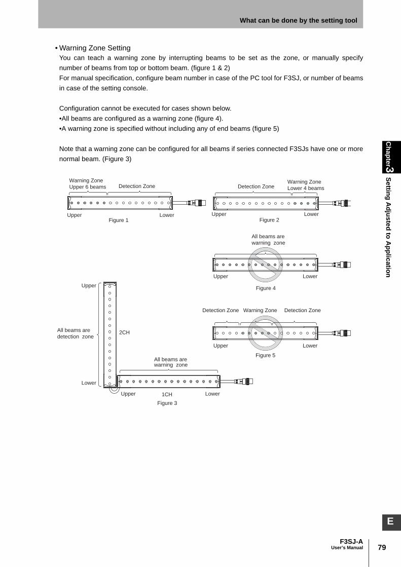
79F3SJ-A
User’s Manual
Chapter3
Setting Adjusted to A
pplicationWhat can be done by the setting tool
E
• Warning Zone SettingYou can teach a warning zone by interrupting beams to be set as the zone, or manually specifynumber of beams from top or bottom beam. (figure 1 & 2)For manual specification, configure beam number in case of the PC tool for F3SJ, or number of beamsin case of the setting console.
Configuration cannot be executed for cases shown below.•All beams are configured as a warning zone (figure 4).•A warning zone is specified without including any of end beams (figure 5)
Note that a warning zone can be configured for all beams if series connected F3SJs have one or morenormal beam. (Figure 3)
Warning Zone
Upper 6 beamsWarning Zone
Lower 4 beams
LowerUpperFigure 1
LowerUpper
LowerUpper
All beams are
warning zone
All beams are
detection zone
Figure 4
Figure 5
LowerUpperFigure 2
LowerUpper
Warning Zone
All beams are warning zone
Lower
Upper
Figure 3
Detection Zone
Detection ZoneDetection Zone
Detection Zone
2CH
1CH

80
Chapter3
Setting Adjusted to A
pplication
F3SJ-AUser’s Manual
What can be done by the setting tool
Setting Example: Configuring a warning zone information for auxiliary output 1Reverse Output: None
Setting ChangeConfigure for each CH in case of a series connection.
- If you need output of warning zone’s incidence/interruption status, set output mode of auxiliary output or externalindicator output to warning zone information.
- Auxiliary Output (Non-Safety Output) p.95 - External Indicator Output (Non-Safety Output) p.99
- A warning zone cannot overlap with muting, fixed blanking, nor floating blanking zones.
Warning Zone LabelWhen a warning zone is configured, you must attach labels that indicate a border between normaldetection zone and warning zone.
Function Initial Setting Available Setup Item Setting Console PC Tool for F3SJ
Warning Zone Function
Disable Disabled/Enabled from upper/Enabled from lower
Warning Zone Setting
0 0 to Number of Beams
Warning Zone
Detection Zone
Figure 6 Figure 7 Figure 8
Safety output ON
Warning zone output OFF
Safety output ON
Warning zone output ON
Safety output OFF
Warning zone output OFF
F3SJ Unblocked/Blocked
(Warning zone only)
F3SJ Unblocked/Blocked
(Other than warning zone)
Unblocked
Blocked
Auxiliary output 1
(warning zone)
ON
OFF
Unblocked
Blocked
Safety outputON
OFF
Warning ZoneDetection Zone
Normal beam Warning beam
DETECTIONZONE
WARNINGZONE
81F3SJ-A
User’s Manual
Chapter3
Setting Adjusted to A
pplicationWhat can be done by the setting tool
E
Limitation for Combination with Other FunctionsYou can use muting, fixed blanking, and floating blanking functions in combination only with the PCtool for F3SJ. Note that there is a limitation for setting with zones.The setting console cannot combine these functions.For details, see Setting Zone Adjacent Conditions p.92 .
Setting Zone Adjacent Conditions p.92
Muting Function Overview
Configures muting function.
The muting function disables safety functions of the device. You must ensure safety using other measures during this function is enabled.
Install muting sensors so that they can distinguish between a person and an object that is being allowed to pass through the detection zone.
All muting lamps (external indicators) that indicate state of muting function must be installed where workers can see them from all the operating positions.
Muting related time must be properly configured for its application by a sufficiently trained and qualified person, and the person must have responsibility for settings, especially when setting the muting time limit to infinite.
Use independent 2 input devices for muting input.
You must install F3SJ, muting sensor, and physical barrier, and configure time settings for muting so that an operator should not enter hazardous zone.
Example•Only workpieces should pass through a conveyor entry•Muting function should work for only a specified zone•Other muting mode should be configured than standard muting which is not suitable for your
application
Functional Description• Muting Function
Muting System p.35
• Operation ModePC tool for F3SJ allows selection of 3 operation modes for muting function:1. Standard Muting Mode2. Exit Only Muting Mode3. Position Detection Muting Mode
• Muting Zone SettingSetting tool provides designation of beams for muting. (All beams are specified for factory shipment)You can specify a beam by teaching, with which the sensor learns muting beams as those interrupted,or manually.

82
Chapter3
Setting Adjusted to A
pplication
F3SJ-AUser’s Manual
What can be done by the setting tool
Muting Zone Setting Example•Setting from F3SJ’s upper beams (figure 1)•Setting multiple zones (figure 2)
- Only one zone can be configured as a muting zone by the setting console, which cannot set more than one zone.- Interlock function is disabled for a muting system.If you want to use start or restart interlock, use the setting tool to enable the function.
Interlock Function p.100
- When muting function is enabled, a muting lamp is turned on to notify people in the surrounding zone that the safetyfunctions are disabled. Factory setup is external indicator outputs 1 and 2.While the setting tool allows change of output destination for a muting lamp, muting/override information must be setto at least one of auxiliary output 1 or external indicator outputs 1 or 2. If none of the above output is set, F3SJ enters lockout.
- Auxiliary output 1, external indicator outputs 1 and 2 have diagnosis function.For safety reason, using diagnosis function is recommended.
- Auxiliary Output (Non-Safety Output) p.95 - External Indicator Output (Non-Safety Output) p.99
1. Standard Muting ModeOperation mode configured for F3SJ factory shipment.Turning muting inputs 1 and 2 ON with time difference enables muting function.For details, see Muting in Chapter 2.
Muting System p.35
Setting can be changed, such as muting time limit.
2. Exit Only Muting Mode (Setting is Available Only for PC Tool For F3SJ)Turning muting inputs 1 and 2 ON with time difference enables muting function.Difference from standard mode exists in muting completion condition.
• Start ConditionsIf both of the following 2 conditions are present, muting is activated.1. No interrupting object is found in the F3SJ's detection zone, and safety output is ON.2. After muting input 1 is turned ON (connected to 9 to 24V), muting input 2 is turned ON (connected to
9 to 24V) within the muting input time limit of T1min to T1max (0.03 to 3s: can be changed).
Lower
Upper
Lower
Upper
Muting zoneMuting zone
Muting zone
Normal detecting beam
Muting beamsFigure 1 Figure 2

83F3SJ-A
User’s Manual
Chapter3
Setting Adjusted to A
pplicationWhat can be done by the setting tool
E
When condition 1 is satisfied but time condition of 2 is not, a muting sequence error occurs andreceiver’s muting error indicator turns ON.A muting error is canceled when either of the following condition is satisfied.•Muting is started by a proper muting sequence.•Power cycle under muting input 1 and 2 OFF state.
• End ConditionsIf either of the following condition is satisfied, muting state will be released.•When a workpiece passed a muting sensor 1 or 2 and muting delay time dedicated to exit (4s: can be
changed) passed.•When a workpiece passed F3SJ’s detection zone and muting waiting time(0.1s) passed.•Muting continuance time exceeds muting time limit (60s: can be changed).•When a muting beam is not blocked within muting input time limit T1max (maximum) after the muting
input 2 is turned ON.Muting state can be also released when the sensor enters lockout.
• For Override FunctionThe override function is unavailable for the exit only muting mode.
• For WiringSame as standard muting.
Chapter 2 Muting System p.35
• Installation Example of Exit Only Muting ModeThis is an installation example of exit only muting mode. When exit only muting mode is set, install themuting sensor on the hazardous side of the workpiece exit.This can be used if a workpiece has a certain length and the hazardous side of the workpiece exit hasenough space around it.
1. Before a workpiece passes through
All muting sensors are turned OFF and the safety function of the F3SJ is working.
Workpiece
F3SJA1 B1
Hazardous zone
A1 : Muting sensor to be connected
to muting input 1
B1 : Muting sensor to be connected
to muting input 2
V
d2
d1

84
Chapter3
Setting Adjusted to A
pplication
F3SJ-AUser’s Manual
What can be done by the setting tool
2. The muting sensor is blocked and the safety function of the F3SJ is disabled
When muting sensors A1 and B1 are turned ON in this order, and the muting function is enabled. Inthis state, the safety function of F3SJ is disabled.
3. Muting sensor A1 is turned OFF
A workpiece finished passing the muting sensor A1 and the sensor starts turning OFF. For standardmuting system, muting is released here. For exit only muting, F3SJ's safety function is disabled for aexit only muting delay time: T5.
4. Muting sensor B1 is turned OFF
A workpiece finished passing the muting sensor B1 and the sensor is turned OFF. F3SJ disables itssafety function if it is within a exit only muting delay time.
Workpiece
F3SJA1 B1
Hazardous zone
A1 : Muting sensor to be connected
to muting input 1
B1 : Muting sensor to be connected
to muting input 2
V
d2
d1
VWorkpiece
F3SJA1 B1
Hazardous zone
A1 : Muting sensor to be connected
to muting input 1
B1 : Muting sensor to be connected
to muting input 2
d2
d1
Workpiece
F3SJA1 B1
Hazardous zone
A1 : Muting sensor to be connected
to muting input 1
B1 : Muting sensor to be connected
to muting input 2
V
d2
d1
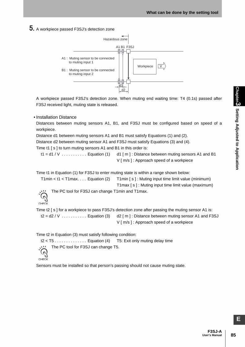
85F3SJ-A
User’s Manual
Chapter3
Setting Adjusted to A
pplicationWhat can be done by the setting tool
E
5. A workpiece passed F3SJ’s detection zone
A workpiece passed F3SJ’s detection zone. When muting end waiting time: T4 (0.1s) passed afterF3SJ received light, muting state is released.
• Installation DistanceDistances between muting sensors A1, B1, and F3SJ must be configured based on speed of aworkpiece.Distance d1 between muting sensors A1 and B1 must satisfy Equations (1) and (2).Distance d2 between muting sensor A1 and F3SJ must satisfy Equations (3) and (4).Time t1 [ s ] to turn muting sensors A1 and B1 in this order is:
t1 = d1 / V . . . . . . . . . . . Equation (1) d1 [ m ] : Distance between muting sensors A1 and B1V [ m/s ] : Approach speed of a workpiece
Time t1 in Equation (1) for F3SJ to enter muting state is within a range shown below:T1min < t1 < T1max. . . . Equation (2) T1min [ s ] : Muting input time limit value (minimum)
T1max [ s ] : Muting input time limit value (maximum)The PC tool for F3SJ can change T1min and T1max.
Time t2 [ s ] for a workpiece to pass F3SJ’s detection zone after passing the muting sensor A1 is: t2 = d2 / V . . . . . . . . . . . Equation (3) d2 [ m ] : Distance between muting sensor A1 and F3SJ
V [ m/s ] : Approach speed of a workpiece
Time t2 in Equation (3) must satisfy following condition:t2 < T5 . . . . . . . . . . . . . . Equation (4) T5: Exit only muting delay time
The PC tool for F3SJ can change T5.
Sensors must be installed so that person’s passing should not cause muting state.
Workpiece
F3SJA1 B1
Hazardous zone
A1 : Muting sensor to be connected
to muting input 1
B1 : Muting sensor to be connected
to muting input 2
V
d2
d1

86
Chapter3
Setting Adjusted to A
pplication
F3SJ-AUser’s Manual
What can be done by the setting tool
Also, muting sensors and F3SJ must be installed so that muting state caused by a workpiece shouldbe ended before the next workpiece arrives at the first muting sensor.
Timing Chart
*1 The value is applied to a single sensor. Values for connected sensors are:
•T1min: Muting input time limit value (minimum)Minimum time difference between muting inputs 1 and 2.If the time difference between muting inputs 1 and 2 is smaller than this value, a muting error occurs.
•T1max: Muting input time limit value (maximum)Maximum time difference between muting inputs 1 and 2.Minimum value must be less than maximum value.
•T2: Muting time limitTime to be continued for muting function. If muting state exceeds this time, the function is canceled.
•T3: Maximum muting input time with allowable waveform cracks
# of connections *1 Value (s)
Single 0.15
2 connected 0.26
3 connected 0.29
4 connected 0.32
Workpiece Workpiece Workpiece Workpiece
F3SJA1 B1 F3SJA1 B1
Hazardous zone Hazardous zone
d2
d1
d2
d1
Moving direction Moving direction
T2 max.
0.15s max. *1
T5 max.
Muting input 1
(Muting sensor A1)ON
OFF
Muting input 2
(Muting sensor B1)
F3SJ Unblocked
/Blocked
Unblocked
Blocked
Safety output
ON
OFF
ON
OFF
Muting stateEnabled
Disabled
Muting lampBlinking
OFF
T1max
T4 (0.1s)
T1min to T1max
T3 (0.1s) max.
T3(0.1s) max.

87F3SJ-A
User’s Manual
Chapter3
Setting Adjusted to A
pplicationWhat can be done by the setting tool
E
Indicates maximum time limit to allow waveform cracks regarding the muting input 1 and mutinginput 2 in the effective muting state. It is set as 0.1s.
•T4: Muting end waiting timeOFF delay time from F3SJ’s light incidence to release of muting state. It is set as 0.1s.
•T5: Exit only muting delay timeOFF delay time from muting input 1 or 2’s signal turning OFF to release of muting state.
If either of the following conditions are present, muting ended. In this timing chart, T4(0.1s) condition releases themuting state.
1. When exit only muting delay time T5 exceeds the setting value.2. When a workpiece passed F3SJ’s detection zone and muting waiting time T4(0.1s) passed.3. When muting continuance time exceeds muting time limit T2.
3. Position Detection Muting Mode (Setting is Available only for PC Tool For F3SJ)Muting function is enabled when muting input 1 turns ON from OFF and muting input 2 turns OFF fromON within the input time difference T1max, measured by a limit switch, etc. Muting inputs must beheterogeneous redundant inputs such as N.O. contact and N.C. contact types. (In case of PNP outputtype photoelectric sensor, use one by L/ON operation while the other by D/ON) This can be used for such a case that F3SJ should be temporarily disabled as the switch is sooperated by a worker who puts an object at a carry-in entrance.
• Start ConditionsIf both of the following 2 conditions are present, muting is activated.1. No interrupting object is found in the F3SJ's detection zone, and safety output is ON.2. After muting input 1 is turned ON (connected to 9 to 24V) from OFF, muting input 2 is turned ON(connected to 9 to 24V) from OFF within the muting input time limit T1max (3 sec.: can be changed tobetween 0.1 and 4 sec.). Order of muting inputs 1 and 2 is irrelevant.
When condition 1 is satisfied but time of condition 2 is not, a muting sequence error occurs andreceivers muting error indicator turns ON.A muting error is canceled when either of the following condition is satisfied.Muting is started by a proper muting sequence.Power cycle under muting input 1 and 2 OFF state.
• End ConditionsIf either of the following condition is satisfied, muting state will be released.1. Muting input 1 stays OFF for maximum muting input time with allowable waveform cracks T3(0.1sec. ) or longer.2. Muting input 2 stays ON for maximum muting input time with allowable waveform cracks T3(0.1sec.) or longer.3. When muting continuance time exceeds muting time (60s: can be changed).
Muting state can be also released when the sensor enters lockout.
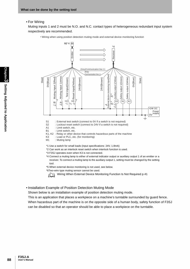
88
Chapter3
Setting Adjusted to A
pplication
F3SJ-AUser’s Manual
What can be done by the setting tool
• For WiringMuting inputs 1 and 2 must be N.O. and N.C. contact types of heterogeneous redundant input systemrespectively are recommended.
• Installation Example of Position Detection Muting ModeShown below is an installation example of position detection muting mode.This is an application that places a workpiece on a machine’s turntable surrounded by guard fence.When hazardous part of the machine is on the opposite side of a human body, safety function of F3SJcan be disabled so that an operator should be able to place a workpiece on the turntable.
K1
K2
S1
*1 *2*1
S2A1B1
M1*4
*3*4
K1 K2K3
+24V DC
0V
0V
(Blu
e)
0V
(Blu
e)
Powersupply
Em
itte
r
Re
ce
ive
r
(Grey)Communication line (+)
(Pink)
Communication line (-)
Shi
eld
Shi
eld
Te
st
inp
ut(
Gre
en
)
Re
se
t in
pu
t(Y
ello
w)
24
V(B
row
n)
24
V(B
row
n)
Ext
ern
al d
evi
ce m
on
itorin
g in
pu
t(R
ed
)
Auxi
liary
outp
ut 1(Y
ello
w)
Sa
fety
ou
tpu
t 1
(Gre
en
)
Sa
fety
ou
tpu
t 2
(Wh
ite
)
Mu
tin
g in
pu
t 1
(White)
Mu
tin
g in
pu
t 2
(Re
d)
Wiring when using position detection muting mode and external device monitoring function
S1
S2
A1
B1
K1, K2
K3
M1
: External test switch (connect to 0V if a switch is not required)
: Lockout reset switch (connect to 24V if a switch is not required)
: Limit switch, etc.
: Limit switch, etc.
: Relay or other device that controls hazardous parts of the machine
: Load or PLC, etc. (for monitoring)
: Muting lamp
*4
*566 **
*1 Use a switch for small loads (input specifications: 24V, 1.8mA)*2 Can work as an interlock reset switch when interlock function is used.*3 F3SJ operates even when K3 is not connected. *4 Connect a muting lamp to either of external indicator output or auxiliary output 1 of an emitter or a
receiver. To connect a muting lamp to the auxiliary output 1, setting must be changed by the setting tool.
*5 When external device monitoring is not used, see below. *6Two-wire type muting sensor cannot be used.
Wiring When External Device Monitoring Function Is Not Required p.41

89F3SJ-A
User’s Manual
Chapter3
Setting Adjusted to A
pplicationWhat can be done by the setting tool
E
1, Hazardous part of the machine is on the same side of a human body
The limit switch 1 of N.O contact is open and the muting input 1 is OFF, and the limit switch 2 of N.Ccontact is short-circuited and the muting input 2 is ON, and safety function of F3SJ is being enabled.
2, Hazardous part of the machine is on the opposite side of a human body
Rotation of a robot arm sets the muting input 1 from OFF to ON. Safety function of F3SJ is enabled.
When the muting input 1 turns from OFF to ON and when the muting input 2 is turned from ON to OFFwithin T1max [s] before or after the muting input 1's turning ON, safety function of F3SJ is disabled.(Safety output is kept ON even if F3SJ is blocked)
Under normal operation
Guard fenceF3SJ
24V
Worktable
Robot arm
table
OFF: To muting input 1
ON: To muting input 2
Limit switch1
(N.O. Contact)Limit switch 2
(N.C. Contact)
F3SJ
Under normal operation
OFF -> ON: To muting input 1
ON: To muting input 2
Limit switch1
(N.O. Contact)Limit switch 2
(N.C. Contact)
Guard fence
24V
Guard fence
Limit switch1
(N.O. Contact)Limit switch 2
(N.C. Contact)
During muting
ON: To muting input 1
ON -> OFF: To muting input 2
Input time difference between muting inputs 1 and 2
must be T1max or less
(initial setting is 3s)
F3SJ
24V
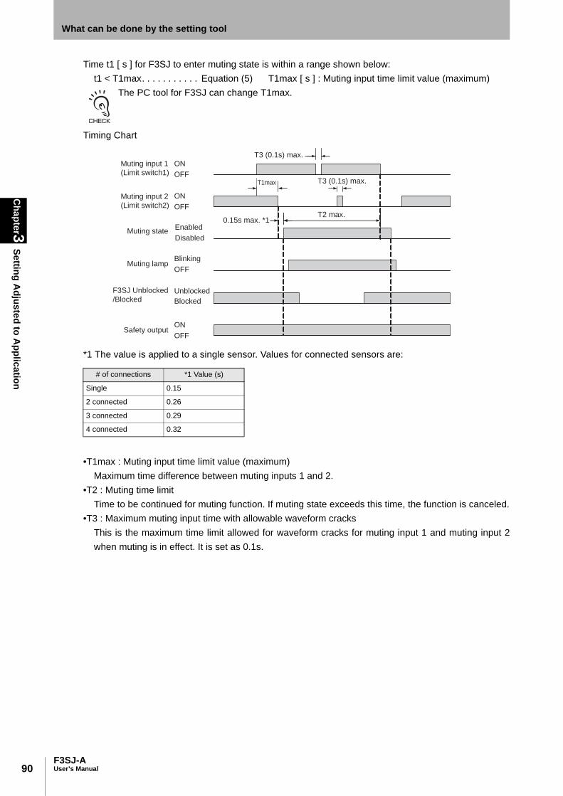
90
Chapter3
Setting Adjusted to A
pplication
F3SJ-AUser’s Manual
What can be done by the setting tool
Time t1 [ s ] for F3SJ to enter muting state is within a range shown below:t1 < T1max. . . . . . . . . . . Equation (5) T1max [ s ] : Muting input time limit value (maximum)
The PC tool for F3SJ can change T1max.
Timing Chart
*1 The value is applied to a single sensor. Values for connected sensors are:
•T1max : Muting input time limit value (maximum)Maximum time difference between muting inputs 1 and 2.
•T2 : Muting time limitTime to be continued for muting function. If muting state exceeds this time, the function is canceled.
•T3 : Maximum muting input time with allowable waveform cracksThis is the maximum time limit allowed for waveform cracks for muting input 1 and muting input 2when muting is in effect. It is set as 0.1s.
# of connections *1 Value (s)
Single 0.15
2 connected 0.26
3 connected 0.29
4 connected 0.32
Muting input 1
(Limit switch1)
ON
OFF
Muting input 2
(Limit switch2)
F3SJ Unblocked
/BlockedUnblocked
Blocked
Safety output
ON
OFF
ON
OFF
Enabled
Disabled
Muting lampBlinking
OFF
T1max
Muting state
T2 max.0.15s max. *1
T3 (0.1s) max.
T3 (0.1s) max.

91F3SJ-A
User’s Manual
Chapter3
Setting Adjusted to A
pplicationWhat can be done by the setting tool
E
Setting ChangeSetting items vary according to the mode. Muting zone setting: Configure for each CH in case of a series connection.Other than the above: Configure in a bulk in case of a series connection. (to be written into the primarysensor only)
Standard muting mode
Exit only muting mode (PC tool for F3SJ only)
Position detection muting mode (PC tool for F3SJ only)
If muting function is enabled, either output mode of external indicator output 1, 2, or auxiliary output 1 must beconfigured as shown below.
- Muting information- Muting/override information
Limitation for Combination with Other FunctionsYou can use this function in combination with fixed blanking, floating blanking, and warning zonefunctions at the same time with the PC tool for F3SJ. Note that there is a limitation for setting withzones.The setting console can be combined with fixed blanking function.For details, see Setting Zone Adjacent Conditions p.92 .
Setting Zone Adjacent Conditions p.92
Function Initial Setting Available Setup Item Setting Console PC Tool For F3SJ
Muting Zone Setting All beams 1 to all beams
T1min: Muting input time limit (minimum value)
0.03s 0.03s, 0.1s to 3.9s (by 0.1s)–
T1max: Muting input time limit (maximum value)
3s 0.2s to 4s (by 0.1s)–
T2: Muting time limit 60s 1s to 600s (by 1s) or infinite
Function Initial Setting Available Setup Item Setting Console PC Tool For F3SJ
Muting Zone Setting All beams 1 to all beams –
T1min: Muting input time limit (minimum value)
0.03s 0.03s, 0.1s to 3.9s (by 0.1s)–
T1max: Muting input time limit (maximum value)
3s 0.2s to 4s (by 0.1s)–
T2: Muting time limit 60s 1s to 600s (by 1s) or infinite –
T5: Exit only muting delay time 4s 0.1s to 4s (by 0.1s) –
Function Initial Setting Available Setup Item Setting Console PC Tool For F3SJ
Muting Zone Setting All beams 1 to all beams –
T1min: Muting input time limit (maximum value)
3s 0.1s to 4s (by 0.1s)–
T2: Muting time limit 60s 1s to 600s (by 1s) or infinite –

92
Chapter3
Setting Adjusted to A
pplication
F3SJ-AUser’s Manual
What can be done by the setting tool
Override Function Overview
Configures override function.
The override function disables safety functions of the device. You must ensure safety using other measures during this function is enabled.
All external indicators that indicate state of override function must be installed where workers can see them from all the operating positions.
Install the switch that activates the override and that uses hold-to-run device, such as spring-return key switch, in a location that provides a clear view of the entire hazardous zone and where it cannot be activated from within the hazardous zone. Make sure that nobody is in the hazardous zone before activating the override function.
Override time must be properly configured for its application by a sufficiently trained and qualified person.
Example•To extend override continuance time
Functional Description• Override Function
The setting tool can disable override function. (Enabled for factory shipment)Override Function p.52
• Override Time LimitOverride continuance time at the function’s activation can be changed. (60s for factory shipment)
Setting ChangeConfigure in a bulk in case of a series connection. (to be written into the primary sensor only)
If override function is enabled, we recommend either output mode of external indicator output 1, 2, or auxiliary output1 should be configured as shown below.
- Override information- Muting/override information
Setting Zone Adjacent ConditionsIf any two functions of muting, fixed blanking, floating blanking, or warning zone functions are used atthe same time, the setting zones have limitations.This section describes the limitations for following points:
1. Zone adjacent condition: If zones for multiple functions are configured adjacently2. Zone overlap condition: If zones for multiple functions are configured as overlapped
Function Initial Setting Available Setup Item Setting Console PC Tool For F3SJ
Override Function Enabled Enable/disable –
Override Time Limit 60s 1s to 600s (by 1s)
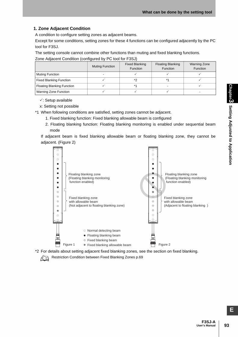
93F3SJ-A
User’s Manual
Chapter3
Setting Adjusted to A
pplicationWhat can be done by the setting tool
E
1. Zone Adjacent ConditionA condition to configure setting zones as adjacent beams.Except for some conditions, setting zones for these 4 functions can be configured adjacently by the PCtool for F3SJ.The setting console cannot combine other functions than muting and fixed blanking functions. Zone Adjacent Condition (configured by PC tool for F3SJ)
: Setup availablex: Setting not possible
*1 When following conditions are satisfied, setting zones cannot be adjacent.1. Fixed blanking function: Fixed blanking allowable beam is configured2. Floating blanking function: Floating blanking monitoring is enabled under sequential beam
modeIf adjacent beam is fixed blanking allowable beam or floating blanking zone, they cannot beadjacent. (Figure 2)
*2 For details about setting adjacent fixed blanking zones, see the section on fixed blanking. Restriction Condition between Fixed Blanking Zones p.69
Muting FunctionFixed Blanking
FunctionFloating Blanking
FunctionWarning Zone
Function
Muting Function -
Fixed Blanking Function *2 *1
Floating Blanking Function *1 -
Warning Zone Function -
Floating blanking zone
(Floating blanking monitoring
function enabled)
Floating blanking zone
(Floating blanking monitoring
function enabled)
Fixed blanking zone
with allowable beam
(Not adjacent to floating blanking zone)
Fixed blanking zone
with allowable beam
(Adjacent to floating blanking )
Figure 1 Figure 2
Normal detecting beam
Floating blanking beam
Fixed blanking beam
Fixed blanking allowable beam

94
Chapter3
Setting Adjusted to A
pplication
F3SJ-AUser’s Manual
What can be done by the setting tool
2. Zone Overlap ConditionA condition to configure setting zones as overlapped.Except for combination of muting zone and fixed blanking zone (figure 3), setting zones of these 4functions cannot be configured as overlapped. (Figure 4)Zone overlap condition
: Setup availablex: Setting not possible
Even if a muting zone and a fixed blanking zone are configured as overlapped, fixed blanking monitoring function iseffective. Thus a fixed blanking beam receives light under muting, operation is based on setting of the monitoringfunction.
Muting FunctionFixed Blanking
FunctionFloating Blanking
FunctionWarning Zone
Function
Muting Function - x x
Fixed Blanking Function x x x
Floating Blanking Function x x - x
Warning Zone Function x x x -
Muting zone
Fixed blanking zone
Floating blanking zone
Fixed blanking zone
Muting zone
Alarm zone
Figure 4Figure 3
95F3SJ-A
User’s Manual
Chapter3
Indicator/Input & O
utput SettingWhat can be done by the setting tool
E
Indicator/Input & Output Setting
Auxiliary Output (Non-Safety Output) Overview
Auxiliary outputs 1 and 2 can be changed.
Do not use auxiliary output or external indicator output for safety applications. Failure of these outputs may result in serious injury.
Example•To assign lockout output or warning zone output to auxiliary output•To blink an external indicator connected to auxiliary output
Functional Description• Auxiliary Output (Non-Safety Output)
Chapter 2 Basic System Auxiliary Output (Non-Safety Output) p.32
• Output Operation ModeSelect output detail from auxiliary output.
• Reverse Output ModeReverses auxiliary output logic.
• Lighting-Up PatternConfigures lighting-up/blinking pattern when connecting an indicator to auxiliary output.
• Auxiliary Output Diagnosis FunctionEnabling auxiliary output diagnosis allows breakage*1 and short circuit detection*2 of auxiliary output1.Use incandescent lamp if you want to use an indicator connected to auxiliary output 1 and enable thediagnosis function.
*1 Breakage detection: When there is breakage of auxiliary output 1, F3SJ is transitioned to lockout.*2 Short circuit detection:When there is short-circuit of auxiliary output 1, F3SJ is transitioned tolockout.
- If output operation mode and reverse output mode are used for other than initial setting, do not short-circuit byauxiliary output and external device monitoring input. When external device monitoring function is not used, disablethe external device monitoring function.
External Device Monitoring Function p.102
- For auxiliary output 1 and 2, load current must be 300mA or less and 50mA or less respectively.

96
Chapter3
Indicator/Input & O
utput Setting
F3SJ-AUser’s Manual
What can be done by the setting tool
Setting Change• Auxiliary Output 1
Configure in a bulk in case of a series connection. (to be written into the primary sensor only)
• Auxiliary Output 2
If F3SJ is used for a muting system, auxiliary output 2 cannot be used because it is used as muting input 2.Muting System Wiring Diagrams p.40
Output Operation Mode (when assigned to auxiliary output and external indicatoroutput)
Function Initial Setting Available Setup Item Setting Console PC Tool For F3SJ
Output Operation Mode Safety Output Information
See Output Operation Mode
Reverse Output Mode Enabled Enable/disable
Lighting-Up Pattern ON On/Blink[0.5s]/Blink[1.0s]/Blink[2.0s]
Auxiliary Output Diagnosis Function
Disabled Enable/disable
Function Initial Setting Available Setup Item Setting Console PC Tool For F3SJ
Output Operation Mode Power-On Time Information(30,000 hours)
See table below
Reverse Output Mode Disabled Enable/disable
Output Operation ModeOperational Description
(Output turns ON under following condition)Setting
ConsolePC Tool Forpc tool for F3SJ
Safety Output Information When safety output is ON
Light Level Diagnosis Information *1 When F3SJ is under ON state and light intensity is within a range from 100 to 130% of ON-threshold for 10 seconds or longer.
Error/Lockout Information Under error/lockout state
Muting/Override Information Under either muting or override state
Blanking/Warning Zone Information *2 When fixed blanking/floating blanking functions and warning zone function are enabled
Designated Beam Output Information *3 When designated beam is interrupted –
Power-On Time Information When power-on time exceeds power-on time threshold
Warning Zone Information *4 When a warning zone is interrupted
Test input ON information When test input is turned ON
Blanking Beam Incidence Information *5 When fixed blanking or floating blanking beams are incident
Interlock Information Under interlock state
Muting Error Information Under muting error state
Excess Load Switch Frequency Information
When the load switching frequency exceeds its threshold.
Information Trigger Information Under either interlock, lockout, or muting error –
Connected Sensor Individual Output (1CH)
When safety output of 1CH under series connection is ON (auxiliary output 1 only)
(auxiliary output 1 only)
Connected Sensor Individual Output (2CH)
When safety output of 2CH under series connection is ON (auxiliary output 1 only)
(auxiliary output 1 only)
Connected Sensor Individual Output (3CH)
When safety output of 3CH under series connection is ON (auxiliary output 1 only)
(auxiliary output 1 only)
Connected Sensor Individual Output(4CH)
When safety output of 4CH under series connection is ON (auxiliary output 1 only)
(auxiliary output 1 only)

97F3SJ-A
User’s Manual
Chapter3
Indicator/Input & O
utput SettingWhat can be done by the setting tool
E
*1 Beams for which output does not turn ON when interrupted, such as fixed or floating blanking beams,are excluded. Evaluation is not performed during overriding as well.
*2 Fixed blanking or floating blanking beam setting is required.*3 Designated beam setting is required.*4 Warning Zone beam setting is required. *5 ON state is kept until the sensor is reset by power cycle or the reset input.
- Fixed Blanking Function p.66 - Floating Blanking Function p.70 - Designated Beam Output Function p.97 - Warning Zone Function p.78 If "designated beam output information" is assigned for output operation mode of auxiliary outputs 1 or 2 or externalindicator outputs 1 or 2, these cannot be assigned to other output operation.
Designated Beam Output Function Overview
Incidence/interruption information of a given beam can be output. This function is for the PC tool forF3SJ only.
Example•To turn an external indicator ON when a specified beam of F3SJ is interrupted•To provide an auxiliary output when a specified beam of F3SJ is receiving light
Functional Description• Designated Beam Output Function
If one or more specified beams are interrupted or receiving light, the state of interruption/reception canbe provided as an auxiliary output or an external indicator output operation.Note that a designated beam output must be assigned to an output operation mode.
- Auxiliary Output (Non-Safety Output) p.95 - External Indicator Output (Non-Safety Output) p.99
• Designated Beam Zone SettingUse this setting to set the beams to use as designated beams. With an interrupting object in the appropriate position, it is possible to perform teaching and designatebeams manually.
• Designated Beam Incidence StateSpecifies output status of a designated beam whether it is receiving light or interrupted.ON when interrupted: Output turns ON if one or more beams are interrupted.ON when receiving: Output turns ON if one or more beams are receiving light.

98
Chapter3
Indicator/Input & O
utput Setting
F3SJ-AUser’s Manual
What can be done by the setting tool
Setting ChangeConfigure for each CH in case of a series connection.
- If you need output of designated beam’s incidence/interruption status, set output mode of auxiliary output or externalindicator output to designated beam information.
- Auxiliary Output (Non-Safety Output) p.95 - External Indicator Output (Non-Safety Output) p.99
- Combination of reverse output mode of external indicator output or auxiliary output enables setting of designatedbeam output as shown below.
• Operation ExampleDesignated beam incidence state: ON when interrupted
Function Initial Setting Available Setup Item Setting Console PC Tool For F3SJ
Designated Beam Zone Setting 0 Any beam –
Designated Beam Incidence State
ON when Interrupted
ON when Interrupted/On when receiving
–
Designated Beam Incidence State
Reverse Output Mode: Disabled Reverse Output Mode: Enabled
ON when Interrupted ON if 1 or more beams are interrupted(OFF when all beams are receiving light)
OFF even if 1 or more beams are interrupted(ON when all beams are receiving light)
ON when Receiving Light ON if 1 or more beams are receiving light(OFF when all beams are interrupted)
OFF if 1 or more beams are receiving light(ON when all beams are interrupted)
Safety output ON Safety output OFF Safety output OFF
Specified beam output OFF Specified beam output OFFSpecified beam output ON
Figure 1 Figure 2 Figure 3
Specified
beam
Specified
beam
F3SJ Unblocked/Blocked
F3SJ Unblocked/Blocked
(Specified beam)
Unblocked
Blocked
(Other than specified beam)
Specified beam outputON
OFF
Unblocked
Blocked
Safety outputON
OFF
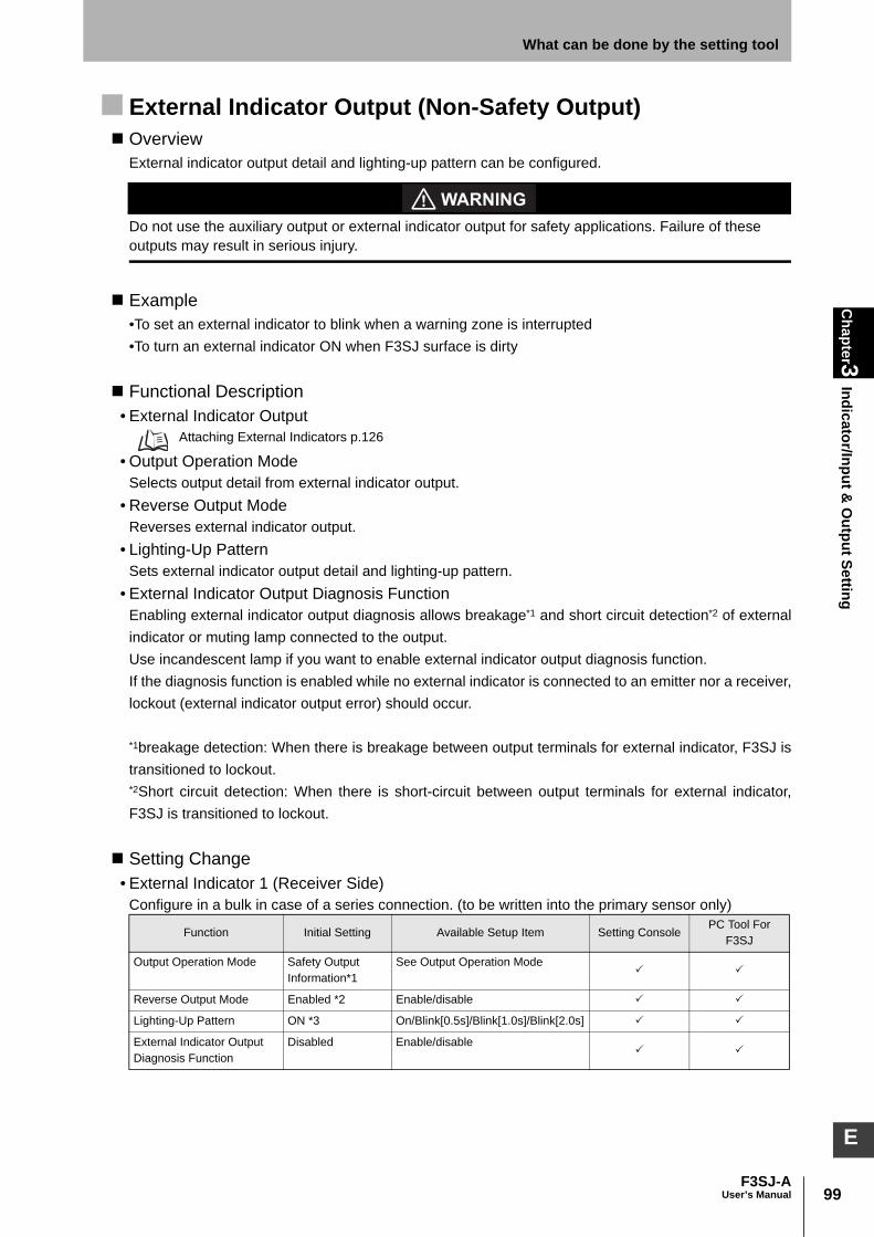
99F3SJ-A
User’s Manual
Chapter3
Indicator/Input & O
utput SettingWhat can be done by the setting tool
E
External Indicator Output (Non-Safety Output) Overview
External indicator output detail and lighting-up pattern can be configured.
Do not use the auxiliary output or external indicator output for safety applications. Failure of these outputs may result in serious injury.
Example•To set an external indicator to blink when a warning zone is interrupted•To turn an external indicator ON when F3SJ surface is dirty
Functional Description• External Indicator Output
Attaching External Indicators p.126
• Output Operation ModeSelects output detail from external indicator output.
• Reverse Output ModeReverses external indicator output.
• Lighting-Up PatternSets external indicator output detail and lighting-up pattern.
• External Indicator Output Diagnosis FunctionEnabling external indicator output diagnosis allows breakage*1 and short circuit detection*2 of externalindicator or muting lamp connected to the output.Use incandescent lamp if you want to enable external indicator output diagnosis function. If the diagnosis function is enabled while no external indicator is connected to an emitter nor a receiver,lockout (external indicator output error) should occur.
*1breakage detection: When there is breakage between output terminals for external indicator, F3SJ istransitioned to lockout.*2Short circuit detection: When there is short-circuit between output terminals for external indicator,F3SJ is transitioned to lockout.
Setting Change• External Indicator 1 (Receiver Side)
Configure in a bulk in case of a series connection. (to be written into the primary sensor only)
Function Initial Setting Available Setup Item Setting ConsolePC Tool For
F3SJ
Output Operation Mode Safety Output Information*1
See Output Operation Mode
Reverse Output Mode Enabled *2 Enable/disable
Lighting-Up Pattern ON *3 On/Blink[0.5s]/Blink[1.0s]/Blink[2.0s]
External Indicator Output Diagnosis Function
Disabled Enable/disable

100
Chapter3
Indicator/Input & O
utput Setting
F3SJ-AUser’s Manual
What can be done by the setting tool
• External Indicator 2 (Emitter Side)
*1 For a muting system, muting override output is set.*2 For a muting system, it is configured as disabled.*3 For a muting system, it is configured as blinking [1.0s].
Output Operation ModeSee Chapter 3 Auxiliary Output (Non-Safety Output) p.95 Output Operation Mode.
Output Operation Mode p.96
Interlock Function Overview
Start and restart interlock functions can be configured.
Install the interlock reset switch in a location that provides a clear view of the entire hazardous zone and where it cannot be activated from within the hazardous zone.
Example•To operate a machine after power-on and inspection•To restart a machine after safety check when F3SJ was blocked and the machine stopped
Functional Description• Interlock Function
Chapter 2 Interlock Function p.29 • Start Interlock
With this setting, F3SJ enters interlock only when power is turned ON. Applying reset input can releaseinterlock state when no interrupting object exists in the detection zone. This can be used to operate amachine after power-on and inspection.
• Restart InterlockWith this setting, F3SJ enters interlock state only when the sensor is interrupted. Applying reset inputcan release interlock state when no interrupting object exists in the detection zone. If F3SJ is blocked,the machine can be restarted after safety is ensured.
• Interlock ResetFor basic system: Apply voltage of 9 to Vs (nominal 24V) for 250ms or longer to the reset input line,and set it open or apply 0 to 1.5V.For muting system: Open or apply voltage of 0 to 1.5V for 450ms or longer to the reset input line, andapply 9V to Vs (nominal 24V) again.
Function Initial Setting Available Setup Item Setting ConsolePC Tool For
F3SJ
Output Operation Mode Lockout Information *1
See Output Operation Mode
Reverse Output Mode Disabled *2 Enable/disable
Lighting-Up Pattern ON *3 On/Blink[0.5s]/Blink[1.0s]/Blink[2.0s]
External Indicator Output Diagnosis Function
Disabled Enable/disable
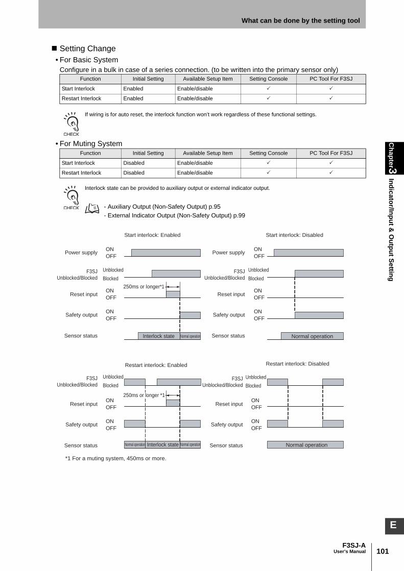
101F3SJ-A
User’s Manual
Chapter3
Indicator/Input & O
utput SettingWhat can be done by the setting tool
E
Setting Change• For Basic System
Configure in a bulk in case of a series connection. (to be written into the primary sensor only)
If wiring is for auto reset, the interlock function won’t work regardless of these functional settings.
• For Muting System
Interlock state can be provided to auxiliary output or external indicator output.
- Auxiliary Output (Non-Safety Output) p.95 - External Indicator Output (Non-Safety Output) p.99
Function Initial Setting Available Setup Item Setting Console PC Tool For F3SJ
Start Interlock Enabled Enable/disable
Restart Interlock Enabled Enable/disable
Function Initial Setting Available Setup Item Setting Console PC Tool For F3SJ
Start Interlock Disabled Enable/disable
Restart Interlock Disabled Enable/disable
Reset inputON
OFF
Safety outputON
OFF
250ms or longer*1
Sensor status Interlock state
Power supplyON
OFF
Normal operation
Start interlock: Enabled
Restart interlock: Enabled
Start interlock: Disabled
Restart interlock: Disabled
Normal operation
Normal operation
Normal operationNormal operation
Reset inputON
OFF
Safety outputON
OFF
Sensor status
Reset inputON
OFF
Safety outputON
OFF
Sensor status
Reset inputON
OFF
Safety outputON
OFF
F3SJ
Unblocked/Blocked
Sensor status
Power supplyON
OFF
Unblocked
Blocked
F3SJ
Unblocked/Blocked
Unblocked
Blocked
F3SJ
Unblocked/Blocked
Unblocked
Blocked
F3SJ
Unblocked/Blocked
Unblocked
Blocked
250ms or longer *1
*1 For a muting system, 450ms or more.
Interlock state
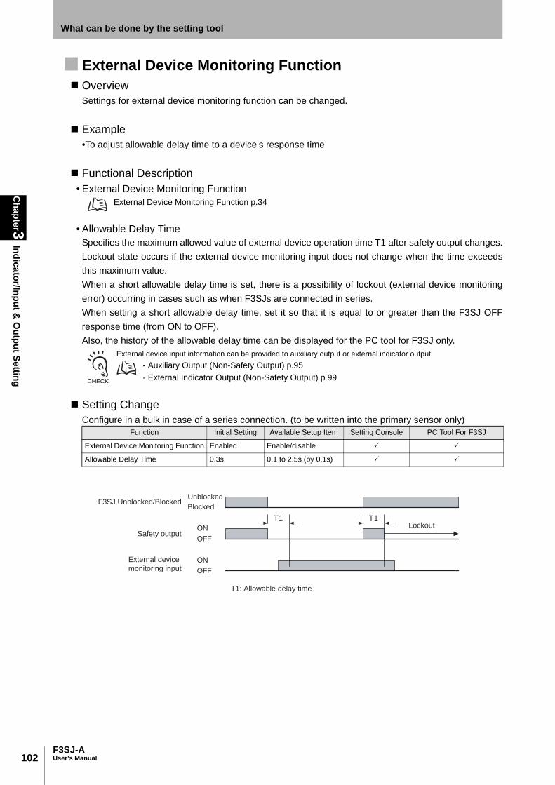
102
Chapter3
Indicator/Input & O
utput Setting
F3SJ-AUser’s Manual
What can be done by the setting tool
External Device Monitoring Function Overview
Settings for external device monitoring function can be changed.
Example•To adjust allowable delay time to a device’s response time
Functional Description• External Device Monitoring Function
External Device Monitoring Function p.34
• Allowable Delay TimeSpecifies the maximum allowed value of external device operation time T1 after safety output changes.Lockout state occurs if the external device monitoring input does not change when the time exceedsthis maximum value.When a short allowable delay time is set, there is a possibility of lockout (external device monitoringerror) occurring in cases such as when F3SJs are connected in series.When setting a short allowable delay time, set it so that it is equal to or greater than the F3SJ OFFresponse time (from ON to OFF).Also, the history of the allowable delay time can be displayed for the PC tool for F3SJ only.
External device input information can be provided to auxiliary output or external indicator output.- Auxiliary Output (Non-Safety Output) p.95 - External Indicator Output (Non-Safety Output) p.99
Setting ChangeConfigure in a bulk in case of a series connection. (to be written into the primary sensor only)
Function Initial Setting Available Setup Item Setting Console PC Tool For F3SJ
External Device Monitoring Function Enabled Enable/disable
Allowable Delay Time 0.3s 0.1 to 2.5s (by 0.1s)
Safety outputON
OFF
External device
monitoring inputON
OFF
F3SJ Unblocked/BlockedUnblocked
Blocked
LockoutT1 T1
T1: Allowable delay time
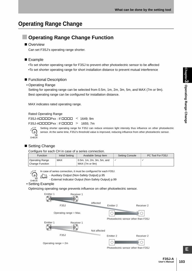
103F3SJ-A
User’s Manual
Chapter3
Operating R
ange ChangeWhat can be done by the setting tool
E
Operating Range Change
Operating Range Change Function Overview
Can set F3SJ’s operating range shorter.
Example•To set shorter operating range for F3SJ to prevent other photoelectric sensor to be affected•To set shorter operating range for short installation distance to prevent mutual interference
Functional Description• Operating Range
Setting for operating range can be selected from 0.5m, 1m, 2m, 3m, 5m, and MAX (7m or 9m).Best operating range can be configured for installation distance.
MAX indicates rated operating range.
Rated Operating RangeF3SJ-APxx : If 1649; 9mF3SJ-APxx : If 1655; 7m
Setting shorter operating range for F3SJ can reduce emission light intensity thus influence on other photoelectricsensor. At the same time, F3SJ’s threshold value is improved, reducing influence from other photoelectric sensor.
Setting ChangeConfigure for each CH in case of a series connection.
In case of series connection, it must be configured for each F3SJ.- Auxiliary Output (Non-Safety Output) p.95 - External Indicator Output (Non-Safety Output) p.99
• Setting ExampleOptimizing operating range prevents influence on other photoelectric sensor.
Function Initial Setting Available Setup Item Setting Console PC Tool For F3SJ
Operating Range Change Function
MAX 0.5m, 1m, 2m, 3m, 5m, and MAX (7m or 9m)
Emitter 1 Receiver 1
Emitter 2 Receiver 2
Operating range = Max.
Emitter 1
F3SJ
F3SJ
Receiver 1
Emitter 2 Receiver 2
Operating range = 2m
Affected
Not affected
Photoelectric sensor other than F3SJ
Photoelectric sensor other than F3SJ
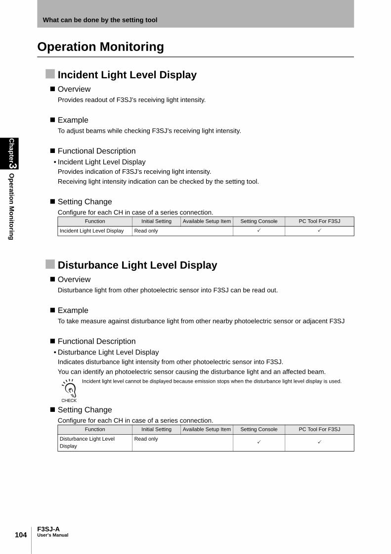
104
Chapter3
Operation M
onitoring
F3SJ-AUser’s Manual
What can be done by the setting tool
Operation Monitoring
Incident Light Level Display Overview
Provides readout of F3SJ’s receiving light intensity.
ExampleTo adjust beams while checking F3SJ’s receiving light intensity.
Functional Description• Incident Light Level Display
Provides indication of F3SJ’s receiving light intensity.Receiving light intensity indication can be checked by the setting tool.
Setting ChangeConfigure for each CH in case of a series connection.
Disturbance Light Level Display Overview
Disturbance light from other photoelectric sensor into F3SJ can be read out.
ExampleTo take measure against disturbance light from other nearby photoelectric sensor or adjacent F3SJ
Functional Description• Disturbance Light Level Display
Indicates disturbance light intensity from other photoelectric sensor into F3SJ.You can identify an photoelectric sensor causing the disturbance light and an affected beam.
Incident light level cannot be displayed because emission stops when the disturbance light level display is used.
Setting ChangeConfigure for each CH in case of a series connection.
Function Initial Setting Available Setup Item Setting Console PC Tool For F3SJ
Incident Light Level Display Read only
Function Initial Setting Available Setup Item Setting Console PC Tool For F3SJ
Disturbance Light Level Display
Read only

105F3SJ-A
User’s Manual
Chapter3
Operation M
onitoringWhat can be done by the setting tool
E
Status Information Display Overview
Provides readout of F3SJ’s I/O information and status. This function is for the PC tool for F3SJ only.
Functional DescriptionF3SJ’s I/O information and status can be read out by the PC tool for F3SJ.
Setting ChangeConfigure in a bulk in case of a series connection. (to be written into the primary sensor only)
Information available to read
*1 When the F3SJ is in maintenance status, the actual safety output does not turn ON even when theoutput status of the safety output is ON.
Function Initial Setting Available Setup Item Setting Console PC Tool For F3SJ
Status Monitor Read only –
F3SJ Status Description
Test Input Linked to test input
Reset Input Linked to reset input
Interlock Selection Input Linked to interlock selection input
Muting Input 1 Linked to muting input 1 (for a muting system)
Muting Input 2 Linked to muting input 2 (for a muting system)
Safety Output 1 *1 Linked to safety output 1
Safety Output 2 *1 Linked to safety output 2
Auxiliary Output 1 Linked to auxiliary output 1
Auxiliary Output 2 Linked to auxiliary output 2
External Indicator (Emitter) Linked to external indicator output 1
External Indicator (Receiver) Linked to external indicator output 2
Incident Light Level Indicator Indicates light intensity level indicator
Interlock state Displayed when in interlock
Source Voltage Indicates supplied source voltage
Muting state ON when muting
Muting error state ON when there is a muting error
Override state ON when in override
Blanking beam incidence state ON when blanking beam is incident
Light level diagnosis information When F3SJ is ON and the incident light level is 130% or less of the ON threshold value for 10 seconds or more

106
Chapter3
Maintenance Inform
ation
F3SJ-AUser’s Manual
What can be done by the setting tool
Maintenance Information
Error History Overview
Details of errors that occurred in the past are displayed.
Functional DescriptionThe PC tool for F3SJ can display the past 20 error codes, and the setting console can display the past10 error codes.The PC setting tool for F3SJ can record error codes as well as F3SJ's internaltemperature, which can be displayed too. For an explanation of the error codes, refer to thetroubleshooting section at the end of this manual.
Troubleshooting p.186
Monitor ItemsConfigure for each CH in case of a series connection.
- When the setting tool is connected while power is being supplied to the F3SJ, the F3SJ enters communication errorlockout. When checking errors in the error log, ignore the error that occurred most recently and check the second orearlier errors.
- When an error occurred, a supply voltage error may be recorded in addition to the original error code if supply voltageis out of specification range.
Power-on Time Overview
The power-on time of the F3SJ is displayed.
Functional DescriptionData related to the power-on time of the F3SJ is recorded in the F3SJ main unit every 15 minutes. Therecord is made when in normal operation or during lockout. By knowing the power-on time, you canbetter understand when to schedule F3SJ maintenance.
• Power-on timeThis is the current power-on time since the power-on time was last reset. If the power-on time hasnever been reset, this value is the same as the accumulated power-on time. This value can bechecked for an emitter and a receiver separately.
• Power-on time threshold valueWhen the power-on time exceeds this value, output can be performed to the auxiliary output or theexternal indicator output. Note that the power-on time information must be assigned to an output mode. (In the initial settings, it is assigned to auxiliary output 2.)
- Auxiliary Output (Non-Safety Output) p.95 - External Indicator Output (Non-Safety Output) p.99
Function Setting Console PC Tool For F3SJ
Error history

107F3SJ-A
User’s Manual
Chapter3
Maintenance Inform
ationWhat can be done by the setting tool
E
• Accumulated power-on timeThis value represents the cumulative power-on time, from the time that the power was first supplieduntil the present. It is not possible to reset this value using the power-on time reset function.
• Power-on time resetThis function can reset the power-on time of the F3SJ to 0. In the case of series connection, thepower-on time can be reset for each F3SJ CH.
Monitor ItemsConfigure or display for each CH in case of a series connection.
Function Initial Setting Available Setup Item Setting Console PC Tool For F3SJ
Power-on time Read out only
Power-on time threshold value 30,000 hours Setting Console:100 to 999,900 hours (by 100 hours)PC Tool for F3SJ:100 to 1,000,000 hours (by 100 hours)
Accumulated power-on time Read out only
Power-on time reset – Reset

108
Chapter3
Maintenance Inform
ation
F3SJ-AUser’s Manual
What can be done by the setting tool
Load Switching Frequency Overview
This value represents load switching frequency connected to F3SJ.
Functional DescriptionThe number of times the F3SJ safety output has switched from ON to OFF is recorded in the F3SJmain unit every 15 minutes. The record is made when in normal operation or during lockout. Bymonitoring the number of times the safety output has switched from ON to OFF, you can understandthe number of responses that have been made by the relays and contactors connected to the F3SJ.
• Load switching frequencyThis value represents load switching frequency connected to F3SJ. In the case of series connection,load switching frequency can be displayed for each F3SJ CH.
• Load switching frequency threshold value When load switching frequency exceeds this value, output can be performed to the auxiliary outputor the external indicator output.Note that excess load switching frequency information must be assigned to an output operationmode.
- Auxiliary Output (Non-Safety Output) p.95 - External Indicator Output (Non-Safety Output) p.99
• Accumulated load switching frequencyThis value indicates the cumulative value for load switching frequency, from the time that power wasfirst supplied to the F3SJ until the present.It is not possible to reset this value using load switching frequency reset function.
• Load switching frequency reset This function resets load switching frequency recorded in the F3SJ. Use this reset functionwhenever you install or replace relays or contactors.
Monitor ItemsConfigure in a bulk or display in case of a series connection. (to be written into the primary sensor only)
Function Initial Setting Available Setup Item Setting Console PC Tool For F3SJ
Load switching frequency Read out only –
Load switching frequency threshold value
100,000 times 1,000 to 4,000,000 times (by 1,000 unit)
–
Accumulated load switching frequency
Read out only
Load switching frequency reset
– Reset

109F3SJ-A
User’s Manual
Chapter3
Setting Recovery
What can be done by the setting tool
E
Setting Recovery
Setting Recovery Function
A sufficiently trained and qualified person must perform setting recovery. Incorrect setting may cause a person to go undetected, resulting in serious injury.
To reset the configuration to previous one, safety distance may get longer. Always verify recalculation of safety distance and intended operation of F3SJ based on the change.
OverviewResets F3SJ’s settings to the factory shipment values or previous setting values.
ExampleTo reset the configuration because the settings were forgotten
Functional Description• Setting Recovery Function
By performing the setting recovery function, the setting console can be used to restore the F3SJ'sconfiguration to the factory settings. With the PC tool for F3SJ, the factory settings or the previoussettings (before the most recent change) can be restored.
Setting ChangeFunction Initial Setting Available Setup Item Setting Console PC Tool For F3SJ
Setting Recovery Function
–Factory Shipment Setting/Previous Setting
(Factory shipment setting only)

110
Chapter3
Other
F3SJ-AUser’s Manual
What can be done by the setting tool
Other
Safety Distance Calculation Function Overview
The safety distance specified by the international standard ISO13855-2002 (European standardEN999) is calculated.
Functional DescriptionThis function displays the safety distance based on the international standard ISO13855-2002(European standard EN999), according to the conditions that are input. This function is available onlyfor the PC tool for F3SJ.
Monitor Items
Connection Cable Length Calculation Function Overview
This function displays the connection cable's extendable length, which varies according to the F3SJconfiguration.
Functional DescriptionThe function displays the extendable length of the cable (excluding the length of cables between seriesconnections), according to the conditions that are input. For series connections, the maximumextendable length is 15 meters. This function is available only for the PC tool for F3SJ.
Monitor Items
Power Cable Length p.22
Rated Response Time Check Overview
The rated response time of the F3SJ is displayed.
Functional DescriptionThis function displays the OFF response time (from ON to OFF) and the ON response time (from OFFto ON) by connecting the F3SJ whose response time you want to check. If the F3SJ are in a seriesconnection, the response time for all F3SJ connected in series is shown.
Function Setting Console PC Tool For F3SJ
Safety distance calculation function –
Function Setting Console PC Tool For F3SJ
Connection cable extension calculation function –
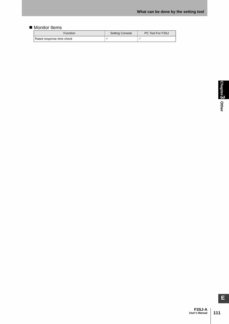
111F3SJ-A
User’s Manual
Chapter3
Other
What can be done by the setting tool
E
Monitor ItemsFunction Setting Console PC Tool For F3SJ
Rated response time check

112
Chapter3
Other
F3SJ-AUser’s Manual
What can be done by the setting tool

Chapter4
Wiring/Installation
113F3SJ-A
User’s Manual
E
Chapter4 Wiring/Installation
Installation Conditions 114
Detection Zone and Approach 114Safety Distance 115Distance from Reflective Surfaces 118Mutual Interference Prevention 119
Series Connection 122
Connection Procedure 124Attaching External Indicators 126
Connection Procedure 126Output Operation 127Setting Change by the Setting Tool 127
Dimensions 128
When Using Standard Mounting Brackets 128When Using Optional Mounting Brackets 131When Using Spatter Protection Covers 148Setting Tool 149Mounting a Protect Bar 150Mounting an Environment-Resistant Case 152
Mounting 154
Top/Bottom Mounting Brackets 154Intermediate Mounting Brackets 154Mounting Procedure 155Adjustment Procedure 158
Wiring 159
Wiring Precautions 159Power Supply Unit 160Wiring Procedure 161
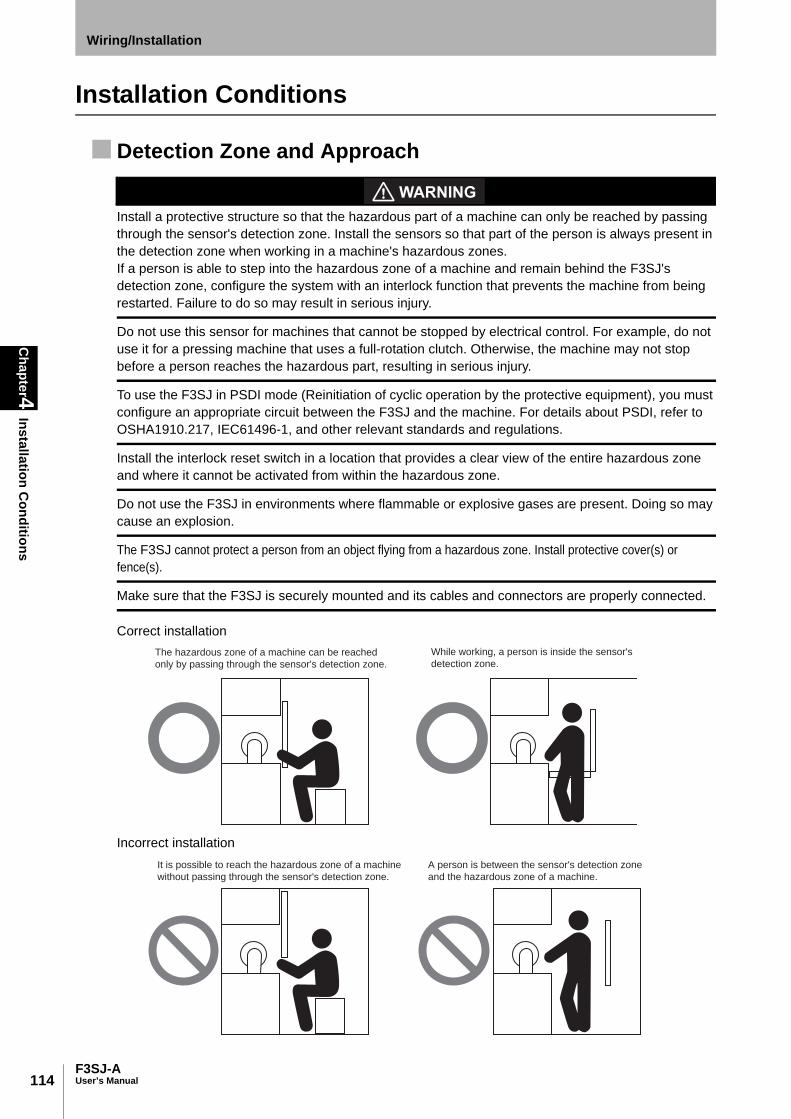
114
Chapter4
Installation Conditions
F3SJ-AUser’s Manual
Wiring/Installation
Installation Conditions
Detection Zone and Approach
Install a protective structure so that the hazardous part of a machine can only be reached by passing through the sensor's detection zone. Install the sensors so that part of the person is always present in the detection zone when working in a machine's hazardous zones. If a person is able to step into the hazardous zone of a machine and remain behind the F3SJ's detection zone, configure the system with an interlock function that prevents the machine from being restarted. Failure to do so may result in serious injury.
Do not use this sensor for machines that cannot be stopped by electrical control. For example, do not use it for a pressing machine that uses a full-rotation clutch. Otherwise, the machine may not stop before a person reaches the hazardous part, resulting in serious injury.
To use the F3SJ in PSDI mode (Reinitiation of cyclic operation by the protective equipment), you must configure an appropriate circuit between the F3SJ and the machine. For details about PSDI, refer to OSHA1910.217, IEC61496-1, and other relevant standards and regulations.
Install the interlock reset switch in a location that provides a clear view of the entire hazardous zone and where it cannot be activated from within the hazardous zone.
Do not use the F3SJ in environments where flammable or explosive gases are present. Doing so may cause an explosion.
The F3SJ cannot protect a person from an object flying from a hazardous zone. Install protective cover(s) or fence(s).
Make sure that the F3SJ is securely mounted and its cables and connectors are properly connected.
Correct installation
Incorrect installation
The hazardous zone of a machine can be reached
only by passing through the sensor's detection zone.
While working, a person is inside the sensor's
detection zone.
It is possible to reach the hazardous zone of a machine
without passing through the sensor's detection zone.
A person is between the sensor's detection zone
and the hazardous zone of a machine.

115F3SJ-A
User’s Manual
Chapter4
Installation Conditions
Wiring/Installation
E
Safety DistanceThe safety distance is the distance that must be set between the F3SJ and a machine's hazardous partto stop the hazardous part before a person or object reaches it. The safety distance varies according tothe standards of each country and the individual specifications of each machine. Always refer to therelevant standards.
Make sure to secure the safety distance (S) between the F3SJ and the hazardous part. Otherwise, the machine may not stop before a person reaches the hazardous part, resulting in serious injury.
The response time of a machine is the time period from when the machine receives a stop signal to when the machine'shazardous part stops. Measure the response time on the actual system. Also, periodically check that the response timeof the machine has not changed.
How to calculate the safety distance specified by International Standard ISO 13855-2002 (European standard EN999) (Reference) If a person approaches the detection zone of the F3SJ perpendicularly S = K x T + C . . . Formula (1)• S: Safety distance• K: Approach speed to the detection zone• T: Total response time of the machine and F3SJ• C: Additional distance calculated by the detection capability
of the F3SJ
<System that has detection capability of 40mm or less>Use K = 2,000mm/s and C = 8 x (d - 14mm) in formula (1)for the calculation. S = 2,000mm/s x (Tm + Ts) + 8 x (d - 14mm)•S = Safety distance (mm)•Tm = Machine's response time (s)•Ts = Response time of the F3SJ from ON to OFF (s)•d = Detection capability of the F3SJ (mm)
[Calculation example]When Tm = 0.05s, Ts = 0.01s, and d = 14mm: S=2,000mm/s x (0.05s + 0.01s) + 8 x (14mm - 14mm) = 120mm . . . Formula (2)If the result < 100mm, use S = 100mm. If the result exceeds 500mm, use the following expression where K = 1,600mm/s. S=1,600mm/s x (Tm + Ts) + 8 x (d - 14mm) . . . Formula (3)
If the result of this formula (3) < 500mm, use S = 500mm.
<A system with larger detection capability than 40mm>Calculate by using Equation (1) with K = 1,600mm/s and C = 850mm:S = 1,600mm/s x (Tm + Ts) + 850 . . . Equation (4)•S = Safety distance (mm)
Hazard
Safety distance (S)
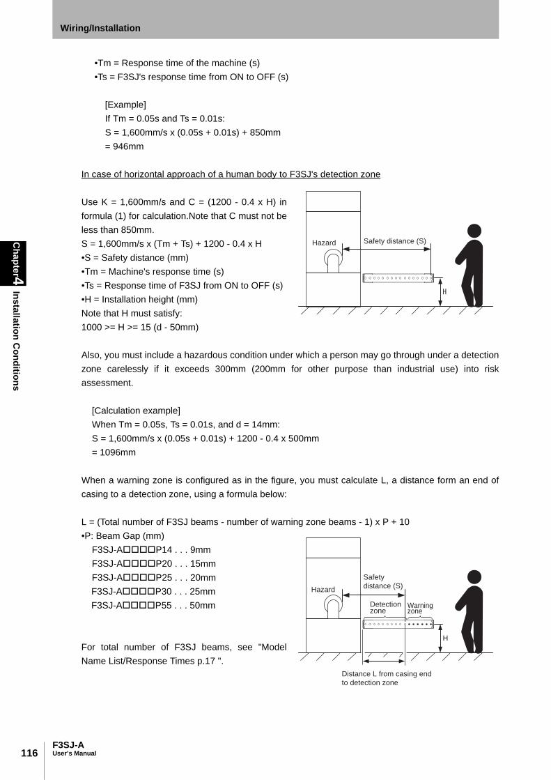
116
Chapter4
Installation Conditions
F3SJ-AUser’s Manual
Wiring/Installation
•Tm = Response time of the machine (s)•Ts = F3SJ's response time from ON to OFF (s)
[Example]If Tm = 0.05s and Ts = 0.01s:S = 1,600mm/s x (0.05s + 0.01s) + 850mm= 946mm
In case of horizontal approach of a human body to F3SJ's detection zone
Use K = 1,600mm/s and C = (1200 - 0.4 x H) informula (1) for calculation.Note that C must not beless than 850mm.S = 1,600mm/s x (Tm + Ts) + 1200 - 0.4 x H•S = Safety distance (mm)•Tm = Machine's response time (s)•Ts = Response time of F3SJ from ON to OFF (s)•H = Installation height (mm)Note that H must satisfy:1000 >= H >= 15 (d - 50mm)
Also, you must include a hazardous condition under which a person may go through under a detectionzone carelessly if it exceeds 300mm (200mm for other purpose than industrial use) into riskassessment.
[Calculation example]When Tm = 0.05s, Ts = 0.01s, and d = 14mm:S = 1,600mm/s x (0.05s + 0.01s) + 1200 - 0.4 x 500mm= 1096mm
When a warning zone is configured as in the figure, you must calculate L, a distance form an end ofcasing to a detection zone, using a formula below:
L = (Total number of F3SJ beams - number of warning zone beams - 1) x P + 10•P: Beam Gap (mm)
F3SJ-AP14 . . . 9mmF3SJ-AP20 . . . 15mmF3SJ-AP25 . . . 20mmF3SJ-AP30 . . . 25mmF3SJ-AP55 . . . 50mm
For total number of F3SJ beams, see "ModelName List/Response Times p.17 ".
Safety distance (S)Hazard
H
Safety
distance (S)Hazard
Distance L from casing end
to detection zone
Detection zone
Warning zone

117F3SJ-A
User’s Manual
Chapter4
Installation Conditions
Wiring/Installation
E
How to calculate the safety distance specified by American standard ANSI B11.19(reference)If a person approaches the detection zone of the F3SJ perpendicularly, calculate the safety distance asshown below. S = K x (Ts + Tc + Tr + Tbm) + Dpf•S: Safety distance•K: Approach speed to the detection zone (the value recommended by OSHA standard is 1,600mm/s)Approach speed K is not specified in the ANSI B.11.19 standard. To determine the value of K to apply,consider all factors, including the operator's physical ability. •Ts = Machine's stopping time (s) •Tr = Response time of the F3SJ from ON to OFF (s)•Tc = Machine control circuit's maximum response time required to activate its brake (s) •Tbm = Additional time (s)If a machine has a brake monitor, "Tbm= Brake monitor setting time - (Ts + Tc)". If it has no brakemonitor, we recommend using 20% or more of (Ts + Tc) as additional time. •Dpf = Additional distance According to ANSI's formula, Dpf is calculated as shown below: Dpf = 3.4 x (d - 7.0): Where d is the detection capability of the F3SJ (unit: mm)
[Calculation example]When K = 1,600mm/s, Ts + Tc = 0.06s, brake monitor setting time = 0.1s, Tr = 0.01s, and d = 14mm: Tbm = 0.1 - 0.06 = 0.04s Dpf = 3.4 x (14 - 7.0) = 23.8mm S = 1,600 x (0.06 + 0.01 + 0.04) + 23.8 = 199.8mm

118
Chapter4
Installation Conditions
F3SJ-AUser’s Manual
Wiring/Installation
Distance from Reflective Surfaces
Install the sensor system so that it is not affected by reflective surfaces. Failure to do so may hinder detection, resulting in serious injury.
Install the sensor system at distance D or further from highly reflective surfaces such as metallic walls,floors, ceilings, or workpieces, as shown below.
Distance between an emitter and a receiver (operating range L)
Allowable installation distance D
For 0.2 to 3m 0.13m
For 3m or more L/2 x tan5 ° = L x 0.044 (m)
L
D
D
L
D
5 5
Detection zone
Emitter Receiver
Reflective ceiling
Reflective floor
Emitter Receiver
Reflective surface
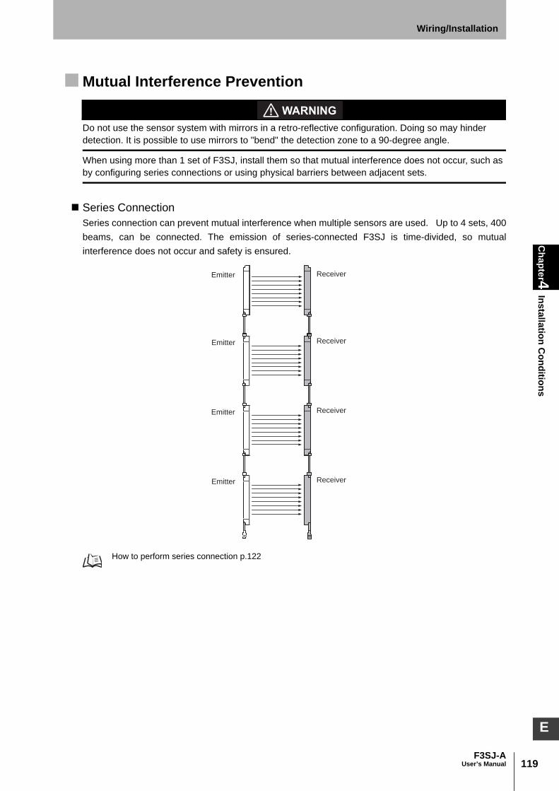
119F3SJ-A
User’s Manual
Chapter4
Installation Conditions
Wiring/Installation
E
Mutual Interference Prevention
Do not use the sensor system with mirrors in a retro-reflective configuration. Doing so may hinder detection. It is possible to use mirrors to "bend" the detection zone to a 90-degree angle.
When using more than 1 set of F3SJ, install them so that mutual interference does not occur, such as by configuring series connections or using physical barriers between adjacent sets.
Series ConnectionSeries connection can prevent mutual interference when multiple sensors are used. Up to 4 sets, 400beams, can be connected. The emission of series-connected F3SJ is time-divided, so mutualinterference does not occur and safety is ensured.
How to perform series connection p.122
Emitter Receiver
Emitter Receiver
Emitter Receiver
Emitter Receiver
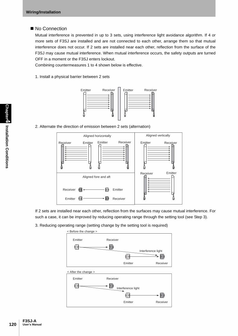
120
Chapter4
Installation Conditions
F3SJ-AUser’s Manual
Wiring/Installation
No ConnectionMutual interference is prevented in up to 3 sets, using interference light avoidance algorithm. If 4 ormore sets of F3SJ are installed and are not connected to each other, arrange them so that mutualinterference does not occur. If 2 sets are installed near each other, reflection from the surface of theF3SJ may cause mutual interference. When mutual interference occurs, the safety outputs are turnedOFF in a moment or the F3SJ enters lockout.Combining countermeasures 1 to 4 shown below is effective.
1. Install a physical barrier between 2 sets
2. Alternate the direction of emission between 2 sets (alternation)
If 2 sets are installed near each other, reflection from the surfaces may cause mutual interference. Forsuch a case, it can be improved by reducing operating range through the setting tool (see Step 3).
3. Reducing operating range (setting change by the setting tool is required)
Emitter ReceiverEmitter Receiver
Emitter Receiver Emitter Receiver Emitter Receiver
Emitter Receiver
Aligned horizontally
Aligned fore and aft
Aligned vertically
Receiver Emitter
Emitter Receiver
Emitter Receiver
Emitter Receiver
Interference light
< Before the change >
Emitter Receiver
Emitter Receiver
Interference light
< After the change >

121F3SJ-A
User’s Manual
Chapter4
Installation Conditions
Wiring/Installation
E
4. Keep sufficient distance between the F3SJs so that mutual interference does not occur
When using 4 or more sets that are not series-connected, the installations shown below may causemutual interference. When mutual interference occurs, the safety outputs are turned OFF in a momentor the F3SJ enters lockout.
Distance between emitter and receiver (operating range L)
Allowable installation distance D
For 0.2 to 3m 0.26m
For 3m or more L x tan5 ° = L x 0.088 (m)
DD
L
D
5
5 ReceiverEmitter Receiver
Emitter Receiver
Emitter Receiver
Emitter
Emitter Receiver Emitter Receiver
Emitter Receiver
ReceiverEmitter
Aligned horizontally
Aligned fore and aft
Emitter Receiver
Emitter Receiver
Aligned vertically
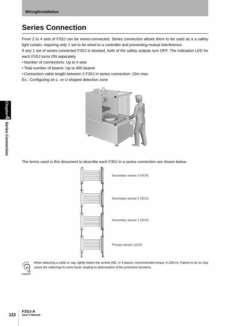
122
Chapter4
Series Connection
F3SJ-AUser’s Manual
Wiring/Installation
Series ConnectionFrom 2 to 4 sets of F3SJ can be series-connected. Series connection allows them to be used as a a safetylight curtain, requiring only 1 set to be wired to a controller and preventing mutual interference. If any 1 set of series-connected F3SJ is blocked, both of the safety outputs turn OFF. The indication LED foreach F3SJ turns ON separately. • Number of connections: Up to 4 sets • Total number of beams: Up to 400 beams• Connection cable length between 2 F3SJ in series connection: 15m max. Ex.: Configuring an L- or U-shaped detection zone
The terms used in this document to describe each F3SJ in a series connection are shown below.
When attaching a cable or cap, tightly fasten the screws (M2, in 4 places, recommended torque: 0.15Nm). Failure to do so maycause the cable/cap to come loose, leading to deterioration of the protective functions.
Secondary sensor 3 (4CH)
Secondary sensor 2 (3CH)
Secondary sensor 1 (2CH)
Primary sensor (1CH)

123F3SJ-A
User’s Manual
Chapter4
Series Connection
Wiring/Installation
E
Connect an emitter to another emitter, and a receiver to another receiver, as shown below.
If caps and series connection cables are not connected properly, the F3SJ enters lockout (when power is turned ON).
Secondary
sensor 1
(Emitter)
Secondary
sensor 1
(Receiver)
Primary
sensor
(Emitter)
Primary
sensor
(Receiver)
Secondary
sensor 1
(Emitter )
Secondary
sensor 1
(Receiver)
Primary
sensor
(Receiver)
Primary
sensor
(Emitter)
Primary
sensor 1
(Emitter)
Secondary
sensor 1
(Receiver)
Secondary
sensor
(Emitter) Primary
sensor
(Receiver)
Do not series-connect an emitter and receiver.
They will enter lockout state.
Do not face different models of emitters and
receivers toward each other. They will enter
lockout state or will be unable to detect objects.
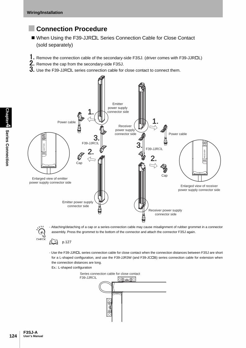
124
Chapter4
Series Connection
F3SJ-AUser’s Manual
Wiring/Installation
Connection Procedure When Using the F39-JJRL Series Connection Cable for Close Contact
(sold separately)
1. Remove the connection cable of the secondary-side F3SJ. (driver comes with F39-JJRL)2. Remove the cap from the secondary-side F3SJ. 3. Use the F39-JJRL series connection cable for close contact to connect them.
- Attaching/detaching of a cap or a series-connection cable may cause misalignment of rubber grommet in a connectorassembly. Press the grommet to the bottom of the connector and attach the connector F3SJ again.
p.127
- Use the F39-JJRL series connection cable for close contact when the connection distances between F3SJ are shortfor a L-shaped configuration, and use the F39-JJR3W (and F39-JCB) series connection cable for extension whenthe connection distances are long. Ex.: L-shaped configuration
2.2.
3.3.
1.1.
1.1.
2.2.
3.3.
Power cable
Power cable
Cap
Cap
F39-JJR L
F39-JJR L
Emitter
power supply
connector side
Emitter power supply
connector side
Receiver power supply
connector side
Receiver
power supply
connector side
Enlarged view of emitter
power supply connector sideEnlarged view of receiver
power supply connector side
EM
ITT
ER
RE
CE
IVE
R
Series connection cable for close contact
F39-JJR L
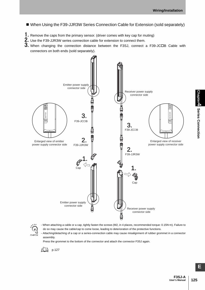
125F3SJ-A
User’s Manual
Chapter4
Series Connection
Wiring/Installation
E
When Using the F39-JJR3W Series Connection Cable for Extension (sold separately)
1. Remove the caps from the primary sensor. (driver comes with key cap for muting)2. Use the F39-JJR3W series connection cable for extension to connect them. 3. When changing the connection distance between the F3SJ, connect a F39-JCB Cable with
connectors on both ends (sold separately).
- When attaching a cable or a cap, tightly fasten the screws (M2, in 4 places, recommended torque: 0.15Nm). Failure todo so may cause the cable/cap to come loose, leading to deterioration of the protective functions.
- Attaching/detaching of a cap or a series-connection cable may cause misalignment of rubber grommet in a connectorassembly.Press the grommet to the bottom of the connector and attach the connector F3SJ again.
p.127
F39-JC B
F39-JC B
1.1.
1.1.
2.2.
2.2.
3.3.
3.3.
F39-JJR3W
F39-JJR3W
Cap
Cap
Emitter power supply
connector side
Emitter power supply
connector sideReceiver power supply
connector side
Receiver power supply
connector side
Enlarged view of emitter
power supply connector side
Enlarged view of receiver
power supply connector side
EM
ITT
ER
RE
CE
IVE
R
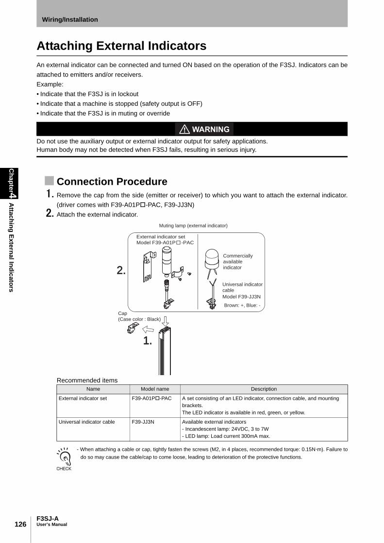
126
Chapter4
Attaching External Indicators
F3SJ-AUser’s Manual
Wiring/Installation
Attaching External IndicatorsAn external indicator can be connected and turned ON based on the operation of the F3SJ. Indicators can beattached to emitters and/or receivers. Example: • Indicate that the F3SJ is in lockout • Indicate that a machine is stopped (safety output is OFF) • Indicate that the F3SJ is in muting or override
Do not use the auxiliary output or external indicator output for safety applications. Human body may not be detected when F3SJ fails, resulting in serious injury.
Connection Procedure 1. Remove the cap from the side (emitter or receiver) to which you want to attach the external indicator.
(driver comes with F39-A01P-PAC, F39-JJ3N)2. Attach the external indicator.
Recommended items
- When attaching a cable or cap, tightly fasten the screws (M2, in 4 places, recommended torque: 0.15Nm). Failure todo so may cause the cable/cap to come loose, leading to deterioration of the protective functions.
Name Model name Description
External indicator set F39-A01P-PAC A set consisting of an LED indicator, connection cable, and mounting brackets. The LED indicator is available in red, green, or yellow.
Universal indicator cable F39-JJ3N Available external indicators- Incandescent lamp: 24VDC, 3 to 7W- LED lamp: Load current 300mA max.
External indicator set
Model F39-A01P -PAC
Model F39-JJ3N
1.1.1.
2.2.
3.
Commercially
available
indicator
Universal indicator
cable
Muting lamp (external indicator)
Cap
(Case color : Black)
Brown: +, Blue: -

127F3SJ-A
User’s Manual
Chapter4
Attaching External Indicators
Wiring/Installation
E
- Attaching/detaching of a cap or a series-connection cable may cause misalignment of rubber grommet in a connectorassembly. Press the grommet to the bottom of the connector and attach the connector F3SJ again.
Output OperationThe external indicator output 1 (on the receiver side) is configured as "safety output reverse output(ON when blocked)", while the external indicator output 2 (on the emitter side) is configured as "lockoutoutput (ON during lockout)".When the muting function is used, both the emitter and receiver are configured as muting/overrideoutput (Blinking during muting and during override).
Timing chart of basic system
Setting Change by the Setting ToolFunctional setting is available through the setting tool.
External Indicator Output (Non-Safety Output) p.99
•Changing output operation mode•Reversing output•Changing indication mode of external indicator•Enabling diagnosis function of external indicator
Rubber Grommet Rubber Grommet
Rubber Grommet in Right Position Misaligned Grommet
Safety outputON
OFF
ON
OFF
ON
OFF
Unblocked
/Blocked
Unblocked
Blocked
Lockout
External indicator output 1
External indicator output 2
( Receiver )
( Emitter )
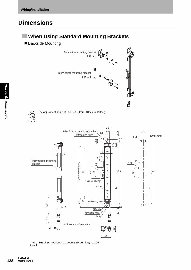
128
Chapter4
Dim
ensions
F3SJ-AUser’s Manual
Wiring/Installation
Dimensions
When Using Standard Mounting Brackets Backside Mounting
The adjustment angle of F39-LJ3 is from -10deg to +10deg.
Bracket mounting procedure (Mounting) p.154
Top/bottom mounting bracket
Intermediate mounting bracket
3.7
5
6.2
5E
13
.75
B A
30
D
2231
205.5
30
16
.5
22
42
2-M5
4-M5
24
30
04
3
1
26
46
EB
13
.75
10
37
42
53
5.5
7
dia. 15
dia. 6
dia. 9
dia. 6.5
2-Top/bottom mounting brackets
2-Mounting holes
2-Mounting holes
M12 Waterproof connector
C (
Pro
tect
ive h
eig
ht)
Intermediate mounting
bracket
2-Mounting holes
4-Mounting holes
Beam
(Unit: mm)
20
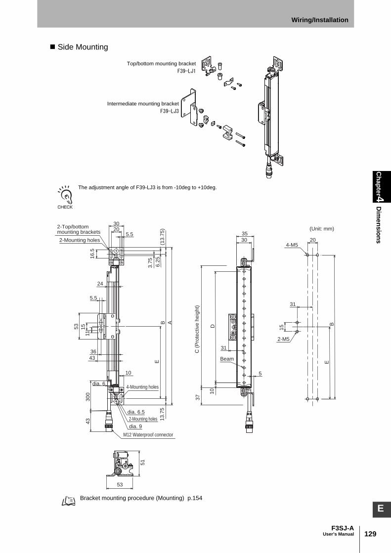
129F3SJ-A
User’s Manual
Chapter4
Dim
ensionsWiring/Installation
E
Side Mounting
The adjustment angle of F39-LJ3 is from -10deg to +10deg.
Bracket mounting procedure (Mounting) p.154
Top/bottom mounting bracket
Intermediate mounting bracket
30
D
31
5
10
35
31
15
EB
20
2-M5
4-M5
3.7
5
6.2
5(1
3.7
5)
BE
13
.75
A
51
53
3020
16
.5
5.5
24
15
11
53
30
04
3
36
10
43
37
5.5
dia. 6
dia. 6.5
dia. 9
2-Top/bottom mounting brackets
2-Mounting holes
2-Mounting holes
4-Mounting holes
M12 Waterproof connector
C (
Pro
tective
he
igh
t)
(Unit: mm)
Beam

130
Chapter4
Dim
ensions
F3SJ-AUser’s Manual
Wiring/Installation
Dimensions A to E
Dimension E
*1. Use E = 530 or less when none of the E values shown above are used.
Dimensions of Standard Brackets (top/bottom mounting brackets)
A C + 74
B C + 46.5
C 4-digit number of the model name (protective height)
D C - 20
E Depends on the protective height. See the table below.
Protective heightNumber of intermediate
mounting bracketsE*1
0245 to 0596 0 -
0600 to 1130 1 B/2
1136 to 1658 2 B/3
1660 to 2180 3 B/4
2195 to 2500 4 B/5
16
230
19.621
10
9
19
.6
8
18
11
5.5
36
.516
.51
4.5
13.5
A-A
A
A
11.5
21
30
10
2-M3Through holes
(Unit: mm)
Material: Stainless steelMaterial: Stainless steel
Material: Brass
5.6
5.5dia. 9
dia. 6.5
2-dia. 3
.5

131F3SJ-A
User’s Manual
Chapter4
Dim
ensionsWiring/Installation
E
When Using Optional Mounting Brackets F39-LJ2 Side-mounting Optional Bracket
Dimensions A to C
A C + 74
B C + 39.5
C 4-digit number of the model name (protective height)
F39-LJ2
Use standard brackets
20
275.5
25
.52
19
37
17
.25
B(1
7.2
5)
A B
4-M5
0.3
9.7 20
35
44
37.6
5
35C
(P
rote
ctive
he
igh
t)
Material: Stainless steel
(Unit: mm)
dia. 6.5
dia.9
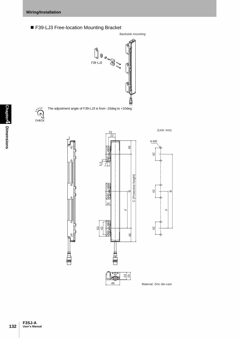
132
Chapter4
Dim
ensions
F3SJ-AUser’s Manual
Wiring/Installation
F39-LJ3 Free-location Mounting Bracket
The adjustment angle of F39-LJ3 is from -10deg to +10deg.
Backside mounting
2231
75.5
24
25
46
45
45
16-M5
F
B
16
F
B
42
42
42
42
53
(Unit: mm)C
(P
rote
ctive
he
igh
t)
Material: Zinc die-cast

133F3SJ-A
User’s Manual
Chapter4
Dim
ensionsWiring/Installation
E
The adjustment angle of F39-LJ3 is from -10deg to +10deg.
Side mounting (when using intermediate brackets for side mounting)
5.5
11
36
43
15
53
51
24
43
30
5
6-M5
16 5
2
45
45
F
B
F
B
15
15
15
(Unit: mm)
C (
Pro
tective
he
igh
t)
Material: Zinc die-cast/stainless steel

134
Chapter4
Dim
ensions
F3SJ-AUser’s Manual
Wiring/Installation
The adjustment angle of F39-LJ3 is from -10deg to +10deg.
When performing side mounting without using intermediate brackets for side mounting, F39-LJ3 brackets cannot beused in combination with standard brackets.
Side mounting (when not using intermediate brackets for side mounting)
(Unit: mm)31
16
24
25
46
45
45
16-M5
F
B
42
42
42
2-dia. 5.5
53 42
13
C (
Pro
tective
he
igh
t)
B
F
Material: Zinc die-cast

135F3SJ-A
User’s Manual
Chapter4
Dim
ensionsWiring/Installation
E
Dimensions B, C, and F
Dimension F
*1. Use F = 350 or less when none of the F values shown above are used.
When only F39-LJ3 free-location mounting brackets are used without standard brackets, allow a spaceof at least 350mm between the brackets. The number of brackets required varies according to theprotective height. For details about the number of required brackets, refer to the table below. The intermediate mounting brackets shipped with the product are the same as the F39-LJ3 free-location mounting brackets. Purchase brackets as necessary if there are fewer intermediate mountingbrackets than required. When intermediate mounting brackets are included, they can be used as free-location mounting brackets.
Required number of F39-LJ3 free-location mounting brackets (2 pieces are included with F39-LJ3) for1 F3SJ set (emitter/receiver)
B C - 90
C 4-digit number of the model name (protective height)
F Depends on the protective height. See the table below.
Protective heightNumber of intermediate
mounting bracketsF*1
245 to 440 2 -
443 to 785 3 B/2
794 to 1140 4 B/3
1145 to 1490 5 B/4
1495 to 1840 6 B/5
1845 to 2180 7 B/6
2195 to 2500 8 B/7
Protective height
Number of free-location mounting brackets included
as intermediate mounting
brackets
Number of free-location mounting brackets required
for mounting F3SJ
Number of additional free-location mounting bracket
sets (number of brackets) that need to be purchased
245 to 440 0 4 2 sets (4)
443 to 596 0 6 3 sets (6)
600 to 785 2 6 2 sets (4)
794 to 1130 2 8 3 sets (6)
1136 to 1140 4 8 2 sets (4)
1145 to 1490 4 10 3 sets (6)
1495 to 1658 4 12 4 sets (8)
1660 to 1840 6 12 3 sets (6)
1845 to 2180 6 14 4 sets (8)
2195 to 2500 8 16 4 sets (8)
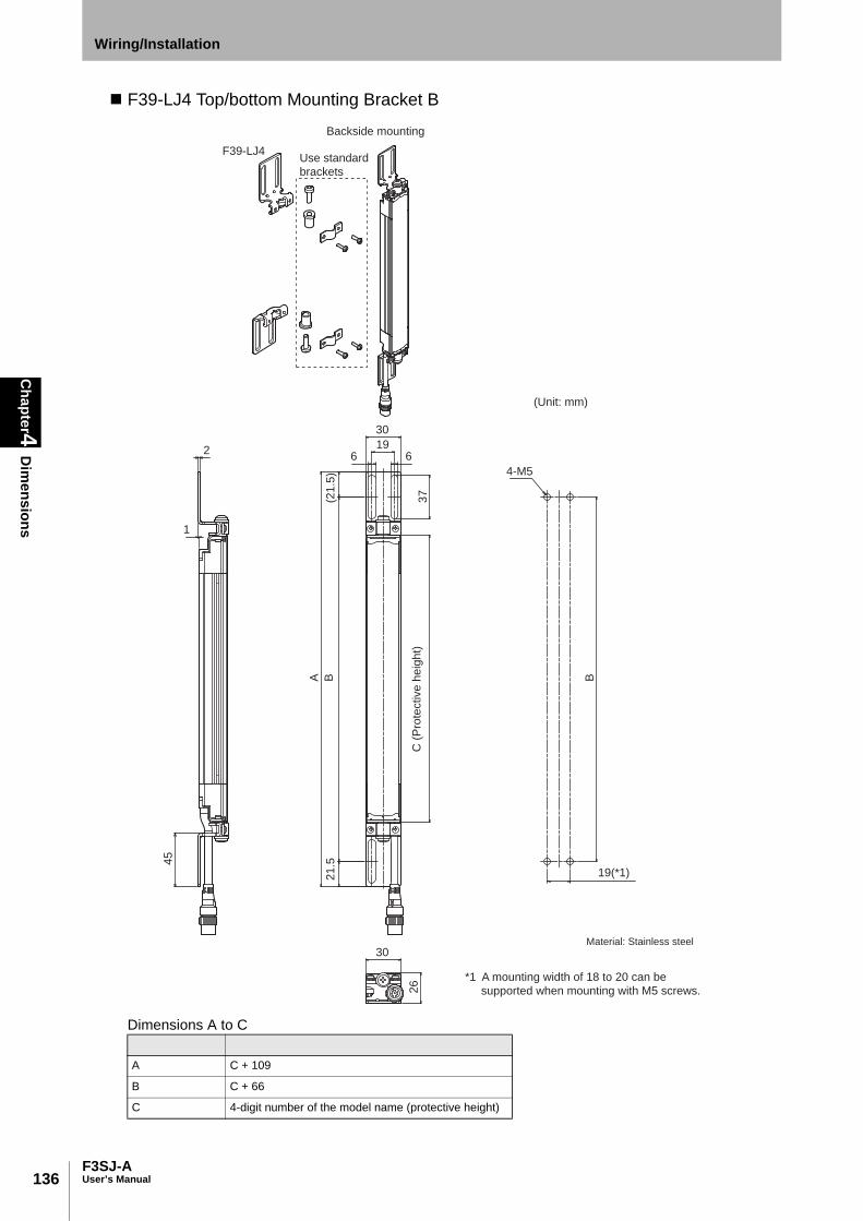
136
Chapter4
Dim
ensions
F3SJ-AUser’s Manual
Wiring/Installation
F39-LJ4 Top/bottom Mounting Bracket B
Dimensions A to C
A C + 109
B C + 66
C 4-digit number of the model name (protective height)
F39-LJ4
196 6
37
2
1
B
19(*1)
30
4-M5
26
A B2
1.5
(21
.5)
30
45
Backside mounting
Use standard
brackets
C (
Pro
tective
he
igh
t)
(Unit: mm)
*1 A mounting width of 18 to 20 can be
supported when mounting with M5 screws.
Material: Stainless steel

137F3SJ-A
User’s Manual
Chapter4
Dim
ensionsWiring/Installation
E
Dimensions A to C
A C + 109
B C + 66
C 4-digit number of the model name (protective height)
F39-LJ4
4-M5
B
19(*1)
196 6
37
AB2
1.5
(21
.5)
30
35
34
5
410
5
30
24
5
Side mounting
Use standard
brackets
C (
Pro
tective
he
igh
t)
(Unit: mm)
Material: Stainless steel
*1 A mounting width of 18 to 20 can be
supported when mounting with M5 screws.

138
Chapter4
Dim
ensions
F3SJ-AUser’s Manual
Wiring/Installation
F39-LJ5 Replacement Bracket for F3SN Use these replacement brackets for an F3SN with a small protective height. (These brackets are designed for use with the F3SN's mounting holes.)
Dimensions A to C
A C + 23
B C - 10
C 4-digit number of the model name (protective height)
F39-LJ5
Inward-facing mounting
Use standard
brackets
5.5 5.520
30
21
32
19.9
20
BB
4-M5
30
2
16
.5(1
6.5
)
A
11
.5C
(P
rote
ctive
he
igh
t)
(Unit: mm)
Material: Stainless steel
dia. 6.5
dia. 9
44.9
44
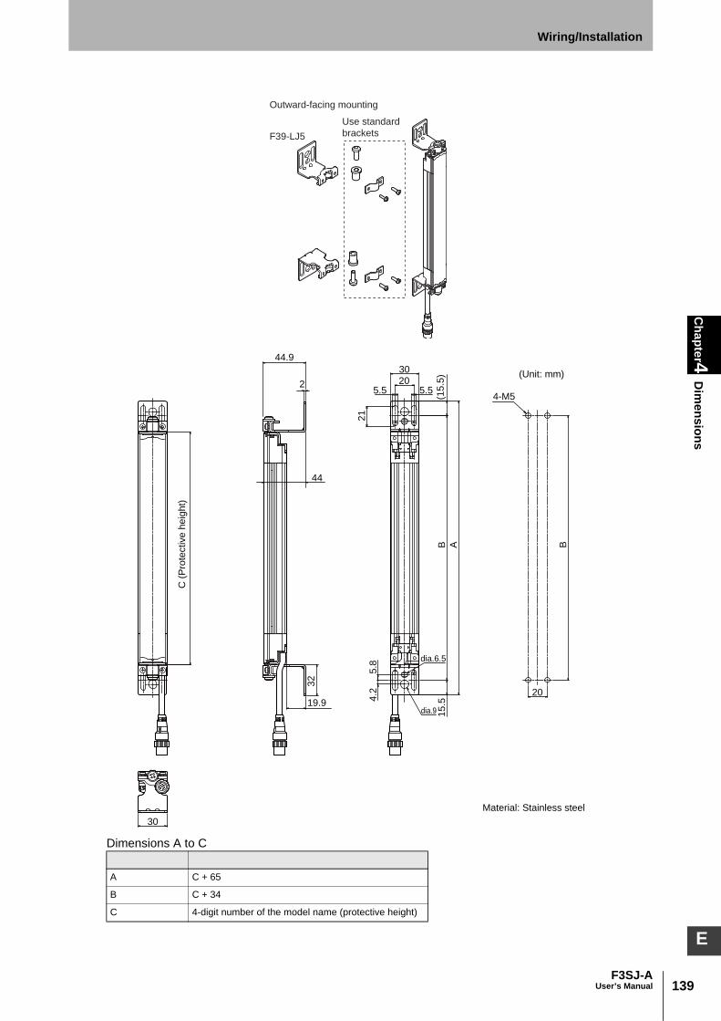
139F3SJ-A
User’s Manual
Chapter4
Dim
ensionsWiring/Installation
E
Dimensions A to C
A C + 65
B C + 34
C 4-digit number of the model name (protective height)
F39-LJ5
Outward-facing mounting
Use standard
brackets
B
20
4-M5
30
205.55.5
21
B
5.8
4.2
A
30
15
.5(1
5.5
)
19.9
32
2
C (
Pro
tective
he
igh
t)
(Unit: mm)
Material: Stainless steel
dia.6.5
dia.9
44
44.9
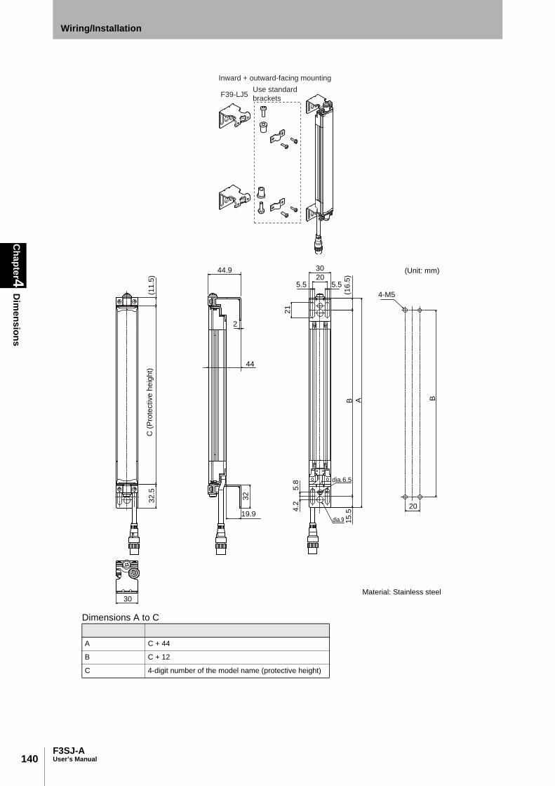
140
Chapter4
Dim
ensions
F3SJ-AUser’s Manual
Wiring/Installation
Dimensions A to C
A C + 44
B C + 12
C 4-digit number of the model name (protective height)
F39-LJ5
Inward + outward-facing mounting
Use standard
brackets
30
19.9
32
32
.5(1
1.5
)
5.8
4.2
15.5
21
B A
(16
.5)
5.5 5.520
30
B
20
4-M5
2
C (
Pro
tective
he
igh
t)
(Unit: mm)
Material: Stainless steel
dia.6.5
dia.9
44
44.9

141F3SJ-A
User’s Manual
Chapter4
Dim
ensionsWiring/Installation
E
F3SN replacement correspondence table (F3SN mounting holes can be used without modification)•When replacing F3SN-P14 with F3SJ-AP14
For lengths greater than the F3SN-0234P14: Add 11 to the F3SN's 4-digit number and apply it as the F3SJ's 4-digit number, and then replace withthe standard brackets included with the product. [Selection example] F3SN-A0315P14 becomes F3SJ-A0326P14 (replace with standard brackets)
- The protective height is 11mm longer. - Replace with outward-facing mounting of F39-LJ5 when you want to set the detection surface height to be same asthe F3SN. However, the F39-LJ5 and intermediate mounting brackets cannot be mounted simultaneously, so set the protectiveheight to 600mm or less.
•When replacing F3SN-P25 with F3SJ-AP20
For lengths greater than the F3SN-0262P25: Subtract 17 from the F3SN's 4-digit number and apply it as the F3SJ's 4-digit number, and thenreplace with the standard brackets included with the product. [Selection example] F3SJ-A0322P25 becomes F3SJ-A0305P20 (replace with standard brackets)
- The protective height becomes 17mm shorter. - Replace with outward-facing mounting of F39-LJ5 when you want to set the detection surface height to be same asthe F3SN. However, the F39-LJ5 and intermediate mounting brackets cannot be mounted simultaneously, so set the protectiveheight to 600mm or less.
F3SN Replacement F3SJ Replacement method using F39-LJ5 Model name Protective height Model name Protective height
F3SN-0153P14 153 - - -
F3SN-0180P14 180 F3SJ-A0245P14 245 Inward-facing mounting
F3SN-0189P14 189 F3SJ-A0245P14 245 Inward-facing mounting
F3SN-0198P14 198 F3SJ-A0245P14 245 Inward + outward-facing mounting
F3SN-0207P14 207 F3SJ-A0245P14 245 Inward + outward-facing mounting
F3SN-0216P14 216 F3SJ-A0245P14 245 Outward-facing mounting
F3SN-0225P14 225 F3SJ-A0245P14 245 Outward-facing mounting
F3SN Replacement F3SJ Replacement method using F39-LJ5 Model name Protective height Model name Protective height
F3SN-0187P25 187 - - -
F3SN-0217P25 217 F3SJ-A0260P20 260 Inward-facing mounting
F3SN-0232P25 232 F3SJ-A0260P20 260 Inward + outward-facing mounting
F3SN-0247P25 247 F3SJ-A0245P20 245 Outward-facing mounting
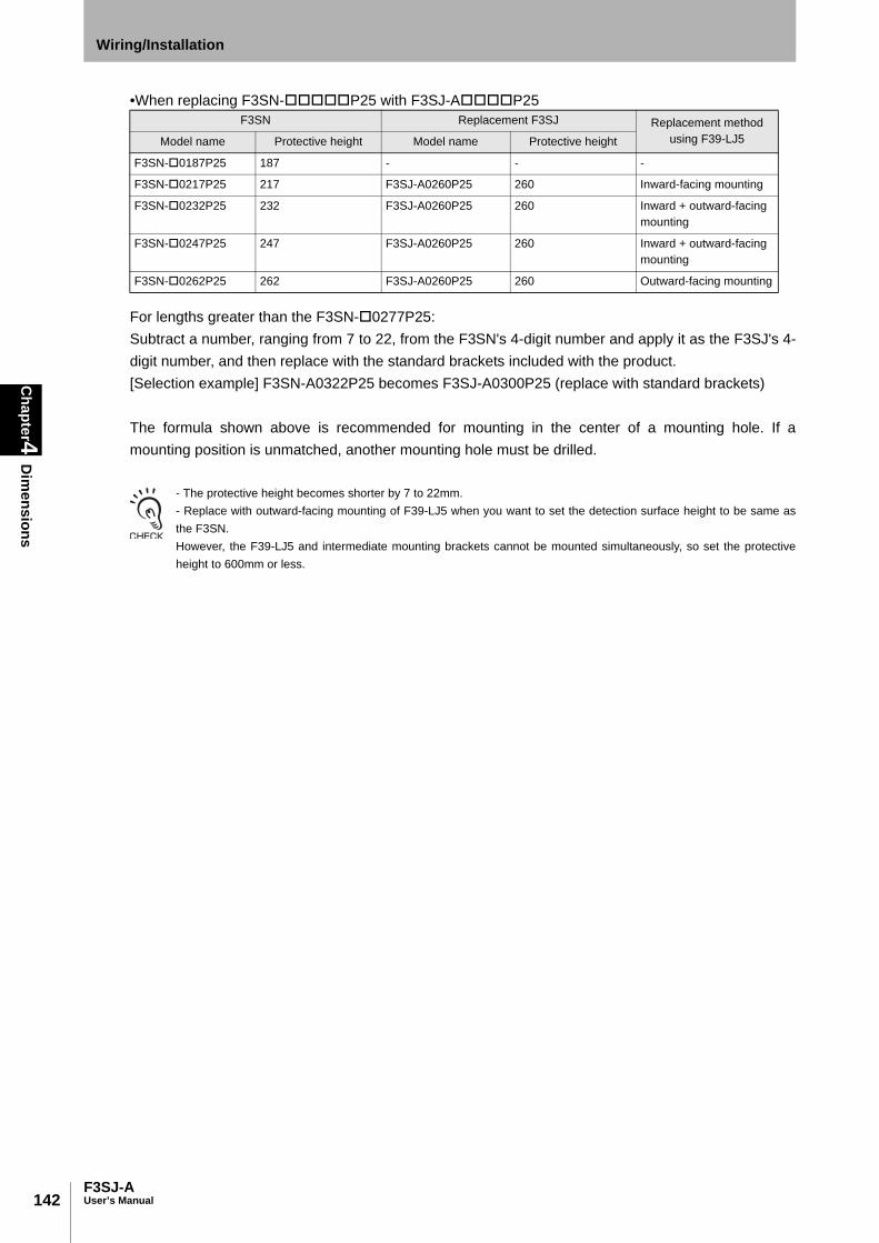
142
Chapter4
Dim
ensions
F3SJ-AUser’s Manual
Wiring/Installation
•When replacing F3SN-P25 with F3SJ-AP25
For lengths greater than the F3SN-0277P25: Subtract a number, ranging from 7 to 22, from the F3SN's 4-digit number and apply it as the F3SJ's 4-digit number, and then replace with the standard brackets included with the product. [Selection example] F3SN-A0322P25 becomes F3SJ-A0300P25 (replace with standard brackets)
The formula shown above is recommended for mounting in the center of a mounting hole. If amounting position is unmatched, another mounting hole must be drilled.
- The protective height becomes shorter by 7 to 22mm. - Replace with outward-facing mounting of F39-LJ5 when you want to set the detection surface height to be same asthe F3SN. However, the F39-LJ5 and intermediate mounting brackets cannot be mounted simultaneously, so set the protectiveheight to 600mm or less.
F3SN Replacement F3SJ Replacement method using F39-LJ5 Model name Protective height Model name Protective height
F3SN-0187P25 187 - - -
F3SN-0217P25 217 F3SJ-A0260P25 260 Inward-facing mounting
F3SN-0232P25 232 F3SJ-A0260P25 260 Inward + outward-facing mounting
F3SN-0247P25 247 F3SJ-A0260P25 260 Inward + outward-facing mounting
F3SN-0262P25 262 F3SJ-A0260P25 260 Outward-facing mounting

143F3SJ-A
User’s Manual
Chapter4
Dim
ensionsWiring/Installation
E
F39-LJ8 Space-saving Mounting BracketBrackets that can save mounting space for top and bottom
Dimensions A to C
The F39-LJ8 and intermediate mounting brackets cannot be mounted simultaneously, so set the protective height to600mm or less.
A C + 23B C - 10.3C 4-digit number of the model name (protective height)
F39-LJ8
Backside mounting
Use standard
brackets
C (
Pro
tective
he
igh
t)
(Unit: mm)
Material: Stainless steel
11.5
33
2
25.6
5
8
16.6
5B
16.6
5
3020
5.55.5
7
A
20
4-M5
B

144
Chapter4
Dim
ensions
F3SJ-AUser’s Manual
Wiring/Installation
F39-LJ9 Mounting Bracket for F3W-C ReplacementUse these brackets to replace F3W-C.
Dimensions A to C
A C + 102.3
B C + 77.3
C 4-digit number of the model name (protective height)
F39-LJ9
Backside mounting
Use standard
brackets
(Unit: mm)
C (
Pro
tective
he
igh
t)
8B
17
16
B
16
66
30
31033
328
69.3
A
4-M5
1
2
26 Material: Stainless steel

145F3SJ-A
User’s Manual
Chapter4
Dim
ensionsWiring/Installation
E
Dimensions A to C
A C + 102.3
B C + 77.3
C 4-digit number of the model name (protective height)
F39-LJ9
Side mounting
Use standard
brackets
(Unit: mm)
16
B
5
24-M5
B8
17
30
66
16
A
31033
69.3
328
10
4
35
C (
Pro
tective
he
igh
t)
Material: Stainless steel

146
Chapter4
Dim
ensions
F3SJ-AUser’s Manual
Wiring/Installation
F3W-C replacement correspondence table (F3W-C mounting holes can be used without modification)•When replacing F3W-C with F3SJ-A30Target F3W-C4
*1 New mounting holes are required for intermediate mounting brackets.
F3SN Replacement F3SJ
Model Protective height Model Protective height
F3W-C044 120 - -
F3W-C084 280 F3SJ-A032030 320
F3W-C124 440 F3SJ-A047030 470
F3W-C164 600 F3SJ-A062030 *1 620
F3W-C204 760 F3SJ-A079530 *1 795
F3W-C244 920 F3SJ-A094530 *1 945

147F3SJ-A
User’s Manual
Chapter4
Dim
ensionsWiring/Installation
E
F39-LJ11 Top/bottom Mounting Bracket C
Dimensions A to C
A C + 109
B C + 69
C 4-digit number of the model name (protective height)
Use standard
brackets
26
20
13
54.534
3
13
30
6
20
54.5
AB B
2
1
4-M5
Hole size for mounting
4-Mounting holes
Material: Stainless steel
(Unit: mm)
C (Protective height)

148
Chapter4
Dim
ensions
F3SJ-AUser’s Manual
Wiring/Installation
F39-A01P-PAC External Indicator Set •F39-A01P-PAC
When Using Spatter Protection Covers Dimensions of the Spatter Protection Cover F39-HJ
Assembly Dimensions
18
90
20
17
3
61
6
619
34
54
232
(Unit: mm)
Material: Stainless steel
L10
32
L= -10 mm
(Unit: mm)
Material: PC (protective cover)
29
.5
32
(Unit: mm)
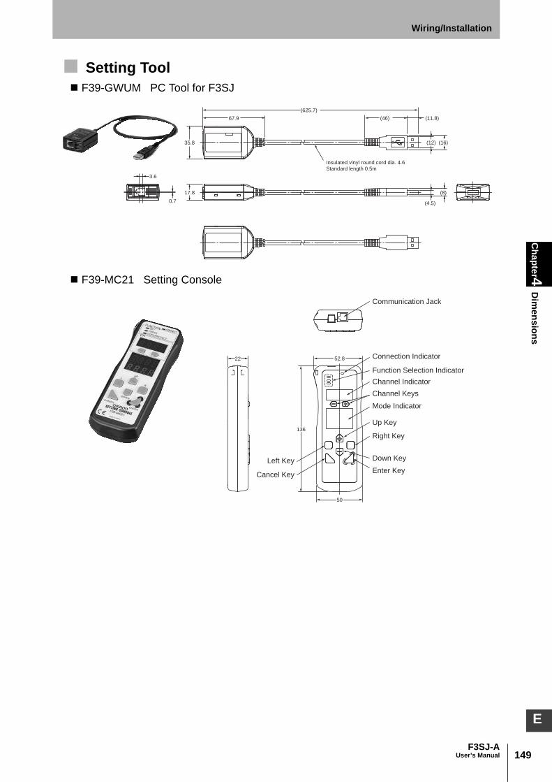
149F3SJ-A
User’s Manual
Chapter4
Dim
ensionsWiring/Installation
E
Setting Tool F39-GWUM PC Tool for F3SJ
F39-MC21 Setting Console
67.9
35.8
17.8
3.6
0.7
(8)
(16)(12)
(4.5)
(625.7)
(46)
(11.8)
Insulated vinyl round cord dia. 4.6
Standard length 0.5m
22 52.8
136
50
Left Key
Cancel Key
Communication Jack
Connection Indicator
Function Selection Indicator
Channel Indicator
Channel Keys
Mode Indicator
Up Key
Right Key
Down Key
Enter Key

150
Chapter4
Dim
ensions
F3SJ-AUser’s Manual
Wiring/Installation
Mounting a Protect Bar External Dimensions of Protect Bar F39-PJ-S
Dimensions A to C Dimension D Protective height Number of used protection brackets (3) D *1
A C+74 245 to 1000 0 -
B C+46.5 1001 to 2000 1 B/2
C 4-digit number of the model name (protective height)
2009 to 2500 2 B/3
*1 D is for reference and must be a length that should not affect intermediate mounting bracket
16.5
5.5
(37)
1
(13.75)
(13.75)
AB
D
69
64
15
(6)
20
43
23
10
20
3024
dia.9
16
8
dia.6.5
(37)
B
M5
39
D
6.25
20
2-M8
2-M6
3.75
3.75 6.25
B
M5
39
D
20
4-M5
20
C(Protective
height)
dia.5.5
(6)
Hole size for mountingProtection Bracket (2)
Protection Bracket (3)
Protection Bracket (1)
Mounting hole
Backside mounting
(Unit: mm)
Using M5 Using M6 and M8
3-M5
Hex. Bolt
with Washer and Hole
Sensor
4-Mounting holes
2-Mounting holes
2-Mounting holes4-M3
Hex. Bolt
with Washer
and Hole
Protection Support
Material: Stainless steel and aluminum
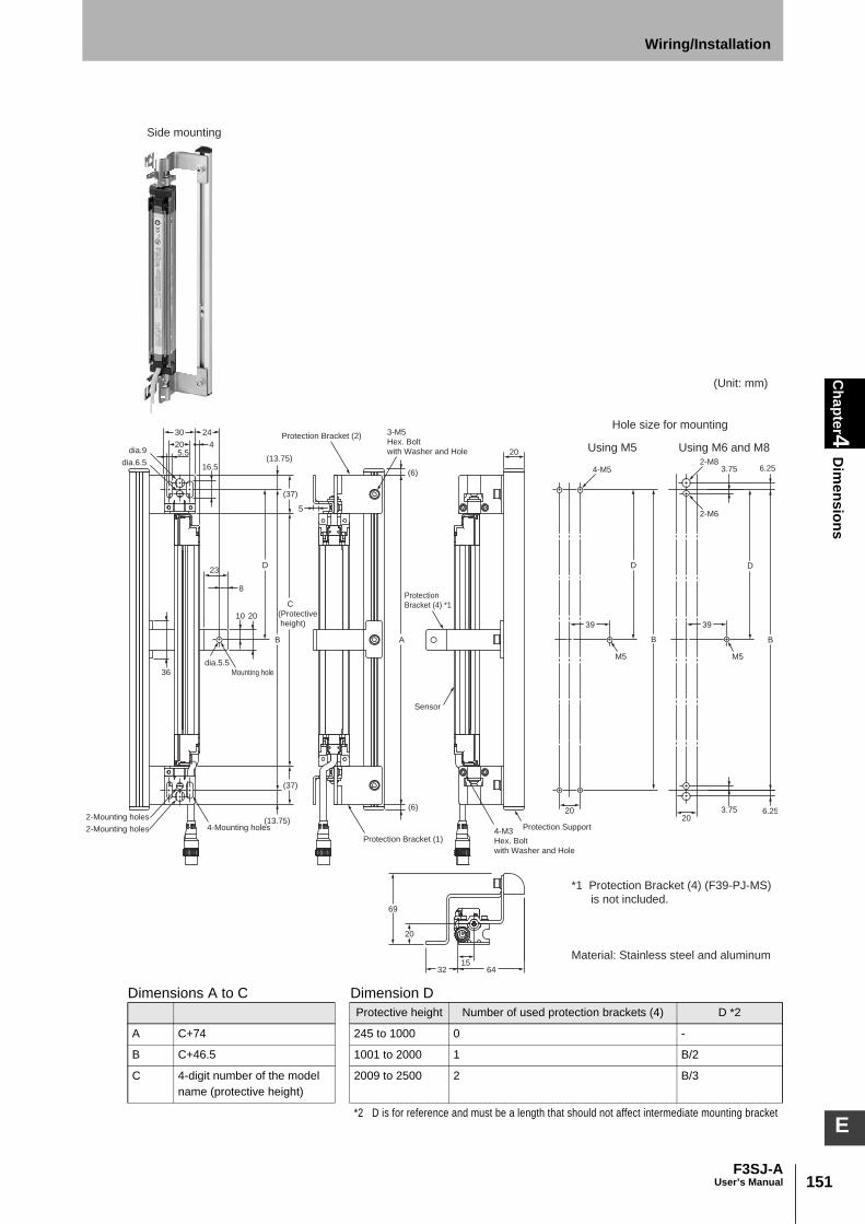
151F3SJ-A
User’s Manual
Chapter4
Dim
ensionsWiring/Installation
E
Dimensions A to C Dimension D Protective height Number of used protection brackets (4) D *2
A C+74 245 to 1000 0 -
B C+46.5 1001 to 2000 1 B/2
C 4-digit number of the model name (protective height)
2009 to 2500 2 B/3
*2 D is for reference and must be a length that should not affect intermediate mounting bracket
16.5
45.5
AB
10 20
36
D
69
643215
(6)
20
20
20
30 24
8
23
5
B
M5
39
D
6.25
20
2-M8
2-M6
3.75
3.75 6.25
B
M5
39
D
20
4-M5
(37)
(37)
(13.75)
(13.75)
dia.5.5
(6)
dia.9
dia.6.5
Side mounting
C
(Protective
height)
Hole size for mounting
Protection
Bracket (4) *1
Protection Bracket (2)
Protection Bracket (1)
Mounting hole
(Unit: mm)
Using M5 Using M6 and M8
3-M5
Hex. Bolt
with Washer and Hole
Sensor
4-Mounting holes
2-Mounting holes
2-Mounting holes Protection Support
Material: Stainless steel and aluminum
4-M3
Hex. Bolt
with Washer and Hole
*1 Protection Bracket (4) (F39-PJ-MS)
is not included.

152
Chapter4
Dim
ensions
F3SJ-AUser’s Manual
Wiring/Installation
Mounting an Environment-Resistant Case External Dimensions of Environment-Resistant Case F39-EJ
Dimensions A to D
A C+108
B C+76
C 4-digit number of the model name (protective height)
D C+44
13.5
5.5
20
32
dia.6.5
16
16
2
8
dia. 9
dia. 60.5
A B D
32
22
8
2
2-M8
2-M6
2020
8
2
4-M5
B B
Backside mounting
Hole size for mounting
(Unit: mm)
Using M5 Using M6 and M8
Material: Acrylic resin, nitrile rubber, stainless steel
2-Mounting brackets
(F39-EJ-R) *1
C
(Protective
height)
*1 Mounting Bracket (F39-EJ-R) is not included.
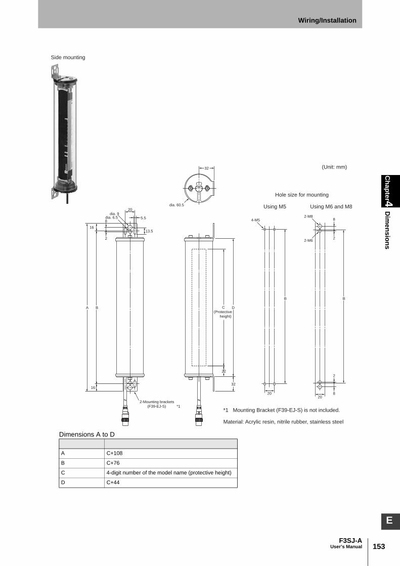
153F3SJ-A
User’s Manual
Chapter4
Dim
ensionsWiring/Installation
E
Dimensions A to D
A C+108
B C+76
C 4-digit number of the model name (protective height)
D C+44
13.5
5.5
20
dia. 6.5
16
16
2
8
dia. 9
DBA
B B
32
22
32
dia. 60.5
8
2
2-M8
2-M6
2020
8
2
4-M5
Side mounting
Hole size for mounting
(Unit: mm)
Using M5 Using M6 and M8
Material: Acrylic resin, nitrile rubber, stainless steel
2-Mounting brackets
(F39-EJ-S) *1
C
(Protective
height)
*1 Mounting Bracket (F39-EJ-S) is not included.

154
Chapter4
Mounting
F3SJ-AUser’s Manual
Wiring/Installation
Mounting The procedures for using standard mounting brackets (included) are explained in this section.
Top/Bottom Mounting Brackets
Intermediate Mounting Brackets The number of intermediate mounting brackets included with F3SJ of various protective heights isshown below.
- To use other mounting bracket or bolt than those for F3SJ, you must confirm that their sizes should match F3SJ.Especially when you do not use top/bottom mounting brackets (2), you may need screws with appropriate lengthbecause the standard mounting screws (M5 x 20) may be too long.
- If the protective height is 600 mm or more, use intermediate mounting brackets of specified quantities and locationsaccording to the dimensions.If the brackets described above are not used, ratings and performance cannot be not met.
Protective heightNumber of
intermediate mounting brackets
0245 to 0596 0
0600 to 1130 1
1136 to 1658 2
1660 to 2180 3
2195 to 2500 4
Mounting screws (M5x20) x 4
Top/bottom mounting bracket (3) x 4
Top/bottom mounting bracket (1) x 4 Top/bottom mounting bracket (2) x 4
Mounting screws (M3x8) x 8 *1 The quantities shown here are the number of parts included in 1 top/bottom mounting bracket set
Material: Stainless steel (top/bottom mounting bracket (1), (3)) Brass (top/bottom mounting bracket (2)) Iron (mounting screws)
Side mounting intermediate brackets x 2(These brackets are used only for side mounting.)
Intermediate brackets (1) x 2
Mounting screws (M5x10) x 4
Intermediate brackets (2) x 2
Intermediate brackets (3) x 2
Intermediate brackets (4) x 2
Mounting screws (M3x10) x 2
Mounting screws (M4x25) x 4* The quantities shown here are the number of parts included in1 intermediate mounting bracket set
Material: Stainless steel (intermediate mounting bracket) Zinc die-cast (Intermediate mounting brackets (1) to (4)) Iron (mounting screws)

155F3SJ-A
User’s Manual
Chapter4
Mounting
Wiring/Installation
E
Mounting Procedure
1. Attach the top/bottom mounting brackets. Place top/bottom mounting bracket (2) in the screw hole at the top/bottom of the F3SJ, and fasten itusing the included screw (M5x20). Insert the bracket's protrusion into the groove on the case whenattaching. Next, attach top/bottom mounting brackets (3) and (1) to top/bottom mounting bracket (2),and fasten them lightly using the included screws (M3x8).
2. Attach the intermediate mounting brackets. Insert intermediate brackets (2) and (3) into the grooves on the side of the case, and use the includedmounting screws (M3x10) to lightly fasten the brackets so that they are able to slide up and down thecase.
Mounting screw
(M5x20)
Top/bottom
mounting
bracket (2)
Mounting screw
(M3x8)
Top/bottom
mounting
bracket (3)
Top/bottom mounting
bracket (1)
Tighten lightly
Mounting
screw
(M3x10)
Intermediate
mounting
bracket (2)
Intermediate
mounting
bracket (3)
Attach so that the tooth shown in the dotted
circle is facing downward.
Tighten
lightly

156
Chapter4
Mounting
F3SJ-AUser’s Manual
Wiring/Installation
3. Attach the intermediate mounting brackets (for backside mounting). For backside mounting, first lightly attach intermediate mounting bracket (1) to the equipment, wallsurface, etc. Then, attach intermediate brackets (1) and (4) to the bracket that was lightly attached tothe case in step 2 above, and lightly tighten them using the included mounting screws (M4x25).
4. Attach the intermediate mounting brackets (for side mounting). When performing side mounting, first attach the intermediate mounting bracket for side mounting tointermediate mounting bracket (1), using the included mounting screws (M5x10). Then, lightly attachintermediate mounting bracket (4) to the bracket that was lightly attached to the case in step 2 above,using the included mounting screws (M4x25).
Intermediate
mounting
bracket (1)
Intermediate
mounting
bracket (4)
Mounting screw
(M4x25)
Intermediate
mounting
bracket (1) Tighten lightly
Intermediate
mounting
bracket (1) Intermediate
mounting
bracket (4)
Mounting screw
(M4x25)
Intermediate mounting
bracket for
side mounting
Mounting screw
(M5x10)
Tighten lightly

157F3SJ-A
User’s Manual
Chapter4
Mounting
Wiring/Installation
E
5. Fasten to equipment. Attach top/bottom mounting bracket (1) to the equipment, wall surface, etc. If you are using anintermediate mounting bracket for side mounting, also attach the side-mounting intermediate bracketto the equipment, wall surface, etc. After the F3SJ is mounted, securely tighten the mounting screws(M3x10) that were lightly tightened in step 2 above.
6. Adjust the beams. Move the F3SJ from side to side to align it to a center position where the 5 lamps of the incident lightlevel indicator are turned ON. After each screw is securely tightened after beam adjustment, makesure that the 5 lamps of the incident light level indicator are turned ON.
Do not fully tighten the screws one by one. Tighten all screws evenly.
Mounting is complete.For adjustment of beams and tightening torque, see "Adjustment Procedure" inthe next page.
Backside mounting Side mounting
Tighten securely
Tighten securely
Tighten securely

158
Chapter4
Mounting
F3SJ-AUser’s Manual
Wiring/Installation
Adjustment Procedure1. Check the following points:
- The optical surface of the emitter and receiver should be clean.- There should be no interrupting object in the detection zone of the F3SJ.
2. Adjust the emitter's beams. Adjust the angle of the emitter while checking the incident light level indicator, and align the emitter sothat it faces the center position where the incident light level indicator turns ON.
3. Adjust the receiver's beams. Adjust the angle of the receiver while checking the incident light level indicator, and align the receiverso that it faces the center position where the incident light level indicator turns ON.
4. Make sure that all 5 lamps of the incident light level indicator are turned ON.
5. While taking care not to change the adjustment status of the beams, tightly fasten all the bracketscrews and mounting screws. The table below shows the tightening torques for the included screws.
- If some of the 5 lamps of the incident light level indicator are not turned ON even when the receiver angle is adjusted,check whether or not the mounting surfaces of the emitter/receiver are parallel, and whether or not the mountingheight of the emitter/receiver is appropriate.
- You must comply with specified tightening torque and screw sizes. Otherwise a failure may occur.
Mounting bracket type Nominal diameter x length of
screw (mm)Tightening torque
Top/bottom mounting brackets
M3x8 0.54Nm
M5x18 2.3Nm
Intermediate mounting brackets
M3x10 0.54Nm
M4x25 1.2Nm
M5x10 2.3Nm

159F3SJ-A
User’s Manual
Chapter4
Wiring
Wiring/Installation
E
Wiring
Wiring Precautions
Double or reinforced insulation from hazardous voltage must be applied to all input and output lines. Failure to do so may result in electric shock.
Connect the load between the output and 0V line. (PNPoutput) Connecting between the output and +24V line is dangerous because the operation mode is reversed to "ON when blocked".
Do not short-circuit the output line to the +24V line. Otherwise, the output is always ON. Also, the 0V of the power supply must be grounded so that output does not turn ON due to grounding of the output line.
Configure the system by using the optimal number of safety outputs that satisfy the requirements of the necessary safety category.
Do not connect each line of F3SJ to a DC power supply higher than 24V+20%. Also, do not connect to an AC power supply. Failure to do so may result in electric shock.
+24 V
0 V
+24 V
0 V
Brown
Green, White
Blue
Receiver
F3SJ
Brown
Green, White
Blue
Load
Load
F3SJ
Receiver
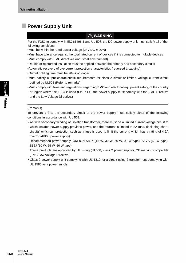
160
Chapter4
Wiring
F3SJ-AUser’s Manual
Wiring/Installation
Power Supply Unit
For the F3SJ to comply with IEC 61496-1 and UL 508, the DC power supply unit must satisfy all of the following conditions: •Must be within the rated power voltage (24V DC ± 20%)•Must have tolerance against the total rated current of devices if it is connected to multiple devices•Must comply with EMC directives (industrial environment)•Double or reinforced insulation must be applied between the primary and secondary circuits•Automatic recovery of overcurrent protection characteristics (reversed L sagging)•Output holding time must be 20ms or longer•Must satisfy output characteristic requirements for class 2 circuit or limited voltage current circuit
defined by UL508 (Refer to remarks)•Must comply with laws and regulations, regarding EMC and electrical equipment safety, of the country
or region where the F3SJ is used (Ex: In EU, the power supply must comply with the EMC Directiveand the Low Voltage Directive.)
(Remarks)To prevent a fire, the secondary circuit of the power supply must satisfy either of the followingconditions in accordance with UL 508: • As with secondary winding of isolation transformer, there must be a limited current voltage circuit to
which isolated power supply provides power, and the "current is limited to 8A max. (including short-circuit)" or "circuit protection such as a fuse is used to limit the current, which has a rating of 4.2Amax." (24VDC power supply). Recommended power supply: OMRON S82K (15 W, 30 W, 50 W, 90 W type), S8VS (60 W type),S82J (10 W, 25 W, 50 W type) These products are approved by UL listing (UL508, class 2 power supply), CE marking compatible(EMC/Low Voltage Directive).
• Class 2 power supply unit complying with UL 1310, or a circuit using 2 transformers complying withUL 1585 as a power supply.

161F3SJ-A
User’s Manual
Chapter4
Wiring
Wiring/Installation
E
Wiring Procedure1. Connect an emitter cable (F39-JC-L, grey, sold separately) to the emitter's connection cable (grey).
2. Connect a receiver cable (F39-JC-D, black, sold separately) to the receiver's connection cable(black).
3. Connect the 0V line of the power supply directly to the protective earth (PE).
To ensure proper wiring, check that the color of the cable matches the color of the connector's resin cover (emitter: grey,receiver: black). Failure to do so may result in damage to the F3SJ. Incorrect wiring can be prevented by matching thecolors.
Cable with Connector on One End (F39-JCA, sold separately)
Internal wiring diagram (F39-JCA-L, F39-JCA-D)
Set model name For emitter For receiver L (mm)
F39-JC3A F39-JC3A-L Grey cable F39-JC3A-D Black cable 3000
F39-JC7A F39-JC7A-L F39-JC7A-D 7000
F39-JC10A F39-JC10A-L F39-JC10A-D 10000
F39-JC15A F39-JC15A-L F39-JC15A-D 15000
F39-JC20A F39-JC20A-L F39-JC20A-D 20000
dia
.15
39.5 L
8-wire (4-pair) (Cross section of conductor: 0.3mm2/insulator diameter: dia. 1.15mm)
(Unit: mm)
M12 Waterproof connectorInsulated vinyl round cable dia. 6.6, shielded
1
2
3
4
5
6
7
8
+24V DC
0V
+24V DC
0V
Emitter Receiver
Female
White
Brown
Green
Grey
Pink
Blue
Red
Shield Shield
Yellow
White
Brown
Green
Grey
Pink
Blue
Red
Yellow
Twisted pair wires are white and red, brown and blue, green and yellow, and grey and pink
Interlock selection input
Test input
Reset input
Auxiliary output 2 External device monitoring input
Control output 1
Safety output 2
Auxiliary output 1
Communication line (+)
Communication line (-)
Communication line (+)
Communication line (-)5
84
3
21
7
6
Connected to connection cable and
Cable with connectors on both ends
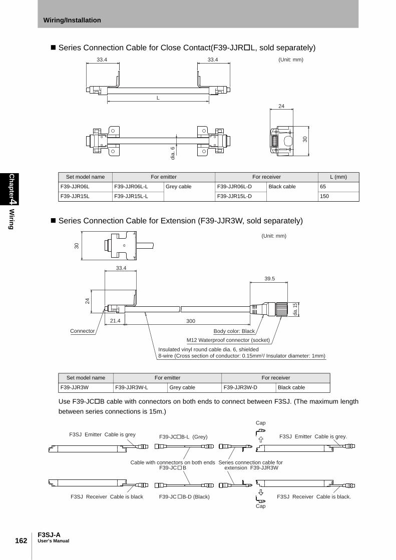
162
Chapter4
Wiring
F3SJ-AUser’s Manual
Wiring/Installation
Series Connection Cable for Close Contact(F39-JJRL, sold separately)
Series Connection Cable for Extension (F39-JJR3W, sold separately)
Use F39-JCB cable with connectors on both ends to connect between F3SJ. (The maximum lengthbetween series connections is 15m.)
Set model name For emitter For receiver L (mm)
F39-JJR06L F39-JJR06L-L Grey cable F39-JJR06L-D Black cable 65
F39-JJR15L F39-JJR15L-L F39-JJR15L-D 150
Set model name For emitter For receiver
F39-JJR3W F39-JJR3W-L Grey cable F39-JJR3W-D Black cable
L
33.433.4
dia
. 6
24
30
(Unit: mm)
30
33.4
21.4
24
39.5
300
(Unit: mm)
Body color: Black
M12 Waterproof connector (socket)
Insulated vinyl round cable dia. 6, shielded
8-wire (Cross section of conductor: 0.15mm2/ Insulator diameter: 1mm)
Connector
dia.
15
F39-JC B-L (Grey)
F39-JC B-D (Black)
Cap
Cap
F3SJ Emitter Cable is grey.
Cable with connectors on both endsF39-JC B
Series connection cable for extension F39-JJR3W
F3SJ Receiver Cable is black F3SJ Receiver Cable is black.
F3SJ Emitter Cable is grey
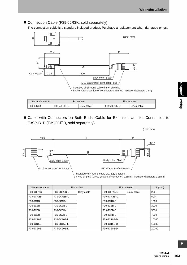
163F3SJ-A
User’s Manual
Chapter4
Wiring
Wiring/Installation
E
Connection Cable (F39-JJR3K, sold separately) The connection cable is a standard included product. Purchase a replacement when damaged or lost.
Cable with Connectors on Both Ends: Cable for Extension and for Connection toF3SP-B1P (F39-JCB, sold separately)
Set model name For emitter For receiver
F39-JJR3K F39-JJR3K-L Grey cable F39-JJR3K-D Black cable
Set model name For emitter For receiver L (mm)
F39-JCR2B F39-JCR2B-L Grey cable F39-JCR2B-D Black cable 200
F39-JCR5B F39-JCR5B-L F39-JCR5B-D 500
F39-JC1B F39-JC1B-L F39-JC1B-D 1000
F39-JC3B F39-JC3B-L F39-JC3B-D 3000
F39-JC5B F39-JC5B-L F39-JC5B-D 5000
F39-JC7B F39-JC7B-L F39-JC7B-D 7000
F39-JC10B F39-JC10B-L F39-JC10B-D 10000
F39-JC15B F39-JC15B-L F39-JC15B-D 15000
F39-JC20B F39-JC20B-L F39-JC20B-D 20000
30
4333.4
21.4
24
300
(Unit: mm)
Body color: Black
M12 Waterproof connector (plug)
Connector
Insulated vinyl round cable dia. 6, shielded
8-wire (Cross section of conductor: 0.15mm2/ Insulator diameter: 1mm)
dia.
15
M12
39.5 L 43
dia
. 1
5
dia
. 1
5
M12 Waterproof connector
(Unit: mm)
Body color: BlackBody color: Black
M12 Waterproof connector
Insulated vinyl round cable dia. 6.6, shielded
8-wire (4-pair) (Cross section of conductor: 0.3mm2/ Insulator diameter: 1.15mm)

164
Chapter4
Wiring
F3SJ-AUser’s Manual
Wiring/Installation
Internal wiring diagram (F39-JCB-L, F39-JCB-D)
If the length of the F39-JCA cable with connector on one end is insufficient, use 1 or more F39-JCB cable with connectors on both ends to extend the length, as required. Connection example
Cable with Connectors on Both Ends: Cable for Connection with G9SA-300-SC (F39-JCC, sold separately)
*1 Use only 1 set of F39-JCoC. If the cable length is insufficient, use F39-JCB for extension so that F39-JCC should be onthe side of G9SA-300-SC.
Set model name *1 For emitter For receiver L (mm)
F39-JCR2C F39-JCR2C-L Grey cable F39-JCR2C-D Black cable 200
F39-JC1C F39-JC1C-L F39-JC1C-D 1000
F39-JC3C F39-JC3C-L F39-JC3C-D 3000
F39-JC7C F39-JC7C-L F39-JC7C-D 7000
F39-JC10C F39-JC10C-L F39-JC10C-D 10000
F39-JC15C F39-JC15C-L F39-JC15C-D 15000
1
2
3
4
5
6
7
8
1
2
3
4
5
6
7
8
White
Brown
Green
Yellow
Grey
Pink
Blue
Red
Shield
Female
Connected to single-end connector cable, Cable
with connectors on both ends, Controller F3SP-B1P
White
Brown
Green
Yellow
Grey
Pink
Blue
Red
Shield
Male
Twisted pair wires are white and red, brown and blue, green and yellow, and grey and pink
Connected to connection cable and
Cable with connectors on both ends
Emitter
Receiver
Cable is grey
Cable is black Model F39-JC A-D(Black)
Model F39-JC B-L(Grey) Model F39-JC A-L(Grey)
Cable with connectors on both ends
Model F39-JC
Cable with connector on one end
Model F39-JC A
Model F39-JC B-D(Black)
M12
39.5 L 43
dia
. 1
5
dia
. 1
5
(Unit: mm)
Body color: GreyBody color: Grey
M12 Waterproof connectorM12 Waterproof connector
Insulated vinyl round cable dia. 6.6, shielded
8-wire (4-pair) (Cross section of conductor: 0.3mm2/ Insulator diameter: 1.15mm)
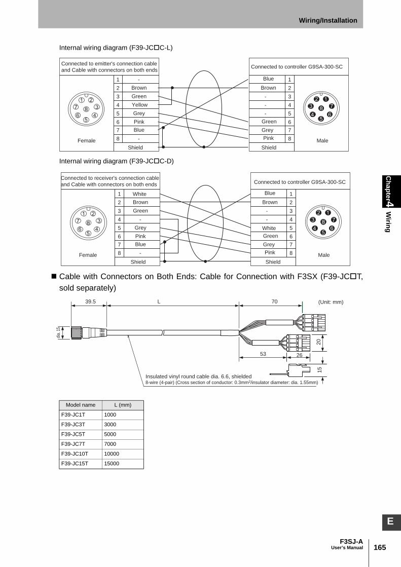
165F3SJ-A
User’s Manual
Chapter4
Wiring
Wiring/Installation
E
Internal wiring diagram (F39-JCC-L)
Internal wiring diagram (F39-JCC-D)
Cable with Connectors on Both Ends: Cable for Connection with F3SX (F39-JCT,sold separately)
Model name L (mm)
F39-JC1T 1000
F39-JC3T 3000
F39-JC5T 5000
F39-JC7T 7000
F39-JC10T 10000
F39-JC15T 15000
1
2
3
4
5
6
7
8
1
2
3
4
5
6
7
8
-
-
-
-
-
Female
Brown
Green
Yellow
Grey
Pink
Blue
Shield
Grey
Green
Brown
Pink
Blue
Shield
Connected to controller G9SA-300-SC
Male
Connected to emitter's connection cable
and Cable with connectors on both ends
-
-
-
-
1
2
3
4
5
6
7
8
1
2
3
4
5
6
7
8Female
Brown
Green
White
WhiteGrey
Pink
Blue
Shield
Grey
Green
Brown
Pink
Blue
Shield
Male
Connected to controller G9SA-300-SCConnected to receiver's connection cable
and Cable with connectors on both ends
39.5
20
15
dia.
15
L 70
53 26
(Unit: mm)
Insulated vinyl round cable dia. 6.6, shielded8-wire (4-pair) (Cross section of conductor: 0.3mm2/insulator diameter: dia. 1.55mm)
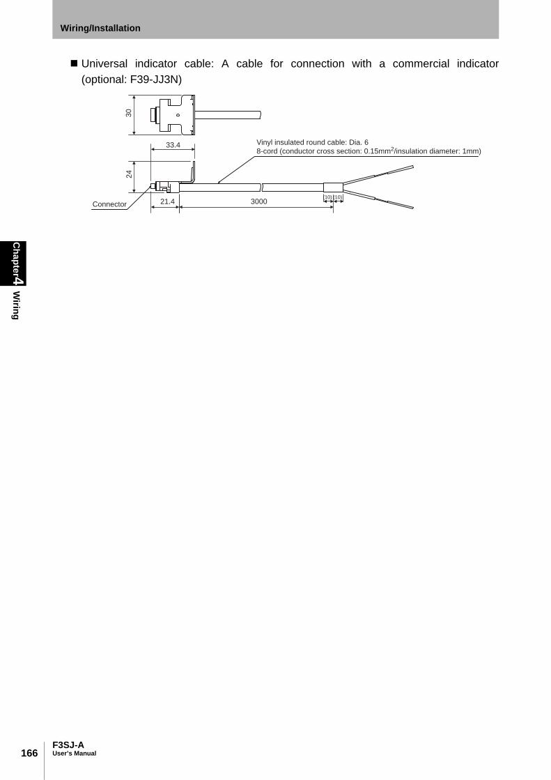
166
Chapter4
Wiring
F3SJ-AUser’s Manual
Wiring/Installation
Universal indicator cable: A cable for connection with a commercial indicator(optional: F39-JJ3N)
21.4
33.4
3000(10) (10)
Vinyl insulated round cable: Dia. 6
8-cord (conductor cross section: 0.15mm2/insulation diameter: 1mm)
30
24
Connector
Chapter5
Input/Output C
ircuit and Applications
167F3SJ-A
User’s Manual
E
Chapter5 Input/Output Circuit and Applications
Input/Output Circuit 168
Wiring Examples 169
Using only F3SJ 169Connecting 2 Muting Sensors 170Connecting 4 Muting Sensors 171Connecting to an F3SP-B1P 172Connecting to an F3SX-E-L2R2 173Connecting to a G9SA-301 175Connecting to a G9SA-300-SC 176Connecting to a G9SB-301-D 177Connecting to a G9SX-AD322-T15 178
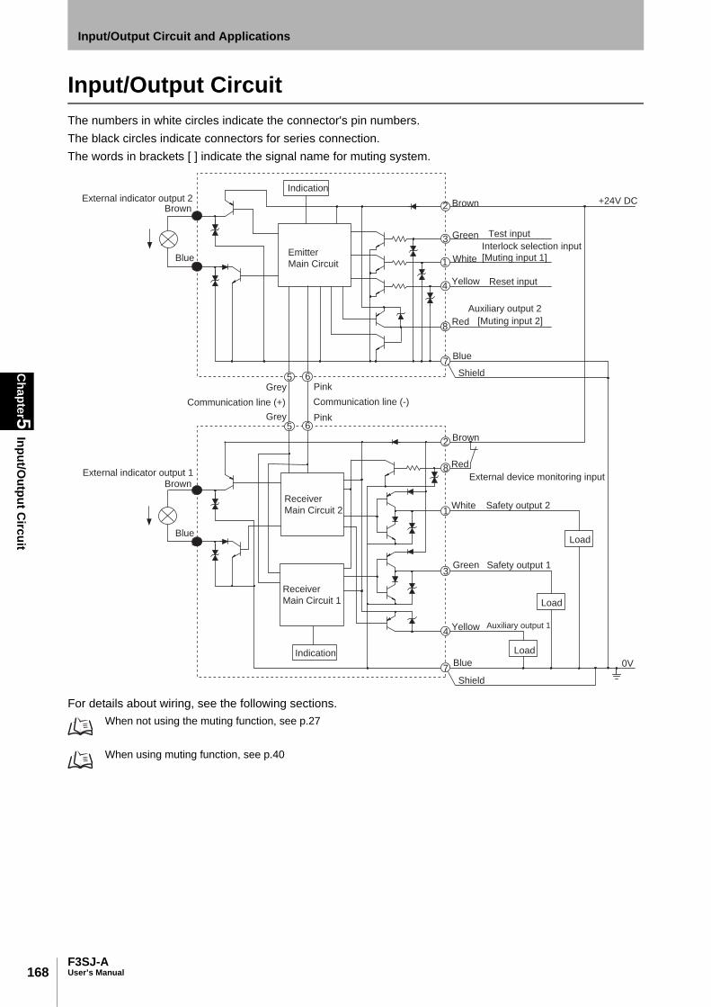
168
Chapter5
Input/Output C
ircuit
F3SJ-AUser’s Manual
Input/Output Circuit and Applications
Input/Output CircuitThe numbers in white circles indicate the connector's pin numbers. The black circles indicate connectors for series connection. The words in brackets [ ] indicate the signal name for muting system.
For details about wiring, see the following sections. When not using the muting function, see p.27
When using muting function, see p.40
Auxiliary output 2
Shield
Shield
+24V DC
0V
5
10
5
10
2
8
1
2
3
1
4
7
8
5
5 6
6
3
4
7
Emitter
Main Circuit
Indication
Receiver
Main Circuit 2
Communication line (-)
Pink
Grey
Grey
Pink
Communication line (+)
External indicator output 1
External indicator output 2Brown
Green Test input
White
Interlock selection input
[Muting input 1]
Red [Muting input 2]
Reset inputYellow
Yellow
Blue
Blue
Blue
Brown
Brown
Brown
Auxiliary output 1
Green Safety output 1
Red
External device monitoring input
White Safety output 2
Blue
Load
Load
LoadIndication
Receiver
Main Circuit 1

169F3SJ-A
User’s Manual
Chapter5
Wiring Exam
plesInput/Output Circuit and Applications
E
Wiring ExamplesSome examples of a motor control system using F3SJ are shown. The category of these systems defined byEN954-1 is 4.
Using only F3SJ•Use of relay contact welding detection and interlock is possible without a controller or relay unit
- Wiring for Auto Reset Mode p.28 - Wiring When External Device Monitoring Function Is Not Used p.28
PLC input *
OUT
PLC
IN
S1
S2
KM1
KM2KM1 KM2
E1
+DC24V
0V
M
KM2
KM1
KM4
F39-JC A-L F39-JC A-D
Emitter Receiver
Communicationline (+) (Grey)
Communicationline (-) (Pink)
Shie
ld
0V
(B
lue)
Test in
put (G
reen)
Reset in
put (Y
ello
w)
Inte
rlock s
ele
ction input (W
hite)
+24V
(B
row
n)
+24V
(B
row
n)
Exte
rna
l d
evic
e m
on
ito
rin
g in
pu
t (R
ed
)
Auxili
ary
outp
ut 1 (
Yelll
ow
)
Safe
ty o
utp
ut 1 (
Gre
en)
Safe
ty o
utp
ut 2 (
White
)
0V
(B
lue)
Shie
ld
- Manual reset mode
S1 :External test switch (connect to 0V if a switch is not required)
S2 :Interlock/lockout reset switch
KM1, KM2 :Safety relay with forcibly-guided contact (G7SA) or
magnetic contactor
KM3 : Load or PLC (for monitoring)
KM4 :Solid state contactor (G3J)
M :3-phase motor
E1 :24VDC power supply (S82K)
PLC :Programmable controller
(Used for monitoring -- not related to safety system)
- Using external device monitoring function
Unblocked
Blocked
External test switch (S1)
Reset switch (S2)
Safety output
KM1,KM2 N.O. contact
KM1,KM2 N.C. contact
PLC output
KM3
Auxili
ary
outp
ut 2 (
Red)
* Output operation mode of auxiliary output 1 is "safety output information/reverse enabled" (initial setting)

170
Chapter5
Wiring Exam
ples
F3SJ-AUser’s Manual
Input/Output Circuit and Applications
Connecting 2 Muting Sensors• Attaching a key cap for muting (F39-CN6) enables the muting function to be used
Attaching the key cap for muting (F39-CN6) p.36
Wiring When External Device Monitoring Function Is Not Required p.41 Using the setting tool enables the use of start interlock and restart interlock.
Interlock Function p.100
F39-JC A-L F39-JC A-D
OUT
PLC
IN
S1
S2
KM1
KM2
KM1 KM2
E1
+DC24V
0V
M
KM2
KM1
KM3
(PNP output)
Emitter Receiver
Communicationline (+) (Grey)
Communicationline (-) (Pink)
Sh
ield
0V
(B
lue
)
Muting input 2 (
Red)
Test in
put (G
reen)
Reset in
put (Y
ello
w)
Muting input 1 (
White)
+2
4V
(B
row
n)
Reflector
Muting sensor
+2
4V
(B
row
n)
Exte
rna
l d
evic
e m
on
ito
rin
g in
pu
t (R
ed
)
Au
xilia
ry o
utp
ut
1 (
Ye
llow
)
Safe
ty o
utp
ut
1 (
Gre
en
)
Safe
ty o
utp
ut
2 (
Wh
ite)
0V
(B
lue
)
Sh
ield
- Auto reset mode
S1 :External test switch (connect to 0V if a switch is not required)
S2 :Lockout reset switch (connect to 24V if a switch is not required)
KM1, KM2 :Safety relay with forcibly-guided contact (G7SA) or
magnetic contactor
KM3 :Solid state contactor (G3J)
M :3-phase motor
E1 :24VDC power supply (S82K)
PLC :Programmable controller
(Used for monitoring -- not related to safety system)
Unblocked
Blocked
Muting input 1
Muting input 2
Safety output
KM1,KM2 N.O. contact
KM1,KM2 N.C. contact
PLC input (*)
PLC output
- Using external device monitoring function
Muting lamp
(external indicator)
Muting sensor: Retro-reflective photoelectric sensor (E3Z-R81)
* Output operation mode of auxiliary output 1 is "safety output information/reverse enabled" (initial setting)
Two-wire type sensor cannot be used.
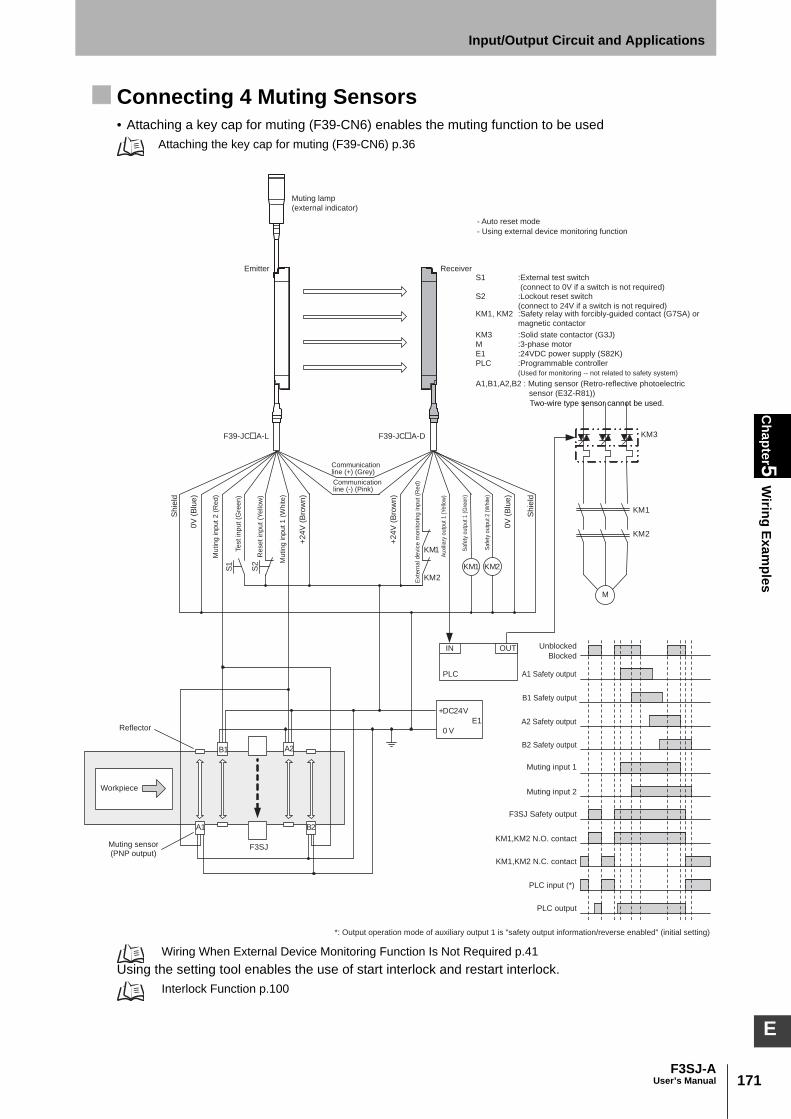
171F3SJ-A
User’s Manual
Chapter5
Wiring Exam
plesInput/Output Circuit and Applications
E
Connecting 4 Muting Sensors• Attaching a key cap for muting (F39-CN6) enables the muting function to be used
Attaching the key cap for muting (F39-CN6) p.36
Wiring When External Device Monitoring Function Is Not Required p.41 Using the setting tool enables the use of start interlock and restart interlock.
Interlock Function p.100
F3SJ
Workpiece
KM1
KM2
S1
S2
M
KM1
KM2
OUT
PLC
IN
KM3
+DC24V
0 V
E1
A1
B1 A2
B2
KM1 KM2
*: Output operation mode of auxiliary output 1 is "safety output information/reverse enabled" (initial setting)
F39-JC A-L F39-JC A-D
Emitter Receiver
- Auto reset mode
- Using external device monitoring function
Muting lamp
(external indicator)
Communicationline (+) (Grey)
Communicationline (-) (Pink)
Shie
ld
0V
(B
lue)
Muting input 2 (
Red)
Test in
put (G
reen)
Reset
input
(Yello
w)
Muting input 1 (
White)
+24V
(B
row
n)
+24V
(B
row
n)
Exte
rna
l d
evic
e m
on
ito
rin
g in
pu
t (R
ed
)
Au
xilia
ry o
utp
ut
1 (
Ye
llow
)
Safe
ty o
utp
ut
1 (
Gre
en
)
Safe
ty o
utp
ut
2 (
Wh
ite)
0V
(B
lue)
Shie
ld
S1 :External test switch
(connect to 0V if a switch is not required)S2 :Lockout reset switch
(connect to 24V if a switch is not required)KM1, KM2 :Safety relay with forcibly-guided contact (G7SA) or
magnetic contactor
KM3 :Solid state contactor (G3J)
M :3-phase motor
E1 :24VDC power supply (S82K)
PLC :Programmable controller
(Used for monitoring -- not related to safety system)
A1,B1,A2,B2 : Muting sensor (Retro-reflective photoelectric
sensor (E3Z-R81))
Unblocked
Blocked
Muting input 1
Muting input 2
F3SJ Safety output
A1 Safety output
B1 Safety output
A2 Safety output
B2 Safety output
KM1,KM2 N.O. contact
KM1,KM2 N.C. contact
PLC input (*)
PLC output
(PNP output)
Reflector
Muting sensor
Two-wire type sensor cannot be used.
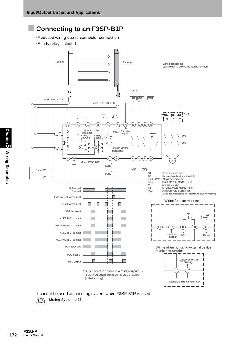
172
Chapter5
Wiring Exam
ples
F3SJ-AUser’s Manual
Input/Output Circuit and Applications
Connecting to an F3SP-B1P•Reduced wiring due to connector connection•Safety relay included
It cannot be used as a muting system when F3SP-B1P is used. Muting System p.35
PLC
IN1 IN2 OUT
S1S
2
A1 H1 L1 J1 H1 X1 P1 13 23 33 41
KM3
KM1
KM2
K1
K2
K1 K2
A2 PE T31 T32 14 24 34 42
KM1 KM2KM1
KM2E1
+DC24V
0V
M
Emitter Receiver
Interlockselection
TestReset Auxiliary
output
External device monitoring
Model F3SP-B1P
- Manual reset mode
- Using external device monitoring function
S1 :External test switch
S2 :Interlock/lockout reset switch
KM1, KM2 :Magnetic contactor
KM3 :Solid state contactor (G3J)
M :3-phase motor
E1 :24VDC power supply (S82K)
PLC :Programmable controller
(Used for monitoring not related to safety system)
Model F39-JC B-L
Model F39-JC B-D
Unblocked
Blocked
External test switch (S1)
Reset switch (S2)
Safety output
K1,K2 N.O. contact
KM1,KM2 N.O. contact
K1,K2 N.C. contact
KM1,KM2 N.C. contact
PLC input 1(*)
PLC input 2
PLC output
* Output operation mode of auxiliary output 1 is
"safety output information/reverse enabled"
(initial setting)
Safety output 1
Safetyoutput 2
S2
X1H1J1L1H1
S1
Wiring for auto reset mode
ResetTestInterlockselection
T32T31
Wiring when not using external device monitoring function
External device monitoring
Standard short-circuit bar

173F3SJ-A
User’s Manual
Chapter5
Wiring Exam
plesInput/Output Circuit and Applications
E
Connecting to an F3SX-E-L2R2•Emergency stop switch can be connected •Door switch, two hand control, single beam, or relay unit can be used in combination with F3SX•Various settings can be changed and input/output terminals can be monitored using the setting
support software for F3SX
S1
S211
12 22
21
DC24V
E1
A1 T11 T12 T21 T22 Y1 Y2 Y3
DC24V
E1
A2
DC24V
DC24V
COM
0V
SSC AS3 AS2 AS1 SS1 SS2 FB
E1
DC24VRY1 RY2
DC24V
E1
KM1
KM2
M
RY1
RY2
15 10121314169 11
2 754318 6
12 3424
3311 23
AC
K1
K2
KM1 KM2
2 754318 6
15 10121314169 11
Wiring when safety light curtain
F3SJ is not used
L2 Module
Emitter Receiver
F3SJ (1st unit)
Communicationline (+) (Grey)
Communicationline (-) (Pink)
Sh
iel
0V
(B
lue
)
Op
en
Te
st
inp
ut
(Gre
en
)
Re
se
t in
pu
t (Y
ello
w)
Inte
rlock
sele
ctio
n in
put (W
hite
)
+2
4V
(B
row
n)
+2
4V
(B
row
n)
Exte
rna
l d
evic
e m
on
ito
rin
gin
pu
t (R
ed
) (N
ote
2)
Au
xilia
ry o
utp
ut 1
(Y
ello
w)
(No
te 2
)
Au
xili
ary
ou
tpu
t 2
(R
ed
)
Sa
fety
ou
tpu
t 1
(G
ree
n)
Sa
fety
ou
tpu
t 2
(W
hite
)
0V
(B
lue
)
Sh
ield
Main Module
Control Circuit
Motor controller(operation command)
S1 :Emergency stop switch
(direct circuit operation contact)(A165E, A22E)
S2 :Reset switch
KM1, KM2 :Magnetic contactor
RY1, RY2 :Relay
M :3-phase motor
E1 :24VDC power supply (S82K)Sh
ield
0V
(B
lue
)
DC
24
V (
Bro
wn
)
DC
24
V (
Bro
wn
)
0V
(B
lue
)
Sh
ield
Te
st
inp
ut
(Gre
en
)
Re
se
t in
pu
t (Y
ello
w)
Inte
rlo
ck s
ele
ctio
n in
pu
t (W
hite
)
Op
en
Exte
rna
l d
evic
e m
on
ito
rin
gin
pu
t (R
ed
) (N
ote
2)
Au
xili
ary
ou
tpu
t 1
(Y
ello
w)(
No
te 2
)
Au
xili
ary
ou
tpu
t 2
(R
ed
)
Safe
ty o
utp
ut
1 (
Gre
en
)
Safe
ty o
utp
ut
2 (
Wh
ite
)
Communicationline (+) (Grey)
Communicationline (-) (Pink)
F3SJ (2nd unit)Emitter Receiver
Sh
ield
Test SW
0V
(B
lue
)
Op
en
(R
ed
)
Te
st
inp
ut
(Gre
en
)
Re
se
t in
pu
t (Y
ello
w)
Inte
rlock
sele
ctio
n in
put (W
hite
)
DC
24
V (
Bro
wn
)
Wiring when F3SJ's testing function is used
Relay Output Module
(R2 Module)
Fuse
- F3SJ settings
- Auto reset mode
- Does not use external device monitoring function
- F3SX-E-L2R settings
- Manual reset mode
- Using feedback time monitoring function
Model F39-JC A-Lcable for emitter
Model F39-JC A-D cable for receiver
Model F39-JC A-L cable for emitter
Model F39-JC A-D cable for receiver
Y3Y2Y1
E1
DC24V
S2
Wiring for auto reset mode
Note 1 :The OFF-delay contacts (K1, K2) may instantly turns OFF due to a
circuit error occurring in the controller. Accordingly, when the
current supply to the motor is ceased before the motor stops and it
may cause a hazardous situation to the system, the example of
wiring above should correspond to the Category 2. If, however, it
may not cause a hazardous situation, the example of wiring above
should correspond to the Category 4.
Note 2 :Example when the auxiliary output is of standard setting (ON when
light interrupted).
For other than standard setting, refer to the Catalog or User's
Manual of F3SN-A/F3SH/F3SJ.
Note 3 :When the F3SJ is series-connected, or 5 or more sets are
connected to the total system of F3SX, power
must be supplied to F3SJ from external source. For details, see
documentation of F3SX.
Note 4 :Example of circuit above corresponds to the Stop Category
(EN60204-1) 1.
Note 5 :In the example of wiring above, it is necessary to change the
threshold value of feedback monitoring time in consideration for
the delay time setting value by using the function set-up software
for model F3SX (Model F3SX-CD���, sold separately).

174
Chapter5
Wiring Exam
ples
F3SJ-AUser’s Manual
Input/Output Circuit and Applications
•Using a branch connectorConnector connection is possible using a cable with connectors on both ends and branch connectorfor safety light curtains.
Wiring with a F39-JCA single-end connector cable enables use as a muting system.
F3SX
Cable with connectors on both ends:
F39-JC B-L (grey)Cable with connectors on both ends
F39-JC B-D (black)
Cable with connectors on both ends
F39-JC T for connecting to
branch connector
Grey Black
Branch connector for
safety light curtains
F39-CN5
F3SJ
ReceiverF3SJ
Emitter

175F3SJ-A
User’s Manual
Chapter5
Wiring Exam
plesInput/Output Circuit and Applications
E
Connecting to a G9SA-301
S4
S1
IN1 IN2 OUT
PLC
KM3
M
KM1
KM2E1
+DC24V
0V
A1 A2 T11 T12
S2
KM1
KM2
T31
K1
34
K2
1
ab
25
T32 41332313
123456
JP
6
a
b
K1 K2
K1
K2
PE T21 T23 T22 A B 14 24 34 42
Control Circuit
KM1 KM2
*1
11
12
21
22
S3
Emitter Receiver
Sh
ield
0V
(B
lue
)
Op
en
Test in
put (G
reen)
Reset in
put (Y
ello
w)
Inte
rlock s
ele
ction input (W
hite)
+2
4V
(B
row
n)
Communicationline (+) (Grey)
Communicationline (-) (Pink)
+2
4V
(B
row
n)
Ext
ern
al d
eva
ce m
on
itorin
g in
pu
t (R
ed
)
Auxili
ary
outp
ut 1
(Yello
w)
Safe
ty o
utp
ut 1 (
Gre
en)
Safe
ty outp
ut 2 (
White
)
0V
(B
lue
)
Sh
ield
Model G9SA-301
Unblocked
Blocked
External test switch
(S1)
Interlock reset switch
(S2)
Emergency stop switch
(S3)
Control output
K1,K2 N.O. contact
KM1,KM2 N.O. contact
K1,K2 N.C. contact
KM1,KM2 N.C. contact
PLC input 1(*)
PLC input 2
PLC output
S1 :External test switch
(connect to 0V if a switch is not required)
S2 :Interlock reset switch
S4 :Lockout reset switch
(connect to 24V if a switch is not required)
KM1, KM2 :Magnetic contactor
KM3 :Solid state contactor (G3J)
M :3-phase motor
E1 :24VDC power supply (S82K)
PLC :Programmable controller
(Used for monitoring -- not related to safety system)
- F3SJ settings
- Auto reset mode
- Does not use external device monitoring function
- G9SA-301 settings
- Manual reset mode
- Using feedback loop
- Using emergency stop switch
*1 If an emergency stop switch is not used, connect safety
output 1 to T12 terminal and safety output 2 to T23 directly.
S3 : Emergency stop switch (forcibly-opening contact)
(A165E, A22E)
Model F39-JC A-L Model F39-JC A-D
Au
xili
ary
ou
tpu
t 2
(R
ed
)
* Output operation mode of auxiliary output 1 is "safety output information/reverse enabled" (initial setting)
T32T31
KM1
KM2
K1
K2
Control
Circuit
A B
Wiring for auto reset mode

176
Chapter5
Wiring Exam
ples
F3SJ-AUser’s Manual
Input/Output Circuit and Applications
Connecting to a G9SA-300-SC •Reduced wiring due to connector connection
F
KM1
KM2
14 24 34 M
K3 K1 K3 K2K1
K2
K3
K1 K2 K3K3
E2E1D2D1C1
GND
Vcc
S1
+DC24V
0 VE1
KM1
KM2
S2
Vcc J1 A1 A2 T11 T12 H1 Y1 X1 13 23 33
GND G1 T21 T22
KM1 KM2
ReceiverEmitter
Test
ReceiverEmitter
(Note 2)
Safety output Safety output
Master select
Model G9SA-300-SC
KM1,KM2 N.C. contact
UnblockedBlocked
Interlock reset switch
(S1)
Safety output 1, 2
K1,K2 N.O. cotact
KM1,KM2 N.O. cotact
K1,K2 N.C. contact
External test switch
(S2)
K3 N.O. cotact
K3 N.C. contact
S1 :Interlock reset switch
S2 :External test switch
(open between Vcc and J1 if a switch is not required)
KM1, KM2 :Magnetic contactor
M :3-phase motor
E1 :24V DC power supply (S82K)
Note 1) F3SJ's external device monitoring and auxiliary output cannot be used.
Note 2) S2 performs normal operation when opened and external test when short-circuited.
Note 3) Do not connect any cable to terminals C1, D1, D2, E1, and E2
Model F39-JC C-L Model F39-JC C-D
Sync2-
Sync2+
Sync2-
Sync2+
- F3SJ settings - Auto reset mode - Not using external device monitoring- G9SA-300-SC settings - Manual reset mode - Using feedback loop
Wiring for auto reset mode
X1Y1T11 T12 H1
KM1
KM2

177F3SJ-A
User’s Manual
Chapter5
Wiring Exam
plesInput/Output Circuit and Applications
E
Connecting to a G9SB-301-D •Thin (22.5mm thick)
Use G9SB-301-B for 3a+1b contact auto reset type.Use G9SB-200-D for 2a contact manual reset type, or G9SB-200-B for 2a contact auto reset type. For details, see thecatalogs.
OUT
PLC
KM1
KM2
IN1 IN2
KM3
A1
14 24 34 42
41332313T32T31T11A2
G9SB-301-D
KM1
KM2
T12
K1
K1
K2
K1
S2
S1
a K2
ControlCircuit
a
T21 T22
K2
K2 K1
F39-JC A-L F39-JC A-D
TH
SA
+DC24V
0V
E1
*1*1
*1*1
M
*212
21
22
S3
KM1 KM2
Emitter ReceiverS
hie
ld
0V
(B
lue
)
Op
en T
est in
put (G
reen)
Reset in
put (Y
ello
w)
Inte
rlock s
ele
ction input (W
hite)
+2
4V
(B
row
n)
Communication line (+) (Grey)
Communicationline (-) (Pink)
+2
4V
(B
row
n)
Ext
erna
l dev
ace
mon
itorin
g in
put (
Red
)
Auxi
liary
outp
ut 1 (
Yello
w)
Safe
ty o
utp
ut 1 (
Gre
en)
Safe
ty outp
ut 2 (
White
)
0V
(B
lue
)
Sh
ield
Unblocked
Blocked
External test switch
(S1)
Interlock reset switch
(S2)
Emergency stop switch
(S3)
Safety output1, 2
K1,K2 N.O. contact
KM1,KM2 N.O. contact
K1,K2 N.C. contact
KM1,KM2 N.C. contact
PLC input 1(*)
PLC input 2
PLC output
S1 :External test switch (connect to 0V if a switch is not required)
S2 :Interlock reset switch
S4 :Lockout reset switch (connect to 24V if a switch is not required)
KM1, KM2 :Magnetic contactor
KM3 :Solid state contactor (G3J)
M :3-phase motor
E1 :24VDC power supply (S82K)
PLC :Programmable controller
(Used for monitoring -- not related to safety system)
- F3SJ settings
- Auto reset mode
- Does not use external device monitoring function
- G9SB-301-D settings
- Manual reset mode
- Using feedback loop
*1 The G9SB-200-D (17.5 mm thick), with no 33-34 and 41-42, is also available.
S3 : Emergency stop switch (forcibly-opening contact)
(A165E, A22E)
*2 If an emergency stop switch is not used, connect safety output 1 to T12
terminal and safety output 2 to T22 directly.
S4
Auxili
ary
outp
ut
2 (
Red)
* Output operation mode of auxiliary output 1 is "safety output information/reverse enabled" (initial setting)
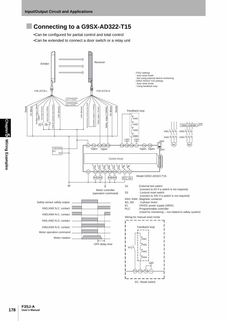
178
Chapter5
Wiring Exam
ples
F3SJ-AUser’s Manual
Input/Output Circuit and Applications
Connecting to a G9SX-AD322-T15•Can be configured for partial control and total control •Can be extended to connect a door switch or a relay unit
A1
A2 S14 S24
KM1 KM2
S34 S44 S54
KM3 KM4
L1 X1 X2
T11
KM1
KM2
KM3
KM4
+24V +24V
T12 T21 T22 T31 T32 T33 Y1 T41 T42 M1 M2
PLC, etc.
Motor controller
OFF
AND
KM1
KM2
KM3
S34
KM4
Control circuit
S1
S2
F39-JC A-L F39-JC A-D
+DC24V
0VE1
Feedback loop
- F3SJ settings - Auto reset mode - Not using external device monitoring- G9SX-AD322-T15 settings - Auto reset mode - Using feedback loop
EmitterReceiver
Motor controller
(operation command)
Model G9SX-AD322-T15
Open Open Open Open
Safety sensor safety output
KM1,KM2 N.C. contact
KM3,KM4 N.C. contact
KM1,KM2 N.O. contact
KM3,KM4 N.O. contact
Motor operation command
Motor rotation
OFF-delay time
Sh
ield
0V
(B
lue
)
Op
en
Test in
put (G
reen)
Reset in
put (Y
ello
w)
Inte
rlock s
ele
ction input (W
hite)
+2
4V
(B
row
n)
Communicationline (+) (Grey)
Communicationline (-) (Pink)
+2
4V
(B
row
n)
Ext
ern
al d
eva
ce m
on
itorin
g in
pu
t (R
ed
)
Au
xili
ary
ou
tpu
t 1
(Y
ello
w)
Sa
fety
ou
tpu
t 1
(G
ree
n)
Safe
ty outp
ut 2 (
White
)
0V
(B
lue
)
Sh
ield
S1 :External test switch
(connect to 0V if a switch is not required)
S2 : Lockout reset switch
(connect to 24V if a switch is not required)
KM1~KM4 :Magnetic contactor
M1, M2 : 3-phase motor
E1 :24VDC power supply (S82K)
PLC :Programmable controller
(Used for monitoring -- not related to safety system)
Auxili
ary
outp
ut
2 (
Red)
+24V
T32 T33 Y1
KM3
KM4
T31
KM1
KM2
S3
Wiring for manual reset mode
Feedback loop
S3 : Reset switch
Chapter6
Checklists
179F3SJ-A
User’s Manual
E
Chapter6 Checklists
Pre-Operation Checklists 180
Maintenance Checklists 183

180
Chapter6
Pre-Operation C
hecklists
F3SJ-AUser’s Manual
Checklists
Pre-Operation Checklists
Make sure to test the operation of the F3SJ after installation to verify that the F3SJ operates as intended. Make sure to stop the machine until the test is complete. Unintended function settings may cause a person to go undetected, resulting in serious injury.
After installation, the highest level administrator must use the following checklist to verify the operation,placing a check mark in each of the boxes.
Checklists Installation Condition Check The machine itself does not prevent the operation of safety functions such as stopping. The hazardous part of a machine cannot be reached without passing through the detection zone of
the F3SJ.The system is configured so that the F3SJ can always detect a worker who is working in the
hazardous zone. The interlock reset switch is installed in a location that provides a clear view of the entire hazardous
zone and it cannot be activated from within the hazardous zone. Safety distance has been calculated. Calculated distance: S = ( )mmSafety distance has been calculated with larger detection capability when floating blanking is used.
Calculated distance: S = ( )mmThe actual distance is equal to or greater than the calculated distance. Actual distance = ( )mmReflective surfaces are not installed in prohibited zones.Not installed in a reflective configuration.When muting function is used, a muting sensor must be installed so that muting state should not occur
when a human body enters a detection zone of F3SJ by mistake.When muting function is used, a muting sensor must be installed so that muting state should not occur
when a human body enters a hazardous zone of a machine.When muting function is used, muting state can be checked from where a worker operates or adjust
the machine.A muting sensor consists of 2 independent devices.It is not used in flammable or explosive atmosphere.
Wiring Check Before Power Is Turned ON Power supply unit must be dedicated to F3SJ and other devices for electrical-detection protective
function of F3SJ such as safety controller and muting sensor, and must not be connected to otherdevices. It must have tolerance against total rated current of devices if it is connected to multipledevices.
The power supply unit is a 24 VDC unit that conforms to the EMC Directive, Low-voltage Directive,and output holding specifications.
The power supply polarity is not connected in reverse. Emitter/receiver cables are properly connected to the respective emitters/receivers. Double insulation is used between I/O lines and the hazard potential (commercial power supplies,
etc.).Outputs are not short-circuited to +24V line. Loads are not connected to the +24V line. All lines are not connected to commercial power source. F3SJ's power supply connector and series connection connector must not be attached upside down.Model of emitter and receiver must be the same.When 2 or more sets of F3SJ are used, series connection is made or mutual interference prevention
measures are taken. When 2 or more sets of F3SJs are used in series connection, PNP output type and NPN output type
must not be connected.

181F3SJ-A
User’s Manual
Chapter6
Pre-Operation C
hecklistsChecklists
E
A secondary sensor farthest from its power supply has either of the followings:- Cap- Key cap for muting - Muting lamp (set of lamp and cable)
Neither connector, cap, or bracket must be loose.Auxiliary outputs 1 and 2, and external indicator outputs 1 and 2 must not be used as safety output.Power supply's 0V must be grounded.Wiring must not be bent, cracked, nor damaged.
Operation Check While the Machine Is StoppedThe test rod is not deformed.
Depending on the unit's model and settings of floating blanking function, detection capability mayvary. Use a test rod with an appropriate diameter for inspection. Use a test rod with an appropriatediameter for inspection, since F3SJ-AP55 has not accessory test rod.Accessory test rodcannot be used because of the diameter when floating blanking function is used. Use a test rod withan appropriate diameter.
The sensor can detect a test rod wherever it is in the detection zone. In other words, when a test rodis inserted into the detection zone, all 5 incident light level indicators turn OFF, and the OFF-stateindicator turns ON. When fixed blanking function is used, you must ensure that all blanked zones in the detection zoneare covered by construction and that there should be no zone that cannot detect the test rod in thedetection zone.To check detection, move the test rod as shown in the diagram below.
When the external test function is used: The OFF-state indicator turns ON when the test input line is short-circuited to 9 to 24V.
When the external device monitoring function is used: When the F3SJ is blocked and the external device monitoring input terminal is open, it enters alockout state.
When the start interlock function is used: After the F3SJ is turned ON, the OFF-state indicator remains turned ON, even if the F3SJ is receivinglight. The reset switch input turns ON the ON-state indicator.
When the restart interlock function is used: While the ON-state indicator is ON, the OFF-state indicator remains turned ON, even when the F3SJis blocked and then receives light again. The reset switch input turns ON the ON-state indicator.
When muting function is used, minimum muting time limit required must be set.When muting function's operation mode is exit only muting mode, minimum muting waiting time
required must be set.Under muting state, a signal that indicates muting state must be output from either of the followings:
- External Indicator 1 or 2 - Auxiliary Output 1
When override function is used, minimum override time limit required must be set.
Start
Stop

182
Chapter6
Pre-Operation C
hecklists
F3SJ-AUser’s Manual
Checklists
Under override state, a signal that indicates override state must be output from either of the followings: - External Indicator 1 or 2 - Auxiliary Output 1
Checking that Hazardous Parts Stop While the Machine Operates The hazardous parts stop immediately when a test rod is inserted into the detection zone at 3
positions: "directly in front of the emitter", "directly in front of the receiver", and "between the emitterand receiver". (Use the appropriate test rod.)
The hazardous parts remain stopped as long as the test rod is in the detection zone. The hazardous parts stop when the power of the F3SJ is turned OFF. The actual response time of the whole machine is equal to or less than the calculated value.

183F3SJ-A
User’s Manual
Chapter6
Maintenance C
hecklistsChecklists
E
Maintenance Checklists
Perform daily and 6-month inspection for the F3SJ. Otherwise, the system may fail to work properly, resulting in serious injury.
Do not try to disassemble, repair, or modify this product. Doing so may cause the safety functions to stop working properly.
To ensure safety, keep a record of the inspection results. When the user is a different person from those who installed or designed the system, he/she must be properlytrained for maintenance.
Checklists Inspection at Startup and When Changing Operators There is no approach route other than through the detection zone of the F3SJ. Part of the operator's body always remains in the detection zone of the F3SJ when working around
the machine's hazardous part. The actual safety distance is equal to or greater than the calculated value. There must be no dirt on or damage to the optical surface, spatter protection cover (F39-HJ, sold
separately), or environment-resistant casing (F39-EJ, sold separately) of the F3SJ.OFF output indicator must be turned ON when test input line is short-circuited to 9 to 24V.When muting function is used, muting lamp must not be clear due to dirt or degradation.The test rod is not deformed. When the start interlock function is used:
After the F3SJ is turned ON, the OFF output indicator must remain turned ON, even if the F3SJ isreceiving light. The reset switch input must turn ON the ON output indicator.
When the restart interlock function is used:While the ON output indicator is ON, the OFF output indicator must remain turned ON, even whenthe F3SJ is blocked and then receives light again. The reset switch input must turn ON the ON outputindicator.
When the power of the F3SJ is turned ON while nothing is in the detection zone, it must operate asfollows:If start interlock is not used: Power indicator and ON output indicator must turn ON within 2 seconds(2.2 seconds in case of series connection).If start interlock is used: Power indicator and OFF output indicator must turn ON within 2 seconds (2.2seconds in case of series connection).
Nothing should exist in the detection zone and 5 incident light level indicators must turn ON at power on.

184
Chapter6
Maintenance C
hecklists
F3SJ-AUser’s Manual
Checklists
The test rod is detected when it is moved around in the detection zone as shown in the diagram below. In other words, when a test rod is inserted into the detection zone, all 5 incident light level indicatorsturn OFF, and the OFF output indicator turns ON. Use an appropriate test rod based on the type code and floating blanking function for inspection.
Confirm that hazardous parts should stop while the machine is operating, as shown below.When muting function is used, installation condition of muting sensor must not be changed.When muting function is used, muting status can be checked from where a worker operates or adjust
the machine.Neither connector, cap, or bracket must be loose.
Checking that Hazardous Parts Stop While the Machine Operates The hazardous parts are movable when nothing is in the detection zone. The hazardous parts stop immediately when a test rod is inserted into the detection zone at 3
positions: "directly in front of the emitter", "directly in front of the receiver", and "between the emitterand receiver". (Use the appropriate test rod.)
The hazardous parts remain stopped as long as the test rod is in the detection zone. The hazardous parts stop when the power of the F3SJ is turned OFF while nothing is in the detection
zone.
Items to Inspect Every 6 Months or When Machine Settings Are Changed In addition to inspection item at operation start, following items must also be verified.The outputs of the F3SJ and the machine are properly wired. The total number of times that the control relays/contactors have switched is significantly lower than
their design lives.There is no disturbance light.Safety distance has been calculated with changed detection capability when floating blanking is
changed.Calculated distance: S = ( )mm
When muting function setting is changed, a muting sensor must be installed so that muting stateshould not occur when a human body enters a detection zone of F3SJ by mistake.
When muting function setting is changed, a muting sensor must be installed so that muting stateshould not occur when a human body enters a hazardous zone of a machine.
When muting function setting is changed, a muting sensor must consist of 2 independent devices.When F3SJ is connected again, a secondary sensor farthest from its power supply has either of the
followings:- Cap- Key cap for muting - Muting lamp (set of lamp and cable)
Power supply's 0V must be grounded.Wiring must not be bent, cracked, nor damaged.
Start
Stop
Chapter7
Appendix
185F3SJ-A
User’s Manual
E
Chapter7 Appendix
Troubleshooting 186
Accessories (Sold Separately) 195
Glossary 203
Related Standards 207
Revision History 209
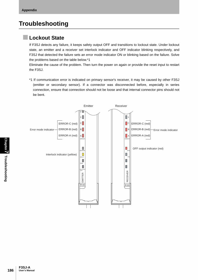
186
Chapter7
Troubleshooting
F3SJ-AUser’s Manual
Appendix
Troubleshooting
Lockout StateIf F3SJ detects any failure, it keeps safety output OFF and transitions to lockout state. Under lockoutstate, an emitter and a receiver set interlock indicator and OFF indicator blinking respectively, andF3SJ that detected the failure sets an error mode indicator ON or blinking based on the failure. Solvethe problems based on the table below.*1Eliminate the cause of the problem. Then turn the power on again or provide the reset input to restartthe F3SJ.
*1 If communication error is indicated on primary sensor's receiver, it may be caused by other F3SJ(emitter or secondary sensor). If a connector was disconnected before, especially in seriesconnection, ensure that connection should not be loose and that internal connector pins should notbe bent.
ERROR ERROR
A
B
C
A
B
C
POWER
INTLK
EDM
BLANKING
ON
OFF
1
2
1
30 30
ERROR-C (red)
ERROR-B (red)
ERROR-A (red)
ERROR-C (red)
ERROR-B (red)
ERROR-A (red)
EM
ITT
ER
RE
CE
IVE
RError mode indicator Error mode indicator
Interlock indicator (yellow)
OFF output indicator (red)
Emitter Receiver

187F3SJ-A
User’s Manual
Chapter7
TroubleshootingAppendix
E
Emitter Receiver Error code Error Description Cause Solution
10, 11 Mutual interference error
Disturbance light is received. Block the disturbance light. p.120
The receiver is receiving light emitted from another photoelectric switch or F3SJ.
See Chapter 4 "Mutual Interference Prevention".
p.119
19, *2 Power supply capacity error
Power supply voltage is outside the rated range.
Connect to a 24VDC± 20% power supply voltage.
Voltage fluctuation due to insufficient power supply capacity.
Replace the power supply with one that has a larger capacity.
Instantaneous break or instantaneous stop due to power sharing with other devices.
Do not share the power supply with other devices, and connect to a power supply that is dedicated to devices for electrical-detection protective functions, such as the F3SJ, safety controller, muting sensor, etc.
20 Blanking monitoring error
A fixed blanking beam other than allowable beams received light.
Adjust a position of the device so that a fixed blanking beam other than allowable beam should not receiver light. Or, configure fixed blanking setting again.
p.66
Number of interrupted beams is less than (number of floating blanking beams - number of allowable beams).
Set number of floating blanking beams and number of allowable beams based on a size of interrupting object.
p.70
30, 31, 32, 37, 39
Communication error
The communication line or other wiring is broken or short-circuited.
Check the wiring and cables.
Communication error due to noise.
Check the noise level in the environment around the communication line. The inductive noise tends to be induced especially if the signal line and the power line are arranged in parallel. Be sure to lay the power line away from the signal line.
If the wiring is extended without using the exclusive cord (F39-JC), no cord with the same performance or more than the exclusive cord is used.
Use a cord (twisted-pair cable) with the same performance or more than the exclusive cord (F39-JC). Otherwise connect the shield to the 0V line.
ON Blink OFF
A
B
C
A
B
C
A
B
C
A
B
C
A
B
C
A
B
C
A
B
C
A
B
C

188
Chapter7
Troubleshooting
F3SJ-AUser’s Manual
Appendix
A power cable or series connection cable connector is detached. If not, a contact failure due to the loose connector, the intrusion of liquid (oil etc.) into the connector, or the attachment of a foreign material has occurred.
Check connectors of power cable and series-connection cables. After cleaning the inside of the cap (if any foreign material is attached), tighten the cap more closely. Replace the cap if any liquid such as oil has intruded.
Temporary power supply voltage reduction in motion.
Check for temporary power supply voltage reduction (by about 12VDC) by the influence of the induction load etc. If the exclusive power supply is not used, check the power consumption of other connected devices for enough capacity.
Connection positions are reversed for emitter(s) and receiver(s) under series connection.
Correct connection positions of all F3SJ's emitters and receivers.
Failure of F3SJ's internal circuit. Replace the F3SJ.
The setting tool is connected to series connection that includes F3SJ of version 1.
The setting tool cannot be used if the connection includes F3SJ of version 1. Do not connect F3SJ of version 1.
38 Lockout of other sensor than the primary receiver (error mode indicator will not turn on)
A sensor other than the primary receiver is in lockout when series-connected.
Solve the problem of an emitter or F3SJ in a series connection.
3A Excessive number of beams
Total number of beams of F3SJs under series connection exceeds 400.
Rearrange series connection so that total number of beams of series connection should not exceed 400.
3B Excessive number of connected sensors
Five or more sensors are connected.
Number of F3SJs under series connection must be 4 or less.
3C Model error (between series connection)
Models of the primary sensor and secondary sensor are unavailable for connection. (Primary: PNP Output, Secondary: NPN Output, etc.)
Connect them properly. p.122
3D Model error (between emitter/receiver)
Models are different between an emitter and a receiver (lengths, output types, or beam gaps are different)
3E Sensor count error (no emitter)
Number of emitters under series connection is less than that of receivers (emitters: 3, receivers: 4, etc.)
3F Sensor count error (no receiver)
Number of receivers under series connection is less than that of receivers (emitters: 4, receivers: 3, etc.)
Emitter Receiver Error code Error Description Cause Solution
A
B
C
A
B
C
A
B
C
A
B
C

189F3SJ-A
User’s Manual
Chapter7
TroubleshootingAppendix
E
40 Setting value error Function setting value configured by the setting tool is out of valid range.
Perform setting recovery to restore factory settings.
p.109
Muting enabling keycap is attached but muting/override information is not assigned to either of auxiliary output 1, external indicator output 1 or 2.
To use muting function, muting/override information must be assigned to at least one of auxiliary output 1, external indicator output 1 or 2.
p.95
4E Cap position error Failure of F3SJ's internal circuit. Replace the F3SJ.
4F Cap error Cap is not attached. Attach the cap properly.
A contact failure due to the loose cap, the intrusion of liquid (oil etc.) into the cap, or the attachment of a foreign material has occurred.
After cleaning the inside of the cap (if any foreign material is attached), tighten the cap more closely. Replace the cap if any liquid such as oil has intruded.
50, 51, 52, 53 External device monitoring error
Relay is welded. Replace the relay.
The relay and external device monitoring input line are not properly wired.
Check the wiring for the relay.
The relay response time exceeds the allowable delay time.
Replace the relay with one that has an appropriate response time. Or, change the device monitoring time by the setting tool.
p.102
If short-circuit is made to an auxiliary output instead of a relay, the auxiliary output line is broken or short-circuited.
Make sure there is no failure in the external device monitoring input and auxiliary output lines. Or, use the setting tool to set output mode of auxiliary output 1 to safety output information and enable reverse output mode. (factory shipment setting).
p.95
Emitter(s) and receiver(s) are reversely connected when connected to connector type controller.(Connectors of F3SP-B1P's emitter/receiver are reversely attached, etc.)
Check connectors' positions.
Emitter Receiver Error code Error Description Cause Solution
A
B
C
A
B
C
A
B
C
A
B
C
A
B
C
A
B
C

190
Chapter7
Troubleshooting
F3SJ-AUser’s Manual
Appendix
5B Failure of interlock selection input line
The interlock selection input line is broken or short-circuited.
Check wiring of interlock selection input line.
5E Interlock wiring error
The reset input line and interlock selection input line are not properly wired.
Check that wiring has been made for auto reset or manual reset.
p.27, p.28
Connection positions are reversed for emitter(s) and receiver(s).
Correct connection positions and directions of all F3SJs.
p.124Connection direction is upside down for emitter(s).
Emitter(s) and receiver(s) are reversely connected when connected to connector type controller.(Connectors of F3SP-B1P's emitter/receiver are reversely attached, etc.)
Check connectors' positions.
A contact failure due to the loose connector, the intrusion of liquid (oil etc.) into the connector, or the attachment of a foreign material has occurred.
After cleaning the inside of the connector (if any foreign material is attached), tighten the connector more closely.
5D Muting wiring error
The reset input line is not properly wired when muting enabling keycap is attached.
Wire the reset input line properly. p.40
60, 61, 62, 63, 64, 65
Safety output error (1)
Safety output lines are short-circuited to each other at power on.
Wire the output lines properly.Check the control output is in contact with other lines at the device or the connection.Safety output line and 24V, 0V, or
other input/output line are short-circuited at power on.
Temporary power supply voltage reduction in motion.
Check for temporary power supply voltage reduction (by about 12VDC) by the influence of the induction load etc. If the exclusive power supply is not used, check the power consumption of other connected devices for enough capacity.
Emitter Receiver Error code Error Description Cause Solution
A
B
C
A
B
C
A
B
C
A
B
C
A
B
C
A
B
C

191F3SJ-A
User’s Manual
Chapter7
TroubleshootingAppendix
E
Effect of noise is excessive. If other devices using the same power supply generate noise, do not share the same power supply with other devices and use it as that exclusive for the safety component.
The inductive noise tends to be induced especially if the power line and the power supply line are arranged in parallel. Arrange the exclusive power supply near the light curtain or lay the power line away from the power line.
If the power supply for operation is located near the power supply and it uses the same ground, it is subject to the influence of common mode noise from the ground. Separate the grounding point or use it as the exclusive ground.
Failure of safety output circuit. Replace the receiver.
Connection positions are reversed for emitter(s) and receiver(s), or their directions are upside down.
Correct connection positions and directions of all F3SJs.
p.124
Series connection cable error (1)
Safety output error occurred due to short circuit, breakage, or disconnection of series connection cables.
Check if series connection cables are connected properly. Replace a series connection cable if it is broken.
66, 67, 68, 69 Safety output error (2)
Safety output lines are short-circuited to each other after power on.
Wire the output lines properly.Check the control output is in contact with other lines at the device or the connection.Safety output line and 24V, 0V, or
other input/output line are short-circuited after power on.
Series connection cable error (2)
Safety output error occurred due to short circuit, breakage, or disconnection of series connection cables.
Check if series connection cables are connected properly. Replace a series connection cable if it is broken.
70 External indicatoroutput error
The external indicator output and 24V, 0V, or other input/output line are short-circuited when diagnosis function of an external indicator output is being enabled. Or, an external indicator output line is broken.
Perform the proper wiring.
Load (such as indicator or relay) connected to an external indicator output is broken.
Replace the load.
Failure of external indicator circuit.
Replace the F3SJ.
Emitter Receiver Error code Error Description Cause Solution
A
B
C
A
B
C
A
B
C
A
B
C

192
Chapter7
Troubleshooting
F3SJ-AUser’s Manual
Appendix
*2 When an error occurred, a supply voltage error may be recorded in addition to the original errorcode if supply voltage is out of specification range.
71 Auxiliary output 1 error
The auxiliary output line and 24V, 0V, or other input/output line than external device monitoring input line are short-circuited when diagnosis function of an auxiliary output 1 is being enabled. Or, an auxiliary output line is broken.
Perform the proper wiring for auxiliary output 1.
Load (such as indicator or relay) connected to an auxiliary output 1 is broken.
Replace the load.
Failure of auxiliary output 1 circuit. Replace the F3SJ.
80 Series connection cable error (3)
Series connection cable is broken.(Test input line of a series connection cable is broken)
Replace the series connection cable.
A contact failure due to the loose connector, the intrusion of liquid (oil etc.) into the connector, or the attachment of a foreign material has occurred.
After cleaning the inside of the connector (if any foreign material is attached), tighten the connector more closely.
Error code other than those above
Effect of noise. Effect of noise is excessive. If other devices using the same power supply generate noise, do not share the same power supply with other devices and use it as that exclusive for the safety component.
The inductive noise tends to be induced especially if the power line and the power supply line are arranged in parallel. Arrange the exclusive power supply near the light curtain or lay the power line away from the power line.
If the power supply for operation is located near the power supply and it uses the same ground, it is subject to the influence of common mode noise from the ground. Separate the grounding point or use it as the exclusive ground.
Lockout of other F3SJ in the series connection
Failure occurred in another F3SJ under series connection.
Solve the problem of F3SJ in a series connection.
Failure of F3SJ's internal circuit.
F3SJ's internal circuit is damaged. Replace the F3SJ.
Emitter Receiver Error code Error Description Cause Solution
A
B
C
A
B
C
A
B
C
A
B
C
A
B
C
A
B
C
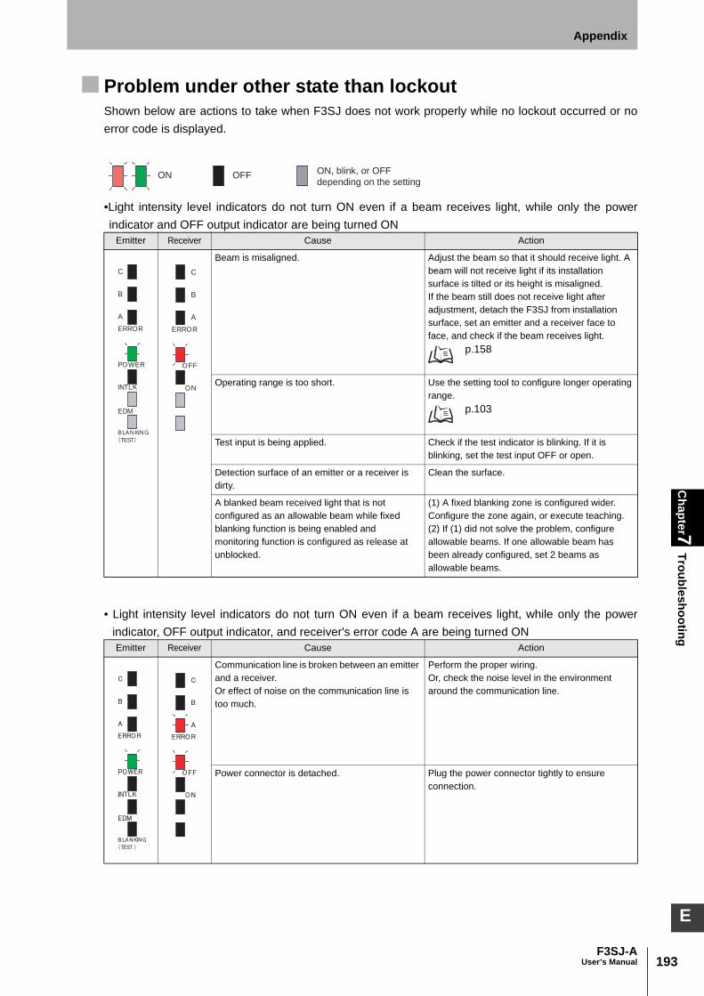
193F3SJ-A
User’s Manual
Chapter7
TroubleshootingAppendix
E
Problem under other state than lockoutShown below are actions to take when F3SJ does not work properly while no lockout occurred or noerror code is displayed.
•Light intensity level indicators do not turn ON even if a beam receives light, while only the powerindicator and OFF output indicator are being turned ON
• Light intensity level indicators do not turn ON even if a beam receives light, while only the powerindicator, OFF output indicator, and receiver's error code A are being turned ON
Emitter Receiver Cause Action
Beam is misaligned. Adjust the beam so that it should receive light. A beam will not receive light if its installation surface is tilted or its height is misaligned.If the beam still does not receive light after adjustment, detach the F3SJ from installation surface, set an emitter and a receiver face to face, and check if the beam receives light.
p.158
Operating range is too short. Use the setting tool to configure longer operating range.
p.103
Test input is being applied. Check if the test indicator is blinking. If it is blinking, set the test input OFF or open.
Detection surface of an emitter or a receiver is dirty.
Clean the surface.
A blanked beam received light that is not configured as an allowable beam while fixed blanking function is being enabled and monitoring function is configured as release at unblocked.
(1) A fixed blanking zone is configured wider. Configure the zone again, or execute teaching.(2) If (1) did not solve the problem, configure allowable beams. If one allowable beam has been already configured, set 2 beams as allowable beams.
Emitter Receiver Cause Action
Communication line is broken between an emitter and a receiver. Or effect of noise on the communication line is too much.
Perform the proper wiring.Or, check the noise level in the environment around the communication line.
Power connector is detached. Plug the power connector tightly to ensure connection.
ON OFF ON, blink, or OFF
depending on the setting
POWER
INTLK
EDM
BLANKING
TEST
ERROR
A
B
C
OFF
ON
ERROR
A
B
C

194
Chapter7
Troubleshooting
F3SJ-AUser’s Manual
Appendix
•Safety output may be turned OFF even if a beam is not blocked.Cause Action
Beam may be misaligned due to oscillation. Install F3SJ sop that it should not be affected by oscillation. Also, adjust F3SJ beams based on "Adjustment Procedure p.158 ".
Light emitted from another F3SJ or photoelectric sensor is being received.
Solve the problems based on "Mutual Interference Prevention p.119 ".
A blanked beam received light that is not configured as an allowable beam while fixed blanking function is being enabled and monitoring function is configured as release at unblocked.
Configure an allowable beam. If one allowable beam has been already configured, set 2 beams as allowable beams.
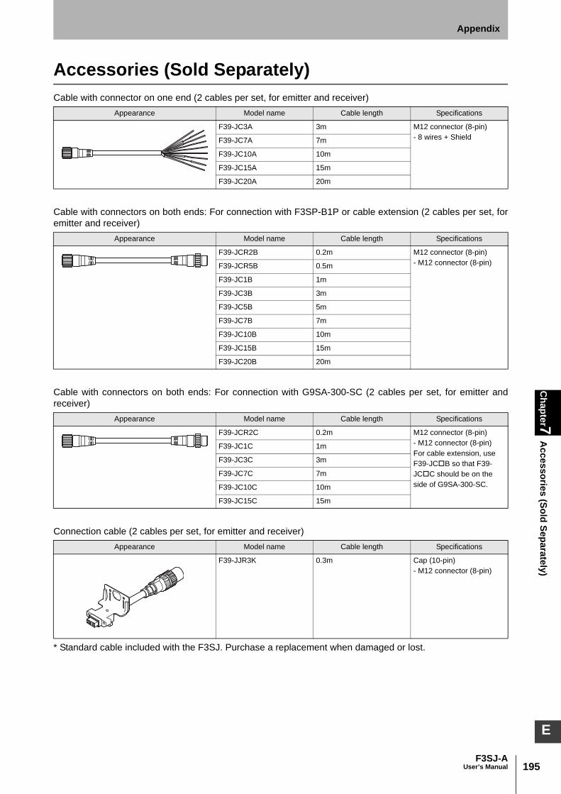
195F3SJ-A
User’s Manual
Chapter7
Accessories (Sold Separately)
Appendix
E
Accessories (Sold Separately) Cable with connector on one end (2 cables per set, for emitter and receiver)
Cable with connectors on both ends: For connection with F3SP-B1P or cable extension (2 cables per set, foremitter and receiver)
Cable with connectors on both ends: For connection with G9SA-300-SC (2 cables per set, for emitter andreceiver)
Connection cable (2 cables per set, for emitter and receiver)
* Standard cable included with the F3SJ. Purchase a replacement when damaged or lost.
Appearance Model name Cable length Specifications
F39-JC3A 3m M12 connector (8-pin) - 8 wires + ShieldF39-JC7A 7m
F39-JC10A 10m
F39-JC15A 15m
F39-JC20A 20m
Appearance Model name Cable length Specifications
F39-JCR2B 0.2m M12 connector (8-pin)- M12 connector (8-pin)F39-JCR5B 0.5m
F39-JC1B 1m
F39-JC3B 3m
F39-JC5B 5m
F39-JC7B 7m
F39-JC10B 10m
F39-JC15B 15m
F39-JC20B 20m
Appearance Model name Cable length Specifications
F39-JCR2C 0.2m M12 connector (8-pin)- M12 connector (8-pin)For cable extension, use F39-JCB so that F39-JCC should be on the side of G9SA-300-SC.
F39-JC1C 1m
F39-JC3C 3m
F39-JC7C 7m
F39-JC10C 10m
F39-JC15C 15m
Appearance Model name Cable length Specifications
F39-JJR3K 0.3m Cap (10-pin)- M12 connector (8-pin)
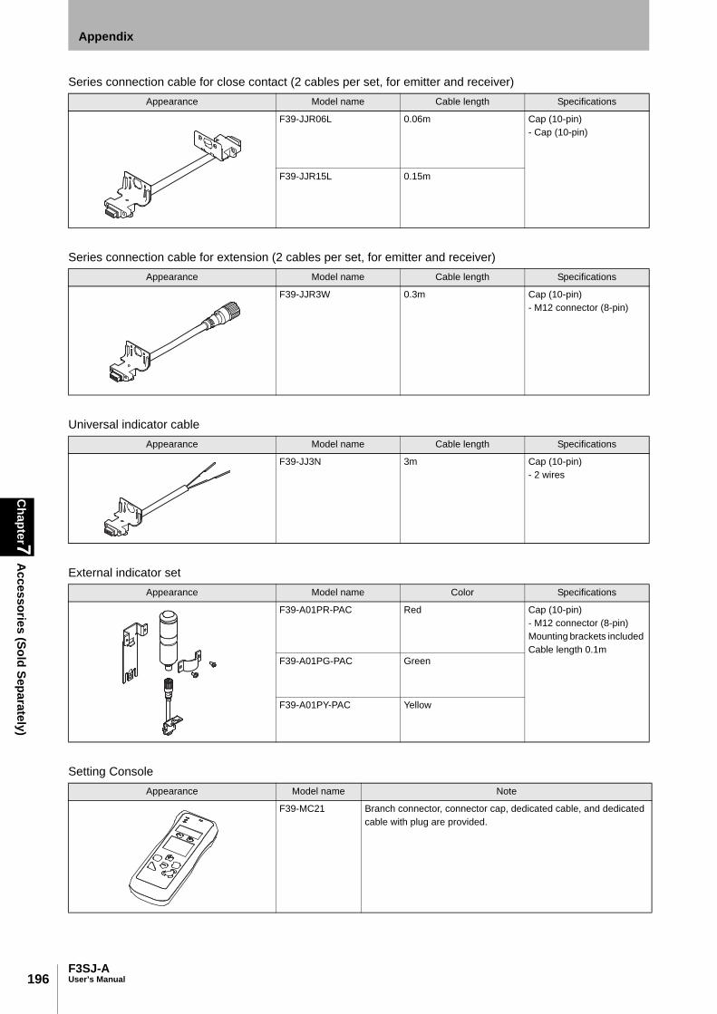
196
Chapter7
Accessories (Sold Separately)
F3SJ-AUser’s Manual
Appendix
Series connection cable for close contact (2 cables per set, for emitter and receiver)
Series connection cable for extension (2 cables per set, for emitter and receiver)
Universal indicator cable
External indicator set
Setting Console
Appearance Model name Cable length Specifications
F39-JJR06L 0.06m Cap (10-pin)- Cap (10-pin)
F39-JJR15L 0.15m
Appearance Model name Cable length Specifications
F39-JJR3W 0.3m Cap (10-pin)- M12 connector (8-pin)
Appearance Model name Cable length Specifications
F39-JJ3N 3m Cap (10-pin)- 2 wires
Appearance Model name Color Specifications
F39-A01PR-PAC Red Cap (10-pin)- M12 connector (8-pin) Mounting brackets included Cable length 0.1m
F39-A01PG-PAC Green
F39-A01PY-PAC Yellow
Appearance Model name Note
F39-MC21 Branch connector, connector cap, dedicated cable, and dedicated cable with plug are provided.
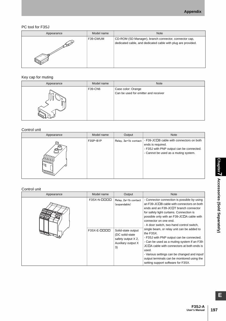
197F3SJ-A
User’s Manual
Chapter7
Accessories (Sold Separately)
Appendix
E
PC tool for F3SJ
Key cap for muting
Control unit
Control unit
Appearance Model name Note
F39-GWUM CD-ROM (SD Manager), branch connector, connector cap, dedicated cable, and dedicated cable with plug are provided.
Appearance Model name Note
F39-CN6 Case color: Orange Can be used for emitter and receiver
Appearance Model name Output Note
F3SP-B1P Relay, 3a+1b contact - F39-JCB cable with connectors on both ends is required. - F3SJ with PNP output can be connected. - Cannot be used as a muting system.
Appearance Model name Output Note
F3SX-N- Relay, 2a+1b contact
(expandable)
- Connector connection is possible by using an F39-JCB cable with connectors on both ends and an F39-JCT branch connector for safety light curtains. Connection is possible only with an F39-JCA cable with connector on one end. - A door switch, two-hand control switch, single beam, or relay unit can be added to the F3SX. - F3SJ with PNP output can be connected. - Can be used as a muting system if an F39-JCA cable with connectors at both ends is used. - Various settings can be changed and input/output terminals can be monitored using the setting support software for F3SX.
F3SX-E- Solid-state output (DC solid-state safety output X 2, Auxiliary output X 3)
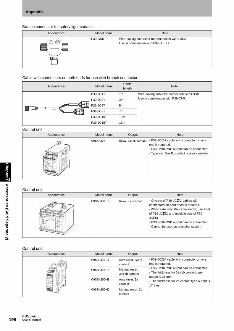
198
Chapter7
Accessories (Sold Separately)
F3SJ-AUser’s Manual
Appendix
Branch connector for safety light curtains
Cable with connectors on both ends for use with branch connector
Control unit
Control unit
Control unit
Appearance Model name Note
F39-CN5 Wire-saving connector for connection with F3SX Use in combination with F39-JCT.
Appearance Model nameCable length
Note
F39-JC1T 1m Wire-saving cable for connection with F3SX Use in combination with F39-CN5. F39-JC3T 3m
F39-JC5T 5m
F39-JC7T 7m
F39-JC10T 10m
F39-JC15T 15m
Appearance Model name Output Note
G9SA-301 Relay, 3a+1b contact - F39-JCA cable with connector on one end is required. - F3SJ with PNP output can be connected. - Type with 5a+1b contact is also available.
Appearance Model name Output Note
G9SA-300-SC Relay, 3a contact - One set of F39-JCC cables with connectors on both ends is required. - When extending the cable length, use 1 set of F39-JCC and multiple sets of F39-JCB. - F3SJ with PNP output can be connected. - Cannot be used as a muting system.
Appearance Model name Output Note
G9SB-301-B Auto reset, 3a+1b
contact
- F39-JCA cable with connector on one end is required. - F3SJ with PNP output can be connected. - The thickness for 3a+1b contact type output is 25 mm. - The thickness for 2a contact type output is 17.5 mm.
G9SB-301-D Manual reset, 3a+1b contact
G9SB-200-B Auto reset, 2a
contact
G9SB-200-D Manual reset, 2a contact

199F3SJ-A
User’s Manual
Chapter7
Accessories (Sold Separately)
Appendix
E
Control unit
Spatter protection cover (2 cables per set, common for emitter/receiver)
Protect bar (1 set, common for emitter/receiver)
Protection bracket for protect bar (4)
Appearance Model name Output Note
G9SX-AD322-T15 Solid-state output
(Instantaneous
output X 3, OFF-
delay output X 2)
- F39-JCA cable with connector on one end is required. - F3SJ with PNP output can be connected. - OFF-delay within 15 seconds can be set to 16 levels. - Use as instantaneous output is possible by setting OFF-delay output to 0 seconds. - Can be configured for partial control and total control. - Relay unit can also be connected.
Appearance Model name Note
F39-HJ In this table, the in the model indicates the same 4-digit number as the protective height ( in the model) of the F3SJ.When a spatter-proof cover is attached, operating range of F3SJ is reduced by about 10%.Spatter-proof cover with 1970 or higher of in the model is divided into 2 in combination to use.
Appearance Model name Note
F39-PJ-S One protect bar is provided in a set (common for emitter/receiver). If both of an emitter and a receiver need a protect bar respectively, you must purchase 2 sets. For side mounting of F3SJ with a width of 1001mm or wider, you must purchase protection bracket (4) for protect bar (F39-PJ-MS).
Appearance Model name Note
F39-PJ-MS Intermediate mounting bracket for side mounting using a protect bar. You must purchase 1 set for F3SJ with protective height from 1001 to 2000mm, or 2 sets for F3SJ with protective height of 2009 to 2495mm.

200
Chapter7
Accessories (Sold Separately)
F3SJ-AUser’s Manual
Appendix
Environment-resistant case
Back-mounting bracket for environment-resistant case
Side-mounting bracket for environment-resistant case
Series connection cable for environment-resistant case
Appearance Model name Note
For emitter F39-EJ-L One environment-resistant case is provided in a set.Mounting bracket is not included.You must purchase optional back-mounting bracket (F39-EJ-R) or side-mounting bracket (F39-EJ-S).When environment-resistant case is used, operating range is from 0.2 to 7m (protective height of 1649mm or less) and from 0.2 to 5m (protective height of 1655mm or more).If protective height of F3SJ is 605mm or more, only vertical mounting as shown left is available.A protective structure complies to IP67(IEC60529).
For receiver F39-EJ-D
Appearance Model name Note
F39-EJ-R 2 brackets per set
Appearance Model name Note
F39-EJ-S 2 brackets per set
Appearance Model name Note
For emitter F39-JJR3WE-L Required for series connection with an environment-resistant case. Series-connection cable for 1 set of sensors.
For receiver F39-JJR3WE-D

201F3SJ-A
User’s Manual
Chapter7
Accessories (Sold Separately)
Appendix
E
Top/bottom mounting bracket (for top/bottom mounting)
Side flat mounting bracket (4 brackets per set)
Free-location mounting bracket (also used as standard mounting bracket)
Top/bottom mounting bracket B
Mounting bracket for F3SN replacement
Appearance Model name Application Note
F39-LJ1 (Standard brackets included with the F3SJ) Purchase replacements when damaged or lost.
2 brackets for emitter, 2 brackets for receiver (4 brackets per set)
Appearance Model name Application Note
F39-LJ2 Use these small-sized brackets when performing side mounting with top/bottom mounting brackets, so that they do not protrude from the detection surface.
2 brackets for emitter, 2 brackets for receiver (4 brackets per set) (Use in combination with top/bottom mounting brackets)
Appearance Model name Application Note
F39-LJ3 Brackets for mounting in any location without using top/bottom mounting brackets. Side mounting and backside mounting are possible.
2 brackets per set Same as the intermediate mounting brackets included for F3SJ with protective height larger than 595mm.
Appearance Model name Application Note
F39-LJ4 Mounting bracket used when replacing existing zone sensors with the F3SJ. Suitable for mounting hole pitch of 18 to 20mm.
2 brackets for emitter, 2 brackets for receiver (4 brackets per set) (Use in combination with top/bottom mounting brackets)
Appearance Model name Application Note
F39-LJ5 Mounting bracket used when an F3SN with protective height of 300mm or less is replaced by an F3SJ.
2 brackets for emitter, 2 brackets for receiver (4 brackets per set) (Use in combination with top/bottom mounting brackets)

202
Chapter7
Accessories (Sold Separately)
F3SJ-AUser’s Manual
Appendix
Space-saving mounting bracket
Mounting bracket for F3W-C replacement
Top/bottom mounting bracket C
Appearance Model name Application Note
F39-LJ8 Brackets that can save mounting space for top and bottom
2 brackets for an emitter, 2 for a receiver (4 brackets per set)
Appearance Model name Application Note
F39-LJ9 Mounting bracket used when replacing existing zone sensors F3W-C series with the F3SJ.
2 brackets for an emitter, 2 for a receiver (4 brackets per set)
Appearance Model name Application Note
F39-LJ11 Mounting bracket used when replacing existing area sensors with the F3SJ. Suitable for mounting hole pitch of 12 to 14mm.
2 brackets for emitter, 2 brackets for receiver (4 brackets per set)

203F3SJ-A
User’s Manual
Chapter7
Glossary
Appendix
E
Glossary
Term Definition
A Access qualification Function that requires a password to change setting to prevent careless change of F3SJ’s functional setting.
Accumulated load switching frequency
This value indicates the cumulative value for load switching frequency, from when power was first supplied to the F3SJ until the present.
Administrator level Mode for F3SJ’s functional setting change. Password input is required to log in to this mode because of access qualification.
Allowable delay time The allowable amount of time from when the safety output changes until the external device monitoring input changes. The F3SJ enters lockout if this time is exceeded.
Auto reset Setting status by which the safety output automatically turns ON when the F3SJ receives light after the power is turned ON and after the F3SJ is blocked.
Auxiliary output 1 Allows output appropriate for the setting. This CANNOT be used for safety applications.
Auxiliary output 2 Allows output appropriate for the setting. This CANNOT be used for safety applications. When a muting enabling key cap (F39-CN6) is attached, this output is used as a muting input.
Auxiliary output diagnosis function
Detects breakage and short-circuits for the muting lamp or external indicator connected to auxiliary output 1.
B Basic system This refers to the F3SJ in the state it is in when purchased. The basic system provides basic safety light curtain functions. Most functions can be used without performing additional configuration.
Blanking zone A range of consecutive beams for which fixed or floating blanking is configured.
Breakage detection This function puts the F3SJ in lockout when there is broken connection between the output terminals for the external indicator.
D Designated beam interruption information
ON is output when any of the designated beams are interrupted. Beams must be designated if this output operation is selected.
Designated beam output Provides output based on incidence/interruption status of a designated beam. Destination can be assigned to auxiliary output or external indicator output.
Detection capability Minimum size of an object that can be detected in the protective height of the F3SJ.
Disturbance light level display
This display can read out the disturbance light level of the F3SJ. For the PC tool for F3SJ, the level can be checked using a graph.
E Effective aperture angle (EAA)
Range of angles for which the F3SJ can operate.
End beam disable mode If either end beam of the F3SJ is set as a floating beam, its status as a floating beam target is cancelled.
Error/lockout information This information is output from the auxiliary output or external indicator when an error or lockout occurs. Note that the error/lockout information must be assigned to an output destination.
Exit only muting delay time
The OFF delay time from when the signal of muting input 1 or 2 turns OFF until the muting state is cancelled.
Exit only muting mode Used when there is only enough space to install a muting sensor on one end of the F3SJ.
External device monitoring function(EDM)
Function that detects malfunctions, such as welding, in external relays (or contactors) that control the hazardous zone of a machine, by monitoring the operation of N.C. contact.
External indicator diagnosis function
Detects breakage and short-circuits for the muting lamp or external indicator connected to the external indicator output.
External Indicator Output 1
Allows configuration of receiver's output based on settings. This CANNOT be used for safety applications.
External Indicator Output 2
Allows configuration of emitter's output based on settings. This CANNOT be used for safety applications.
External test Function that stops emission at any time to check that the safety output is being properly turned OFF.
F Fixed blanking Disables part of F3SJ's operation range. Safety output will not change even if an object enters the disabled zone.
Fixed blanking monitoring function
This function puts the F3SJ in lockout state when part of the fixed blanking zone is interrupted.
Fixed blanking zone This refers to the zone set in the fixed blanking function. One zone can be set by the setting console, and 5 zones can be set by the PC tool for F3SJ.
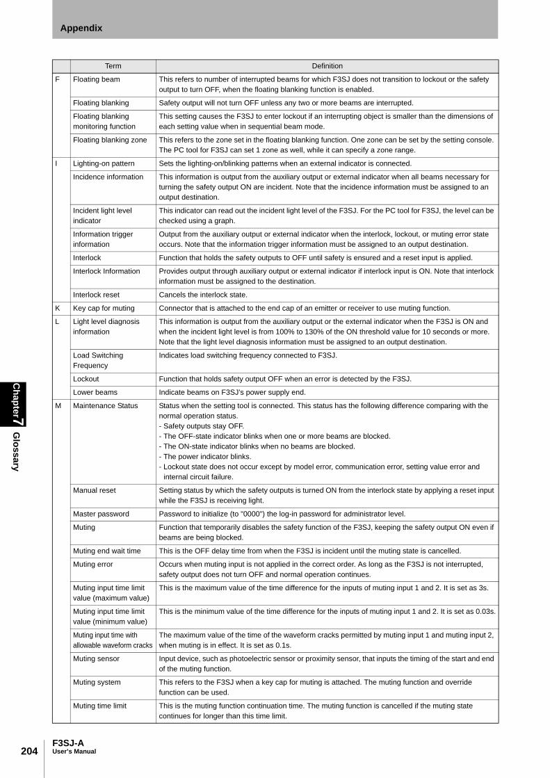
204
Chapter7
Glossary
F3SJ-AUser’s Manual
Appendix
F Floating beam This refers to number of interrupted beams for which F3SJ does not transition to lockout or the safety output to turn OFF, when the floating blanking function is enabled.
Floating blanking Safety output will not turn OFF unless any two or more beams are interrupted.
Floating blanking monitoring function
This setting causes the F3SJ to enter lockout if an interrupting object is smaller than the dimensions of each setting value when in sequential beam mode.
Floating blanking zone This refers to the zone set in the floating blanking function. One zone can be set by the setting console. The PC tool for F3SJ can set 1 zone as well, while it can specify a zone range.
I Lighting-on pattern Sets the lighting-on/blinking patterns when an external indicator is connected.
Incidence information This information is output from the auxiliary output or external indicator when all beams necessary for turning the safety output ON are incident. Note that the incidence information must be assigned to an output destination.
Incident light level indicator
This indicator can read out the incident light level of the F3SJ. For the PC tool for F3SJ, the level can be checked using a graph.
Information trigger information
Output from the auxiliary output or external indicator when the interlock, lockout, or muting error state occurs. Note that the information trigger information must be assigned to an output destination.
Interlock Function that holds the safety outputs to OFF until safety is ensured and a reset input is applied.
Interlock Information Provides output through auxiliary output or external indicator if interlock input is ON. Note that interlock information must be assigned to the destination.
Interlock reset Cancels the interlock state.
K Key cap for muting Connector that is attached to the end cap of an emitter or receiver to use muting function.
L Light level diagnosis information
This information is output from the auxiliary output or the external indicator when the F3SJ is ON and when the incident light level is from 100% to 130% of the ON threshold value for 10 seconds or more. Note that the light level diagnosis information must be assigned to an output destination.
Load Switching Frequency
Indicates load switching frequency connected to F3SJ.
Lockout Function that holds safety output OFF when an error is detected by the F3SJ.
Lower beams Indicate beams on F3SJ’s power supply end.
M Maintenance Status Status when the setting tool is connected. This status has the following difference comparing with the normal operation status.- Safety outputs stay OFF.- The OFF-state indicator blinks when one or more beams are blocked.- The ON-state indicator blinks when no beams are blocked. - The power indicator blinks.- Lockout state does not occur except by model error, communication error, setting value error and
internal circuit failure.
Manual reset Setting status by which the safety outputs is turned ON from the interlock state by applying a reset input while the F3SJ is receiving light.
Master password Password to initialize (to "0000") the log-in password for administrator level.
Muting Function that temporarily disables the safety function of the F3SJ, keeping the safety output ON even if beams are being blocked.
Muting end wait time This is the OFF delay time from when the F3SJ is incident until the muting state is cancelled.
Muting error Occurs when muting input is not applied in the correct order. As long as the F3SJ is not interrupted, safety output does not turn OFF and normal operation continues.
Muting input time limit value (maximum value)
This is the maximum value of the time difference for the inputs of muting input 1 and 2. It is set as 3s.
Muting input time limit value (minimum value)
This is the minimum value of the time difference for the inputs of muting input 1 and 2. It is set as 0.03s.
Muting input time with allowable waveform cracks
The maximum value of the time of the waveform cracks permitted by muting input 1 and muting input 2, when muting is in effect. It is set as 0.1s.
Muting sensor Input device, such as photoelectric sensor or proximity sensor, that inputs the timing of the start and end of the muting function.
Muting system This refers to the F3SJ when a key cap for muting is attached. The muting function and override function can be used.
Muting time limit This is the muting function continuation time. The muting function is cancelled if the muting state continues for longer than this time limit.
Term Definition

205F3SJ-A
User’s Manual
Chapter7
Glossary
Appendix
E
N Non-sequential beam mode
In this mode, interruption is determined to have occurred when the total number of interrupted beams is equal to or greater than the number of beams specified in the setting.
Number of Allowable Beams
Allowable fixed blanking beams.It represents a beam out of the target of fixed blanking monitoring although it is a fixed blanking zone.
Allowable floating blanking beams.F3SJ enters lockout if a size gets under setting value for contiguous floating mode with monitoring function enabled.
Number of floating beams
This setting causes the F3SJ output to turn OFF if an interrupting object is larger than each setting value, when the floating blanking function is enabled.
O Operating range change function
This function changes the operating range according to the F3SJ installation distance.
Output operation mode Details that are output from the auxiliary output or external indicator output.
Override Function that forcibly turns the safety output ON when the muting function is not working.
Override time limit The continuation time of the override function. The override state is cancelled if it continues for longer than this time limit.
P PC tool for F3SJ Setting tool that connects to a PC and makes settings with setting software (SD Manager). Setting and monitoring of all functions is possible.
Position detection muting mode
Mode that enables the muting function with heterogeneous redundant input.
Power-on time This is the current power-on time since the power-on time was last reset.
Power-on time information
This information is output from the auxiliary output or external indicator when the power-on time exceeds the power-on time threshold value. Note that the power-on time information must be assigned to an output destination.
Power-on time reset This function can reset the power-on time of the F3SJ to 0. In the case of series connection, the power-on time can be reset for each F3SJ CH.
Power-on time threshold value
This can be output from the auxiliary output or the external indicator output when the power-on time exceeds this value.Note that the power-on time information must be assigned to an output mode.
Primary sensor Name of the F3SJ connected nearest the power supply when series-connected.
R Reset Releases the interlock state/lockout state.
Response time from ON to OFF
Time period from when the F3SJ is blocked until the safety output turns from ON to OFF.
Restart interlock Enters interlock state when the F3SJ is blocked.
Reverse output mode In this mode, the logic of the auxiliary output and external indicator output is reversed.
S Safety output (OSSD) Outputs +24V when receiving light. Can be used for safety applications.
Safety output information
This information is output from the auxiliary output or external indicator when the auxiliary output turns ON. Note that safety output information must be assigned to an output destination.
SD Manager Setting software that is used for the PC tool for F3SJ. Setting and monitoring of all functions is possible.
Secondary sensor Name used for F3SJ other than the primary sensor, when series-connected.
Sequential beam mode In this mode, output ON continues even when interrupted, if an interrupting object is within the range of the specified size in one contiguous zone.
Setting console Convenient tool for changing and monitoring settings. The setting console can be carried to the site. There are some functions that cannot be used.
Setting recovery Function to restore the F3SJ's factory settings or the settings made before the most recent change.
Setting tool This refers to the F39-MC21 setting console and the F39-GWUM PC tool for F3SJ.
Short-circuit detection This function puts the F3SJ in lockout when there is short-circuit between the output terminals for the external indicator.
Standard muting mode This mode is set as the default factory setting and is used when there is enough space to install muting sensors at both ends of the F3SJ.
Start interlock Enters interlock after power is turned ON.
Status information display
This display can read out the I/O data and status of the F3SJ. This function is available only for the PC tool for F3SJ.
Term Definition

206
Chapter7
Glossary
F3SJ-AUser’s Manual
Appendix
T Teaching Function that configures a target beam as interrupted for following functional settings.- Muting function- Fixed blanking function- Floating blanking function- Warning Zone function- Designated beam output function
Test input ON information
The external indicator turns ON when the test input is ON. When the test input is ON, the F3SJ activates the external diagnosis function.
U Upper beams Indicate beams on F3SJ’s terminal.
User level Mode that reads receiving light intensity and monitors F3SJ’s operating status such as disturbance light measurement by the setting tool. Password is not required to transition to this mode.
W Warning zone information
This information is output from the auxiliary output or the external indicator when the warning zone is blocked. Note that the warning zone information must be assigned to an output destination.
Warning zone function When part of the detection zone is configured as a warning zone, the unblocked/blocked status of the zone does not affect the safety output. Instead, the unblocked/blocked status can be output from the auxiliary output, etc.
Term Definition

207F3SJ-A
User’s Manual
Chapter7
Related Standards
Appendix
E
Related Standards
International Standards• IEC61496-1:2004 Safety of machinery - Electro-sensitive protective equipment - Part 1: General
requirements and tests• IEC61496-2:2004 CDV Safety of machinery - Electro-sensitive protective equipment - Part 2: Particular
requirements for equipment using active opto-electronic protective devices• IEC61508-1 to 3:2001 Functional safety of electrical/electronic/programmable electronic safety-related systems• ISO13855:2002 Safety of machinery - Positioning of protective equipment with respect to the approach
speeds of parts of the human body• ISO 13849-1: 2006 Safety of machinery - Safety-related parts of control systems - Part 1: General
principles for design
European Standards• EN ISO 13849-1:2008 Safety of machinery - Safety-related parts of control systems - Part 1: General
principles for design• EN61496-1:2004 Safety of machinery - Electro-sensitive protective equipment - Part 1: General
requirements and tests• CLC/TS 61496-2:2006 Safety of machinery - Electro-sensitive protective equipment - Part 2: Particular
requirements for equipment using active opto-electronic protective devices• EN61508-1 through -3:2001 Functional safety of electrical/electronic/programmable electronic safety-
related systems • EN954-1:1996 Safety of Machinery - Safety-related parts of control systems - Part 1: General principles
for design• EN415-4:1997 Palletisers and depalletisers• EN692:1996 Mechanical presses• EN693:2001 Hydraulic presses•EN999:1999 Safety of machinery - Positioning of protective equipment with respect to the approach
speeds of parts of the human body• EN1037:1995 Safety of machinery : Preventation of unexpected start-up
U.S. Federal Regurations•OSHA 29 CFR 1910.212 General requirements for all machines•OSHA 29 CFR 1910.217 Mechanical power presses
U.S. Standards• ANSI B11.1:2001 Mechanical power presses• ANSI B11.2:1995(R2005) Hydraulic power presses• ANSI B11.3:2002 Power press brakes• ANSI B11.4:2003 Metal shears• ANSI B11.5:1988(R2002) Iron workers• ANSI B11.6:2001 Lathes• ANSI B11.7:1995(R2005) Cold headers and cold formers• ANSI B11.8:2001 Drilling, milling, and boring machines• ANSI B11.9:1975(R2005) Grinding machines• ANSI B11.10:2003 Metal sawing machines

208
Chapter7
Related Standards
F3SJ-AUser’s Manual
Appendix
• ANSI B11.11:2001 Gear cutting machines• ANSI B11.12:2005 Roll forming and roll bending machines• ANSI B11.13:1992(R1998) Single- and multiple-spindle automatic bar and chucking machines• ANSI B11.14:1996 Coil slitting machines/systems• ANSI B11.15:2001 Pipe, tube, and shape bending machines• ANSI B11.16:2003 Metal powder compacting presses• ANSI B11.17:2004 Horizontal hydraulic extrusion presses• ANSI B11.18:1997 Machines and machinery systems for processing strip, sheet or plate from coiled
configuration• ANSI B11.19:2003 Performance criteria for the design, construction, care, and operation of safeguarding
when referenced by the other B11 machine tool safety standards• ANSI/RIA 15.06:1999 Industrial robots & robot systems safety requirements• UL1998:1998 Safety-related software• UL508:1999 Industrial control equipment• UL61496-1:2002 Electro-sensitive protective equipment - Part 1: General requirements and tests• UL61496-2:2002 Electro-sensitive protective equipment - Part 2: Particular requirements for active opto-
electronic protective devices
Canadian Standards• CAN/CSA 22.2 No.14-05 Industrial control equipment• CAN/CSA 22.2 No.08-M1986(R2003) Electronics integrated safety functions• CSA Z142-02 Code for power press operation: Health, safety, and guarding requirements• CSA Z432-04 Safeguarding of machinery• CCSA Z434-03 Industrial robots and robot systems : General safety requirements
SEMI Standards• SEMI S2-0703 Environmental, health, and safety guideline for semiconductor manufacturing equipment
JIS Standards• JIS B 9704-1:2000 Safety of machinery - Electro-sensitive protective equipment - Part 1 : General
requirements and tests• JIS B 9704-2:2000 Safety of machinery - Electro-sensitive protective equipment - Part 2 : Particular
requirements for equipment using active opto-electronic protective devices

209F3SJ-A
User’s Manual
Chapter7
Revision H
istoryAppendix
E
Revision HistoryA manual revision code appears as a suffix to the manual number at the bottom of the front and back coversof this manual.
Revisionsymbol
Revision date Revisions
B November, 2005 First edition
C February, 2006 Minor correction
D May, 2006 Minor correction
E December, 2006 Added F3SJ-AP55
F July, 2007 Added F3SJ-AP25 Troubleshooting revised
G August, 2008 Changed mounting screw. Added information to "Precautions for Correct Use".
H January, 2010 Added the contents about new Machinery Directives Minor correction
I November, 2011 Added the contents about EN ISO13849-1:2008 Change the contents about EN 61496-2
J November, 2012 Added and corrected dimensions and notes.Corrected the contents about EN 61508.Correction of errors.
Revision No.
SCHG-718 J

Authorized Distributor:
In the interest of product improvement, specifications are subject to change without notice.
Cat No. SCHG-718J
© OMRON Corporation 2005-2012 All Rights Reserved.
OMRON Corporation Industrial Automation Company
Regional HeadquartersOMRON EUROPE B.V.Wegalaan 67-69-2132 JD HoofddorpThe NetherlandsTel: (31)2356-81-300/Fax: (31)2356-81-388
Contact: www.ia.omron.comTokyo, JAPAN
OMRON ASIA PACIFIC PTE. LTD.No. 438A Alexandra Road # 05-05/08 (Lobby 2), Alexandra Technopark, Singapore 119967Tel: (65) 6835-3011/Fax: (65) 6835-2711
OMRON (CHINA) CO., LTD.Room 2211, Bank of China Tower, 200 Yin Cheng Zhong Road, PuDong New Area, Shanghai, 200120, ChinaTel: (86) 21-5037-2222/Fax: (86) 21-5037-2200
OMRON SCIENTIFIC TECHNOLOGIES INC.6550 Dumbarton Circle Fremont, CA 94555-3605 U.S.A.Tel: (1) 510-608-3400/Fax: (1) 510-744-1442
0997622-6J