model f3sj-e p25 f3sj-b p25
TRANSCRIPT
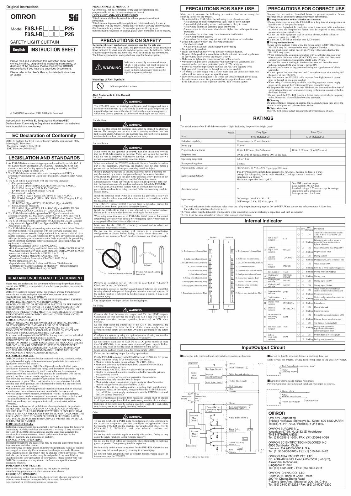
Model F3SJ-E □□□□P25 F3SJ-B □□□□P25
1. An F3SJ-E/B does not receive type approval provided by Article 44-2 of the Labour Safety and Health Law of Japan. Therefore, the F3SJ-E/B cannot be used as a "safety system for pressing or shearing machines" prescribed in Article 42 of that law.
2. The F3SJ-E/B is electro-sensitive protective equipment (ESPE) in accordance with European Union (EU) Machinery Directive Index Annex V, Item 2.
3. The F3SJ-E/B is in conformity with the following standards:(1) European standards
EN 61496-1 (Type 4 ESPE), CLC/TS 61496-2 (Type 4 AOPD), EN 61508-1 through -3 (SIL3), EN 61000-6-4, EN ISO 13849-1:2008 (Category 4, PL e)
(2) International standardsIEC 61496-1 (Type 4 ESPE), IEC 61496-2 (Type 4 AOPD), IEC 61508-1 through -3 (SIL3), ISO 13849-1:2006 (Category 4, PLe)
(3) JIS standardsJIS B 9704-1 (Type 4 ESPE), JIS B 9704-2 (Type 4 AOPD)
(4) North American Standards:UL 61496-1 (Type 4 ESPE), UL 61496-2 (Type 4 AOPD), UL 508, UL 1998, CAN/CSA C22.2 No.14, CAN/CSA C22.2 No.08
4. The F3SJ-E/B received the approvals of EC Type-Examination in accordance with the EU Machinery Directive, Type 4 ESPE and Type 4 AOPD from the EU accredited body, TÜV SÜD Product Service GmbH.
5. The F3SJ-E/B received the certificates of UL listing for US and Canadian safety standards, Type 4 ESPE and Type 4 AOPD from the Third Party Assessment Body UL.
6. The F3SJ-E/B is designed according to the standards listed below. To make sure that the final system complies with the following standards and regulations, you are asked to design and use it in accordance with all other related standards, laws, and regulations. If you have any questions, consult with specialized organizations such as the body responsible for prescribing and/or enforcing machinery safety regulations in the location where the equipment is to be used.•European Standards: EN415-4, EN692, EN693•U.S. Occupational Safety and Health Standards: OSHA 29 CFR 1910.212•U.S. Occupational Safety and Health Standards: OSHA 29 CFR 1910.217•American National Standards: ANSI B11.1 to B11.19•American National Standards: ANSI/RIA 15.06•Canadian Standards Association CSA Z142, Z432, Z434•SEMI Standards SEMI S2•Japan Ministry of Health, Labour and Welfare "Guidelines for Comprehensive Safety Standards of Machinery", Standard Bureau's Notification No. 0731001 dated July 31, 2007.
© OMRON Corporation 2011 All Rights Reserved.
LEGISLATION AND STANDARDS
OMRON declares that F3SJ is in conformity with the requirements of the following EC Directives: Machinery Directive 2006/42/EC EMC Directive 2004/108/EC
EC Declaration of Conformity
Please read and understand this document before using the products. Please consult your OMRON representative if you have any questions or comments.WARRANTYOMRON’s exclusive warranty is that the products are free from defects in materials and workmanship for a period of one year (or other period if specified) from date of sale by OMRON.OMRON MAKES NO WARRANTY OR REPRESENTATION, EXPRESS OR IMPLIED, REGARDING NONINFRINGEMENT, MERCHANTABILITY, OR FITNESS FOR PARTICULAR PURPOSE OF THE PRODUCTS. ANY BUYER OR USER ACKNOWLEDGES THAT THE BUYER OR USER ALONE HAS DETERMINED THAT THE PRODUCTS WILL SUITABLY MEET THE REQUIREMENTS OF THEIR INTENDED USE. OMRON DISCLAIMS ALL OTHER WARRANTIES, EXPRESS OR IMPLIED.LIMITATIONS OF LIABILITYOMRON SHALL NOT BE RESPONSIBLE FOR SPECIAL, INDIRECT, OR CONSEQUENTIAL DAMAGES, LOSS OF PROFITS OR COMMERCIAL LOSS IN ANY WAY CONNECTED WITH THE PRODUCTS, WHETHER SUCH CLAIM IS BASED ON CONTRACT, WARRANTY, NEGLIGENCE, OR STRICT LIABILITY.In no event shall responsibility of OMRON for any act exceed the individual price of the product on which liability is asserted.IN NO EVENT SHALL OMRON BE RESPONSIBLE FOR WARRANTY, REPAIR, OR OTHER CLAIMS REGARDING THE PRODUCTS UNLESS OMRON’S ANALYSIS CONFIRMS THAT THE PRODUCTS WERE PROPERLY HANDLED, STORED, INSTALLED, AND MAINTAINED AND NOT SUBJECT TO CONTAMINATION, ABUSE, MISUSE, OR INAPPROPRIATE MODIFICATION OR REPAIR.SUITABILITY FOR USEOMRON shall not be responsible for conformity with any standards, codes, or regulations that apply to the combination of products in the customer’s application or use of the product.At the customer’s request, OMRON will provide applicable third party certification documents identifying ratings and limitations of use that apply to the products. This information by itself is not sufficient for a complete determination of the suitability of the products in combination with the end product, machine, system, or other application or use.The following are some examples of applications for which particular attention must be given. This is not intended to be an exhaustive list of all possible uses of the products, nor is it intended to imply that the uses listed may be suitable for the products:• Outdoor use, uses involving potential chemical contamination or electrical
interference, or conditions or uses not described in this document.• Nuclear energy control systems, combustion systems, railroad systems,
aviation systems, medical equipment, amusement machines, vehicles, and installations subject to separate industry or government regulations.
• Systems, machines, and equipment that could present a risk to life or property.
Please know and observe all prohibitions of use applicable to the products.NEVER USE THE PRODUCTS FOR AN APPLICATION INVOLVING SERIOUS RISK TO LIFE OR PROPERTY WITHOUT ENSURING THAT THE SYSTEM AS A WHOLE HAS BEEN DESIGNED TO ADDRESS THE RISKS, AND THAT THE OMRON PRODUCT IS PROPERLY RATED AND INSTALLED FOR THE INTENDED USE WITHIN THE OVERALL EQUIPMENT OR SYSTEM.PERFORMANCE DATAPerformance data given in this document is provided as a guide for the user in determining suitability and does not constitute a warranty. It may represent the result of OMRON’s test conditions, and the users must correlate it to actual application requirements. Actual performance is subject to the OMRON Warranty and Limitations of Liability.CHANGE IN SPECIFICATIONSProduct specifications and accessories may be changed at any time based on improvements and other reasons.It is our practice to change model numbers when published ratings or features are changed, or when significant construction changes are made. However, some specifications of the product may be changed without any notice. Whenin doubt, special model numbers may be assigned to fix or establish key specifications for your application on your request. Please consult with your OMRON representative at any time to confirm actual specifications of purchased products.DIMENSIONS AND WEIGHTSDimensions and weights are nominal and are not to be used for manufacturing purposes, even when tolerances are shown.ERRORS AND OMISSIONSThe information in this document has been carefully checked and is believed to be accurate; however, no responsibility is assumed for clerical, typographical, or proofreading errors, or omissions.
READ AND UNDERSTAND THIS DOCUMENT
Alert Statements in this Manual
Meanings of Alert Symbols
Please read and understand this instruction sheet before storing, installing, programming, operating, maintaining, or disposing of the products. Please consult your OMRON representative if you have any questions or comments.
Please refer to the User’s Manual for detailed instructions on usage.
Regarding the alert symbols and meanings used for the safe usesIn order to use the F3SJ-E/B safely, the precautions listed in this Instruction Sheet indicated by alert symbols and descriptions must be followed. Failure to follow all precautions and alerts may result in an unsafe use or operation.The following indications and symbols are used for the descriptions.
The F3SJ-E/B must be installed, configured, and incorporated into a machine control system by a sufficiently trained and qualified person. An unqualified person may not be able to perform these operations properly,which may cause a person to go undetected, resulting in serious injury.
Do not use this sensor for machines that cannot be stopped by electrical control. For example, do not use it for a pressing machine that uses full-rotation clutch. Otherwise, the machine may not stop before a personreaches the hazardous part, resulting in serious injury.
Make sure to test the operation of the F3SJ-E/B after installation to verify that the F3SJ-E/B operates as intended. Make sure to stop the machine until the test is complete. Unintended function settings may cause a person to go undetected, resulting in serious injury.
Install a protective structure so that the hazardous part of a machine can only be reached by a person that passes through the sensor's detection zone. Install the sensors so that part of the person is always present in the detection zone when working in a machine's hazardous zones, eliminating areas where the sensors do not reach. If a person is able step into the hazardous zone of a machine and remain behind the F3SJ-E/B's detection zone, configure the system with an interlock function that prevents the machine from being restarted. Failure to do so may result in serious injury.
Make sure to install the F3SJ-E/B at the safe distance from the hazardous part of the equipment. Otherwise, the machine may not stop before a person reaches the hazardous part, resulting in serious injury.
Install the interlock reset switch in a location that provides a clear view of the entire hazardous zone and where it cannot be activated from within the hazardous zone.The F3SJ-E/B cannot protect a person from a projectile exiting the hazardous zone. Install protective cover(s) or fence(s).Install the F3SJ-E/B so that it is not affected by a reflective surface. Failure to do so may hinder detection, resulting in serious injury. When using more than one set of F3SJ-E/Bs, install them so that mutual interference does not occur, such as by configuring series connections or using physical barriers between adjacent sets.Make sure that the F3SJ-E/B is securely mounted and its cables and connectors are properly secured.Do not use the sensor system with mirrors in a retro-reflective configuration as shown below. Doing so may hinder detection. It is possible to use mirrors to "bend" the detection zone to a 90-degree angle.
Install muting sensors so that they can distinguish between the object that is being allowed to be passed through the detection zone and a person. If the muting function is activated by the detection of a person, it may result in serious injury.
Use independent two input devices for muting inputs.
Connect the load between the output and 0V line (PNP output). Connecting the load between the output and +24 V line will result in a dangerous condition because operation is reversed to "ON when blocked".Do not short-circuit the output line to the +24 V line. Otherwise, the output is always ON. Also, the 0 V of the power supply must be grounded so that output does not turn ON due to grounding of the output line.Configure the system by using the optimal number of safety outputs that satisfy the requirements of the necessary safety category.
Make sure to perform wiring while the power supply is OFF.
Do not connect each line of F3SJ-E/B to a DC power supply of more than 24 VDC+20%. Also, do not connect to an AC power supply. Failure to do so may result in electric shock or breakdown of the device.
Do not use the auxiliary output for safety applications.
Double or reinforced insulation from hazardous voltage must be applied to all input and output lines. Failure to do so may result in electric shock.
Do not try to disassemble, repair, or modify this product. Doing so may cause the safety functions to stop working properly.Do not use the F3SJ-E/B in environments where flammable or explosive gases are present. Doing so may result in explosion.
Perform daily and 6-month inspections for the F3SJ-E/B. Otherwise, the system may fail to work properly, resulting in serious injury.Do not use radio equipment such as cellular phones, walkie-talkies, or transceivers near the F3SJ-E/B.
Extension of the cable must be within a specified length. If it isn't, safety function may not work properly, resulting in danger.
To use the F3SJ-E/B in PSDI mode (Reinitiation of cyclic operation by the protective equipment), you must configure an appropriate circuit between the F3SJ-E/B and the machine. For details about PSDI, refer to OSHA1910.217, IEC61496-1, and other relevant standards and regulations.
For the F3SJ-E/B to comply with IEC61496-1 and UL508, the DC power supply unit must satisfy all of the following conditions:• Must be within the rated power voltage (24 V DC ± 20%)• Must have tolerance against the total rated current of devices if it is
connected to multiple devices• Must comply with EMC directives (industrial environment)• Double or reinforced insulation must be applied between the primary
and secondary circuits• Automatic recovery of overcurrent protection characteristics• Output holding time must be 20ms or longer• Must satisfy output characteristic requirements for class 2 circuit or
limited voltage current circuit defined by UL508• Must comply with laws and regulations, regarding EMC and electrical
equipment safety, of the country or region where the F3SJ-E/B is used (Ex: In EU, the power supply must comply with the EMC Directive and the Low Voltage Directive.)
Perform an inspection for all F3SJ-E/B as described in "Chapter 5 Checklists" in the User's Manual.
PRECAUTIONS ON SAFETY
Make sure to observe the following precautions that are necessary for ensuring safe use of the product.• Do not install the F3SJ-E/B in the following types of environments:
-Areas exposed to intense interference light, such as direct sunlight-Areas with high humidity where condensation is likely to occur-Areas where oil mist or corrosive gases are present-Areas exposed to vibration or shock levels higher than in the specification
provisions-Areas where the product may come into contact with water-Areas with pollution degree 3-Areas where the product may get wet with oil that can solve adhesive
• Loads must satisfy both of the following conditions:-Not short-circuited-Not used with a current that is higher than the rating
• Do not drop the product.• Install the emitter and receiver to the same vertical direction.• Dispose of the product in accordance with the relevant rules and regulations
of the country or area where the product is used.• Make sure to tighten the connectors of the cables securely.• When replacing the cable connectors with other types of connectors, use
connectors that provide a protection grade of IP54 or higher.• Be sure to route the input/output lines for the F3SJ-E/B separate from
high-potential power lines or through an exclusive conduit.• To extend a cable length with a cable other than the dedicated cable, use
cable with the same or superior specifications.• The cable extension length must be within the specified length (30 m max).• In environments where foreign material such as spatter adheres to the
F3SJ-E/B, attach a cover to protect the F3SJ-E/B from the spatter.
PRECAUTIONS FOR SAFE USEObserve the precautions described below to prevent operation failure, malfunctions, or undesirable effects on product performance.■Storage conditions and installation environment• Do not install, use, or store the F3SJ-E/B for a long time at a temperature or
humidity out of the specified range.• This is a class A product. In residential areas it may cause radio interference,
in which case the Responsible Person may be required to take adequate measures to reduce interference.
• Do not use radio equipment such as cellular phones, walkie-talkies, or transceivers near the F3SJ-E/B.
• Do not use F3SJ-E/B at altitudes over 1,000 meters.■Wiring and installation• Make sure to perform wiring while the power supply is OFF. Otherwise, the
F3SJ-E/B may fail to operate due to the diagnosis function.• Do not short-circuit output lines to +24 V line. Otherwise a fault of the
F3SJ-E/B may occur.• When extending the communication line with a cable (twisted-pair wire)
other than the dedicated cable (F39-JD��), use a cable with the same or superior specifications. Connect the shield to the 0V line.
• Be sure that there is nothing in the detection zone and the stable-state indicator is turned ON after power is turned ON.
• Properly perform the wiring after confirming the signal names of all the terminals.
• Do not operate the control system until 2 seconds or more after turning ON the power of the F3SJ-E/B.
• Be sure to route the F3SJ-E/B cable separate from high-potential power lines or through an exclusive conduit.
• When using a commercially available switching regulator power supply, make sure to ground the FG terminal (frame ground terminal).
• If the protective height is more than 1105mm, use Intermediate Brackets of specified quantities and locations according to the dimensions described in the User's Manual.
• Do not install the F3SJ-E/B close to a device that generates high-frequency noise. Otherwise, take sufficient blocking measures.■CleaningDo not use thinner, benzene, or acetone for cleaning, because they affect the product's resin parts and paint on the extrusion.■Object detectionThe F3SJ-E/B cannot detect transparent and/or translucent objects.
PRECAUTIONS FOR CORRECT USE
RATINGS
Internal Indicator
Input/Output Circuit
Indicates a potentially hazardous situation which, if not avoided, will result in minor or moderate injury, or may result in serious injury or death. Additionally there may be significant property damage.
WARNING
WARNING
WARNING
WARNING
WARNING
WARNING
For Users
For Machines
For Installation
For Wiring
Other
OMRON CorporationShiokoji Horikawa, Shimogyo-ku, Kyoto, 600-8530 JAPANTel:(81)75-344-7093 / Fax:(81)75-344-8197
OMRON EUROPE B.V.Wegalaan 67-69, NL-2132 JD HoofddorpTHE NETHERLANDSTel: (31)-2356-81-300 / FAX: (31)-2356-81-388
OMRON SCIENTIFIC TECHNOLOGIES INC.6550 Dumbarton CircleFremont, CA 94555-3605 U.S.A.Tel: (1) 510-608-3400 / Fax: (1) 510-744-1442
OMRON ASIA PACIFIC PTE. LTD.No. 438A Alexandra Road # 05-05/08 (Lobby 2),Alexandra Technopark,Singapore 119967Tel: (65) 6835-3011 / Fax: (65) 6835-2711
OMRON (CHINA) CO., LTD.Room 2211, Bank of China Tower,200 Yin Cheng Zhong Road,PuDong New Area, Shanghai, 200120, ChinaTel: (86) 21-5037-2222 / Fax: (86) 21-5037-2200
Original instructions
Instructions in the official EU languages and a signed EC Declaration of Conformity in English are available on our website at www.industrial.omron.eu/safety.
Indicates prohibited actions.
Reflector
Position with retro-reflectionPosition with detection zone bent at 90°
Reflector
The model names of the F3SJ-E/B contain the 4 digits indicating the protective height (mm).
ItemModel
Detection capability
Beam gap
Protective height (mm)
Response time
Operating range (m)
Startup waiting time
Power supply voltage (Vs)
Safety output (OSSD)
Auxiliary output
Input voltage
Easy Type Basic Type
F3SJ-E����P25 F3SJ-B����P25
Opaque objects, 25 mm diameter
20 mm
185 to 1,105 mm (8 to 54 beams)
ON to OFF: 15 ms max, OFF to ON: 70 ms max.
2 s max.
SELV/PELV 24 VDC±20% (ripple p-p 10% max.)Two PNP transistor outputs, Load current: 200 mA max., Residual voltage: 2 V max.(except for voltage drop due to cable extension), Leakage current: 1 mA max., Loadinductance: 2.2 H max. *1Maximum capacitive load: 1 µF *2
—
ON voltage : Vs−3 V to Vs *3 OFF voltage: 0 V to 1/2 Vs or open *3
185 to 2,065 mm (8 to 102 beams)
0.2 to 7.0 m
One PNP transistor outputLoad current: 100 mA max.Residual voltage: 2 V max.(except for voltagedrop due to cable extension)Leakage current: 1 mA max.
*1. The load inductance is the maximum value when the safety output frequently repeats ON and OFF. When you use the safety output at 4 Hz or less, the usable load inductance becomes larger.*2. These values must be taken into consideration when connecting elements including a capacitive load such as capacitor.*3. The Vs in this case indicates a voltage value in usage environment.
Emitter Receiver
15. Bottom-beam-state indicator (Blue)
8. Muting input 2 indicator (Green)
7. Muting input 1 indicator (Green)
6. Muting error indicator (Green)
5. Test indicator (Green)
4. Power indicator (Green)
3. Lockout indicator (Red)
2. ON/OFF-state indicator (Green/Red)
1. Stable-state indicator (Green)
14. Top-beam-state indicator (Blue)
3. Lockout indicator (Red)
2. ON/OFF-state indicator (Green/Red)
1. Stable-state indicator (Green)
14. Top-beam-state indicator (Blue)
15. Bottom-beam-state indicator (Blue)
13. External device monitoring indicator (Green)
12. Interlock indicator (Yellow)
11. Internal error indicator (Red)
10. Configuration indicator (Green)
9. Communication indicator (Green)
1
○ ○
○ ○
○ ○
○ ○
○ ○
○ ○
○ ○
○ ○
○ ○
- ○
- ○
- ○
○ ○
○ ○
○ ○
○ ○
- ○
- ○
- ○
- ○
○ ○
- ○
○ ○
- ○
ON
Blinking
ON
Blinking
ON
Blinking
ON
Blinking
Blinking
Blinking
ON
ON
ON
Blinking
Blinking
Blinking
ON
Blinking
ON
Blinking
ON
Blinking
ON
Blinking
Turns ON when incidence level is 170% or more of the output ON threshold.Blinks when the safety output is turned OFF due to disturbance light or vibration.
Green: Output ON, Red: Output OFF
Output related error
During lockout
During lockout, error occurrence side
When power is ON
Error due to power supply voltage/noise
During emission stoppage
Muting error
Muting input 1 is ON
Muting input 2 is ONWhen communication between emitter and receiver is established.Communication errorModel configuration of the connected sensor is in error
Internal error
During interlock
Input wiring error
External device monitoring input is ON
External device monitoring error
Top beam is receiving light
During muting/override Cap disconnection error sensor connection error
Bottom beam is receiving light
During muting/override
ON/Blinking DescriptionEasy Basic
2
3
4
5
6
7
8
9
10
11
12
13
14
15
Stable-state indicator
ON/OFF output-state indicator
Lockout indicator
Power indicator
Test indicatorMuting error indicatorMuting input 1 indicatorMuting input 2 indicator
Communication indicator
Configuration indicatorInternal error indicator
Interlock indicator
External device monitoringindicator
Top-beam-state indicator
Bottom-beam-state indicator
STB
ON/OFF
LOCKOUT
POWER
TESTMUTING ERRORMUTE1
MUTE2
COM
CFG
INTERNAL
INTERLOCK
EDM
TOP
BTM
PROGRAMMABLE PRODUCTSOMRON shall not be responsible for the user’s programming of a programmable product, or any consequence thereof.COPYRIGHT AND COPY PERMISSIONThis document shall not be copied for sales or promotions without permission.This document is protected by copyright and is intended solely for use in conjunction with the product. Please notify us before copying or reproducing this document in any manner, for any other purpose. If copying or transmitting this document to another, please copy or transmit it in its entirety.
EmitterMain
Circuit
Test Input Circuit
Interlock Select Input Circuit
Reset Input Circuit
Indication
Receiver Main
Circuit 2
External Device Monitoring Input Circuit
Indication
Receiver Main
Circuit 1
Red Not used*
Black Test input
Brown
White Interlock select input*
Yellow Reset input*
Load
Load
Load
■Wiring to disable external device monitoring functionShort-circuit the external device monitoring input to the auxiliary output.
Yellow Auxiliary output*
Red External device monitoring input*
■Wiring for auto reset mode and external device monitoring function
■Wiring for interlock and manual reset modePerform wiring for interlock select input and reset input as follows.
Brown +24 V
Brown Yellow Reset input*
White Interlock select input*
Reset switch
BlueShield*
Red External device monitoring input*
Gray
White Safety output 2
Black Safety output 1
* Not available for Easy type.
Yellow Auxiliary output*
Blue Shield*
0 V
+24V
5 6
5 6
Gray
Communication line (–)
Pink
Pink
Communication line (+)
1
2
3
4
8
7
2
8
1
3
4
7
8
4
2
1
4
SAFETY LIGHT CURTAIN
INSTRUCTION SHEET