safety laser scanner - industrial automation laser scanner ... non-transparent with a diameter of...
TRANSCRIPT
• Compact, power-saving scanner for AGV• EtherNet/IP to improve interoperability with standard control • Easy zone configuration using PC
industrial.omron.eu/OS32C
Safety Laser ScannerOS32C
32
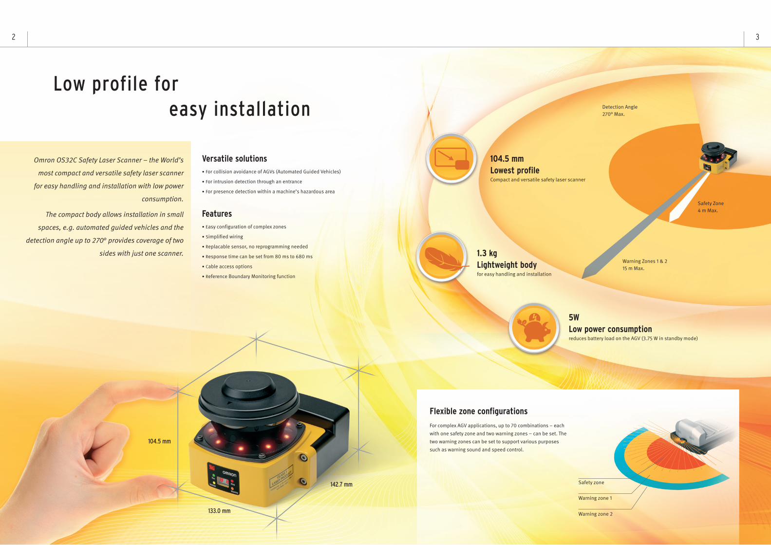
Omron OS32C Safety Laser Scanner – the World’s
most compact and versatile safety laser scanner
for easy handling and installation with low power
consumption.
The compact body allows installation in small
spaces, e.g. automated guided vehicles and the
detection angle up to 270° provides coverage of two
sides with just one scanner.
Versatile solutions• For collision avoidance of AGVs (Automated Guided Vehicles)
• For intrusion detection through an entrance
• For presence detection within a machine’s hazardous area
Features• Easy configuration of complex zones
• Simplified wiring
• Replacable sensor, no reprogramming needed
• Response time can be set from 80 ms to 680 ms
• Cable access options
• Reference Boundary Monitoring function
Low profile foreasy installation
104.5 mm
133.0 mm
142.7 mm
1.3 kgLightweight bodyfor easy handling and installation
104.5 mmLowest profileCompact and versatile safety laser scanner
5WLow power consumptionreduces battery load on the AGV (3.75 W in standby mode)
For complex AGV applications, up to 70 combinations – each
with one safety zone and two warning zones – can be set. The
two warning zones can be set to support various purposes
such as warning sound and speed control.
Flexible zone configurations
Safety zone
Warning zone 1
Warning zone 2
Safety Zone4 m Max.
Detection Angle270° Max.
Warning Zones 1 & 215 m Max.
54
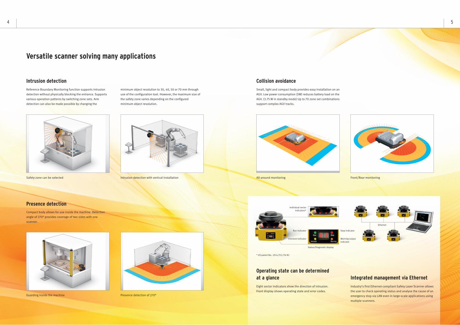
Versatile scanner solving many applications
Small, light and compact body provides easy installation on an
AGV. Low power consumption (5W) reduces battery load on the
AGV. (3.75 W in standby mode) Up to 70 zone set combinations
support complex AGV tracks.
Collision avoidance
Front/Rear monitoringAll-around monitoring
Compact body allows for use inside the machine. Detection
angle of 270° provides coverage of two sides with one
scanner.
Presence detection
Presence detection of 270°Guarding inside the machine
Reference Boundary Monitoring function supports intrusion
detection without physically blocking the entrance. Supports
various operation patterns by switching zone sets. Arm
detection can also be made possible by changing the
minimum object resolution to 30, 40, 50 or 70 mm through
use of the configuration tool. However, the maximum size of
the safety zone varies depending on the configured
minimum object resolution.
Intrusion detection
Safety zone can be selected Intrusion detection with vertical installation
Industry’s first Ethernet-compliant Safety Laser Scanner allows
the user to check operating status and analyse the cause of an
emergency stop via LAN even in large-scale applications using
multiple scanners.
Eight sector indicators show the direction of intrusion.
Front display shows operating state and error codes.
Integrated management via EthernetOperating state can be determinedat a glance
Run indicator
Individual sectorindicators*
Stop indicator
Ethernet
Status/Diagnostic display
* US patent No.: US 6,753,776 B2
Interlock indicator Warning output indicator
PTM (Pollution Tolerance Mode) enables a filter that allows the OS32C to distinguish between more than one detected reflection pulses.Ignoring small reflection pulses which could be caused by airborne dust or other contaminants in the safety zone.This function prevents nuisance machine stops due to dust.
Reflection pulseSmall reflection pulse
Referenceobject such
as guard
or pollution
The OS32C determines the safety zone is clear by detectinga reference object reflection pulse and does not stop the machine.
tectingthe machine. The size of a reflection pulse is distinguished
through the filter, and a small pollutionreflection pulse is ignored.
Reflection pulse
Referenceobject such
as guardNo reflection pulse returns from the reference object due to aninterruption by a human body. The OS32C stops the machine bydetecting an intrusion (human body) in the safety zone.
No reflection pulse returnsfrom the reference object.
Human body
Reducing Erroneous Detections in Safety Zone
76
Omron STI’s innovative I/O method requires fewer inputs
when configuring multiple zones. Only 4 inputs are required to
select from 6 zone sets. If all 8 inputs are used, up to 70 zone
sets are available.
Simplified wiring
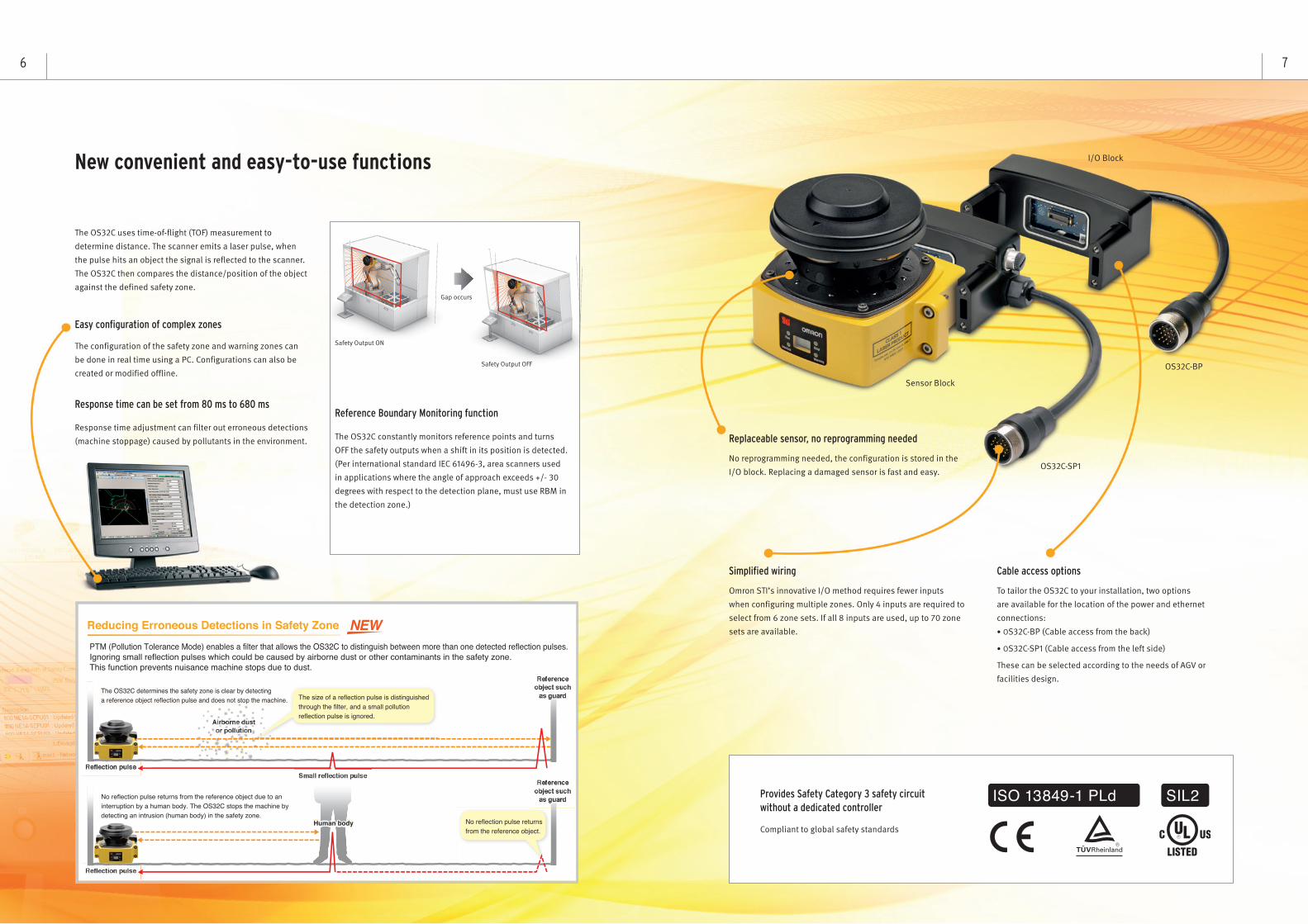
No reprogramming needed, the configuration is stored in the
I/O block. Replacing a damaged sensor is fast and easy.
The OS32C uses time-of-flight (TOF) measurement to
determine distance. The scanner emits a laser pulse, when
the pulse hits an object the signal is reflected to the scanner.
The OS32C then compares the distance/position of the object
against the defined safety zone.
Compliant to global safety standards
The OS32C constantly monitors reference points and turns
OFF the safety outputs when a shift in its position is detected.
(Per international standard IEC 61496-3, area scanners used
in applications where the angle of approach exceeds +/- 30
degrees with respect to the detection plane, must use RBM in
the detection zone.)
Replaceable sensor, no reprogramming needed
Provides Safety Category 3 safety circuitwithout a dedicated controller
Reference Boundary Monitoring function
Cable access options
To tailor the OS32C to your installation, two options
are available for the location of the power and ethernet
connections:
• OS32C-BP (Cable access from the back)
• OS32C-SP1 (Cable access from the left side)
These can be selected according to the needs of AGV or
facilities design.
OS32C-SP1
Sensor Block
I/O Block
OS32C-BP
Safety Output ON
Safety Output OFF
Gap occurs
Response time adjustment can filter out erroneous detections
(machine stoppage) caused by pollutants in the environment.
Response time can be set from 80 ms to 680 ms
The configuration of the safety zone and warning zones can
be done in real time using a PC. Configurations can also be
created or modified offline.
Easy configuration of complex zones
New convenient and easy-to-use functions
8
OS32C Safety sensors
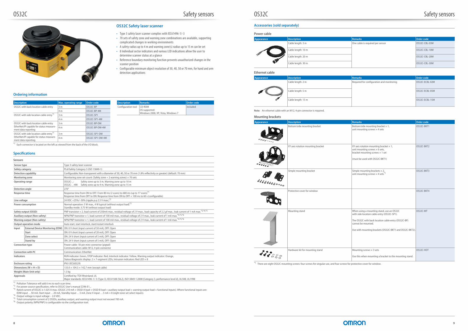
OS32C Safety laser scanner
• Type 3 safety laser scanner complies with IEC61496-1/-3• 70 sets of safety zone and warning zone combinations are available, supporting
complicated changes in working environments• A safety radius up to 4 m and warning zone(s) radius up to 15 m can be set• 8 Individual sector indicators and various LED indications allow the user to
determine scanner status at a glance• Reference boundary monitoring function prevents unauthorized changes in the
scanner position• Configurable minimum object resolution of 30, 40, 50 or 70 mm, for hand and arm
detection applications
Ordering information
Specifications
Sensors
Description Max. operating range Order code
OS32C with back location cable entry 3 m OS32C-BP
4 m OS32C-BP-4M
OS32C with side location cable entry*1
*1 Each connector is located on the left as viewed from the back of the I/O block.
3 m OS32C-SP1
4 m OS32C-SP1-4M
OS32C with back location cable entryEtherNet/IP capable for status measure-ment data reporting
3 m OS32C-BP-DM
4 m OS32C-BP-DM-4M
OS32C with side location cable entry*1
EtherNet/IP capable for status measure-ment data reporting
3 m OS32C-SP1-DM
4 m OS32C-SP1-DM-4M
Description Remarks Order code
Configuration tool CD-ROMOS supported:Windows 2000, XP, Vista, Windows 7
included
Sensor type Type 3 safety laser scanner
Safety category PLd/Safety Category 3 (ISO 13849-1)
Detection capability Configurable; Non-transparent with a diameter of 30, 40, 50 or 70 mm (1.8% reflectivity or greater) (default: 70 mm)
Monitoring zone Monitoring zone set count: (Safety zone + 2 warning zones) × 70 sets
Operating range OS32C-_: Safety zone up to 3 m, Warning zone up to 10 mOS32C-_-4M: Safety zone up to 4 m, Warning zone up to 15 m
Detection angle 270°
Response time Response time from ON to OFF: From 80 ms (2 scans) to 680 ms (up to 17 scans)*1
Response time from OFF to ON: Response time from ON to OFF + 100 ms to 60 s (configurable)
*1 Pollution Tolerance will add 6 ms to each scan time.
Line voltage 24 VDC +25%/–30% (ripple p-p 2.5 V max.)*2
*2 For power source specification, refer to OS32C User‘s manual Z296-E1...
Power consumption Normal operation: 5 W max., 4 W typical (without output load)*3
Standby mode: 3.75 W (without output load)
*3 Rated current of OS32C is 1.025 A max. (OS32C 210 mA + OSSD A load + OSSD B load + auxiliary output load + warning output load + functional Inputs). Where functional inputs are: EDM input …50 mA, Start input …20 mA, Standby input …5 mA, Zone X input …5 mA × 8 (eight zone set select inputs).
Safety output (OSSD) PNP transistor × 2, load current of 250mA max., residual voltage of 2 V max., load capacity of 2.2 μf max., leak current of 1 mA max.*3,*4,*5
*4 Output voltage is input voltage – 2.0 VDC.*5 Total consumption current of 2 OSSDs, auxiliary output, and warning output must not exceed 700 mA.
Auxiliary output (Non-safety) NPN/PNP transistor × 1, load current of 100 mA max., residual voltage of 2 V max., leak current of 1 mA max.*4,*5,*6
*6 Output polarity (NPN/PNP) is configurable via the configuration tool.
Warning output (Non-safety) NPN/PNP transistor × 1, load current of 100 mA max., residual voltage of 2 V max., leak current of 1 mA max.*4,*5,*6
Output operation mode Auto start, start interlock, start/restart interlock
Input External Device Monitoring (EDM) ON: 0 V short (input current of 50 mA), OFF: Open
Start ON: 0 V short (input current of 20 mA), OFF: Open
Zone select ON: 24 V short (input current of 5 mA), OFF: Open
Stand-by ON: 24 V short (input current of 5 mA), OFF: Open
Connection type Power cable: 18-pin mini-connector (pigtail)Communication cable: M12, 4-pin connector
Connection with PC Communication: EtherNet
Indicators RUN indicator: Green, STOP indicator: Red, Interlock indicator: Yellow, Warning output indicator: Orange, Status/diagnostic display: 2 × 7-segment LEDs, Intrusion indicators: Red LED × 8
Enclosure rating IP65 (IEC60529)
Dimensions (W × H × D) 133.0 × 104.5 × 142.7 mm (except cable)
Weight (Main Unit only) 1.3 kg
Approvals Certified by: TÜV Rheinland, ULMajor standards: IEC61496-1/-3 (Type 3), IEC61508 (SIL2), ISO13849-1:2008 (Category 3, performance level d), UL508, UL1998
OS32C_tecPart_rev04.fm Seite 8 Donnerstag, 2. Oktober 2014 9:36 09
OS32C Safety sensors
9
Accessories (sold separately)
Power cable
Ethernet cable
Note: An ethernet cable with an M12, 4-pin connector is required.
Mounting brackets
Appearance Description Remarks Order code
Cable length: 3 m One cable is required per sensor OS32C-CBL-03M
Cable length: 10 m OS32C-CBL-10M
Cable length: 20 m OS32C-CBL-20M
Cable length: 30 m OS32C-CBL-30M
Appearance Description Remarks Order code
Cable length: 2 m Required for configuration and monitoring OS32C-ECBL-02M
Cable length: 5 m OS32C-ECBL-05M
Cable length: 15 m OS32C-ECBL-15M
Appearance Description Remarks Order code
Bottom/side mounting bracket Bottom/side mounting bracket × 1,unit mounting screws × 4 sets
OS32C-BKT1
XY axis rotation mounting bracket XY axis rotation mounting bracket × 1,unit mounting screws × 6 sets,bracket mounting screws × 1 set
(must be used with OS32C-BKT1)
OS32C-BKT2
Simple mounting bracket Simple mounting brackets × 2,unit mounting screws × 4 sets*1
*1 There are eight OS32C mounting screws: four screws for singular use, and four screws for protective cover for window.
OS32C-BKT3
Protective cover for window OS32C-BKT4
Mounting stand When using a mounting stand, use an OS32C with side location cable entry (OS32C-SP1).
The OS32C with back location cable entry (OS32C-BP) cannot be mounted.
Use with mounting brackets (OS32C-BKT1 and OS32C-BKT2).
OS32C-MT
Hardware kit for mounting stand Mounting screws × 3 sets
Use this when mounting a bracket to the mounting stand.
OS32C-HDT
OS32C_tecPart_rev04.fm Seite 9 Donnerstag, 2. Oktober 2014 9:36 09

OS32C Safety sensors
10
Miscellaneous
Connection
Basic connection with single OS32C unit Category 3, performance level d (ISO13849-1)
Appearance Description Remarks Order code
Scan window Spare for replacement OS32C-WIN-KT
Sensor block without I/O blockMax. operating range: 3 m
Spare for replacement OS32C-SN
Sensor block without I/O blockMax. operating range: 4 m
OS32C-SN-4M
Sensor block without I/O block for EtherNet/IPMax. operating range: 3 m
Spare replacement for EtherNet/IP OS32C-SN-DM
Sensor block without I/O block for EtherNet/IPMax. operating range: 4 m
OS32C-SN-DM-4M
I/O block With cable access from the back
Spare for replacement OS32C-CBBP
With cable access from the left side
Spare for replacement OS32C-CBSP1
Window cleaning kit, anti-static cleaner Accessory WIN-CLN-KT
24 VDC (White)
0 VDC (Brown)
Standby input (Violet)
Zone select 1 (Orange/White)
Zone select 2 (Orange/Black)
Zone select 3 (Gray)
Zone select 4 (Pink)
Zone select 5 (White/Black)
Start (Black)
Auxiliary output (Blue)
Warning output (Red/Black)
EDM (Brown/White)
Safety output B (Yellow)
Safety output A (Red)
Zone select 6 (Tan)
Zone select 7 (Orange)
Zone select 8 (Blue/White)
Functional earth (Green)
ED1
ED2*1
*1
*2
S2
S3
S2
S1*3
*4
*4
S2
*4
S2
*4
S2
*4
*4
*4
*4
S2
S2
S2
0V
E1
+24V
PE
ED1 ED2
M1
ED1
ED2
S1 : Start inputS2 : Zone select switchS3 : Standby switchED1, ED2: Forced guided relayM1 : 3-Phase motorE1 : 24 VDC Power
OS32C configuration– External Device Monitoring enabled– Start/restart interlock
*1. External devices (ED1, ED2) are forced guide relays. (G7Z, G7SA, G7S, etc)*2. If the External Device Monitoring is not used, connect brown/white wires to 0 V, and then turn OFF the
External Device Monitoring with the configuration software.*3. Use NC-contact for a start input.*4. For zone select switch setting, refer to OS32C Series user's manual.Note: This wiring example is for category 3.
OS32C_tecPart_rev04.fm Seite 10 Donnerstag, 2. Oktober 2014 9:36 09
OS32C Safety sensors
11
Dimensions
OS32C with back location cable entry - OS32C-BP/OS32C-BP-DM
OS32C with side location cable entry - OS32C-SP1/OS32C-SP1-DM
158.3 [6.24]
90.4 [3.56]
Ethernet connectorwith M12 cap plug
Window
Dust detection
Ethernet cable not shown
Ethernetcable
I/O cable
I/O cable
I/O block
Sensor head
140.4 [5.53]
100.0 [3.94]
32.8 [1.29]
50.9 [2.01]
104.3 [4.11]
133.0 [5.24]
M5 x 0.8,DEPTH 9.0 [0.35]MAX (x4)
41.4 [1.63]MTG holes
6.0 [0.24]
57.0 [2.25]
50.0 [1.97]
27.7 [1.09]
104.5 [4.12]67.0 [2.64]Scan plane
2.0, 3.0, 10.0, 20.0, or 30.0 Meters
30.0 [1.18] dia. OD
102.9 [4.05]
I/O cable assy
270 (10.63)
121.0 [4.77]MTG holes
142.7 [5.62]
88.1 [3.47]
71.5 [2.82]
71.3 [2.81](min)
Back view
Bottom view
Side viewFront view
Top view
Ethernetcable
Window
Dust detection
I/O block
Sensor head
I/O cable
I/O cable
30.0 [1.18] dia. OD
2.0, 3.0, 10.0, 20.0, or 30.0 Meters
18.2 [0.72]39.0 [1.54]
25.0 [0.99]
104.3 [4.11]
90.4 [3.56]
67.0 [2.64]Scan plane
M5 x 0.8,DEPTH 9.0 [0.35] MAX (x4)
121.0 [4.77]MTG holes
41.4 [1.63]MTG holes
133.0 [5.24] 70.8 [2.79]
140.4 [5.53]
100.0 [3.94]
104.5 [4.12]32.8 [1.29]
57.0 [2.25]
6.0 [0.24] 50.4 [1.99]
142.7 [5.62]
88.2 [3.47]71.5 [2.82]
270
[10.
63]
102.9 [4.05]
I/O cable assy
Back view
Bottom view
Side viewFront view
Top view
Ethernet cable
OS32C_tecPart_rev04.fm Seite 11 Donnerstag, 2. Oktober 2014 9:36 09
Although we strive for perfection, Omron Europe BV and/or its subsidiary and affiliated companies do not warrant or make any representations regarding the correctness or completeness of the information described in this document. We reserve the right to make any changes at any time without prior notice.CD_EN-INT-03+OS32C+Brochure
Would you like to know more?
OMRON EUROPE B.V.
+31 (0) 23 568 13 00
industrial.omron.eu
Stay in touch
omron.me/socialmedia_eu
Austria Tel: +43 (0) 2236 377 800 industrial.omron.at
Belgium Tel: +32 (0) 2 466 24 80 industrial.omron.be
Czech Republic Tel: +420 234 602 602 industrial.omron.cz
Denmark Tel: +45 43 44 00 11 industrial.omron.dk
Finland Tel: +358 (0) 207 464 200industrial.omron.fi
France Tel: +33 (0) 1 56 63 70 00industrial.omron.fr
Germany Tel: +49 (0) 2173 680 00 industrial.omron.de
Hungary Tel: +36 1 399 30 50 industrial.omron.hu
Italy Tel: +39 02 326 81 industrial.omron.it
Netherlands Tel: +31 (0) 23 568 11 00 industrial.omron.nl
Norway Tel: +47 (0) 22 65 75 00 industrial.omron.no
Poland Tel: +48 22 458 66 66 industrial.omron.pl
Portugal Tel: +351 21 942 94 00 industrial.omron.pt
Russia Tel: +7 495 648 94 50 industrial.omron.ru
South AfricaTel: +27 (0)11 579 2600 industrial.omron.co.za
Spain Tel: +34 902 100 221 industrial.omron.es
Sweden Tel: +46 (0) 8 632 35 00 industrial.omron.se
Switzerland Tel: +41 (0) 41 748 13 13 industrial.omron.ch
Turkey Tel: +90 212 467 30 00 industrial.omron.com.tr
United Kingdom Tel: +44 (0) 1908 258 258 industrial.omron.co.uk
More Omron representatives industrial.omron.eu