sae-produkt-katalog 2009 · mounting table/magnetic table 200 x 100 mm medium pulsing current max....
TRANSCRIPT

SAE-PRODUKT-KATALOG 2009
Funkenerosions-TechnologieSpark Erosion Technology
Tecnologia dell’elettroerosioneТЕХНОЛОГИЯ ИСКРОВОЙ ЭРОЗИИ
SAE CATALOGUE OF PRODUCTS 2009CATALOGO PRODOTTI SAE 2009САЕ КАТАЛОГ ПРОДУКЦИИ 2009

SAE 2
Seite
SAE-Funkenerosionsmaschine 4/5
SAE-Grundausrüstung 6/7
SAE-Erodierzubehör 8/9
Elektroden für EM / CrCoMo / Titan 10/11
Friktionsstifte / Laser- und Schweißmaterial 12/13
Teleskopierende Doppelkronenmit einstellbarer Friktion 14/15
Zahnersatz mit Funkenerosionsgeschieben /Verarbeitungsanleitung Individuelle Geschiebe 16/17
SAE-T-Geschiebe 18/19
SAE-Spezi-T-Geschiebe 20/21
Chronologischer Ablauf einer T-Geschiebeerosion 22/23
SAE-Spezi-T-Geschiebe-Einbauanleitung 24/25
T-Geschiebe-Multi-Con 26/27
Doppel-T-Geschiebe 28/29
SAE-Reitergeschiebe 30/31
SAE-Reitergeschiebe-Einbauanleitung 32/33
Kunststoffprofi le / Konuszapfen / Diamantpolierpasten 34/35
SAE-Modell-Zentriersystem 36/37
Ergebnis der Vergleichsstudie in der QZ 03/2004Implantatmodelle mit konstanter Formstabilität 38/39
Präzisionsmodellmaterial 40/41
SAE-Präzisionsgusssystem für Kronen, Brücken und Einstückmodellguss 42/43
OKTA-Sil / Dubliersystem 44/45
SAE-Invest M2 / Oktagonküvette 46/47
Metallprüfmodell / Legierungen 48/49
Dosierspritze / Dosierspender / Modellentspanner /Haftvermittler / Aktivierungsinstrumente 50/51
Fräser 52/53
Zertifi kate 54/55
Telefonische BestellungMontag bis Freitag 8 bis 17 UhrTelefon (0471) 984 87-45 · Telefax (0471) 984 87-44
[email protected] · www.sae-dental.de
Inhalt Contents
Page
SAE Spark Erosion Machine 4/5
SAE Basic Equipment 6/7
SAE Erosion Accessories 8/9
Electrodes for Noble/Base Alloys / Titanium 10/11
Friction Pins / Laser and Welding Material 12/13
Telescopic Double Crowns with Controlled Friction 14/15
Dentures with Spark Erosion Attachments / Instructions Individual Attachments 16/17
SAE T Attachment 18/19
SAE Special T Attachment 20/21
Chronological Development of a T Attachment Erosion 22/23
Instructions SAE Special T Attachment 24/25
T Attachment Multi-Con 26/27
Dovetail Attachment 28/29
SAE Interlock Attachment 30/31
Instructions SAE Interlock Attachment 32/33
Plastic Profi les / Matrixes / Diamond Polishing Pastes 34/35
SAE Centering System 36/37
Result of the Comparative Study in QDT 03/2004Implant Models with Constant Form Stability 38/39
Precision Model Material 40/41
SAE Precision Casting System for Crowns/Bridges and One Cast 42/43
OKTA-Sil / Duplicating System 44/45
SAE Invest M2 / Duplication Mold 46/47
Metal Testing Cast / Alloys 48/49
Syringe / Measuring Dispenser / Model Tension Release / Bonding Agent / Activating Instruments 50/51
Burs 52/53
Certifi cates 54/55
Order by PhoneMonday till Friday 8 a.m. till 5 p.m.Telephone 00 49 / 47 19 84 87 - 45 · Fax 00 49 / 47 19 84 87 - 44
[email protected] · www.sae-dental.de

SAE 3
Indice Содержание
Pagina
Macchina di elettroerosione SAE 4/5
Attrezzatura di base SAE e banco di supporto 6/7
Accessori per elettroerosione SAE 8/9
Elettrodi per EM / CrCoMo / Titanio 10/11
Perni di frizione / Materiale laser e di saldatura 12/13
Corone doppie ibride con perni di frizione 14/15
Protesi dentaria con attacchi in elettroerosione / Istruzioni per la realizzazione di perni frizionanti 16/17
Attacco SAE-T 18/19
Attacco SAE-Spezi-T 20/21
Cronologia dell’erosione di un attacco T 22/23
Istruzioni per il montaggio dell’attacco SAE-Spezi T 24/25
Attacco T-Multi Con 26/27
Attacco doppia T (giuntore per protesi fi ssa) 28/29
Attacco Reiter SAE (attacco in tefl on) 30/31
Istruzioni per il montaggio dell’attacco Reiter SAE 32/33
Preformati calcinabili / Preformati calcinabili conici/ Paste diamantate per lucidare 34/35
Sistema di rimontaggio modello SAE 36/37
Risultato dello studio comparato in QZ 03/2004 Impianti con costante stabilità di forma 38/39
Materiale per modelli di precisione 40/41
Riposizionatore di corone, ponti o abutment singoli multipli per la realizzazione di piattelli per il frenaggio 42/43
OKTA-Sil / Sistema di duplicazione 44/45
SAE-Rivestimento M2/ Couvette ottagonale 46/47
Modello di prova in metallo per verifi ca espansione / Leghe 48/49
Siringa di dosaggio / Dispenser dosaggio / Riduttore di tensione /Colla per preformati/ Strumenti di attivazione 50/51
Frese e lame 52/53
Certifi cazioni 54/55
Страница
САЕ Искроэрозионная машина 4/5
САЕ Основное оснащение 6/7
САЕ Комплектующие для эрозии 8/9
Электроды для БМ / CrCoMo / Титан 10/11
Фрикционные штифты / Лазерный и сварочный материал 12/13
Телескопические двойные коронкидля регулируемой фрикции 14/15
Зубной протез с фрикционными аттачментами / 16/17Инструкция пользователя индивидуальных аттачментов
САЕ Т-аттачменты 18/19
САЕ Специ-Т-аттачменты 20/21
Хронологическая последовательность эрозии Т-аттачмента 22/23
САЕ Инструкция по монтажу Специ-Т-аттачмента 24/25
Т-аттачмент Multi-Con 26/27
Двойной Т-аттачмент 28/29
САЕ Рейтерный аттачмент 30/31
САЕ Инструкция по монтажу САЕ рейтерного аттачмента 32/33
Пластмассовые профили / Конусные цапфы /Алмазные полировальные пасты 34/35
САЕ Система центрования модели 36/37
Результат сравнительного исследования в QZ 03/2004Модели на имплантатах с постоянной прочностью формы 38/39
Прецизионный модельный материал 40/41
САЕ Прецизионная система литья коронок/мостови цельнолитых моделей 42/43
Оkta-Sil / Система дублирования 44/45
САЕ-Invest M2 / Восьмигранные кюветки 46/47
Металлическая контрольная модель / Сплавы 48/49
Шприц-дозатор / Донор-дозатор / Декомпрессор модели /Клей / Активирующие инструменты 50/51
Фрезы 52/53
Сертификаты 54/55
AUROTRE SRL / BRESCIA
Ordinazione per telefonoDal lunedì al venerdì dalle ore 8.30 alle ore 18.30Telefono 030-3544806 – fax 030-3532617
САЕ ДЕНТАЛЬ ФЕРТРИБС ГМБХ– ИНТЕРНАЦИОНАЛЬ –Лангенер Ландштрассе 173 · 27580 Бремехафен / ГерманияЗаказ по телефонуС понедельника до пятницы с 8 до 17 часовТелефон 8 1049 471 984 87-45 · Телефакс 8 1049 471 984 [email protected] · www.sae-dental.de
«Зуботехническая мастерская»Улица Гоголя, 36620151 Екатеринбург / РоссияЗаказ по телефону:С понедельника по пятницу с 8 до 17 часовТелефон: / Факс: (343) 3 55 32 71Е-майл: [email protected]

SAE 4
SAE Spark Erosion Machine EDM 2005 | Macchina di elettroerosione SAE EDM 2005 |
SAE-Funkenerosionsmaschine EDM 2005
Spezifikation / Specivication / Specifiche tecniche / СПЕЦИФИКАЦИЯAufspannfläche/Magnettisch 200 x 100 mm Mittlerer Impulsstrom max. 12 AMounting table/magnetic table 200 x 100 mm Medium pulsing current max. 12 ASuperficie di fissaggio/banco magnetico 200 x 100 mm Corrente media ad impulsi max. 12 AКрепёжная плита / Магнитный стол 200 х 100 мм Средний импульсный ток макс. 12 а
Längsverstellung, X-Achse 150 mm Höchster Impulsstrom max. 24 ALongitudinal adjustment, x axis 150 mm Highest pulsing current max. 24 ASpostamento longitudinale, asse X 150 mm Corrente max. ad impulsi max. 24 AПродольная регулировка по оси Х 150 мм Макс. импульсный ток макс. 24 а
Querverstellung, Y-Achse 100 mm Anschlussleistung 1,5 kVACross adjustment, Y axis 100 mm Connection 1,5 kVASpostamento trasversale, asse Y 100 mm Potenza assorbita 1,5 kVAПоперечная регулировка по оси Y 100 мм Присоединяемая мощность 1,5 ква
Größter Abstand Tisch/Pinole 240 mm Anschlussspannung 220 VMaximum space table/spindle sleeve 240 mm Connecting stress 220 VDistanza massima asse verticale Z 240 mm Tensione di rete 220 VМаксимальное расстояние стол/пиноль 240 мм Присоединяемое напряжение 220 в
Durchgehender Erodierhub 220 mm Frequenz 50 – 60 HzInternal erosion stroke 220 mm Frequency 50 – 60 HzDistanza massima di erosione 220 mm Frequenza 50 – 60 HzПроходящий эрозионный ход 220 мм Частота 50 - 60 гц
Inhalt des Dielektrikumsystems 45 l Gewicht 180 kg kpl.Contents of the dielectric fluid system 45 l Weight 180 kg cpl.Capacità serbatoio olio dielettrico 45 l Peso 180 kg compl.Содержание системы диэлектрика 45 л Вес 180 кг компл
Drehspindel 0-500 U.p.M 3-Achsen-Digitalanzeige / LCD-DisplayRotating coil 0-500 U.p.M 3 axis display / LCD displayVelocità rotazione mandrino 0-500 giri/min Visualizzazione digitale 3 assi / Display LCDВращающийся винт 0 - 500 об.в мин. Цифровая индикация 3 осей / LCD-дисплей
Füllhöhe Arbeitsbehälter 175 mmFilling height working container 175 mmLivello olio dielettrico nella vasca di lavoro 175 mmВысота наполнения раб. сосуда 175 мм

SAE 5
Improved Performances:Spark Erosion MachineEDM 2005• New digital generator
technology
• Modernized processor controlled unit
• Technology data memory Call up by product code
• Z axis unit
• Multi function display with error display
• Minimization of the surface rough depth
• With PCI contact – control by laptop possible
• Faster filling of tank
• Z axis “touch down zero point adjustment”
• Individual parameter adjustments possible
Usable for:• SAE T attachment
• SAE double T attachment
• SAE interlock attachment
• SAE swivel-latch attachment
• SAE swivel-latch attachment ‘95
• SAE module latch
• SAE pin attachment
• Friction pins
• Passivation of implant frameworks
SAE Spark Erosion Machine10-1105 SAE Spark
erosion machineEDM 2005 new
Migliorie di performance:Macchina di elettroerosione EDM 2005• Generatore di nuova
tecnologia
• Unità di comando mo-dernizzata controllata da microprocessore
• Memoria dati con pro-grammi preimpostati
• Comando separato asse Z
• Display multifunzione con visualizzazione errori
• Riduzione al minimo del-la rugosità superficiale
• Ingresso PCI – possibi-lità di comando tramite portatile
• Riempimento più rapido della vasca di lavoro
• Asse Z “Impostazione punto zero touch-down”
• Possibilità di imposta-zione individuale dei parametri
Può essere usata per:• Attacco SAE-T
• Attacco SAE doppia T
• Attacco Reiter SAE
• Chiavistelli orientabili SAE
• Chiavistelli orientabili SAE ‘95
• Chiavistelli SAE a modulo
• Chiavistelli a perno (bot-tone) SAE
• Perni di frizione
• Passivazione delle strut-ture implantari
Macchina di elettroerosione SAE10-1105 Macchina di
elettroerosione SAE EDM 2005 – Novità
Искроэрозионная машинаEDM 2005 с усовершенствованной мощностью:
• новая технология генератора
• переоснащённый пульт управления
• технология архивации данных
• измерение по оси Z
• многофункциональный дисплей с индикацией ошибок
• уменьшение шероховатой поверхности
• ввод для ПК – возможно управление через портативный компьютер
• ускоренное наполнение бассейна
• «Touch-down» обнуление позиции по оси Z
• возможность индивидуального введения параметров
Используется для:
• САЕ Т-аттачменты
• САЕ двойные Т-аттачменты
• САЕ рейтерные аттачменты
• САЕ поворотные фиксаторы
• САЕ поворотные фиксаторы’95
• САЕ модульные фиксаторы
• САЕ штекерные фиксаторы
• Фрикционные штифты
• Припасовка структур на имплантатах
САЕ Искроэрозионная машина10-1105 САЕ Искроэрозионная
машинаEDM 2005, новая
САЕ Искроэрозионная машина EDM 2005
Verbesserte Leistungen:Funkenerosionsmaschine EDM 2005• Neue digitale
Generator technologie
• Modernisierte prozessor-gesteuerte Bedieneinheit
• Technologiedaten-speicher Aufruf über Produktkennung
• Z-Achsen-Einheit
• Multifunktionsdisplay mit Fehleranzeige
• Minimierung der Oberflächen rautiefe
• Mit PCI-Anschluss –Steuerung über Laptop möglich
• Schnellere Tankbefüllung
• Z-Achse „Touch-down-Nullpunkteinstellung“
• Individuelle Parameter-einstellungen möglich
Nutzbar für:• SAE-T-Geschiebe
• SAE-Doppel-T-Geschiebe
• SAE-Reitergeschiebe
• SAE-Schwenkriegel
• SAE-Schwenkriegel ’95
• SAE-Modulriegel
• SAE-Steckriegel
• Friktionsstifte
• Passivierung der Implantat strukturen
SAE-Funkenerosions-maschine10-1105 SAE-Funkenerosions-
maschine EDM 2005 neu

SAE 6
Erodier-Zubehör
Basic Equipment for Spark Erosion Machine SAE EDM 2005/2000 | Attrezzatura di base Основное оснащение для искроэрозионной установки SAE-EDM 2005 / 2000
1 2 3 4 5 6 7
89101112
13
14
14 15 14 + 15 16 17
Abb. 75%
Erodier-ZubehörAbb. 50%
Grundausstattung für SAE-EDM 2005 / 2000-Funkener
Schrankeinheit für EDM 2005 / 2000
18

SAE 7
Zubehör20-1028 14. Modellhalter
für EDM 2005 und EDM 200020-1031 15. Winkel für Modellhalter20-1018 16. Befestigungselemente
für Modell (1 Paar)30-1603 17. Klammer10-2220 Gummirondelle
0,5 – 2,5 mm für EDM 2005 und EDM 2000 (ohne Abbildung)
10-1007 Dielektrikum (ohne Abbildung)
30-1605 Buchsen für Elektroden-führung zu 30-1602 (ohne Abbildung)
Schrankeinheit10-2450 18. Schrankeinheit
per elettroerosione SAE-EDM 2005/2000 |
Erodier-Zubehör30-2600 1. Spannzangenhalter
zur Aufnahme der Spannzangen
Spannzangen zur Aufnahme der Kupfer-elektroden, Spannbereich 0,5-6,0 mm20-1201 2. Spannzange 1,0-0,5 mm20-1202 3. Spannzange 2,0-1,0 mm20-1203 4. Spannzange 3,0-2,0 mm20-1204 5. Spannzange 4,0-3,0 mm20-1205 6. Spannzange 5,0-4,0 mm20-1206 7. Spannzange 6,0-5,0 mm20-1029 8. Halter zum Aufnehmen der
Supra konstruktion beim Erodieren der Implantate
30-2610 9. Universal-ElektrodenhalterElektrodenhalter für alle T-Geschiebe-Erosionen
20-1032 10. Maschinenaufnahme für Zentriersystem, um exakte Nullposition in der Maschi-ne einstellen zu können
30-2630 11. Aufnahme für alle Riegel-Erosionen
30-2620 12. Tiefeneinstelllehre, um beim Nacherodieren die Originaltiefe einstellen zu können
30-1602 13. Elektrodenführung zum Erodieren der Riegelachse
30-1607 14. Winkelhalter Riegelachse
osionsanlage
Erosion Accessories 1. Chuck holder to receive chucks
Chucks to receive copperelectrodes, chuck capacity 0.5-6.0 mm 2. Chuck holder 1.0-0,5 mm 3. Chuck holder 2.0-1.0 mm 4. Chuck holder 3.0-2.0 mm 5. Chuck holder 4.0-3.0 mm 6. Chuck holder 5.0-4.0 mm 7. Chuck holder 6.0-5.0 mm 8. Holder to engage superstructure for erosive machining with implant abutments 9. Universal electrode holder electrode holder for all T attachment erosions 10. Holder for centering system to achieve exact 0 position in machine
11. Holder for all latch attachment erosions 12. Depth gauge to enable the adjustment of original depth for finishing erosive process 13. Electrode guide for latch axis 14. Angle holder latch axis
Accessories 14. Model mount for EDM 2005 and EDM 2000 15. Angled plate for model mount 16. Securing clamps for model (1 pair) 17. Clamp Rubber circulars 0.5 - 2.5 mm for EDM 2005 and EDM 2000 (not shown) Dielectric fluid (not shown) Sleeves for electrode guide for 30-1602 (not shown)
Cabinet 18. Cabinet
Комплектующие 14. Держатель модели для EDM 2005 и EDM 2000 15. Угол для зажима модели 16. Крепёжные элементы для модели (1 пара) 17. Скоба Резиновые рондели 0,5 – 2,5 мм для EDM 2005 и EDM 2000 (без рисунка) Диэлектрик (без рисунка) Втулки для направляющей электрода к 30-1602 (без рисунка)
Стол-шкаф 18. Стол-шкаф
Комплектующие для эрозии 1. Цанговый зажим для приёма цангиЦанги для приёма медных электродов,диапазон зажима 0,5 - 6,0 мм 2. Цанга 1,0-0,5 мм 3. Цанга 2,0-1,0 мм 4. Цанга 3,0-2,0 мм 5. Цанга 4,0-3,0 мм 6. Цанга 5,0-4,0 мм 7. Цанга 6,0-5,0 мм 8. Зажим для приёма супраконструкции при эрозии имплантатов 9. Универсальный зажим для электродов Зажим для электродов для всех эродируемых Т-аттачментов 10. Машинный зажим для центрирующей системы для установки точной нулевой позиции в машине 11. Зажим для всех эродируемых фиксаторов 12. Регулировочный глубиномер для установки заданной глубины при повторном эродировании 13. Направляющая электрода для эрозии оси фиксатора 14. Угловой держатель оси фиксатора
Accessori per l’erosione 1. Portapinze per alloggiamento pinze
Pinze per alloggiamento elettrodi di rame, campo di serraggio da 0,5 a 6,0 mm 2. Pinza 1,0 - 0,5 mm 3. Pinza 2,0 - 1,0 mm 4. Pinza 3,0 - 2,0 mm 5. Pinza 4,0 - 3,0 mm 6. Pinza 5,0 - 4,0 mm 7. Pinza 6,0 - 5,0 mm 8. Supporto per legare la sovrastruttura nell’erosione su impianti 9. Portaelettrodi universale Portaelettrodi per tutte le erosioni di attacchi T 10. Supporto per il riposizionamento dell’asse Z nei modelli di lavoro 11. Portaelettrodo per l’erosione dei chiavistelli 12. Calibro profondità
13. Centratore elettrodi per l’erosione dell’asse del chiavistello 14. Supporto angolare asse chiavistello
Accessori 14. Portamodello per EDM 2005 e EDM 2000 15. Squadra per portamodelli 16. Molle di fissaggio modelli (1 paio) 17. Molla per centratore dell’asse dei chiavistelli Rondella di gomma 0,5 – 2,5 mm per EDM 2005 e EDM 2000 (senza figura)
Olio dielettrico (senza figura)
Boccola in teflon per centratore di elettrodi 30-1602 (senza figura)
Banco di supporto 18. Banco di supporto

SAE 8
Accessories for Spark Erosion Machine SAE EDM 2005 / 2000 | Accessori per elettroeroКомплектующие для искроэрозионной установки САЕ EDM 2005 / 2000
Zubehör für SAE-EDM 2005 / 2000-Funkenerosionsanl
1
1
1
1
Geschiebeautomat
Blattelekrodenband
Elektrodenrichthilfe
1 + 22
Modellhalter mit WinkelAbb. 50%

SAE 9
sione SAE-EDM 2005 / 2000 |
age
Geschiebeautomat20-1022 1. Geschiebeautomat
zur Aufnahme von Elektrodenband zum gleichzeitigen Schlitzen der Stifte mit den Stärken 1,6 + 1,7 + 1,8, Schlitz stärke 0,11 mm
Blattelektrodenband20-1023 1. Blattelektrodenband
Kupfer Abmessung: Stärke 0,10 mm Breite 10 mm Länge 2000 mm für CrCoMo und Gold
20-1027 Blattelektrodenband Graphit (ohne Abb.) Abmessung: Stärke 0,10 mm Breite 10 mm Länge 45 mm für Titan
Elektrodenrichthilfe20-1024 1. Elektrodenrichthilfe zum
Zentrieren der runden Kupferelektroden in den Abmessungen 0,6 – 1,7 mm Øfür SAE-Funkenerosions-geräte aller Typen
Modellhalter mit Winkel20-1028 1. Modellhalter
für EDM 2005 und EDM 200020-1031 2. Winkel für Modellhalter
Attachment Automation 1. Attachment automation to receive band electrode for simultaneous slitting of pins with strengths 1.6 + 1.7 + 1.8, slitting strength 0.11 m
Band electrode 1. Band electrode Copper Measurements: Strength 0.10 mm Width 10 mm Length 2000 mm for base alloy and gold Band electrode Graphite (not shown) Measurements: Strength 0.10 mm Width 10 mm Length 45 mm for titanium
Electrode Guide 1. Electrode guide for centering round copper electrodes with measurements 0.6 – 1.7 mm Ø for SAE spark erosion units of all types
Model Mount with Angled Plate 1. Model mount for EDM 2005 and EDM 2000 2. Angled plate for model mount
Автомат замковых креплений 1. Автомат замковых креплений для приёма электродной ленты для одновременного надрезания штифтов, толщиной 1,6 + 1,7 + 1,8 Толщина разреза 0,11 мм
Лента плоских электродов 1. Лента плоских электродов Медь Размеры: Толщина 0,10 мм Ширина 10 мм Длина 2000 мм для CrCoMo и золота Лента плоских электродов Графит (без рисунка) Размеры: Толщина 0,10 мм Ширина 10 мм Длина 45 мм для титана
Направляющая электродов 1. Направляющая электродов для центровки круглых медных электродов, диаметром 0,6 – 1,7 мм для искроэрозионных приборов САЕ всех типов
Держатель модели с углом 1. Держатель модели для EDM 2005 и EDM 2000 2. Угол для держателя модели
Apparecchiatura tagliaperni 1. Apparecchiatura automatica per il taglio dei perni con spessore 1,6 + 1,7 + 1,8, spessore taglio 0,11 mm
Banda elettrodo tagliaperni 1. Banda elettrodo tagliaperni Rame Misure: Spessore 0,10 mm Larghezze 10 mm Lunghezza 2000 mm Per CrCoMo ed oro Banda elettrodo tagliaperni Grafite (senza figura) Misure: Spessore 0,10 mm Larghezza 10 mm Lunghezza 45 mm per il titanio
Strumento per il centraggio elettrodi 1. Strumento per il centraggio degli elettrodi di rame rotondi di 0,6 - 1,7 mm di Ø per le apparecchiature di elettroerosione SAE di tutti i tipi
Portamodello con squadra 1. Portamodello per EDM 2005 e EDM 2000 2. Squadra per portamodello

SAE 10
Consumption Materials SAE Electrodes | Materiali di consumo Elettrodi SAE | Расходн
Cu-Elektroden für EM/CrCoMo/Titan ab Ø 1,5Abb. 50%
Elektroden für TitanAbb. 50%
Verbrauchsmaterialien SAE-Elektroden

SAE 11
Für EM/CrCoMo/Titan ab Ø 1,530-1001 Cu.-Elektrode Ø 0,530-1002 Cu.-Elektrode Ø 0,630-1003 Cu.-Elektrode Ø 0,730-1004 Cu.-Elektrode Ø 0,830-1024 Cu.-Elektrode Ø 0,8530-1005 Cu.-Elektrode Ø 0,930-1006 Cu.-Elektrode Ø 1,030-1007 Cu.-Elektrode Ø 1,130-1008 Cu.-Elektrode Ø 1,230-1011 Cu.-Elektrode Ø 1,430-1012 Cu.-Elektrode Ø 1,530-1013 Cu.-Elektrode Ø 1,630-1014 Cu.-Elektrode Ø 1,730-1029 Cu.-Elektrode Ø 4,0
ые материалы САЕ-электроды
Für Titan30-1043 Elektrode Ø 0,8030-1041 Elektrode Ø 1,5030-1042 Elektrode Ø 1,60
For Noble/Base Alloys / Titanium from Ø 1,5 up Copper electrode Ø 0.5 Copper electrode Ø 0.6 Copper electrode Ø 0.7 Copper electrode Ø 0.8 Copper electrode Ø 0.85 Copper electrode Ø 0.9 Copper electrode Ø 1.0 Copper electrode Ø 1.1 Copper electrode Ø 1.2 Copper electrode Ø 1.4 Copper electrode Ø 1.5 Copper electrode Ø 1.6 Copper electrode Ø 1.7 Copper electrode Ø 4,0
For Titanium Electrode Ø 0.80 Electrode Ø 1.50 Electrode Ø 1.60
Для титана Электрод, Ø 0,80 Электрод, Ø 1,50 Электрод, Ø 1,60
Для БМ / CrCoMo /Титан с Ø 1,5 Электрод, медный, Ø 0,5 Электрод, медный, Ø 0,6 Электрод, медный, Ø 0,7 Электрод, медный, Ø 0,8 Электрод, медный, Ø 0,85 Электрод, медный, Ø 0,9 Электрод, медный, Ø 1,0 Электрод, медный, Ø 1,1 Электрод, медный, Ø 1,2 Электрод, медный, Ø 1,4 Электрод, медный, Ø 1,5 Электрод, медный, Ø 1,6 Электрод, медный, Ø 1,7 Электрод, медный, Ø 4,0
Per EM/CrCoMo/Titanio a partire dal Ø 1,5 Elettrodo Cu Ø 0,5 Elettrodo Cu Ø 0,6 Elettrodo Cu Ø 0,7 Elettrodo Cu Ø 0,8 Elettrodo Cu Ø 0,85 Elettrodo Cu Ø 0,9 Elettrodo Cu Ø 1,0 Elettrodo Cu Ø 1,1 Elettrodo Cu Ø 1,2 Elettrodo Cu Ø 1,4 Elettrodo Cu Ø 1,5 Elettrodo Cu Ø 1,6 Elettrodo Cu Ø 1,7 Elettrodo Cu Ø 4,0
Per il titanio Elettrodo Ø 0,80 Elettrodo Ø 1,50 Elettrodo Ø 1,60

SAE 12
Consumption Materials SAE Friction Pins | Materiali di consumo Perni di frizione SAE
Friktionsstifte CrCoMo (gezogen und geschliffen) – nickelfreiAbb. 50%
Abb. 50%
Abb. 30%
Friktionsstifte Titan / Titan Niob / Gold
Laser- und Schweißmaterial
1 2
Verbrauchsmaterialien SAE-Friktionsstifte
SAE 13
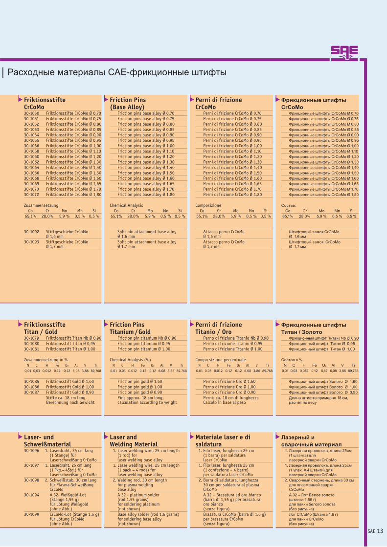
Friktionsstifte CrCoMo30-1050 Friktionsstifte CrCoMo Ø 0,7030-1051 Friktionsstifte CrCoMo Ø 0,7530-1052 Friktionsstifte CrCoMo Ø 0,8030-1053 Friktionsstifte CrCoMo Ø 0,8530-1054 Friktionsstifte CrCoMo Ø 0,9030-1055 Friktionsstifte CrCoMo Ø 0,9530-1056 Friktionsstifte CrCoMo Ø 1,0030-1058 Friktionsstifte CrCoMo Ø 1,1030-1060 Friktionsstifte CrCoMo Ø 1,2030-1062 Friktionsstifte CrCoMo Ø 1,3030-1064 Friktionsstifte CrCoMo Ø 1,4030-1066 Friktionsstifte CrCoMo Ø 1,5030-1068 Friktionsstifte CrCoMo Ø 1,6030-1069 Friktionsstifte CrCoMo Ø 1,6530-1070 Friktionsstifte CrCoMo Ø 1,7030-1072 Friktionsstifte CrCoMo Ø 1,80
Zusammensetzung Co Cr Mo Mn Si 65,1% 28,0% 5,9 % 0,5 % 0,5 %
30-1092 Stiftgeschiebe CrCoMo Ø 1,6 mm
30-1093 Stiftgeschiebe CrCoMo Ø 1,7 mm
| Расходные материалы САЕ-фрикционные штифты
Friktionsstifte Titan / Gold30-1079 Friktionsstift Titan Nb Ø 0,9030-1080 Friktionsstift Titan Ø 0,9530-1081 Friktionsstift Titan Ø 1,00
Zusammensetzung in % N C H Fe O2 Al V Ti 0,01 0,03 0,012 0,12 0,12 6,08 3,86 89,768
30-1085 Friktionsstift Gold Ø 1,6030-1086 Friktionsstift Gold Ø 1,0030-1087 Friktionsstift Gold Ø 0,90 Stifte ca. 18 cm lang,
Berechnung nach Gewicht
Laser- und Schweißmaterial30-1096 1. Laserdraht, 25 cm lang
(1 Stange) für Laserschweißung CrCoMo
30-1097 1. Laserdraht, 25 cm lang (1 Pkg.= 4Stg.) für Laserschweißung CrCoMo
30-1098 2. Schweißstab, 30 cm lang für Plasma-Schweißung CrCoMo
30-1094 A 32- Weißgold-Lot (Stange 1,55 g)für Lötung Weißgold (ohne Abb.)
30-1099 CrCoMo-Lot (Stange 1,6 g) für Lötung CrCoMo (ohne Abb.)
Friction Pins (Base Alloy) Friction pins base alloy Ø 0.70 Friction pins base alloy Ø 0.75 Friction pins base alloy Ø 0.80 Friction pins base alloy Ø 0.85 Friction pins base alloy Ø 0.90 Friction pins base alloy Ø 0.95 Friction pins base alloy Ø 1.00 Friction pins base alloy Ø 1.10 Friction pins base alloy Ø 1.20 Friction pins base alloy Ø 1.30 Friction pins base alloy Ø 1.40 Friction pins base alloy Ø 1.50 Friction pins base alloy Ø 1.60 Friction pins base alloy Ø 1.65 Friction pins base alloy Ø 1.70 Friction pins base alloy Ø 1,80
Chemical Analysis Co Cr Mo Mn Si 65.1% 28.0% 5.9 % 0.5 % 0.5 %
Split pin attachment base alloy Ø 1.6 mm Split pin attachment base alloy Ø 1.7 mm
Friction Pins Titanium / Gold Friction pin titanium Nb Ø 0.90 Friction pin titanium Ø 0.95 Friction pin titanium Ø 1.00
Chemical Analysis (%) N C H Fe O2 Al V Ti 0.01 0.03 0.012 0.12 0.12 6.08 3.86 89.768
Friction pin gold Ø 1.60 Friction pin gold Ø 1.00 Friction pin gold Ø 0.90 Pins approx. 18 cm long, calculation according to weight
Laser and Welding Material 1. Laser welding wire, 25 cm length (1 rod) for laser welding base alloy 1. Laser welding wire, 25 cm length (1 pack = 4 rods) for laser welding base alloy 2. Welding rod, 30 cm length for plasma welding base alloy A 32 - platinum solder (rod 1.55 grams) for soldering platinum (not shown) Base alloy solder (rod 1.6 grams) for soldering base alloy (not shown)
Лазерный исварочный материал 1. Лазерная проволока, длина 25см (1 штанга) для лазерной сварки CrCoMo 1. Лазерная проволока, длина 25см (1 упак. = 4 штанги) для лазерной сварки CrCoMo 2. Сварочный стержень, длина 30 см для плазменной сварки CrCoMo А 32 – Лот Белое золото (штанга 1,55 г) для пайки белого золота (без рисунка) Лот CrCoMo (Штанга 1,6 г) для пайки CrCoMo (без рисунка)
Фрикционные штифты CrCoMo Фрикционные штифты CrCoMo Ø 0,70 Фрикционные штифты CrCoMo Ø 0,75 Фрикционные штифты CrCoMo Ø 0,80 Фрикционные штифты CrCoMo Ø 0,85 Фрикционные штифты CrCoMo Ø 0,90 Фрикционные штифты CrCoMo Ø 0,95 Фрикционные штифты CrCoMo Ø 1,00 Фрикционные штифты CrCoMo Ø 1,10 Фрикционные штифты CrCoMo Ø 1,20 Фрикционные штифты CrCoMo Ø 1,30 Фрикционные штифты CrCoMo Ø 1,40 Фрикционные штифты CrCoMo Ø 1,50 Фрикционные штифты CrCoMo Ø 1,60 Фрикционные штифты CrCoMo Ø 1,65 Фрикционные штифты CrCoMo Ø 1,70 Фрикционные штифты CrCoMo Ø 1,80
Состав: Co Cr Mo Mn Si 65,1% 28,0% 5,9 % 0,5 % 0,5 %
Штифтовый замок CrCoMo Ø 1,6 мм Штифтовый замок CrCoMo Ø 1,7 мм
Фрикционные штифты Титан / Золото Фрикционный штифт Титан / Nb Ø 0,90 Фрикционный штифт Титан Ø 0,95 Фрикционный штифт Титан Ø 1,00
Состав в % N C H Fe O2 Al V Ti 0,01 0,03 0,012 0,12 0,12 6,08 3,86 89,768
Фрикционный штифт Золото Ø 1,60 Фрикционный штифт Золото Ø 1,00 Фрикционный штифт Золото Ø 0,90 Длина штифта примерно 18 см, расчёт по весу
Perni di frizione CrCoMo Perni di frizione CrCoMo Ø 0,70 Perni di frizione CrCoMo Ø 0,75 Perni di frizione CrCoMo Ø 0,80 Perni di frizione CrCoMo Ø 0,85 Perni di frizione CrCoMo Ø 0,90 Perni di frizione CrCoMo Ø 0,95 Perni di frizione CrCoMo Ø 1,00 Perni di frizione CrCoMo Ø 1,10 Perni di frizione CrCoMo Ø 1,20 Perni di frizione CrCoMo Ø 1,30 Perni di frizione CrCoMo Ø 1,40 Perni di frizione CrCoMo Ø 1,50 Perni di frizione CrCoMo Ø 1,60 Perni di frizione CrCoMo Ø 1,65 Perni di frizione CrCoMo Ø 1,70 Perni di frizione CrCoMo Ø 1,80
Composizione Co Cr Mo Mn Si 65.1% 28.0% 5.9 % 0.5 % 0.5 %
Attacco perno CrCoMo Ø 1,6 mm Attacco perno CrCoMo Ø 1,7 mm
Perni di frizione Titanio / Oro Perno di frizione Titanio Nb Ø 0,90 Perno di frizione Titanio Ø 0,95 Perno di frizione Titanio Ø 1,00
Compo sizione percentuale N C H Fe O2 Al V Ti 0.01 0.03 0.012 0.12 0.12 6.08 3.86 89.768
Perno di frizione Oro Ø 1,60 Perno di frizione Oro Ø 1,00 Perno di frizione Oro Ø 0,90 Perni: ca. 18 cm di lunghezza Calcolo in base al peso
Materiale laser e di saldatura 1. Filo laser, lunghezza 25 cm (1 barra) per saldatura laser CrCoMo 1. Filo laser, lunghezza 25 cm (1 confezione – 4 barre) per saldatura laser CrCoMo 2. Barra di saldatura, lunghezza 30 cm per saldatura al plasma CrCoMo A 32 – Brasatura ad oro bianco (barra di 1,55 g) per brasatura oro bianco (senza figura) Brasatura CrCoMo (barra di 1,6 g) per brasatura CrCoMo (senza figura)

SAE 14
Mit dem SAE-Funkenerosionsverfahren werden Passungenfür Friktionsstifte in Doppelkronen parallel erodiert.
Die nach der Erosion gesetzten Stifte haben einen Durchmesser von 0,8 bis 0,9 mm und sind mit deridentischen Legierung durch Laserschweißung mitdem Modellguss verbunden – lotfrei!
Bei den aus CrCoMo oder Titan gefertigten Doppelkronenwird auf den Konuswinkel verzichtet. Dadurch steht dergewonnene Platz bei der Doppelkrone mit 2° Neigungswinkelfür mehr Ästhetik bei der Keramik- oder Kunststoffverblendungzur Verfügung.
Die Langzeiterfahrung in der Verarbeitung von CrCoMoin Verbindung mit dem von SAE entwickelten Präzisions-gussverfahren schafft die Voraussetzung, bügelfreiebrückenartige Konstruktionen grazil und verwindungsfreianfertigen zu können.
Teleskopierende Doppelkronen mitaktivierbaren Friktionsstiften aus CrCoMo
SAE-TECHNOLOGIE – Biokompatibler Zahnersatz
Kontrollierte, gesteuerte Abzugskräfte beim teleskopierenden Zahnersatz im LangzeittestTest an der Hochschule Bremerhaven
Die Abzugskräfte sind bei den durch das SAE-Verfahren gefertigten teleskopierenden Doppelkronen auch bei steigendem Kaudruck konstant.
Der Testversuch zeigt, dass unabhängig von dem Aufpressdruck (Kaudruck) die Abzugskräfte gleichmäßig bei 7 Newton bleiben. Die friktive Haftung des Zahnersatzes im Munde des Prothesenträgers ist sicher und optimal gut.
Ein Verkeilen des Zahnersatzes beim Eingliedern oder ein Friktionsverlust wie beim konventionellen Zahnersatz mit Konuskronen wird durch die SAE-Technologie vermieden.

SAE 15
• hervorragender Tragekomfort durch grazile und leichte Ausführung
• natürlich ästhetische Wirkung durch plaquefreie Kompositverblendung-Cromasit
• beste Hygienefähigkeit durch leichtes Ein- und Ausgliedern durch den Patienten
• wirtschaftlich durch preiswerte Erweiterungs fähigkeit bis zur Vollprothese
oTV 11oTV 12
oTV 13E 14
E 15E 16E 17
21 TVo22 TVo
23 TVo24 E
25 E26 E27 E
Primärkronen mit auslaufender Stufe
Passgenauer spannungsfreier Einstückmodellguss nachdem SAE-System aus CrCoMo, lotfrei, biokompatibel
Teleskopierende Doppelkronen mit friktiverHaftung über eingeschweißte Friktionsstifte,
deren Passungen funkenerodiert sind
Friktionsstift
Erosionsrille
mit teleskopierenden Doppelkronenmit steuerbarer Friktionaus CrCoMo nickelfrei kompositverblendet
For the English version please visit: www.sae-dental.de
Per la versione italiana
invitiamo a visitare il sito:www.sae-dental.de
Пожалуйста, посетитерусскую версию на:
www.sae-dental.de

SAE 16
Distal an den Kronen sind individuelle Zapfengeschiebe angegossen, die einen Neigungswinkel von 2° Grad haben. In die funkenerodierten Rundpassungen sind jeweils buccal und lingual Friktionsstifte eingepasst und verschweißt.
Die Friktionsstifte geben dem Zahnersatz die notwendige friktive Haftung. Eine eventuell spätere Aktivierung der Stifte kann durch ein Aktivierungsinstrument (Bestell-Nr. 30-5003) leicht ausgeführt werden.
Die Friktionsstifte sind mittels Laserschweißung mit der Sekundärkonstruktion lotfrei verbunden.
E 47 E 46 E 45 E 44 KM 43 KM 42 KM 41
37 E 36 E 35 KM 34 KM 33 KM 32 KM 31 KM
oo
o
Geschiebe
Keramisch verblendete Kronen aus CrCoMo auf den Pfeilern 35-43(Verblockungsgeschiebe zwischen 42 und 43)
korrosionsfrei – biokompatibel
SAE-TECHNOLOGIE – Kombiniert festsitzend/herausneh
For the English version please visit: www.sae-dental.de
Пожалуйста, посетитерусскую версию на:
www.sae-dental.dePer la versione italiana
invitiamo a visitare il sito:www.sae-dental.de
SAE 17
mbarer Zahnersatz mit individuellen Geschieben
Verarbeitungsanleitung
1.
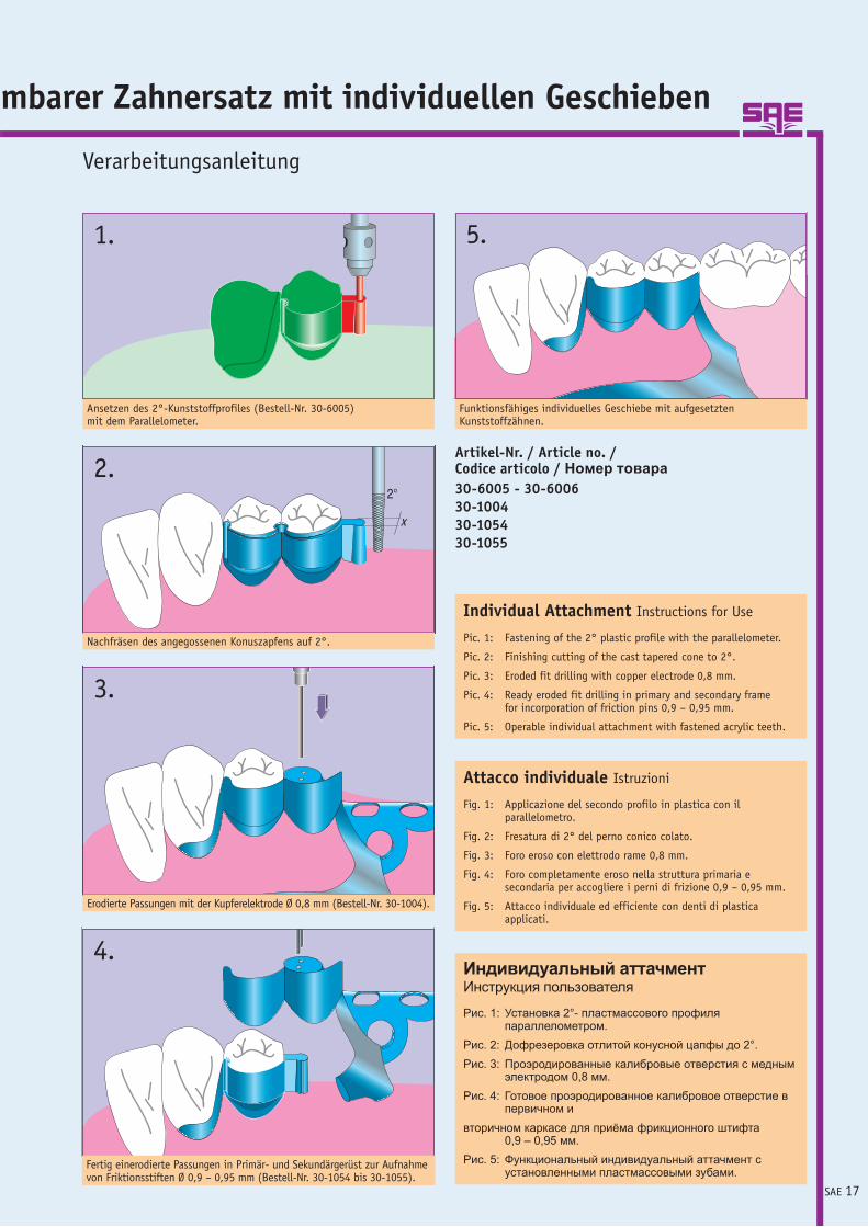
Ansetzen des 2°-Kunststoffprofiles (Bestell-Nr. 30-6005) mit dem Parallelometer.
2.
Nachfräsen des angegossenen Konuszapfens auf 2°.
4.
Fertig einerodierte Passungen in Primär- und Sekundärgerüst zur Aufnahme von Friktionsstiften Ø 0,9 – 0,95 mm (Bestell-Nr. 30-1054 bis 30-1055).
Funktionsfähiges individuelles Geschiebe mit aufgesetzten Kunststoffzähnen.
5.
Artikel-Nr. / Article no. / Codice articolo / Номер товара30-6005 - 30-600630-100430-105430-1055
Individual Attachment Instructions for Use
Pic. 1: Fastening of the 2° plastic profile with the parallelometer.
Pic. 2: Finishing cutting of the cast tapered cone to 2°.
Pic. 3: Eroded fit drilling with copper electrode 0,8 mm.
Pic. 4: Ready eroded fit drilling in primary and secondary frame for incorporation of friction pins 0,9 – 0,95 mm.
Pic. 5: Operable individual attachment with fastened acrylic teeth.
Attacco individuale Istruzioni
Fig. 1: Applicazione del secondo profilo in plastica con il parallelometro.
Fig. 2: Fresatura di 2° del perno conico colato.
Fig. 3: Foro eroso con elettrodo rame 0,8 mm.
Fig. 4: Foro completamente eroso nella struttura primaria e secondaria per accogliere i perni di frizione 0,9 – 0,95 mm.
Fig. 5: Attacco individuale ed efficiente con denti di plastica applicati.
Индивидуальный аттачментИнструкция пользователя
Рис. 1: Установка 2°- пластмассового профиля параллелометром.
Рис. 2: Дофрезеровка отлитой конусной цапфы до 2°.Рис. 3: Проэродированные калибровые отверстия с медным
электродом 0,8 мм.Рис. 4: Готовое проэродированное калибровое отверстие в
первичном ивторичном каркасе для приёма фрикционного штифта
0,9 – 0,95 мм.Рис. 5: Функциональный индивидуальный аттачмент с
установленными пластмассовыми зубами.
3.
Erodierte Passungen mit der Kupferelektrode Ø 0,8 mm (Bestell-Nr. 30-1004).

SAE 18
SAE-T-Geschiebe StandardAbb. 200%
Consumption Materials SAE T Attachment | Materiali di consumo Attacco SAE-T-Standa
Verbrauchsmaterialien SAE-T-Geschiebe
KunststoffmodellierteilAbb. 100%
1 2
1
Elektrode für SAE-T-Geschiebe
1

SAE 19
SAE-T-Geschiebe StandardCrCoMo – nickelfrei30-1121 1. SAE-T-Geschiebe
ohne Schraube30-1122 2. SAE-T-Geschiebe
mit Schraube30-1123 Ersatzschraube
für SAE-T-Geschiebe (ohne Abb.)
rd | Расходные материалы САЕ-Т-аттачменты
Kunststoffmodellierteil30-1120 1. Kunststoffmodellierteil
für Geschiebe-Typen:- SAE-T-Geschiebe Standard ohne und mit Schraube- SAE-Spezi-T-Geschiebe - SAE-Multi-Con- SAE-Präzi-T-Geschiebe
Kupferelektrode30-1118 1. Kupferelektrode für
ca. 15 Erosionen
SAE T Attachment StandardBase Alloy – Nickel Free 1. SAE T attachment without screw 2. SAE T attachment with screw Replacement screw for SAE T attachment (not shown)
Plastic Pattern 1. Plastic pattern for attachment types: - SAE T attachment Standard without and with screw - SAE special T attachment - SAE Multi-Con - SAE precision T attachment
Copper Electrode 1. Copper electrode for approx. 15 erosions
Пластмассовая модельная заготовка 1. Пластмассовая модельная заготовка для аттачментов типа: - САЕ-Т-аттачмент, стандартный без и с винтом - САЕ-Специ-Т-аттачмент - САЕ-Multi-Con - САЕ-Преци-Т-аттачмент
Медный электрод 1. Медный электрод на 15 эрозий
САЕ-Т-аттачмент, стандартныйCrCoMo – без никеля 1. САЕ-Т-аттачмент без винта 2. САЕ-Т-аттачмент с винтом Запасной винт для САЕ-Т-аттачмента (без рис.)
Attacco-SAE-T Standard Cr-CoMo – senza nichel 1. Attacco SAE-T senza vite 2. Attacco SAE-T con vite Vite di ricambio per attacco SAE-T (senza fig.)
Elemento calcinabile 1. Elemento calcinabile per le tipologie di attacchi: - Attacco SAE-T Standard senza e con vite - Attacco SAE-Spezi-T - Attacco SAE Multi-Con - Attacco SAE-Präzi-T
Elettrodo di rame 1. Elettrodo di rame per ca. 15 erosioni

SAE 20
SAE-Spezi-T-Geschiebe inkl. Konus Titan - GoldAbb. 200%
Consumption Materials SAE Special T Attachment | Materiali di consumo Attacco SAE-
1 2
Elektrode für Spezi-T-Geschiebe
1 2
SAE-Spezi-T-Geschiebe-KonusAbb. 200%
1 33
Geschiebe
Verbrauchsmaterialien SAE-Spezi-T-Geschiebe

SAE 21
SAE-Spezi-T-Geschiebe30-1124 Spezi-T-Geschiebe Titan
inkl. Konus Bauhöhe: 5,1 mm / 90°
30-1125 1. Spezi-T-Geschiebe Titaninkl. Konus Bauhöhe: 3,0 mm / 90°
30-1126 Spezi-T-Geschiebe Titan inkl. Konus Bauhöhe: 5,1 mm / 45°
30-1127 1. Spezi-T-Geschiebe Titan incl. Konus Bauhöhe: 3,0 mm / 45°
30-1139 2. Spezi-T-Geschiebe Gold inkl. Konus Bauhöhe: 3,0 mm / 45°
Spezi-T | Расходные материалы САЕ-Специ-Т-аттачменты
Spezi-T-Geschiebe-Konus 30-1132 Konus für SAE-Spezi-T-
Geschiebe Bauhöhe 5,1 mm Inox
30-1147 Konus für SAE-Spezi-T- Geschiebe Bauhöhe 5,1 mm Titan
30-1133 1. Konus für SAE-Spezi-T- Geschiebe Bauhöhe 3,0 mm Inox
30-1148 2. Konus für SAE-Spezi-T- Geschiebe Bauhöhe 3,0 mm Titan
Zubehör für Spezi-T-Geschiebe30-1120 1. Kunststoffmodellierteil30-1128 2. Graphitelektrode für
SAE-Spezi-T-Geschiebe, Länge: 100 mm für 12 Erodierungen
30-1129 3. Kupferelektrode für SAE-Spezi-T-Geschiebe für Titan, CrCoMo, EM, beidseitig nutzbar, Länge: 100 mm für 25 Erodierungen
30-1130 Ersatzschraube zum Aktivieren (ohne Abb.)
30-1131 Ersatzschraube für Konusverschluss (ohne Abb.)
klar
SAE Special T Attachment Special T attachment titanium incl. matrix Dimensions: 5.1 mm / 90° 1. Special T attachment titanium incl. matrix Dimensions: 3.0 mm / 90° Special T attachment titanium incl. matrix Dimensions: 5.1 mm / 45° 1. Special T attachment titanium incl. matrix Dimensions: 3.0 mm / 45° 2. Special T attachment gold incl. matrix Dimensions: 3.0 mm / 45°
Special T Attachment Matrix Matrix for SAE special T attachment Dimensions: 5.1 mm Inox Matrix for SAE special T attachment Dimensions: 5.1 mm titanium 1. Matrix for SAE special T attachment Dimensions: 3.0 mm Inox 2. Matrix for SAE special T attachment Dimensions: 3.0 mm titanium
Accessories for Special T Attachment 1. Plastic wax-up aid 2. Graphite electrode for SAE special T attachment, Length: 100 mm for 12 erosion treatments 3. Copper electrode for SAE special T attachment for titanium, base alloy, noble alloy, bilaterial use, Length: 100 mm for 25 erosion treatments Replacement screw to activate the attachment (not shown) Replacement screw for matrix (not shown)
Специ-Т-аттачмент Конус Конус для САЕ-Специ-Т- аттачмента Высота 5,1 мм Inox Конус для САЕ-Специ-Т- аттачмента Высота 5,1 мм Титан 1. Конус для САЕ-Специ-Т- аттачмента Высота 3,0 мм Inox 2. Конус для САЕ-Специ-Т- аттачмента Высота 3,0 мм Титан
Комплектующие дляСпеци-Т-аттачмента 1. Пластмассовая модельная заготовка 2. Графитовый электрод для САЕ-Специ-Т-аттачмента Длина: 100 мм для 12 эрозий 3. Медный электрод для САЕ-Специ-Т-аттачмента для титана, CrCoMo, БМ, используется с обеих сторон Длина: 100 мм для 25 эрозий Запасной винт для активации (без рис.) Запасной винт для конусного замка (без рис.)
САЕ-Специ-Т-аттачмент Специ-Т-аттачмент, Титан вкл. конус Высота: 5,1 мм / 90° 1. Специ-Т-аттачмент, Титан вкл. конус Высота: 3,0 мм / 90° Специ-Т-аттачмент, Титан вкл. конус Высота: 5,1 мм / 45° 1. Специ-Т-аттачмент, Титан вкл. конус Высота: 3,0 мм / 45° 2. Специ-Т-аттачмент, Золото вкл. конус Высота: 3,0 мм / 45°
Attacco SAE-Spezi-T Attacco Spezi-T Titanio, incl. cono Ingombro in altezza: 5,1 mm / 90° 1. Attacco Spezi-T Titanio, incl. cono Ingombro in altezza: 3,0 mm / 90° Attacco Spezi-T Titanio, incl. cono Ingombro in altezza: 5,1 mm / 45° 1. Attacco Spezi-T Titanio, incl. cono Ingombro in altezza: 3,0 mm / 45° 2. Attacco Spezi-T Oro, incl. cono Ingombro in altezza: 3,0 mm / 45°
Cono attacco SAE-Spezi-T Cono per attacco SAE-Spezi-T Ingombro in altezza 5,1 mm Inox Cono per attacco SAE-Spezi-T Ingombro in altezza 5,1 mm Titanio 1. Cono per attacco SAE-Spezi-T Ingombro in altezza 3,0 mm Inox 2. Cono per attacco SAE-Spezi-T Ingombro in altezza 3,0 mm Titanio
Accessori per Attacco Spezi-T 1. Elemento calcinabile 2. Elettrodo di grafite per attacco SAE-Spezi-T, Lunghezza: 100 mm per 12 erosioni 3. Elettrodo di rame per attacco SAE-Spezi-T per Titanio, CrCoMo, EM, utilizzabile da entrambe le parti, Lunghezza: 100 mm per 25 erosioni Vite di riserva per attivazione (senza figura) Vite di riserva per chiusura cono (senza figura)

SAE 22
Spark Erosion for T Attachments | Elettroerosione per attacco T | Искровая эрозия
Funkenerosion für T-Geschiebe
Chronologischer Ablauf einer T-Geschiebeerosion mit Graphit- und Kupferelektroden
1. Graphitelektrode mit einer dünnen Diamantscheibe ca. 5-6 mm vor der Erodierspitze einschlitzen (siehe Anleitung Nr. 5). Bei Kupfer entfällt der Arbeitsgang.
2. Elektrode in Aufnahme setzen und nur ca. 20 mm heraus-ragen lassen. EDM 2000 / 2005 mit Tiefeneinstelllehre (Bestell-Nr. 30-2620) fixieren.
3. Modellsockel mit eingespanntem Modell in ursprünglich gewählter Parallelposition auf den Arbeitstisch setzen. Fläche des Hilfsteils parallel zur Formseite der Elektrode ausrichten.
4. Nun mit Hilfe der XY-verstellbaren Achsen** die Elektro-de über dem Erodierbereich so in Position bringen, dass buccal und palatinal der Matrize eine gleichmäßige Wand-stärke von ca. 0,8 mm stehen bleibt.
5. Primärteil abnehmen, die Elektrode fast bis auf Modell-kontakt herunterfahren. Die Elektrode optisch bis an den Zahnstumpf fahren und wieder zurückdrehen, bis ein Spalt von 0,5 mm entsteht.
6. Höhe des Hilfsteils ermitteln (z. B. Höhe oder Länge ist 5,3 mm, d. h. spätere Erodiertiefe ist 4,8 mm), denn Rest-stärke muss immer bei 0,5 mm liegen.
7. Primärteil wieder aufsetzen und mit Hilfe der Klemmen (Bestell-Nr. 20-1018) festsetzen.
8. Spülschlauch so positionieren, dass er unter ca. 45° den Abbrand vom Erodierobjekt weg in das Becken spült.
9. Generator auf Leistungstufe L 2 stellen (Gold LS 1): EDM 2000 / 2005 siehe technische Datenblätter. Erodier-prozess starten und ein paar Sekunden erodieren lassen. Erodierprozess stoppen und Tiefeneinstellung, wie in Nr. 6beschrieben, vornehmen (Verschleiß: Graphit + 10 % / Kupfer + 5 %). Wieder starten und durchlaufen lassen.
10. Nach Beendigung des Vorganges Elektrode hochfahren. Eingeschlitztes Teil vorsichtig abbrechen. (Bei Kupfer ge-gen Elektrode mit scharfkantiger Stirnfläche austauschen). Die Elektrode ist einmal zu wechseln. Zwei Erodiergänge: einmal Schrupp – einmal Schlicht-EDM 2000/2005-Tiefen-einstelllehre verwenden
11. Generator auf Leistungsstufe L 2 stellen (Gold LS 1) wie in Nr. 9 beschrieben. Elektrode optisch auf eine Höhe mit dem Hilfsteil bringen und erneut die Tiefe, die schon bekannt ist, einstellen*. Kurz anerodieren und die Kontur kontrollieren, ob eventuell kleinere Korrekturen über die XY-Verstellung vorgenommen werden müssen.
*Arbeitsgang entfällt bei EDM 2000/2005
12. Nach dem Erodierprozess Primärteil vom Modell entfernen, abspülen und mit Glasperlen leicht ausstrahlen und Patrize einpassen.
** Ist eine XY-Verstellung an der Maschine nicht möglich, müssen die Einstellungen von Hand ausgeführt werden.
Chronological Development of a T Attachment Erosion with Graphite and Copper Electrodes
1. Slit the graphite electrode with a thin diamond disc approx. 5 – 6 mm before the erosion top (see instructions no. 5). In case of copper this working step is dropped.
2. Put electrode in holder and let only protrude approx. 20 mm. Fix EDM 2000 / 2005 with depth gauge (order no. 30-2620).
3. Put model base with fixed model in originally chosen parallel position onto the working table. Align surface of the aid in a parallel way to the form side of the electrode.
4. Now position the electrode using the XY adjustable axes** over the erosion area so that there is bucally and palatinally from the matrix a symmetric wall thickness of approx. 0.8 mm.
5. Dismount the primary frame, run down the electrode till it has nearly contact with the model. Start-up the electrode optically to the tooth abutment and turn down until there is a gap of 0.5 mm.
6. Determine height of the aid (for example height or length is 5.3 mm, i. e. later erosion depth is 4.8 mm), since residual strength has to be always 0.5 mm.
7. Set up the primary frame again and fix it using clamps (order no. 20-1018).
8. Position flushing hose so that it flushes away the fire loss from the erosion object below approx. 45° into the tank.
9. Set the generator to output stage L 2 (gold LS 1):
EDM 2000 / 2005 see technical data sheets. Start erosi-on process and let erode for a few minutes. Stop erosion process and make depth adjustment – as described in no. 6 (wear: graphite + 10 % / copper + 5 %). Start again and let traverse.
10. Accelerate electrode after having finished the process. Break way slit frame carefully (in case of copper exchange with angular face). Change the electrode one time. Two erosion processes: roughing and finishing – use depth gauge for EDM 2000 / 2005.
11. Set the generator to output stage L 2 (gold LS 1) – as described in no. 9. Bring electrode optically to the same height like the aid and adjust the depth again which is already known*. Erode shortly and control the outline if there have perhaps little corrections to be made above the XY adjustment.
*Working process is dropped on EDM 2000/2005
12. Remove the primary frame from the model, rinse and emit slightly with glass bead and adjust attachment.
** If a XY adjustment to the machine is impossible, the adjustments have to be made manually.

SAE 23
для Т-аттачментов
Cronologia dell’erosione di un attacco T con elettrodi di grafite e rame
1. Con un sottile disco diamantato praticare un taglio di ca. 5-6 mm sull’elettrodo di grafite davanti alla pun-ta di erosione (vedi istruzioni n. 5). Nel caso del rame l’operazione non viene eseguita.
2. Inserire l’elettrodo nell’alloggiamento e farlo sporgere di soli ca. 20 mm. Fissare l’EDM 2000 / 2005 con il calibro per la messa a punto della profondità (codice di ordinazio-ne 30-2620).
3. Posizionare lo zoccolo del modello con il modello serrato nella posizione parallela scelta originariamente sul paral-lelometro. Disporre l‘elemento ausiliario parallelamente al lato sagomato dell’elettrodo.
4. A questo punto, con l’aiuto degli assi regolabili XY** posizionare l’elettrodo centrandolo sul preformato.
5. Rimuovere l’elemento primario, abbassare l’elettrodo fino a creare quasi il contatto con il modello.
6. Calcolare l’altezza dell’elemento ausiliario (per esempio l’altezza o la lunghezza è 5,3 mm, vale a dire che la pro-fondità di erosione successiva sarà di 4,8 mm), in quanto lo spessore residuo deve essere sempre di 0,5 mm.
7. Riapplicare l’elemento primario e bloccarlo con le molle (codice di ordinazione 20-1018).
8. Posizionare il tubo flessibile di lavaggio in modo che tolga a ca. 45° i residui dall’oggetto dell’erosione raccogliendoli nella vaschetta.
9. Posizionare il generatore sul livello di potenza L2 (oro: LS 1) (per EDM 2000 / 2005 vedasi schede tecniche). Avviare il processo di erosione e lasciare erodere per trenta secondi. Fermare il processo di erosione valutando la centratura ed effettuare la regolazione dei parametri, come descritto al n. 6 (usura: grafite + 10 % / rame + 5 %). Riavviare e lasciare funzionare.
10. A fine operazione alzare l’elettrodo. Rimuovere con cura l’elemento eroso e valutarne la congruità con l’attacco a T.
11. In caso di erosione sul titanio reintrodurre un nuovo elettrodo mantenendo gli stessi parametri. Il nuovo elettrodo avrà funzione di rettifica e ristabilirà un corretto rapporto di precisione fra patrice e matrice.
12. Dopo il processo di erosione togliere l’elemento primario dal modello, lavarlo e sabbiarlo leggermente con sfere di vetro.
Хронологический порядок эрозии аттачментаграфитовым и медным электродами
1. Графитовый электрод надрезать тонким алмазным диском примерно 5-6 мм до верхушки эродируемого электрода (смотри руководство № 5). Этот этап работы не нужен при работе с медью.
2. Закрепить электрод таким образом, чтобы высовывалось только примерно 20 мм. Зафиксировать в EDM 2000 / 2005 при помощи регулировочного глубиномера (Арт.-№ 30-2620).
3. Моделирующий цоколь с закреплённой моделью установить на рабочий стол в первоначально выбранную параллельную позицию. Поверхность вспомогательной заготовки установить параллельно к формовочной стороне электрода.
4. Теперь при помощи установочных осей XY** установить электрод над местом эрозионной обработки таким образом, чтобы матрица сохраняла равномерную прочность стенки примерно в 0,8 мм букально (расстояние до щеки) и палатинально (расстояние до языка).
5. Снять первичную заготовку, опустить электрод почти до контакта с моделью. Оптически сдвинуть электрод до культи зуба и снова закрутить, пока не достигнется зазор в 0,5 мм.
6. Задать прочность вспомогательной заготовки (например: высота или длина 5,3 мм, то есть последующая глубина эрозии 4,8 мм), так как остаточная прочность должна всегда находиться в пределах 0,5 мм.
7. Снова установить первичную часть и закрепить её при помощи зажимов (Арт.-№ 20-1018).
8. Промывочный шланг установить таким образом, чтобы он промывал под углом примерно в 45° по отношению к электродному контуру и вспомогательной заготовке.
9. Установить генератор на уровень L 2 (медь LS 1): см. технический паспорт EDM 2000 / 2005. Начать эрозионный процесс и дать несколько секунд поработать в этом режиме. Остановить эрозионный процесс и произвести замер глубины, как это было описано в № 6 (Износ: графит + 10% / медь + 5%). Снова запустить процесс и оставить прибор работать.
10.После завершения процесса поднять электрод. Осторожно обломить надрезанную часть. (При работе с медью произвести замену на электрод с острокромковой торцовой поверхностью). Один раз поменять электрод. Два этапа эрозионной обработки: первый раз - черновая обработка, второй раз - чистовая обработка. Используйте регулировочный глубиномер в EDM 2000 / 2005.
11. Установить генератор на уровень 2 (медь LS1), как описано в № 9. Оптически установить электрод на одну высоту со вспомогательной заготовкой и снова установить уже известную нам глубину.* Медленно надэродировать и проконтролировать, нужно ли изменять показатели по XY.
* Этап работы не нужен для EDM 2000 / 2005
12. После завершения эрозии снять первичную заготовку с модели, ополоснуть её, слегка обработать гласперленом/перлогласом и подогнать патрицу.
** Если перестановка по XY на машине невозможна, то нужно провести её вручную.
** Se non fosse possibile la regolazione XY sulla macchina, è necessario eseguire a mano le regolazioni.

SAE 24
Instructions SAE Special T Attachment | Istruzioni per il montaggio dell’attacco SAE-
Einbauanleitung SAE-Spezi-T-Geschiebe
1. StartModellierhilfsteil mittels Parallelometer ausrichten und in die Kronenmodellation integrieren. Abstand zum Stumpf 0,5 mm.
SAE-Kunststoffmodellierhilfsteil aus rückstandslos verbrennbarem Kunststoff (Bestell-Nr. 30-1120).
2. Ansetzen der Gussstifte Da die Geschiebematrize durch Funkenerosion nachträglich herge-stellt wird, bedarf es keiner besonderen Technik. Im übrigen sind die Verfahrensangaben der Hersteller für die Einbett- und Guss-technik zu beachten.
3. Siehe chronologischer Ablauf einer Geschiebeerosion mit Graphit- und Kupferelektroden
4. Vorbereiten zum DublierenOriginalpatrize mit eingeschobenem und verschraubtem Konus in die Matrize eindrücken, den Spalt zum Kieferkamm bündig mit dem Konus zuwachsen. Das Modell zur Silikondublikation vorberei-ten.
For the English version please visit: www.sae-dental.de
Пожалуйста, посетитерусскую версию на:
www.sae-dental.de
Per la versione italiana
invitiamo a visitare il sito:www.sae-dental.de

SAE 25
Spezi-T | Инструкция по монтажу САЕ-Специ-Т-аттачментов
5. Nach dem Erhärten der Dubliermasse Modell mit dem Sekundärteil und den Geschiebeelementen aus der Dublierform entfernen. Anschließend die Form mit SAE-Invest M2-Einbettmasse ausgießen. Auf dem entstandenen Modell die Geschiebeelemente mit Wachs ummanteln und den Modellguss vollständig modellieren. Nach dem Gießen und Ausbetten erfolgt das Ausarbeiten. Wenn die Endpolitur des Stahlgusses abgeschlos-sen ist, wird der Inox-Geschiebe-Konus in den Modellguss mit Komposit verklebt oder mit dem Laser verlasert.
6. Eine weitere Methode ist, den angussfähigenInox-Geschiebe-Konus mittels Pinzette in den abgeformten Hohlraum der Dublierform zurückzusetzen und mit einem kleinen Tropfen Sekundenkleber zu fixieren. Anschließend mit SAE-Invest M2-Einbettmasse ausgießen. Dabei ist darauf zu achten, dass der Konus blasenfrei mit Einbettmasse ausgefüllt wird.
7. Das Einbettmassemodell aus der Dubliermasse entnehmen. Anschließend erfolgt die Modellation. Beim Model-lieren ist der Konus approximal sauber anzuschwemmen, da sich dadurch eine besonders gute Stabilität der Patrize ergibt. Gusska-näle nicht näher als 1 cm an die Patrize ansetzen. Modell umbet-ten und wie gewohnt weiterbehandeln.
8. Montieren der PatrizeNach Fertigstellung des Modellgusses wird die Geschiebe-Patrize in den Konus eingesetzt.Mit der Konusverschlussschraube wird das Geschiebe fixiert.Auf die Konusschraube kann verzichtet werden, indem die Geschiebe-Patrize mit Kompositkleber in den Konus eingeklebt wird. Es empfiehlt sich, den Konusinnenraum sowie den Geschiebekonus mit Aluoxyd (70 µm) leicht zu sandstrahlen und Klebestellen eventuell zu silanisieren (Rocatec).Späteres Lösen der Geschiebepatrize durch punktuelles Erhitzen möglich.
Werkzeug: Aktivierungsinstrument (Bestell-Nr. 30-5001).

SAE 26
Multi-Con-PatrizeAbb. 400%
Consumption Materials T Attachment Multi-Con – SAE System | Materiali di consumo Расходные материалы САЕ-аттачменты Multi-Con - Система САЕ
Verbrauchsmaterialien T-Geschiebe Multi-Con – SAE-
Abb. 400%
ElektrodenaufnahmenAbb. 50%
Einzelteile der Patrize
1
1 2 3 4
Abb. 150%
1 2
Kupferelektrode und Kunststoffmodellierteil
men

SAE 27
Multi-Con-Patrize komplett30-3816 1. Multi-Con-Patrize komplett
45° inkl. Kunststoff-modellierteil
30-3817 3. Multi-Con-Patrize komplett 90° inkl. Kunststoff-modellierteil
Attacco T Multi-Con – Sistema SAE |
System
Elektrodenaufnahmen30-2610 1. Elektrodenaufnahme für
EDM 2005 und EDM 200030-1145 Elektrodenaufnahme für
Typ 100 und Typ 1000 (ohne Abb.)
Einzelteile der Patrize30-3865 1. Patrize Pt-Au 45°30-3866 1. Patrize Pt-Au 90°30-3867 2. Retentionskappe Pt-Ir
Pt 80 % und Ir 20 %30-3869 3. Aktivierschraube Titan30-3871 4. Befestigungsschraube
Titan
Kupferelektrode30-3863 1. Kupferelektrode für
ca. 15 Erosionen30-1120 2. Kunststoffmodellierteil
Multi-Con Attachment Complete 1. Multi-Con attachment complete 45° incl. plastic wax-up aid 3. Multi-Con attachment complete 90° incl. plastic wax-up aid
Electrode Holders 1. Electrode holder for EDM 2005 and EDM 2000 Electrode holder for type 100 and type 1000 (not shown)
Single Components of Attachment 1. Male component Pt-Au 45° 1. Male component Pt-Au 90° 2. Retention cap Pt-Ir Pt 80 % and Ir 20 % 3. Activating screw titanium 4. Securing screw titanium
Copper Electrode 1. Copper electrode for approx. 15 erosion treatments 2. Plastic modelling aid
Зажимы для электродов 1. Зажимы для электродов для EDM 2005 и EDM 2000 Зажимы для электродов для Тип 100 и Тип 1000 (без рис.)
Отдельные детали патрицы 1. Патрица Платина - Золото 45° 1. Патрица Платина - Золото 90° 2. Удерживающий колпачок Платина - Иридий Платина 80,0% и Иридий 20,0% 3. Винт активации Титан 4. Крепёжный винт Титан
Медный электрод 1. Медный электрод примерно на 15 эрозий 2. Пластмассовая модельная заготовка
Патрица Multi-Con в комплекте 1. Патрица Multi - Con Комплект 45° вкл. пластмассовую модельную заготовку 3. Патрица Multi - Con Комплект 90° вкл. пластмассовую модельную заготовку
Patrice Multi-Con completa 1. Patrice Multi-Con completa 45°, elemento calcinabile incl. 3. Patrice Multi-Con completa 90°, elemento calcinabile incl.
Supporto elettrodi 1. Alloggiamento elettrodi per EDM 2005 e EDM 2000 Alloggiamento elettrodi per tipo 100 e tipo 1000 (senza figura)
Particolari della patrice 1. Patrice Pt-Au 45° 1. Patrice Pt-Au 90° 2. Cappuccio di ritenzione Pt-Ir Pt 80% e Ir 20% 3. Vite di attivazione Titanio 4. Vite di fissaggio Titanio
Elettrodo di rame 1. Elettrodo di rame per ca. 15 erosioni 2. Elemento calcinabile

SAE 28
Consumption Materials SAE Dovetail Attachment | Materiali di consumo Attacco SAE Расходные материалы САЕ-Двойные-Т-аттачменты
Verbrauchsmaterialien SAE-Doppel-T-Geschiebe
Doppel-T-GeschiebeAbb. 300%
1 2 3
Elektroden für Doppel-T-Geschiebe
1 2

SAE 29
doppia T (interlook per protesi fissa) |
Doppel-T-Geschiebe30-1142 1. Doppel-T-Geschiebe CrCoMo30-1144 2. Doppel-T-Geschiebe Gold30-1170 3. Doppel-T-Geschiebe Titan
Elektroden für Doppel-T-Geschiebe30-1140 1. Graphitelektrode
Doppel-T-Geschiebe30-1181 2. Kupferelektrode
Doppel-T-Geschiebe
Dovetail Attachment 1. Dovetail attachment base alloy 2. Dovetail attachment gold 3. Dovetail attachment titanium
Electrodes for Dovetail Attachment 1. Graphite electrode dovetail attachment 2. Copper electrode dovetail attachment
Электроды длядвойного Т-аттачмента 1. Графитный электрод двойного Т-аттачмента 2. Медный электрод двойного Т-аттачмента
Двойной Т-аттачмент 1. Двойной Т-аттачмент CrCoMo 2. Двойной Т-аттачмент Золото 3. Двойной Т-аттачмент Титан
Attacco doppia T 1. Attacco doppia T CrCoMo 2. Attacco doppia T Oro 3. Attacco doppia T Titanio
Elettrodi per attacco doppia T 1. Elettrodo di grafite Attacco doppia T 2. Elettrodo di rame Attacco doppia T

SAE 30
SAE-ReitergeschiebeAbb. 200%
Consumption Materials SAE Interlock Attachment | Materiali di consumo Attacco Reiter
Verbrauchsmaterialien SAE-Reitergeschiebe
Abb. 200%
KunststoffmatrizenAbb. 200%
Elektrode und Montagestift
1 2 3
eitergeschiebe
1 2 3
1 2
SAE-Reitergeschiebe für EM, CrCoMo und Titan
SAE Interlock attachment for noble alloys, base alloys and titanium
Attacco Reiter SAE per EM, CrCoMo e Titanio
САЕ-Рейтерные аттачменты для БМ, CrCoMo и титана

SAE 31
SAE-Reitergeschiebe30-1134 SAE-Reitergeschiebe
Komplettpackung bestehend aus je 2 Stück1. SAE-Reitergeschiebe Primärzapfen2. SAE-Spalthülse3. SAE-Reiterteil Sekundärmodellierhilfe
SAE | Расходные материалы САЕ-Рейтерные-Т-аттачменты
Kunststoffmatrizen30-1135 1. Kunststoffmatrize, weiß
für normale Friktion(1Pack.= 2 Stück)
30-1149 2. Kunststoffmatrize, gelbfür mittlere Friktion(1 Pack.= 2 Stück)
30-1150 3. Kunststoffmatrize, orange für starke Friktion(1 Pack.= 2 Stück)
Elektrode und Montagestift30-1136 1. SAE-Reiterelektrode
aus Kupfer – für ca. 6 Erosionen
30-1138 2. Positionsrichtstift
SAE Interlock Attachment SAE Interlock attachment complete kit containing 2 each of 1. SAE Interlock Attachment male 2. SAE spacer 3. SAE female pattern component
Pliables Female 1. Pliable female, white for normal friction (1 pack = 2 pieces) 2. Pliable female, yellow for medium friction (1 pack = 2 pieces) 3. Pliable female, orange for strong friction (1 pack = 2 pieces)
Electrode and Set-up Pin 1. SAE electrode copper – for approx. 6 erosion treatments 2. Set-up pin
Пластмассовая матрица 1. Пластмассовая матрица, белая для нормальной фрикции (1 уп. = 2 шт.) 2. Пластмассовая матрица, жёлтая для нормальной фрикции (1 уп. = 2 шт.) 3. Пластмассовая матрица, оранжевая для нормальной фрикции (1 уп. = 2 шт.)
Электрод и установочный штифт 1. САЕ Рейтерный электрод из меди - примерно на 6 эрозий 2. Установочный штифт позиционирования
САЕ Рейтерный аттачмент САЕ Рейтерный аттачмент комплект состоит из: по 2 штуки 1. САЕ рейтерный аттачмент первичная цапфа 2. САЕ втулка с щелью 3. САЕ рейтерная деталь вторичный модельный вспомогательный элемент
Attacco Reiter SAE Kit completo composto rispettivamente da 2 pezzi di 1. Attacco Reiter SAE calcinabile 2. Spessore in teflon 3. Elemento calcinabile SAE secondario per modellare
Matrici in resina acrilica 1. Matrice in resina acrilica, bianca, per frizione normale (1 confezione – 2 pezzi) 2. Matrice in resina acrilica, gialla, per frizione media (1 confezione – 2 pezzi) 3. Matrice in resina acrilica, arancione, per frizione forte (1 confezione – 2 pezzi)
Elettrodo e posizionatore 1. Elettrodo Reiter SAE in rame, per ca. 6 erosioni 2. Posizionatore

SAE 32
SAE Interlock Attachment | Attacco Reiter SAE | САЕ-Рейтерные аттачменты
SAE-Reitergeschiebe
Das SAE-Reitergeschiebe ist ein extrakoronales Zapfengeschiebe für den kombiniert herausnehmbaren Zahnersatz. Seine Anwendung liegt im Bereich von Schalt- und Freiend-prothesen. Die Aktivierung erfolgt über austauschbare Kunststoffmatrizen.
Die Funkenerosion ermöglicht den störungsfreien Lauf der Geschiebeelemente. Passtoleranzen, bedingt durch Positionsver-änderungen der Primärgerüste nach Sammelabformung, werden durch den parallelen Funkenerosionsvortrieb ausgeglichen.
VerarbeitungsanleitungSAE-Reitergeschiebe primär (1) mittels Parallelometer an der Krone ausrichten und anwachsen. Auf das primär angegossene Reitergeschiebe wird die SAE-Spalt-hülse (2) aufgesetzt und für den Modellguss dubliert. Auf dem Duplikatmodell wird das sekundäre SAE-Modellierteil (3) fixiert und mit der restlichen Wachs-modellation verbunden. Die Wachsmodellation wird komplettiert und gegossen.Es erfolgt das Aufpassen des Modellguss-Gerüstes, die Ausarbeitung und Politur. Anschließend wird die Reiterelektrode (4) über dem Primärzapfen positioniert. Es erfolgt die Erosion unter Hinzuführung von Dielektrikum mitden Maschinentypen:- SAE 100 / 1000 Leistungsstufe II- EDM 2000 / 2005 – siehe technisches DatenblattDie Tiefeneinstellung der Erosion wird so vorgenommen, dass ein Restteil von 0,5 mm im Sekundärteil nicht erodiert wird und somit ein kleiner Wulst entsteht. Der Wulst dient zur Fixierung der auswechselbaren Matrize (5), die nur eingeschoben wird und einrastet. Der Primärzapfen wird nach der Erosion durch Politur geglättet, um so ein leichtes Gleiten des Zahnersatzes zu gewährleisten und eine vorzeitige Abnutzung der SAE-Kunststoffmatrize zu vermeiden.
The SAE Interlock Attachment is an extracoronal male attachment for combined removable prostheses.It’s utilization includes partial and unilateral dentures. The attachment is activated by replacing the plastic female riders.
Spark erosion machining creates a smooth functioning attachment. An eventual tole-rance in fit, caused by a slip of the primary cast when taking the collective impressi-on, is compensated by the complementary spark erosion machining.
Instructions(1) Using a surveyor, position the male component of the SAE Interlock attachment to the crown and incorporate into wax pattern. (2) The SAE spacer is placed on the cast male component and duplicated for casting. (3) The SAE female wax-up component is fixed to the refractory model and connected to the rest of the wax pattern. The design is completed and cast. The cast partial frame is then matched, completed and polished. (4) The electrode is then brought into position for the erosion machining using dielectric fluid with the machine types:
- SAE 100 / 1000 output stage II- EDM 2000 / 2005 – see technical data sheet
(5) The depth of the erosion machining is predetermined, leaving a non-eroded area in the female component of approx. 0.5 mm. This area receives the replaceable pliable female component. The male component is finished and polished after the erosive machining, thus achieving a smooth reception of the removable partial denture and preventing a premature abrasion of the SAE pliable female rider.

SAE 33
1 2 3 5
Spalthülse2
Elastischer Reiter3
Elektrode Profil4
Reiterelektrode4
Elastischer Reiter5
САЕ Рейтерный аттачмент - экстракорональный аттачмент с цапфой для комбинированных съёмных зубных протезов.Применяется на промежуточных и незакреплённых на концах зубных протезах. Активация происходит через съёмные пластмассовые матрицы. Искровая эрозия позволяет без помех осуществить ход аттачментных элементов.
Допуск на посадку, обусловленный позиционными изменениями первичного каркаса после контрольного слепка, компенсируется параллельной поступательной силой искроэрозионной обработки.
Руководство пользователяПервичный рейтерный аттачмент САЕ (1) установить при помощи параллелометра на коронку и заделать воском. На залитый первичный рейтерный аттачмент устанавливается щелевидная втулка САЕ (2) и дублируется для модельного литья. На дубликат-модель зафиксировать вторичную моделируемую заготовку САЕ (3) и соединить с оставшейся восковой моделью. Восковая модель дополняется и отливается. Таким образом происходит припасовка, отделка и полировка каркаса модельного литья. Затем проводится позиционирование рейтерного электрода (4) над первичной цапфой. Начинается процесс электроэрозионной обработки с подачи диэлектрика для машин типа:- SAE 100 / 1000 Уровень мощности II- EDM 2000 / 2005 - смотри технический паспорт
Установка глубины искроэрозионной обработки производится таким образом, чтобы часть вторичной заготовки в 0,5 мм не эродировалась и оставался небольшой бортик. Этот бортик служит для фиксации сменной матрицы (5), которую нужно только вставить до ввода в канавку. Первичная цапфа после искроэрозионной обработки выравнивается полировкой для лёгкого скольжения зубного протеза и предотвращения преждевременного износа пластмассовой матрицы САЕ.
L’attacco Reiter SAE è un attacco extracoronale per la protesi combinata. Trova applicazione nelle protesi parziali di I, II, III, IV classe. L’attivazione avviene tramite matrici in resina acrilica interscambiabili.
L’elettroerosione consente uno scorrimento indisturbato degli elementi dell’attacco.
Istruzioni per la realizzazioneApplicare l‘attacco Reiter primario SAE (1) con il parallelometro alla corona. Sull‘attacco Reiter dopo la fusione, viene applicato lo spessore in teflon (2) e dupli-cato il modello. Sul modello in rivestimento viene fissato l’elemento calcinabile SAE secondario (3) e collegato con la rimanente modellazione di cera. La modellazione di cera viene completata e colata. Segue l’adattamento della struttura della colata del modello, le operazioni di finitura e di lucidatura. Infine si provvede a posizionare l‘elettrodo Reiter (4) sul Reiter primario. Si esegue l‘erosione aggiungendo olio dielet-trico nelle macchine:- SAE 100 / 1000 livello di potenza II- EDM 2000 / 2005 – vedasi scheda tecnica
La profondità dell’erosione viene impostata in modo che la parte residua dell’elemento secondario non venga erosa di 0,5 mm e quindi si formi un piccolo gradino, che serve per fissare la matrice interscambiabile (5), la quale viene soltanto inserita e inca-strata. L’attacco Reiter viene lisciato dopo l’erosione attraverso la lucidatura, in modo da garantire un facile scorrimento della protesi dentaria e da prevenire una precoce usura della matrice in resina acrilica SAE.

SAE 34
KunststoffprofileAbb. 100%
SAE Consumption Materials | Materiali di consumo SAE | Расходные материалы САЕ
SAE-Verbrauchsmaterialien
KonuszapfenAbb. 100%
1 2 3 4
1 2 3
DiamantpolierpasteAbb. 100%
1 2 3
4

SAE 35
Kunststoffprofile30-6001 1. Kunststoffprofile, lang30-6002 2. Kunststoffprofile,
mittel-gerade30-6004 3. Kunststoffprofile,
mittel-gebogen30-6005 4. Kunststoffprofile, kurz
– rückstandslos verbrennbar –
Расходные материалы САЕ
Konuszapfen30-6008 1. Konuszapfen, groß30-6007 2. Konuszapfen, mittel30-6006 3. Konuszapfen, klein30-1120 4. Kunststoffmodellierteil
für T-Geschiebe
– rückstandslos verbrennbar –
Diamantpolierpaste Diamant- und Synthetik-Korn,hochkonzentriertin öl-alkohollöslicher Bindung5-g-Spritze
Körnung:40-1004 1. 23 µm (braun)40-1005 2. 6 µm (gelb)40-1006 3. 3 µm (grün)
Plastic Profiles 1. Plastic profiles, long 2. Plastic profiles, medium-straight 3. Plastic profiles, medium-curved 4. Plastic profiles, short
– combustible without residues –
Tapered Cones 1. Tapered cone, large 2. Tapered cone, medium 3. Tapered cone, small 4. Plastic pattern for T attachments
– combustible without residues–
Diamond Polishing PasteDiamond and synthetic grain,highly concentratedin an oil-alcohol soluble bond5 gr. syringe Grain: 1. 23 µm (brown) 2. 6 µm (yellow) 3. 3 µm (green)
Конические цапфы 1. Коническая цапфа, большая 2. Коническая цапфа, средняя 3. Коническая цапфа, маленькая 4. Пластмассовая модельная заготовка для Т-аттачментов
- сгорает без остатка -
Алмазная полировальная пастаАлмазное и синтетическое зерно,высокой концентрации,в масло-спирторастворимом соединении,шприц в 5 мгРазмер зёрен: 1. 23 μм (коричневая) 2. 6 μм (жёлтая) 3. 3 μм (зелёная)
Пластмассовые профили 1. Пластмассовый профиль, длинный 2. Пластмассовый профиль, средней длины, прямой 3. Пластмассовый профиль, средней длины, изогнутый 4. Пластмассовый профиль, короткий
- сгорает без остатка -
Preformati calcinabili 1. Preformati in resina acrilica lunghi 2. Preformati in resina acrilica medi-diritti 3. Preformati in resina acrilica medi-curvi 4. Preformati in resina acrilica corti
– combustibile senza lasciare residui –
Calcinabili per perni frizionanti 1. Calcinabile conico grande 2. Calcinabile conico medio 3. Calcinabile conico piccolo 4. Preformato calcinabile per attacco T
– combustibile senza lasciare residui –
Pasta diamantata per lucidareGrana diamantata e sintetica, ad alta concentrazioneIn legante solubile in olio o alcolSiringa da 5 g Grana: 1. 23 my (marrone) 2. 6 my (gialla) 3. 3 my (verde)

SAE 36
Abb. 100%
SAE Centering System | Sistema di rimontaggio modello SAE | САЕ Система центров
SAE-Modell-Zentriersystem
SAE-Modell-Zentriersystem
43
2
1
SAE-Modell-ZentriersystemDas Modell-Zentriersystem wurde von SAE entwickelt, um für den kombiniert/festsitzend und herausnehmbaren Zahnersatz bereits bei der Primärmodellation für alle folgenden Arbeitsschritte die endgültige Parallele in O-Position festzulegen. Die durch den Modellhalter fixierte Position des Modells wird mittels einer Führungsbuchse im Modell über einen Zentriersuchstift fixiert. Somit ist für die folgenden Arbeitsgänge eine Positionsveränderung ausgeschaltet.
Arbeitsbereiche: · Modellationsarbeiten
· Fräs- und Übertragungsarbeiten
· Erodierarbeiten
Arbeitsablauf1. Ausrichten des Säge- oder Meistermodells zur Festlegung der
O-Position mit dem Zentriersuchstift (Bestell-Nr. 60-1001) im Parallelometer.
2. Danach erfolgt das Einfräsen eines Sacklochs im Modell zur Auf-nahme der Zentriermodellbuchse (Bestell-Nr. 60-1003) in O-Position.Dieses geschieht mit Hilfe einer Vertikalfräsmaschine, die mit einem Sternbuchsenbohrer ausgerüstet wird.
3. Das Einsetzen der Zentriermodellbuchse in O-Position erfolgt im Parallelometer.
4. Auf den Zentrierstift wird die Führungsbuchse aufgeschoben und mit Hilfe des Parallelometers durch eine Vertikalverschiebung in das vorgefräste Sackloch eingepasst.
5. Die Fixierung der Buchse im Modell erfolgt mittels Pattern Resin. Die eingepasste Zentriermodellbuchse ist der Garant für die über-tragbare O-Position für den Arbeitsprozess des Modellierens, des Fräsens und des Erodierens.
6. Ausrichten bereits festgelegter O-Position:
Das auf dem Modellsockel aufgespannte Säge- oder Meister modell wird durch das Herunterfahren des Zentriersuchstiftes in die Zen-triermodellbuchse in die O-Position gebracht.
Ausrichten des Meistermodells mittels Maschinenaufnahme in der im Modell montierten Zentriermodellbuchse.
Vorbereitung für die Parallelerosion:

SAE 37
SAE-Modell-Zentriersystem20-1032 1. Maschinenaufnahme
für Zentriersystem 60-1002 2. Oberer Zentrierteller60-1001 3. Zentriersuchstift
Parallelometer Schaft-stärke 2,34 mm
60-1003 4. Zentriermodellbuchse
ания модели
Sistema di rimontaggio modello SAE:Il sistema di rimontaggio SAE si pone come obbiettivo la possibilità di ritrovare con facilità l’asse verticale Z, scelto in origine per l’esecuzione del fresaggio, elemento complementare all’attacco.
Tale metodo favorirà tutte le lavorazioni suc-cessive attraverso il perfetto accoppiamento del supporto per il riposizionamento (1) e l’accessorio posizionatore modello (4).
Campi di applicazione:
· Operazioni di modellazione· Operazioni di fresatura e di trasferimento· Operazioni di erosione
Svolgimento delle operazioni:
1. Regolazione del modello master per determinare l’asse posizione Z e conse-guentemente fissare al parallelometro il posizionatore modelli (3).
2. Segue la fresatura di un foro cieco nel modello per alloggiare la bussola di centraggio modello (codice di ordinazi-one 60-1003) nella posizione Z con una fresatrice verticale dotata di trapano.
3. L’inserimento della bussola di centraggio modello nella posizione 0 avviene sul parallelometro.
4. Avvalendosi del posizionatore modelli (3) inserito nel parallelometro, accoppiato all’accessorio posizionatore modelli (4), si blocca con resina acrilica lo stesso nel foro precedentemente predisposto nel modello in gesso.
САЕ ЦЕНТРИРУЮЩАЯ СИСТЕМА МОДЕЛИЦентрирующая система модели была разработана САЕ для установки окончательной параллели в О - позиции для комбинированных/несьёмных и съёмных зубных протезов при первичном моделировании на все последующие этапы работы. Зафиксированная держателем модели позиция фиксируется в модели при помощи направляющей втулки над центрирующим контрольным штифтом. Таким образом исключается изменение позиции на последующих этапах работы.Сфера применения: - Моделирование - Фрезеровка и переноска - Эрозия
ПОРЯДОК РАБОТЫ1. Поместите распилочную или рабочую
модель при помощи установочного штифта (арт.-№ 60-1001) в параллелометр для установки О - позиции.
2. Затем надпилите фрезой глухое отверстие для приёма центрирующей модельной втулки (арт.-№ 60-1003) в О - позиции. Эта операция производится при помощи вертикальной фрезмашины с втулочным сверлом-звёздочкой.
3. Установите центрирующую модельную втулку в О - позицию в параллелометре.
4. Вставьте направляющую втулку в центрирующий штифт. Передвигая втулку по вертикали, припасуйте её при помощи параллелометра в глухое отверстие, предварительно надрезанное фрезой.
5. Зафиксируйте втулку при помощи Pattern Resin. Правильно вставленная центрирующая модельная втулка является гарантом передвижения О – позиции в процессе моделирования, фрезеровки и эрозии.
6. Поправка только что установленной О - позиции. Пило- или мастер-модель, закреплённые на модельном цоколе, автоматически попадают в заданную О - позицию при опускании центрирующего поискового штифта в центрирующую модельную втулку.
SAE Centering SystemThe SAE centering system was developed to determine the final 0 position (correct path of insertion) for the initial pattern and all the following work steps, when fabricating combined fixed and removable prostheses. The model position, indicated by the model mount, is fixed by centering the plastic mandrel with the help of the centering pin. Thus the position cannot be changed during the following work steps.
Range of use: · Pattern preparation · Grinding and transferring · Erosion machining
Instructions
1. Align working model or master model with centering pin (order no. 60-1001) of the surveyor to determine the 0 position.
2. Then mill a blind hole into the model to accommodate plastic centering mandrel (order no. 60-1003) in 0 position. This is achieved by using a vertical milling machine.
3. The positioning of the plastic centering mandrel in 0 position is done in the surveyor.
4. The plastic centering mandrel is fastened to the centering pin of the surveyor and then placed into the milled blind hole by vertical movement.
5. Use pattern resin to secure the mandrel. The precision fit of the plastic centering mandrel guaranties the transference of the exact 0 position for the working process – modelling, milling and erosion machining.
6. Align with determined 0 position:
By lowering the centering pin to fit into the plastic centering mandrel, the moun-ted working or master model automatical-ly attains the 0 position.
SAE Centering System 1. Machine holder for centering system 2. Upper centering device 3. Centering pin surveyor shank strength Ø 2.34 4. Plastic centering mandrel
САЕ Центрирующая система модели 1. Зажим машины для центрирующей системы 2. Верхний центрирующий диск 3. Штифт поиска центровки параллелометра Толщина штифта 2,34 мм 4. Центрирующая модельная втулка
Sistema di rimontaggio modello SAE 1. Supporto per il riposizionamento dell’asse Z nei modelli di lavoro 2. Boccola ricambio per supporto 3. Posizionatore modelli per parallelometro Spessore gambo parallelometro 2,34 mm 4. Accessorio per posizionatore modello

SAE 38
SAE-Spezi-Gips + Epoxydharz für Präzisionsmodelle
For the English version please visit: www.sae-dental.de
Пожалуйста, посетитерусскую версию на:
www.sae-dental.dePer la versione italiana
invitiamo a visitare il sito:www.sae-dental.de
Testsieger: Modell Test 1, Naturgips resinverstärkt Klasse IV
Note 1 (SAE-Spezi-Gips)
Testsieger: Modell Test 10, Epoxydharz mit Sektions-trennung und Naturgips resinverstärkt Klasse IV Note 1 (SAE-Spezi-Gips + SAE Epoxydharz)
Naturgips resinverstärkt Klasse IV
Note 1SAE DENTAL VERTRIEBS GMBH
Modell Test 1 Angaben in mm
Differenz zum Stahltest- Modell O
28 TAGE (TESTENDE) Distanz A 34,63 +-,00Distanz B 11,34 +-,00Distanz C 34,20 -0,01Distanz D 31,78 -0,01
Epoxydharz mit Sektionstrennung und Naturgips resinverstärkt Klasse IV
Note 1SAE DENTAL VERTRIEBS GMBH
Modell Test 10 Angaben in mm
Differenz zum Stahltest- Modell O
28 TAGE (TESTENDE) Distanz A 34,62 -0,01Distanz B 11,34 +-,00Distanz C 34,20 -0,01Distanz D 31,79 +-,00
Das dauerhaft formstabile Spezialmodell für den hochwertigen Zahnersatz auf Implantaten SAE-Spezi-Gips + SAE-Epoxydharz für Präzisionsmodelle
SAE-Spezi-Gips – für reflextionsfreie Sägemodelle zum Scannen
Werte aus der Vergleichsstudie
QZ 03/2004
SAE Epoxydharz
SAE-FunkenerosionsmodellSAE-Funkenerosionsmodell

SAE 39
Das Testmodell Nr. 0 ist ein gefrästes Stahlmo-dell mit eingeschraubten Modellimplantaten.
Mit dem elektronischen Messinstrument wurden die Messungen durchgeführt.
11,34B
D31,79
34,63A
34,21C
Stahl-Testmodell-O
Messdistanz-A-B-C-D
Die Messdistanzen A/B/C/D am Stahl-Testmodell Nr. 0.
An 11 Modellen wurden die Reaktionen der un-terschiedlichen Modellmaterialien gemessen.
Note 1 für Testmodell Nr. 1 – aus SAE-Spezi-Gips.
Note 2 für Testmodell Nr. 10 – aus SAE-Epoxydharz und SAE-Spezi-Gips.
Ergebnis der Vergleichstudie in der QZ 03/2004 Implantatmodelle mit konstanter Formstabilität

SAE 40
Consumption Materials SAE Model Material | Materiali di consumo – Materiale per mo
Verbrauchsmaterialien SAE-Modellmaterial
SAE-Spezi-Gips
Epoxydharz und Epoxydhärter
Tri-Dynamics-Zentrifuge
Implantatmodell Sägemodell Mastermodell

SAE 41
delli SAE | Расходные материалы САЕ-Модельный материал
SAE-Spezi-Gips70-1121 SAE-Spezi-Gips hellbraun –
Klasse IVVerpackungseinheit:25-kg-Karton
Epoxydharz und -härter40-1060 SAE-Epoxydharz40-1061 SAE-Epoxydhärter
Anmischverhältnis: 1 : 6Volumen: Härter 1 ml: Resin 6 mlGewicht: Härter 1 g: Resin 10 g(siehe auch QZ 3/2004, S. 238-250)
Tri-Dynamics-Zentrifuge55-0780 Horizontalschleuder für
Epoxydharz 220 V
SAE Special Die Stone SAE Special die stone light brown – grade IV Packaged in 25 kg cartons
Epoxy Resin and Hardener SAE Epoxy Resin SAE Epoxy hardener
Mixing ratio: 1 : 6Volume: Hardener 1 ml: Resin 6 mlWeight: Hardener 1 g: Resin 10 gr.(see also QDT 3/2004, pages 238-250)
Tri-Dynamics Centrifuge Centrifuge for Epoxy Resin 220 V
Эпоксидная смола и затвердитель САЕ Эпоксидная смола САЕ Эпоксидный затвердитель
Соотношение замеса: 1 : 6Объём: затвердитель 1 мл: Резин 6 млВес: затвердитель 1 г: Резин 10 г(см. также QZ 3/2004, стр. 238 - 250)
Три-динамическая центрифуга Горизонтальная центрифуга для эпоксидной смолы 220 В
САЕ-Специ-Гипс САЕ-Специ-Гипс, светло-коричневый - Класс IV Единица упаковки: коробка 25 кг
Gesso SAE-Spezi Gesso SAE-Spezi marrone chiaro – classe IV Confezione: cartone da 25 kg
Resina epossidica e indurente epossidico Resina epossidica SAE Indurente epossidico SAE
Rapporto di miscelazione: 1 : 6Volume: Indurente 1 ml: Resina 6 mlPeso: Indurente 1 g: Resina 10 g(vedasi anche OZ 3/2004, pag. 238-250)
Centrifuga Tri-Dynamics Centrifuga orizzontale per resina epossidica 220 V

SAE 42
SAE Precision Model Casting System – Especially for One Cast | Sistema di precisione САЕ Прецизионная система модельного литья – специально для цельного литья
SAE-Präzisionsmodellgusssystem – speziell für den Ei
Konusrad
Investment C für Kronen + Brückenguss
1 2
Kleine VerpackungseinheitGroße Verpackungseinheit
2 x 0,75 l40 Beutel à 160 g20 kg5 l

SAE 43
SAE per la realizzazione di piattelli di riposizione |
nstückguss
Konusrad mit Fixierungsstiften70-1020 Konusrad mit 14 Fixierungs-
stiften zum parallelen Übertragen der Kronen vom Meistermodell auf den Frässockel
Disc with Fixing Pins Disc with 14 fixing pins for parallel crown transference from master model to milling base
Investment C 1. Investment C Graphite-free precision investment material for crown and bridge work in CrCoMo Packaged in 20 kg cartons (powder) and 5 litres special liquid Investment C special liquid 1 litre Investment C Packet/ volume 40 x 160 g bag 2 x 0,75 l special liquid
INVESTMENT C 1. INVESTMENT C Прецизионная паковочная масса без графита для коронок и мостов из CrCoMo Единица упаковки: 20 кг порошок и 5 л специальная жидкость Investment С, специальная жидкость 1 литр Investment C Пакет/ содержание 40 х 160 g упаковка 2х0,75 I спецжидкость
Конусное колесо сфиксирующими штифтами Конусное колесо с 14 фиксирующими штифтами для параллельной передачи коронок с рабочей модели на фрезерный цоколь
Ruota per supporti con perni di fissaggioRuota per coni con 14 perni di fissaggio per il trasferimento parallelo delle corone dal modello master al piattello di fresatura
Rivestimento C 1. Rivestimento C Massa di rivestimento di precisione senza grafite per la tecnica della fusione di corone e ponti in CrCoMo Confezione: 20 kg di polvere e 5 litri di liquido speciale Rivestimento C liquido speciale 1 litro Rivestimento C Pacchetto / volume 40 bustine da 160 g 2 x 0,75 litri di liquido speciale
Investment C70-1041 1. Investment C
Graphitfreie Präzisions-einbettmasse für die Kronen- und Brücken-technik aus CrCoMo Ver-packungseinheit:20 kg Pulver und 5 Liter Spezialflüssigkeit
70-1045 Investment C Spezial-flüssigkeit 1 Liter
70-1112 2. Investment C Paket/Inhalt40 x 160 g Beutel2 x 0,75 l Spezialflüssigkeit

SAE 44
SAE Precision Model Casting System – Especially for One Cast | Silicone per duplicaziСАЕ Прецизионная система модельного литья – специально для цельного литья
Dublierform und -ständer
SAE-Dublier-System OKTA-SIL A+B
1 2
2 1 + 2
Abb. 30%
SAE-Dublier-System Fundamentplatte + Profilband
Abb. 30%
1 2 3 4
1 2 3 4
1
SAE-Präzisionsmodellgusssystem – speziell für den Ei

SAE 45
one SAE per colare modelli, specifico per monofusioni |
OKTA-Sil A+B Shore-Härte 2370-1000 OKTA-Sil A + B
Additionsvernetztes Silikon für die PräzisionsdublierungDas Anmischverhältnis 1:1 ermöglicht eine problem-lose Verarbeitung
Verkauf in: 1. 1 + 1 kg A + B 2. 10 + 10 kg A + B 3. 25 + 25 kg A + B70-1102 4. Ablaufhahn, wechselbar
Dublier-System70-1001 1. Dublier-Fundamentplatte
plus Knetmasse – wiederverwendbar –
70-1026 1. Knetmasse70-1002 2. Dublier-Profilband
– wiederverwendbar –
Dublierform und -ständer70-1003 1. Dublierform
Stabilisierungsplatte – wiederverwendbar –
70-1004 2. Dublierständer
5 76
OKTA-Sil A+B Shore Hardness 23 OKTA-Sil A + B Additional netted silicone for precision duplication Mixing ratio 1 : 1 enables easy use
Sale in: 1. 1 + 1 kg A + B 2. 10 + 10 kg A + B 3. 25 + 25 kg A + B 4. Valve, changeable
Duplicating System 1. Duplicating base plate plus plasticine – re-usable – 1. Plasticine 2. Duplicating ring – re-usable –
Stabilizing Plate and Duplicating Stand 1. Stabilizing plate – re-usable –
2. Duplicating stand
Дублирующая система 1. Дублировочная фундаментная плита плюс пластилин - для многократного применения - 1. Пластилин 2. Дублировочная профильная полоса - для многократного применения -
Дублировочная форма и штатив 1. Пластина для стабилизации дублировочной формы - для многократного применения - 2. Дублировочный штатив
OKTA-SIL А + ВТвёрдость по Шору 23 OKTA-SIL А + В Силикон аддитивного образования сетки для прецизионного дублирования. Соотношение замеса 1:1 обеспечивает беспроблемную обработку.Продажа по: 1. 1 + 1 кг А + В 2. 10 + 10 кг А + В 3. 25 + 25 кг А + В 4. Сливной кран, сменный
OKTA Sil A+B Durezza Shore 23 OKTA Sil A + B Silicone per addizione per duplicazioni di precisione Il rapporto di miscelazione 1:1 consente una lavorazione priva di problemi
Vendita da: 1. 1 + 1 kg A + B 2. 10 + 10 kg A + B 3. 25 + 25 kg A + B 4. Rubinetto, sostituibile
Sistema per duplicazione 1. Piastra base per duplicazione + plastilina – riutilizzabile – 1. Plastilina 2. Nastro ondulato per duplicazioni – riutilizzabile
Stabilizzatore e croce per duplicazioni 1. Stabilizzatore Piastra di stabilizzazi one - riutilizzabile - 2. Croce in metallo
nstückguss

SAE 46
SAE Precision Model Casting System – Especially for One Cast | Sistema di precisione САЕ Прецизионная система модельного литья – специально для цельного литья
1
SAE-Invest M2
1
SAE-Invest M2
1 2
Oktagonküvette
SAE-Präzisionsmodellgusssystem – speziell für den Ei

SAE 47
SAE per colare modelli, specifico per monofusioni |
SAE-Invest M270-1033 1. SAE-Invest M2
Paket / Inhalt:20 x 200 g-Beutel für Modell20 x 500 g-Beutel für Umbettung und 1,8 Liter Spezialflüssigkeit
SAE-Invest M2 ist eine phosphatgebun-dene Modellguss-Einbettmasse. SAE- Invest M2 wird mit einer Spezialflüssig-keit angemischt. Mit dieser Spezialflüs-sigkeit lässt sich die Expansion steuern. So können Sekundärteile passgenau im Einstückguss mitgegossen werden.
Oktagonküvette70-1005 1. Oktagonküvette
Verpackungseinheit:1 Seitenteil mit Trichterzugang3 Seitenteile1 Sockelplatte5 Trichter
2. Trichter Verkauf :
70-4002 per Stück70-4003 per Packung = 100 Stück
SAE-Invest M270-1036 1. SAE-Invest M2
1 Liter Spezialflüssigkeit
SAE Invest M2 1. SAE Invest M2
Package / Contents: 20 x 200 g bag for model 20 x 500 g bag for outer mold and 1.8 litres special liquid
SAE Invest M2 is a phosphate bondedinvestment for partial casts.SAE Invest M2 is mixed with a specialliquid which enables adjustable expansion. Secondary frames are cast in the one cast method for an accurate fit.
Duplication Mold 1. Duplication mold Packaging unit: 1 side segment with former access 3 side segments 1 base plate 5 crucible formers
2. Crucible former Sale: per piece per package = 100 pieces
SAE Invest M2 1. SAE Invest M2 1 litre special liquid
SAE-Invest M2 1. SAE-Invest M2 1 литр специальная жидкость
Восьмигранная кюветка 1. Восьмигранная кюветка Единица упаковки: 1 боковая часть с доступом для воронки 3 боковые части 1 цокольная пластина 5 воронок
2. Воронка Продажа: за штуку за упаковку = 100 штук
SAE-Invest M2 1. SAE-Invest M2
Пакет / Содержание: 20 х 200 г – пакет для модели 20 х 500 г – пакет для паковки и 1,8 литра спец. жидкости SAE-Invest M2 - паковочная масса на основе фосфата для модельного литья. SAE-Invest M2 замешивается со специальной жидкостью. Специальная жидкость позволяет регулировать расширение. Таким образом вторичные части отливаются с высокой точностью в цельнолитой конструкции.
Rivestimento SAE- M2 1. Rivestimento SAE-M2
Confezione / Contenuto: 20 bustine da 200 g per il modello 20 bustine da 500 g per il cilindro e 1,8 litri di liquido speciale
Il rivestimento SAE M2 è una massa per rivestimento per colata a legante fosfatico. Il rivestimento SAE M2 viene miscelato con un liquido speciale che consente di controllare l’espansione. In questo modo è possibile ottenere monofusioni precise contemporanea-mente sui controfresaggi e sulle placche in riferimento al modello.
Couvette ottagonale 1. Couvette ottagonale Confezione: 1 elemento laterale con foro per cono di colata 3 elementi laterali 1 piastra base 5 coni
2. Coni Vendita: a pezzo a confezione – 100 pezzi
Rivestimento SAE- M2 1. Rivestimento SAE- M2 1 litro di liquido speciale
nstückguss

SAE 48
SAE Precision Model Casting System – Especially for One Cast | Modello di prova SAE САЕ Прецизионная система модельного литья – специально для цельного литья
Spezial-Legierung OKTA-C
Spezial-Legierung OKTA-M
Spezial-Legierung OKTA-M VS
Metallprüfmodell
SAE-Präzisionsmodellgusssystem – speziell für den Ei

SAE 49
per colare modelli, specifico per monofusioni |
Spezial-Legierung OKTA-C70-1040 OKTA-C – nickelfrei
Spezial- Legierung für Kronen und Brücken, für Keramikverblendung
Zusammensetzung: Co Cr Mo Si Mn 61,1 32,0 5,5 0,7 0,7
Spezial-Legierung OKTA-M70-1016 OKTA-M – nickelfrei
Spezial-Legierung für den Klammermodellguss
Zusammensetzung: Co Cr Mo Si Mn C 60,6 31,5 6,0 0,8 0,7 0,4
Spezial-Legierung OKTA-M VS70-1015 OKTA-M VS – nickelfrei
Spezial-Legierung für den klammerfreien Guss für den Präzisions-Einstückguss für die Kombi-Prothetik
Zusammensetzung: Co Cr Mo Si Mn C 61,6 30,0 6,5 0,8 0,8 0,3
Metallprüfmodell70-1022 Metallprüfmodell
zur Expansionseinstellungder SAE-Modellgussein-bettmasse M2
Special Alloy OKTA-C OKTA-C – nickel free Special alloy for crowns and bridges, for porcelain facing
Chemical Analysis: Co Cr Mo Si Mn 61.1 32.0 5.5 0.7 0.7
Special Alloy OKTA-M OKTA-M – nickel free Special alloy for clasp retained casts
Chemical Analysis: Co Cr Mo Si Mn C 60.6 31.5 6.0 0.8 0.7 0.4
Special Alloy OKTA-M VS OKTA-MV S – nickel free Special alloy for claspless casts for precision one cast method for combined restorations
Chemical Analysis: Co Cr Mo Si Mn C 61.6 30.0 6.5 0.8 0.8 0.3
Metal Testing Cast Metal testing cast to adjust expansion of SAE Invest M2
Металлическая контрольная модель Металлическая контрольная модель для регулирования расширения паковочной массы САЕ М2 для модельного литья
Специальный сплав ОКТА-С ОКТА-С - без никеля Специальный сплав для коронок и мостов, для керамической облицовки
Состав: Co Cr Mo Si Mn 61,1 32,0 5,5 0,7 0,7
Специальный сплав ОКТА-М OKTA-М - без никеля Специальный сплав для кламмерного модельного литья
Состав: Co Cr Mo Si Mn C 60,6 31,5 6,0 0,8 0,7 0,4
Специальный сплав OKTA-M VS OKTA-M VS – без никеля Специальный сплав для литья бескламмерных протезов для прецизионного цельного литья для комбинированных протезов
Состав Co Cr Mo Si Mn C 61,6 30,0 6,5 0,8 0,8 0,3
Lega speciale OKTA-C OKTA C – senza nichel Lega speciale per corone e ponti, per il rivestimento in ceramica
Composizione: Co Cr Mo Si Mn 61.1 32.0 5.5 0.7 0.7
Lega speciale OKTA-M OKTA M – senza nichel Lega speciale per corone e ponti, per colata del modello
Composizione: Co Cr Mo Si Mn C 60.6 31.5 6.0 0.8 0.7 0.4
Lega speciale OKTA-M VS OKTA M VS – senza nichel Lega speciale per la colata di monofusioni per la protesi combinata
Composizione: Co Cr Mo Si Mn C 61.6 30.0 6.5 0.8 0.8 0.3
Modello di prova in metallo Modello di prova in metallo per la regolazione dell’espansione della massa di rivestimento SAE M2
nstückguss

SAE 50
SAE Precision Model Casting System – Especially for One Cast | Sistema di duplicazione САЕ Прецизионная система модельного литья – специально для цельного литья
Modellentspanner, Haftvermittler und Verdünner
Dosierspritze und -spender
1 2
1 2 31
Aktivierungsinstrumente
1 2 3 4
Leichte Stiftaktivierung mit Stiftaktivator (siehe oben Abb. 2)
Slight pin activation by using a pin activator(see above pic. 2)
Attivazione facile del perno con l’attivatore perni (vedi in alto, fig. 2)
Лёгкая активация штифта с штифтовым активатором (см. наверху рис. 2)
SAE-Präzisionsmodellgusssystem – speziell für den Ei

SAE 51
SAE per colare modelli, specifico per monofusioni |
Modellentspanner, Haftvermittler und Verdünner70-1014 1. Modellentspanner
Zum Entspannen der Modelloberfläche vor dem Einfüllen von Silikon in die Dublierform, 500 ml
70-1012 2. HaftvermittlerZur Erhöhung der Wachs-haftung auf Invest M2 bei Verwendung von Wachsfertigteilen, 30 ml
70-1106 3. Haftvermittlerwie 70-1012, 100 ml
70-1109 4. Verdünner, 100 ml
Dosierspritze und -spender70-1010 1. Dosierspritze, 60 ml70-1011 2. Dublier-Dosierspender
mit Pumpsystem für SilikonmassenFassungsvermögen 3,5 l
Aktivierungs-instrumente30-5001 1. Aktivierungsinstrument
für Geschiebe30-5003 2. Stiftaktivator30-5005 3. Mini-Schraubenzieher
passend für die Aktivierungsschraube
Model Tension Release, Bonding Agent and Diluting Agent 1. Model tension release, 500 ml Eliminates surface tension of model before duplicating in silicone material
2. Bonding agent, 30 ml to increase wax bonding of Invest M2 when using pre- fabricated wax patterns
3. Bonding agent, 100 ml as 70-1012 4. Diluting agent, 100 ml
Syringe and Measuring Dispenser 1. Syringe, 60 ml 2. Measuring dispenser for silicone materials in a pump system Capacity 3.5 l
Activating Instruments 1. Activating instrument for attachments 2. Pin activator 3. Mini screwdriver fits activating screw
Разрядитель модели,активатор сцепления ирастворитель 1. Разрядитель модели Для снятия напряжения с поверхности модели перед введением силикона в дублировочную форму, 500 мл 2. Активатор сцепления (Клей) Для повышения сцепления воска с массой Invest M2 с применением готовых восковых деталей, 30 мл 3. Активатор сцепления (Клей) как 70-1012, 100 мл 4. Растворитель, 100 мл
Активирующие инструменты 1. Активирующие инструменты замковых креплений 2. Штифтовый активатор 3. Мини-отвертка, подходящая для активирующего винта
Дозировочный шприц и дозатор 1. Дозировочный шприц, 60 мл 2. Дублировочный дозатор с насосом для силиконовых масс Ёмкость: 3,5 л
Riduttore di tensione, colla e diluente 1. Riduttore di tensione per ridurre la tensione superficiale del modello prima di versare il silicone nello stampo di duplicazione), 500 ml 2. Colla per aumentare l’aderenza della cera su rivestimento SAE M quando si utilizzano preformati plastici, 30 ml 3. Colla come 70-1012, 100 ml4. Diluente, 100 ml
Siringa e dispenser di dosaggio 1. Siringa di dosaggio, 60 ml 2. Dispenser di dosaggio duplicazione con sistema pompaggio per le masse di silicone Capacità 3,5 l
Strumenti di attivazione 1. Strumento di attivazione per attacchi 2. Attivatore perni 3. Mini-cacciavite per la vite di attivazione
nstückguss

SAE 52
SAE Milling Technique / Tecnica di fresatura / САЕ – техника фрезеровки | САЕ Техн
SAE-Frästechnik
SAE-Fräser
2° und 0° Fräser
Fräser für Handstück
ZR-Schleifer
Abb. 100%
Abb. 100%
Abb. 100%
Abb. 150%
1 2 3 4 5 6 7 8 9 10
11 12 13 14 15 16
17 18 19 20 21 22
1 2 3

SAE 53
ика фрезеровки
SAE-Fräser70-1018 1. 2°-Fräser ohne Kehlung,
kreuzverzahnt70-2088 2. 2°-Konusfräser70-1017 3. 2°-Fräser mit Kehlung,
kreuzverzahnt, Schaft-stärke 2,35 mm
70-2085 4. 2°-Fräser, Schaftst. 3,0 mm70-2086 5. HM-Parallelfräser82-0600 6. Schaftfräser 2,35 mm
für Schraubenkanal70-2004 7. Fräser 70-2084 8. HM-Parallelfräser Schaft
2,35 mm70-2081 9. HM-Parallelfräser Schaft
3,0 mm70-2080 10. HM-Radius-Stirnfräser
Schaft 3,0 mm
2°-Fräser70-1062 11. 2°-Fräser Schaftstärke
3,00 mm70-2000 12. 2°-Fräser 70-1059 13. 2°-Wachsfräser70-2091 14. 2°-Wachsschaber70-1019 15. 2°-Wachsschaber
0°-Fräser70-1055 16. 0°-Fräser, kreuzverzahnt
ZR-SchleiferZirkonoxid mühelos schleifen mit:70-2130 1. ZR-Schleifer für Friktions-
stift Ø 1,0 grob (ohne Farbe)70-2131 2. ZR-Schleifer für Friktions-
stift Ø 1,0 mittel (rot)70-2132 3. ZR-Schleifer für Friktions-
stift Ø 1,0 fein (gelb)
Fräser für Handstück70-1051 17. Fräser für Handstück,
hochtourig, Hartmetall, Spitze eiförmig klein
70-1052 18. Fräser für Handstück, hochtourig, Hartmetall, Spitze eiförmig groß
70-1053 19. Fräser für Handstück, hochtourig, Hartmetall, Spitze klein
70-1050 20. Fräser für Handstück, hochtourig, Hartmetall, Spitze groß
70-1060 21. Fräser für Hochleistungs-handstück, Hartmetall, konische Form
70-1065 22. Fräser für Interlok
SAE Burs 1. 2° Bur without groove, cross-geared 2. 2° Bur – cone shaped 3. 2° Bur with groove, cross-geared, shank strength 2.35 mm 4. 2° Bur, shank strength 3.0 mm 5. HM parallel bur 6. Shank milling bur 2.35 mm for screw base support 7. Bur 8. HM parallel bur shank 2.35 mm 9. HM parallel bur shank 3.0 mm 10. HM radius end-milling bur shank 3.0 mm
2° Burs 11. 2° Bur shank strength 3.00 mm 12. 2°Bur 13. 2° Wax bur 14. 2° Wax carver 15. 2° Wax carver
0° Burs 16. 0° Bur, cross-geared
ZR GrinderGrind zircon oxide easily with: 1. ZR grinder for friction pin Ø 1.0 rough (without colour) 2. ZR grinder for friction pin Ø 1.0 medium (red) 3. ZR grinder for friction pin Ø 1.0 fine (yellow)
Burs for Handpiece 17. Bur for handpiece, high speed, carbide, small, oviform, pointed 18. Bur for handpiece, high speed, carbide, large, oviform, pointed 19. Bur for handpiece, high speed, carbide, small, pointed 20. Bur for handpiece, high speed, carbide, large, pointed 21. Bur for high performance handpiece, carbide, cone shaped 22. Bur for interlock
2°-фрезы 11. 2°-фрезы, толщина стрежня 3,0 мм 12. 2°-фрезы 13. Восковая фреза 2° 14. восковой скребок-2° 15. восковой скребок-2°
0°-фрезы 16. 0°-фрезы, с разнонаправленными зубьями
Фрезы для бормашины 17. Фреза для бормашины, высокоскоростная, твердый металл, яйцевидное маленькое острие 18. Фреза для бормашины, высокоскоростная, твердый металл, яйцевидное большое острие 19. Фреза для бормашины, высокоскоростная, твердый металл, маленькое острие 20. Фреза для бормашины, высокоскоростная, твердый металл, большое острие 21. Фреза для высокоскоростной бормашины, твёрдый металл, коническая форма 22. Фреза для интерлока
ZR-шлифовщикБез проблем шлифовать циркон-оксид: 1. ZR-шлифовщик для фрикционных штифтов Ø 1,0 грубый (бесцветный) 2. ZR-шлифовщик для фрикционных штифтов Ø 1,0 средний (красный) 3. ZR-шлифовщик для фрикционных штифтов Ø 1,0 мелкий (жёлтый)
САЕ-фрезы 1. Фреза 2° без канавки, с разнонаправленными зубьями 2. Конусная фреза 2° 3. Фреза 2° с канавкой, разнонаправленными зубьями, толщина стрежня 2,35 мм 4. Фреза 2°, толщина стрежня 3,0 мм 5. НМ – параллельная фреза 6. Стрежневой фрезер 2,35 мм для винтовых каналов 7. Фрезер 8. НМ – параллельная фреза, толщина 2,35 мм 9. НМ – параллельная фреза, толщина 3,0 мм 10. НМ-радиус-торцовая фреза, толщина 3,0 мм
Frese SAE 1. Fresa 2° senza scanalatura, a denti alterni 2. Fresa cono 2° 3. Fresa 2° con scanalatura, a denti alterni, spessore gambo 2,35 mm 4. Fresa 2°, spessore gambo 3,0 mm 5. Fresa parallela HM 6. Fresa con gambo, 2,35 mm per canale vite 7. Fresa 8. Fresa parallela HM gambo 2,35 mm 9. Fresa parallela HM gambo 3,0 mm 10. Fresa frontale raggio HM gambo 3,0 mm
Frese 2° 11. Fresa 2° spessore gambo 3,00 mm 12. Fresa 2° 13. Fresa cera 2° 14. Raschietto cera 2° 15. Raschietto cera 2°
Fresa 0° 16. Fresa 0° a denti alterni
Rettificatrici ZRRettificare senza fatica l’ossido di zirconio con: 1. Rettificatrice ZR per perno di frizione Ø 1,0 grossa (incolore) 2. Rettificatrice ZR per perno di frizione Ø 1,0 media (rosso) 3. Rettificatrice ZR per perno di frizione Ø 1,0 fine (giallo)
Frese per pezzo a mano 17. Fresa per pezzo a mano, ad alto numero di giri, metallo duro, punta ovoidale, piccola 18. Fresa per pezzo a mano, ad alto numero di giri, metallo duro, punta ovoidale, grande 19. Fresa per pezzo a mano, ad alto numero di giri, metallo duro, punta piccola 20. Fresa per pezzo a mano, ad alto numero di giri, metallo duro, punta grande 21. Fresa per pezzo a mano, ad alto numero di giri, metallo duro, forma conica 22. Fresa per Interlok

SAE 54
Certificates / Certificazioni / Сертификаты
Zertifikate
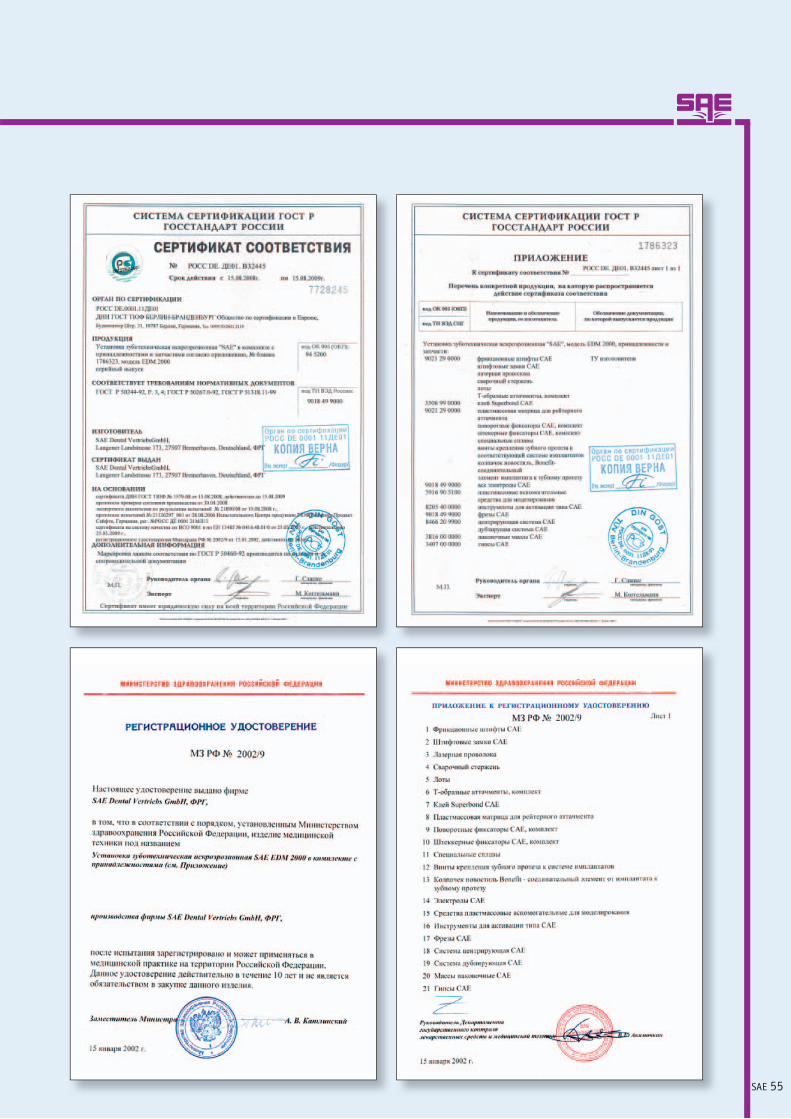
SAE 55

SAE DENTAL VERTRIEBS GMBH- INTERNATIONAL -
Postfach 10 07 60 · D-27507 Bremerhaven · Langener Landstraße 173 · D-27580 BremerhavenTel.: ++49 (0)471 9 84 87 45 · Fax: ++49 (0)471 9 84 87 44
E-Mail: [email protected] · Internet: www.sae-dental.de
Spannungsfreie Implantatstruktur mit SAE-Funkenerosionsiehe SAE-Secotec-Katalog
Stress-free Implant Framework by SAE Spark Erosion see SAE Secotec Catalogue
Per le strutture implantari avvitate senza tensione con l’elettroerosione SAE vedasi Catalogo SAE Secotec
Ненапряжённая структура на имплантатах путём искровой эрозии САЕсмотри САЕ-Секотек-Каталог