s. ulrich, j. ye, m. stüber, h. leiste robeko in-house
TRANSCRIPT
1
www.kit.edu
A new high performance micro wave plasma source
S. Ulrich, J. Ye, M. Stüber, H. Leiste
Institute for Applied Materials (IAM-AWP), Department of Composites and Thin Films
robeko in-house exibition & workshop plasmatechnology, 30th September 2015
Outline
• Introduction & motivation
• High rate deposition of a-C:H with a microwave plasma source
• Deposition of coatings in the system Ti-C with HiPIMS
• Hybrid technology: HiPIMS/DC magnetron sputtering,
HiPIMS/ microwave plasma source deposition
• Summary and outlook
2
• Introduction & motivation
• High rate deposition of a-C:H with a microwave plasma source
• Deposition of coatings in the system Ti-C with HiPIMS
• Hybrid technology: HiPIMS/DC magnetron sputtering,
HiPIMS/ microwave plasma source deposition
• Summary and outlook
High performance plasma sources can be used for:
Introduction & motivation
- High-rate Ar ion etching
- The addition of nitrogen, carbon or oxygen ions and radicals
- Plasma nitriding or plasma oxidation
- High rate deposition of a-C:H and ta-C:H
- Developing PVD/PECVD hybrid processes
- High rate deposition of carbon-based low friction nanocomposites

3
Modified a-C:H coatings produced by a PECVD/PVD hybrid process
Introduction & motivation
0
5
10
15
20
25
30
35
-500-400-300-200-1000
HF-Substratvorspannung in V
Här
te in
GP
a
a-C:Ha-C:H(Si)a-C:H(Ti)a-C:H(B)
relaxation
r.f.-substrate bias in V
hard
ness
in G
Pa
- Independent particle fluxes forming a-C:H and adding Si, Ti or B
S. Ulrich, H. Holleck, H. Leiste, L. Niederberger,E. Nold, K. Sell, M. Stüber, J. Ye, C. Ziebert, P. Pesch, S. Sattel, Nano-scale, multi-functionalcoatings in the material system B-C-N-H, Surf. Coat. Technol. 200 1-4 (2005) 7-13
magnetronsputtersource
plasmasource
substrate
Introduction & motivation
HiPIMS
Pulsing allows us to use high peak power while keeping the average power relatively low, making it easy on power grid demands while reaching technologically interesting plasma states.
Advantages:
• film forming particles: ions• control of growth process• interface design is possible• high adhesion• compact morphology
Disadvantiges:
• redeposition process on target• low growth rate• arcing poisoning problems

4
• Introduction & motivation
• High rate deposition of a-C:H with a microwave plasma source
• Deposition of coatings in the system Ti-C with HiPIMS
• Hybrid technology: HiPIMS/DC magnetron sputtering,
HiPIMS/ microwave plasma source deposition
• Summary and outlook
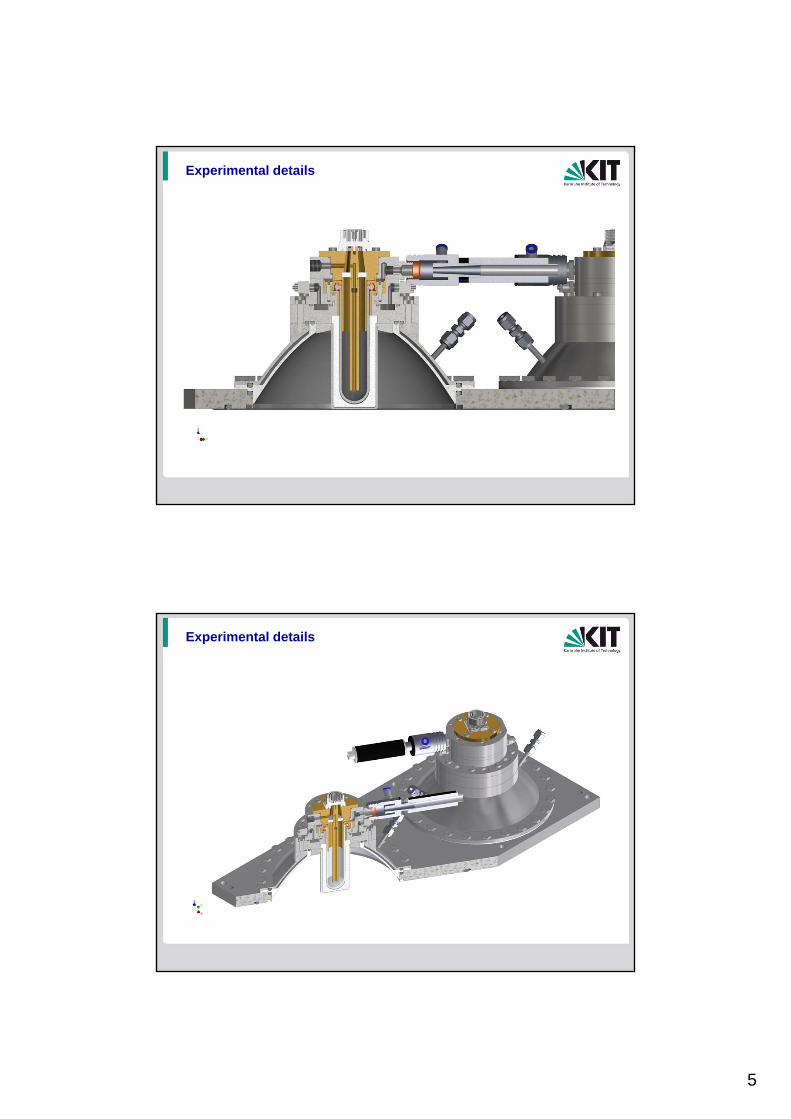
Experimental details
5
Experimental details
Experimental details

6
Experimental details
Experimental details
7
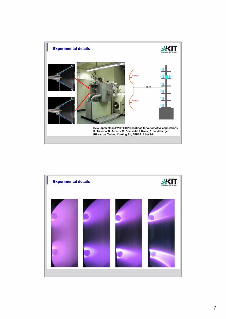
Experimental details
Developments in PVD/PECVD coatings for automotive applicationsR. Tietema, R. Jacobs, D. Doerwald, I. Kolev, J. LandsbergenIHI Hauzer Techno Coating BV, AEPSE, 22-WS-6
Experimental details

8
Selected results: variation of C2H2 flow rate
grow
th r
ate
in µ
m/h
C2H2 flow rate in sccm
330 sccm Arsingle plasma source: 1200 W
250 sccm Ar, full load2 plasma sources: 2 x 1200 W
Selected results: thickness profile using 1 source
30 min deposition duration

9
Selected results: homogenity
Selected results: homogenity
grow
th r
ate
in µ
m/h
P2 P4P3
substrate position
homogenity single source operation: R(P4) = 50% R(P2)homogenity 2 sources operation: R(P4) = 66% R(P2)
10
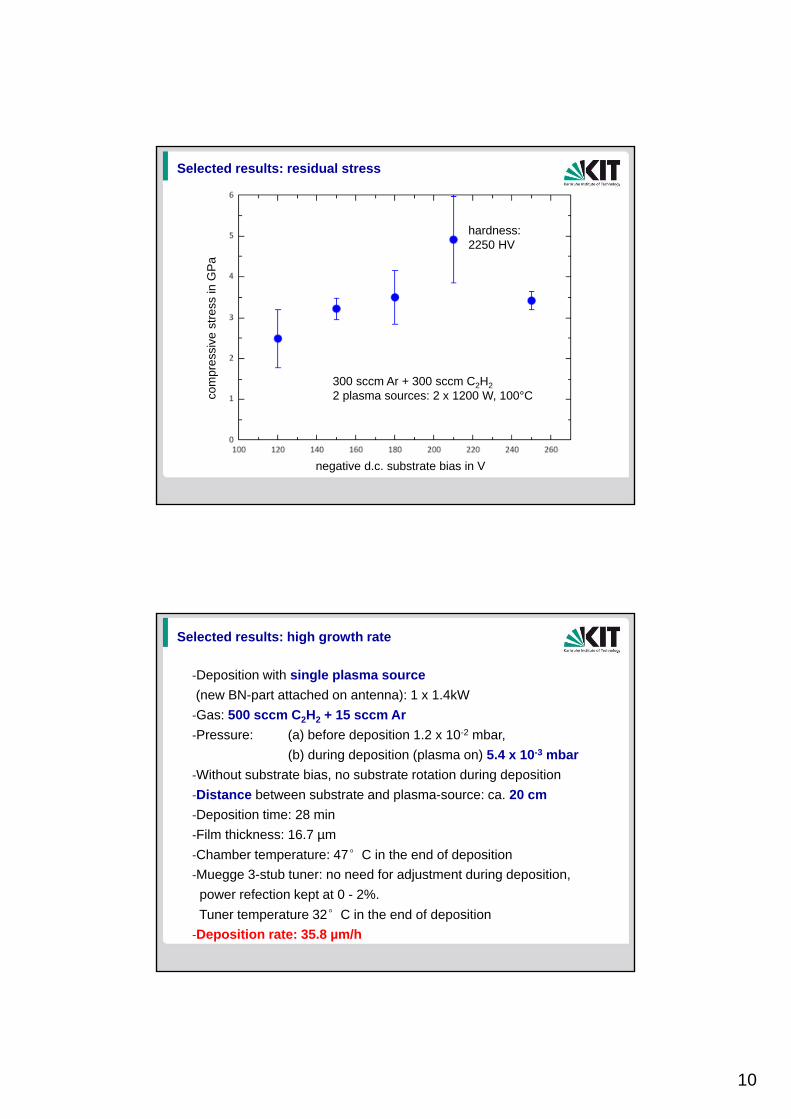
Selected results: residual stress
negative d.c. substrate bias in V
com
pres
sive
str
ess
in G
Pa
300 sccm Ar + 300 sccm C2H2
2 plasma sources: 2 x 1200 W, 100°C
hardness:2250 HV
Selected results: high growth rate
‐Deposition with single plasma source
(new BN-part attached on antenna): 1 x 1.4kW
‐Gas: 500 sccm C2H2 + 15 sccm Ar
‐Pressure: (a) before deposition 1.2 x 10⁻² mbar,
(b) during deposition (plasma on) 5.4 x 10⁻³ mbar
‐Without substrate bias, no substrate rotation during deposition
‐Distance between substrate and plasma-source: ca. 20 cm
‐Deposition time: 28 min
‐Film thickness: 16.7 µm
‐Chamber temperature: 47°C in the end of deposition
‐Muegge 3-stub tuner: no need for adjustment during deposition,
power refection kept at 0 - 2%.
Tuner temperature 32°C in the end of deposition
‐Deposition rate: 35.8 µm/h

11
Selected results: plasma diagnostics
400 600 800 1000 1200200
400
600
800
1000
1200
ion
sa
tura
tio
n c
urr
en
t d
en
sit
y (A
/cm
2)
power on each source (W)
source 1 + 21.0 Pa, 700 sccm Ar
Selected results: plasma diagnostics
400 600 800 1000 1200200
300
400
500
600
700
800
900
1000
ion
sa
tura
tio
n c
urr
en
t d
en
sit
y (A
/cm
2)
power on top source (W)
top source: onbottom source: off700 sccm Ar, 1.0 Pa
12
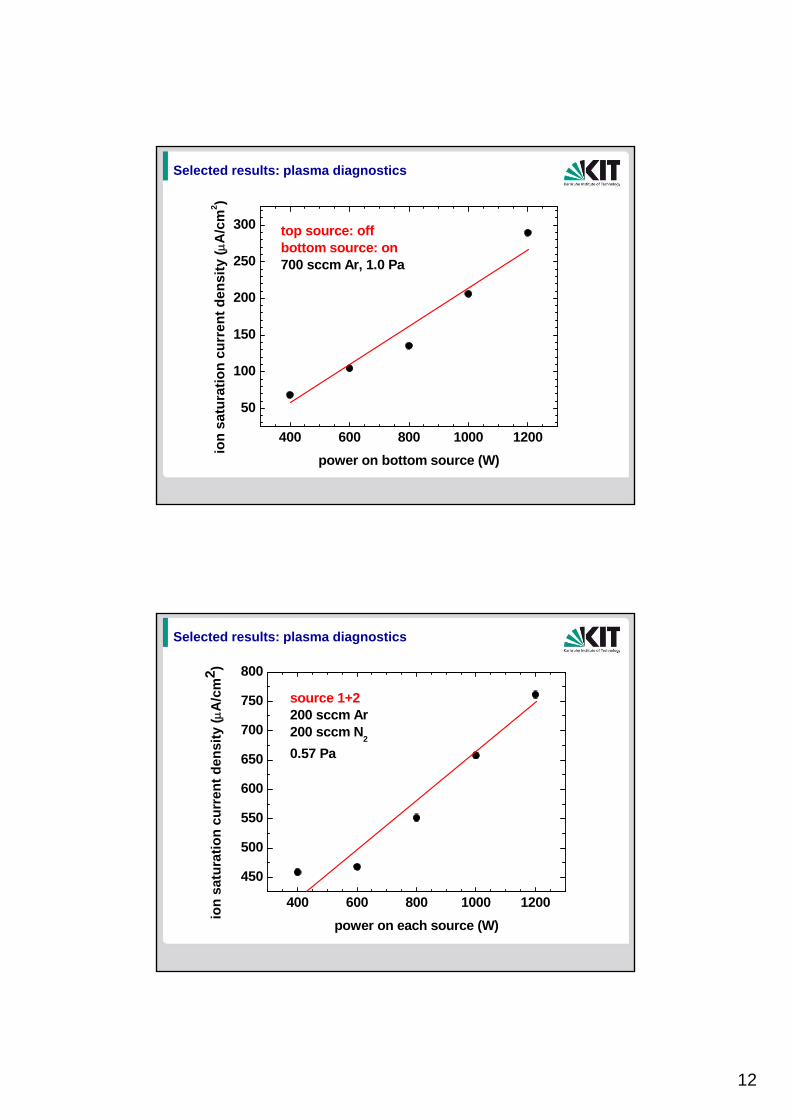
Selected results: plasma diagnostics
400 600 800 1000 1200
50
100
150
200
250
300
ion
sa
tura
tio
n c
urr
en
t d
en
sit
y (A
/cm
2)
power on bottom source (W)
top source: offbottom source: on700 sccm Ar, 1.0 Pa
Selected results: plasma diagnostics
400 600 800 1000 1200
450
500
550
600
650
700
750
800
ion
sat
ura
tio
n c
urr
ent
den
sity
(A
/cm
2 )
power on each source (W)
source 1+2200 sccm Ar 200 sccm N
2
0.57 Pa

13
Selected results: plasma diagnostics
100 200 300 400 500 6001
2
3
4
5
6
7
source 1+22 x 1000W200 sccm N
2pla
sma
po
ten
tial
(eV
)
argon flow rate (sccm)
Application: low ion energy incombination with high ion current densities
A. Anders, Thin Solid Film (2009)
14
• Introduction & motivation
• High rate deposition of a-C:H with a microwave plasma source
• Deposition of coatings in the system Ti-C with HiPIMS
• Hybrid technology: HiPIMS/DC magnetron sputtering,
HiPIMS/ microwave plasma source deposition
• Summary and outlook
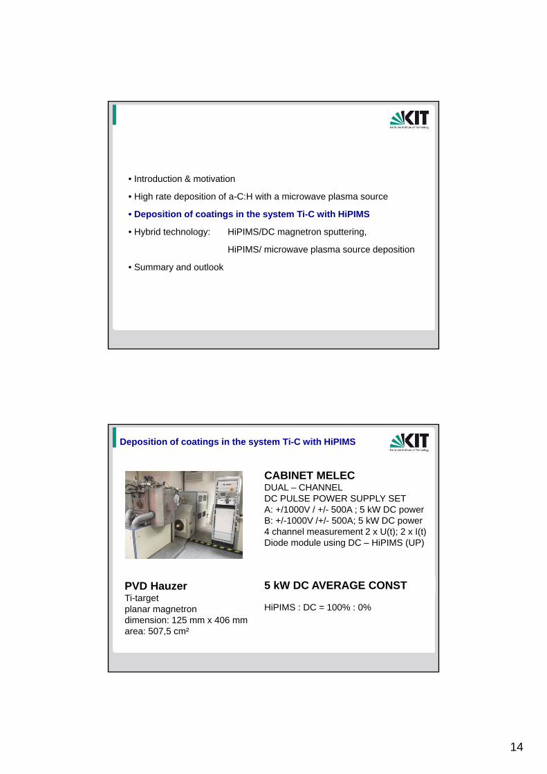
Deposition of coatings in the system Ti-C with HiPIMS
PVD HauzerTi-targetplanar magnetron dimension: 125 mm x 406 mmarea: 507,5 cm²
CABINET MELEC DUAL – CHANNELDC PULSE POWER SUPPLY SETA: +/1000V / +/- 500A ; 5 kW DC powerB: +/-1000V /+/- 500A; 5 kW DC power4 channel measurement 2 x U(t); 2 x I(t)Diode module using DC – HiPIMS (UP)
5 kW DC AVERAGE CONST
HiPIMS : DC = 100% : 0%

15
0 5 10 15 20 25 30 35 400
500
1000
1500
2000
2500
3000
3500V
icke
rs h
ardn
ess
[HV
0.0
5]
methan gas flow [sccm]
Deposition of coatings in the system Ti-C with HiPIMS
Ti Ti/TiC1-x TiC1-x TiC TiC/a-C:H
• Introduction & motivation
• High rate deposition of a-C:H with a microwave plasma source
• Deposition of coatings in the system Ti-C with HiPIMS
• Hybrid technology: HiPIMS/DC magnetron sputtering,
HiPIMS/ microwave plasma source deposition
• Summary and outlook

16
Hybrid technology: HiPIMS/DC magnetron sputtering
PVD HauzerTi-targetplanar magnetron dimension: 125 mm x 406 mmarea: 507,5 cm²
CABINET MELEC DUAL – CHANNELDC PULSE POWER SUPPLY SETA: +/1000V / +/- 500A ; 5 kW DC powerB: +/-1000V /+/- 500A; 5 kW DC power4 channel measurement 2 x U(t); 2 x I(t)Diode module using DC – HiPIMS (UP)
5 kW DC AVERAGE CONST
HiPIMS : DC = 100% : 0%
HiPIMS : DC = 70% : 30% HiPIMS : DC = 30% : 70%
Hybrid technology: HiPIMS/DC magnetron sputtering
M. Mark, G. Mark: Pluse textbook
17
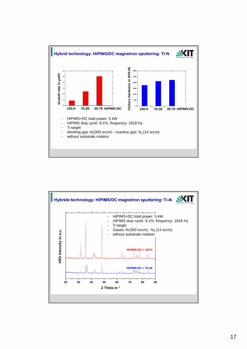
Hybrid technology: HiPIMS/DC magnetron sputtering: Ti-N
100:0 70:30 30:700
1
2
3
4
5
6
Gro
wth
Rat
e in
µm
/h
HiPIMS:DC 100:0 70:30 30:700
500
1000
1500
2000
2500
3000
Vic
kers
Har
dn
ess
in H
V0.
05
HiPIMS:DC
- HiPIMS+DC total power: 5 kW- HiPIMS duty cycle: 9.1%, frequency: 1818 Hz- Ti target- Working gas: Ar(300 sccm) – reactive gas: N2 (14 sccm)- without substrate rotation
Gro
wth
rat
e in
µm
/h
Vic
kers
har
dn
ess
in H
V0.
05
100:0 70:30 30:70 100:0 70:30 30:70HiPIMS:DC HiPIMS:DC
20 30 40 50 60 70 80 90
HiPIMS:DC = 70:30
XR
D In
ten
sity
in a
.u.
2 Theta in °
HiPIMS:DC = 100:0
- HiPIMS+DC total power: 5 kW- HiPIMS duty cycle: 9.1%, frequency: 1818 Hz- Ti target- Gases: Ar(300 sccm) - N2 (14 sccm)- without substrate rotation

18
Hybrid technology: HiPIMS/DC magnetron sputtering: Ti-C-N
100:0 70:30 30:700
1
2
3
4
5
Gro
wth
Rat
e in
µm
/h
HiPIMS:DC 100:0 70:30 30:700
500
1000
1500
2000
2500
3000
Vic
kers
Ha
rdn
ess
in H
V0
.05
HiPIMS:DC
- HiPIMS+DC total power: 5 kW- HiPIMS duty cycle: 9.1%, frequency: 1818 Hz- Ti target- working gas: Ar (300 sccm) – reactive gases: N2 (8 sccm) - CH4 (methan: 4 sccm)- without substrate rotation
Gro
wth
rat
e in
µm
/h
100:0 70:30 30:70 100:0 70:30 30:70HiPIMS:DC HiPIMS:DC
Vic
kers
har
dn
ess
in H
V0.
05
Hybrid technolgy: HiPIMS/DC magnetron sputtering: TI-C-N
20 30 40 50 60 70 80 90
HiPIMS:DC = 30:70
HiPIMS:DC = 70:30
HiPIMS:DC = 100:0
XR
D In
ten
sity
in a
.u.
2 Theta in °
- HiPIMS+DC total power: 5 kW- HiPIMS duty cycle: 9.1%, frequency: 1818 Hz- Ti target- working gas: Ar(300 sccm)-N2 (8 sccm)-CH4 (4 sccm)- without substrate rotation
19
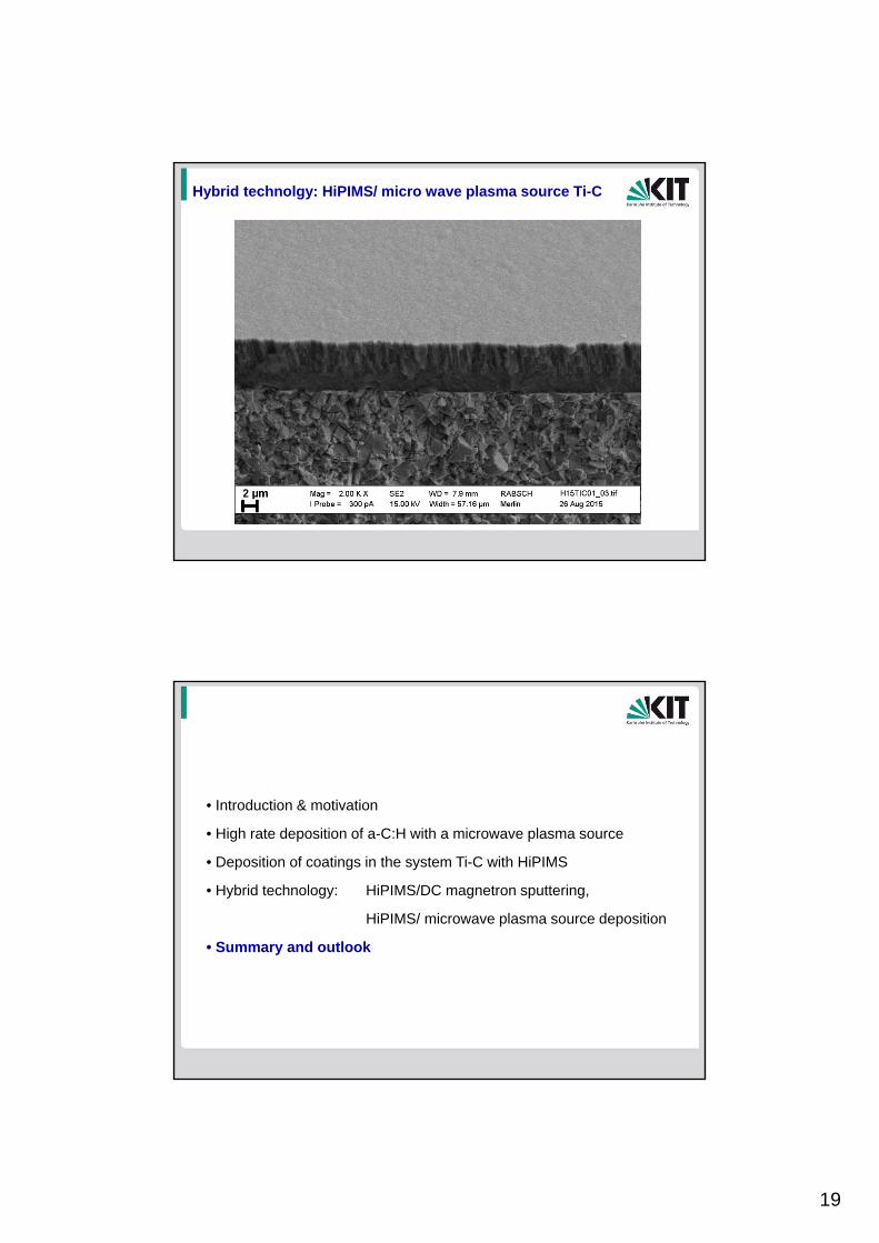
Hybrid technolgy: HiPIMS/ micro wave plasma source Ti-C
• Introduction & motivation
• High rate deposition of a-C:H with a microwave plasma source
• Deposition of coatings in the system Ti-C with HiPIMS
• Hybrid technology: HiPIMS/DC magnetron sputtering,
HiPIMS/ microwave plasma source deposition
• Summary and outlook

20
Summary – a-C:H (MW plasma)
• successful integration of 2 plasma sources in Hauzer coating facility
• commerial available Hauzer facility: 1200 W, 100% C2H2, 700 sccm C2H2, 36 µm/h, 6 µm/h with 2-fold rotation
• - stable operation (in time, variation of load, ...)
• hardness (300 sccm Ar, 40 sccm C2H2, -80 V substrate bias) = 2600 HV
• operation with 100% C2H2 possible
• low plasma potential between 2 eV and 10 eV
• ion current densities of 1 mA/cm2 at large distances
Summary – Ti-N, Ti-C-N (Hybrid technology: HiPIMS/DC)
• Inreasing of growth rate HiPIMS/DC using mixed mode by a factorof 5 for Ti-N and 4 for Ti-C-N compared to HiPIMS only
• Hardness and microstructure is nearly not effected
• New way of process optimization HiPIMS/DC grandied coatingse. g. interface design, design of nucleation and growth phase
• HiPIMS/DC is an evolving technology with high potential concerningdepositions rate, film properties and structural design
• HiPIMS can be performed in bipolar mode, improved process stability,arc prevention (pulse package mode), control of residual stress ,mechanical properties
Summary – Ti-C (Hybrid technology: HiPIMS/MW plasma)
• successful deposition of coatings in the system Ti-C by HiPIMS and HiPIMS/microwave plasma source
• Stable process conditions
21
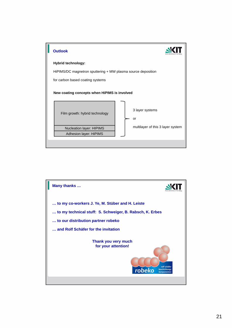
Outlook
Hybrid technology:
HiPIMS/DC magnetron sputtering + MW plasma source deposition
for carbon based coating systems
New coating concepts when HiPIMS is involved
Film growth: hybrid technology
Nucleation layer: HIPIMS
Adhesion layer: HiPIMS
3 layer systems
or
multilayer of this 3 layer system
Thank you very much for your attention!
Many thanks …
… to my co-workers J. Ye, M. Stüber and H. Leiste
… to our distribution partner robeko
… and Rolf Schäfer for the invitation
… to my technical stuff: S. Schweiger, B. Rabsch, K. Erbes
22
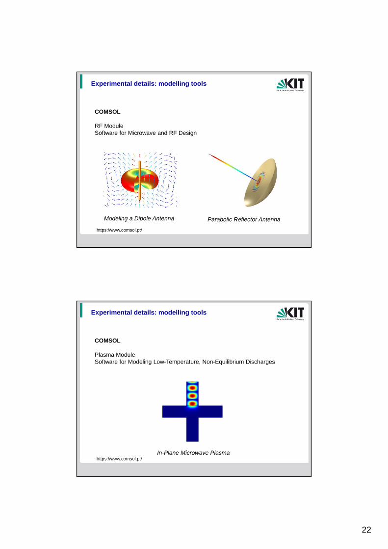
Experimental details: modelling tools
COMSOL
RF ModuleSoftware for Microwave and RF Design
Modeling a Dipole Antenna Parabolic Reflector Antenna
https://www.comsol.pt/
Experimental details: modelling tools
COMSOL
Plasma ModuleSoftware for Modeling Low-Temperature, Non-Equilibrium Discharges
In-Plane Microwave Plasmahttps://www.comsol.pt/
23
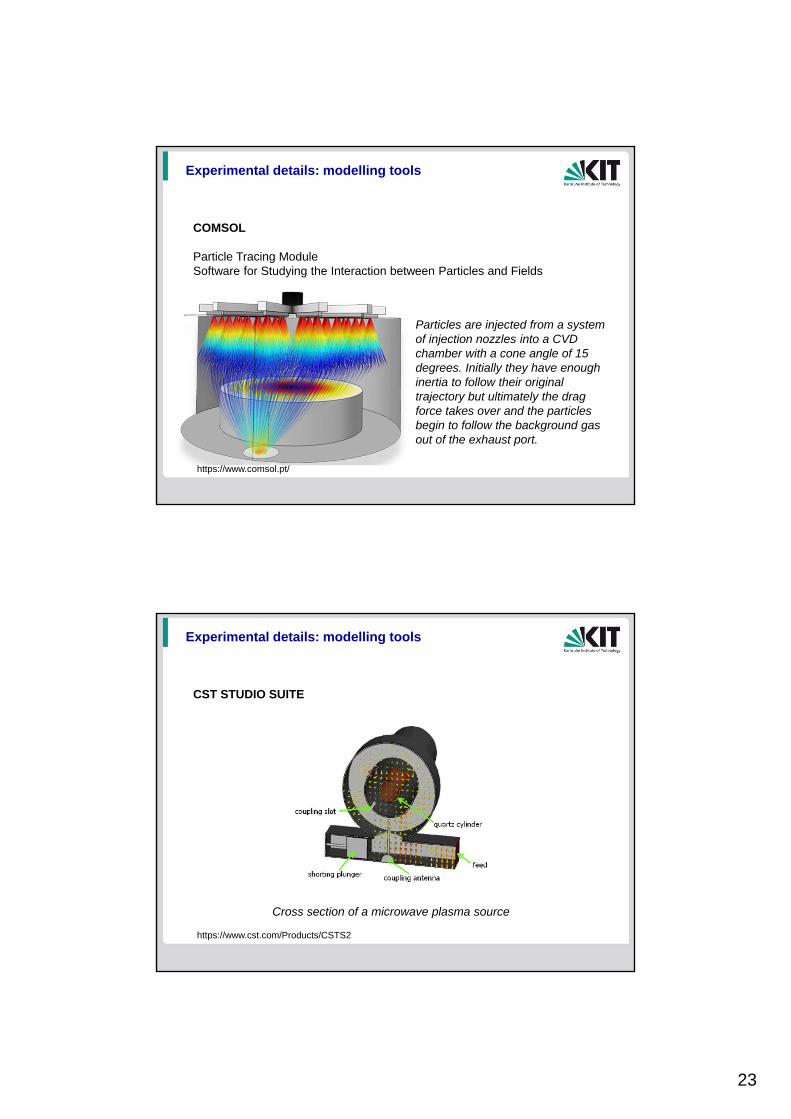
Experimental details: modelling tools
COMSOL
Particle Tracing ModuleSoftware for Studying the Interaction between Particles and Fields
Particles are injected from a system of injection nozzles into a CVD chamber with a cone angle of 15 degrees. Initially they have enough inertia to follow their original trajectory but ultimately the drag force takes over and the particles begin to follow the background gas out of the exhaust port.
https://www.comsol.pt/
Experimental details: modelling tools
CST STUDIO SUITE
https://www.cst.com/Products/CSTS2
Cross section of a microwave plasma source