s itch on - hpl india
TRANSCRIPT

HPL Electric & Power Ltd
HPL Electric & Power Ltd
TAB0 : Frame Rating 10A to 125A
TAB1 : Frame Rating 20A to 160A
TAB2 : Frame Rating 63A to 250A
TAB3 : Frame Rating 250A to 500A
TAB4 : Frame Rating 500A to 800A
TAB : Thermal Adjustable Breaker
your electrical protectionS itch on
TA
B M
CC
B C
AT.
/ 0
3-1
9
Corp. Office: Windsor Business Park, B-1D, Sector-10, Noida, U.P. - 201301, INDIA. Tel.: +91-120-4656300, Fax: +91-120-4656333Registered Office: 1/20, Asaf Ali Road, New Delhi - 110 002, INDIA.E-mail: [email protected]; [email protected]
HPL Electric & Power Ltd Customer Care No. :18004190198
Agartala
Agra
Allahabad
Anantpuram
Aurangabad
Amravati
Akola
Angul
Bareilly
Balasore
Belgaum
Berhampur
Bhilai
Bhopal
Bilaspur
Bijapur
Calicut
Cuttack
Davangere
Durg
Goa
Gorakhpur
Gulbarga
Jabalpur
Jabli
Jamshedpur
Jalandhar
Jharsuguda
Jodhpur
Kanyakumari
Kolhapur
Kota
Madurai
Malda
Mangalore
Meerut
Moradabad
Mysore
Nagerkoil
Nasik
Patiala
Pondicherry
Rajkot
Rourkela
Salem
Silchar
Surat
Sholapur
Srinagar
Sambalpur
Tirupati
Trichy
Trivandrum
Udaipur
Vapi
Varanasi
Vellore
MUMBAI
2C/H, Rushabh Chambers, 2nd Floor,
Off-Makwana Road, Near Rubi Hotel, Marol,
Andheri East, Mumbai-400059
E-mail: [email protected]
NAGPUR
Jagtap House, Plot No. 07,
Ist Floor, Ganesh Gruh Nirman Society,
Near Ganesh Mandir, Ring Road,
Pratap Nagar, Nagpur-440022,
Ph.: 0712-2222988
E-mail: [email protected]
PUNE
Sunrise Skyline 3rd Floor,
Plot No. 28/2 Scheme No. 11 B
Opp. MSEB Office Somwar Peth
Pune-411001 Ph.: +91 9028032724
E-mail: [email protected]
PATNA
Hem Plaza, 5th Floor - 510
Frazer Road, Patna-800001(Bihar)
Ph. : +91 9334697299
E-mail: [email protected]
RAIPUR
1st Floor, Near Holy Heart School
Chattisgarh College Road, Civil Line,
Raipur (C.G.)-492006 Ph.: 0771-4218002/04
E-mail: [email protected]
RANCHI
203, 2nd Floor, Mahalaxmi Complex,
Line Tank Road, Ranchi-834001
Telefax: 0651-2206144
E-mail: [email protected]
VADODARA
409/410, Silver Oak Complex,
Near Sainik Park, Char Rasta,
Productivity Road, Akota,
Vadodara - 390020 Gujarat
Ph.: 0265-2341747, Fax:0265-2352107
E-mail: [email protected]
VIJAYAWADA
D.No.-29-37-135, 2nd Floor,
G. R. Plaza, Eluru Road,
Beside Canara Bank, Vijayawada-520002
Ph.: 0866-6622291
E-mail: [email protected]
VIZAG
B.K. Towers, 49-34-1/63, 3rd Floor
Akka Yyapalem Main Road, NH-5 Junction,
Vizag-530016 (A.P.)
Ph.: 0891-2794506
E-mail: [email protected]
AHMEDABAD
B-802, Iscon Elegance, Nr. Prahlad
Nagar Corner, Opp. Karnavati Club,
S.G. Highway, Ahmedabad-380051
Ph.: 079 - 66168835/36
E-mail: [email protected]
BANGALORE
No.2D, IInd Floor, Farah Winsford,
133, Infantry Road, Bangalore - 560001
Ph.: 080-22863068/69
E-mail: [email protected]
CHENNAI
"Amar Sindur" S-4, 2nd Floor,
No.-43, Pantheon Road, Egmore,
Chennai-600 008
Ph.: 044-28551530, 28551537
Fax: 044-42638243
E-mail: [email protected]
COCHIN
1st Floor, A.K.S. Mahal Building,
XL/7813J, Achutha Warrier Lane,
M.G.Road, Ernakulam, Cochin-682035
Telefax: 0484-2354595
E-mail: [email protected]
BHUBANESWAR
N3-135, IRC Village, Nayabali,
Behind Old Sai Baba Temple,
Bhubaneswar-751012, Ph.: 0674-2550826
E-mail: [email protected]
DEHRADUN
09/4/6, Ist Floor, East Canal Road,
(Near Doon Defence Academy)
Dehradun-248001
Ph.: 0135-2710567, 2710587
E-mail: [email protected]
COIMBATORE
Designer Complex, Door No.130,
C/2, 2nd Floor, Dr. Nanjappa Road,
Coimbatore - 641018
Ph.: 0422-4393995
E-mail: [email protected]
GUWAHATI
Rajgarh Road, Opposite China Town
Restaurant, Guwahati-781003
Ph.: 0361-2450889
E-mail: [email protected]
INDORE
203, Millinda Manor 2, RNT Marg,
Near Ravindra Natya Grah, Indore-452001,
Ph.: 0731-4280525, 4225540
E-mail: [email protected]
KOLKATA
69, Ganesh Chandra Avenue, India House,
7th Floor, Block-C, Kolkata-700013
Ph.: +91 9038094379
E-Mail: [email protected]
LUCKNOW
1st Floor, Jain Building, 14/A5,
Park Road Hazratganj ,Lucknow-226001
Ph.: 0522-4021687
E-Mail: [email protected]
HUBLI
9-10, 1st Floor, Vernekar Plaza,
Desh Pande Nagar, Hubli-580029
Ph.: 0836-4251463
E-mail: [email protected]
HYDERABAD
No. 7-1-58, Flat No.403, 4th Floor,
Concourse Building, Green
Lands Road, Hyderabad-500016
Ph.: 040-66687878
E-mail: [email protected]
JAIPUR
512, 5th Floor, Plot No. 8-9,
Corporate Park, Gopal Bari,
Ajmer Road, Jaipur-302001
Ph.: 0141-4021035
E-Mail: [email protected]
JAMMU
Plot No.86, Yard No.6,
Transport Nagar, Jammu-180006
E-mail: [email protected]
SILIGURI
1st Floor, Parasuna Bhawan, Ward No.13,
Udham Singh Sarani, Asram Para,
Siliguri-734001
CHANDIGARH
SCO-14, 1st Floor, Industrial & Business
Park, Phase-II, Chandigarh-160002
Ph.: 0172-2639157/ 8146404442
E-mail: [email protected]
LUDHIANA
698 - D, Model Town Extn.,
Opp. Silverstone Hotel, Ludhiana-141003
Ph.: 0161-4062877
E-Mail: [email protected]
HPL Electric & Power Ltd
2 3
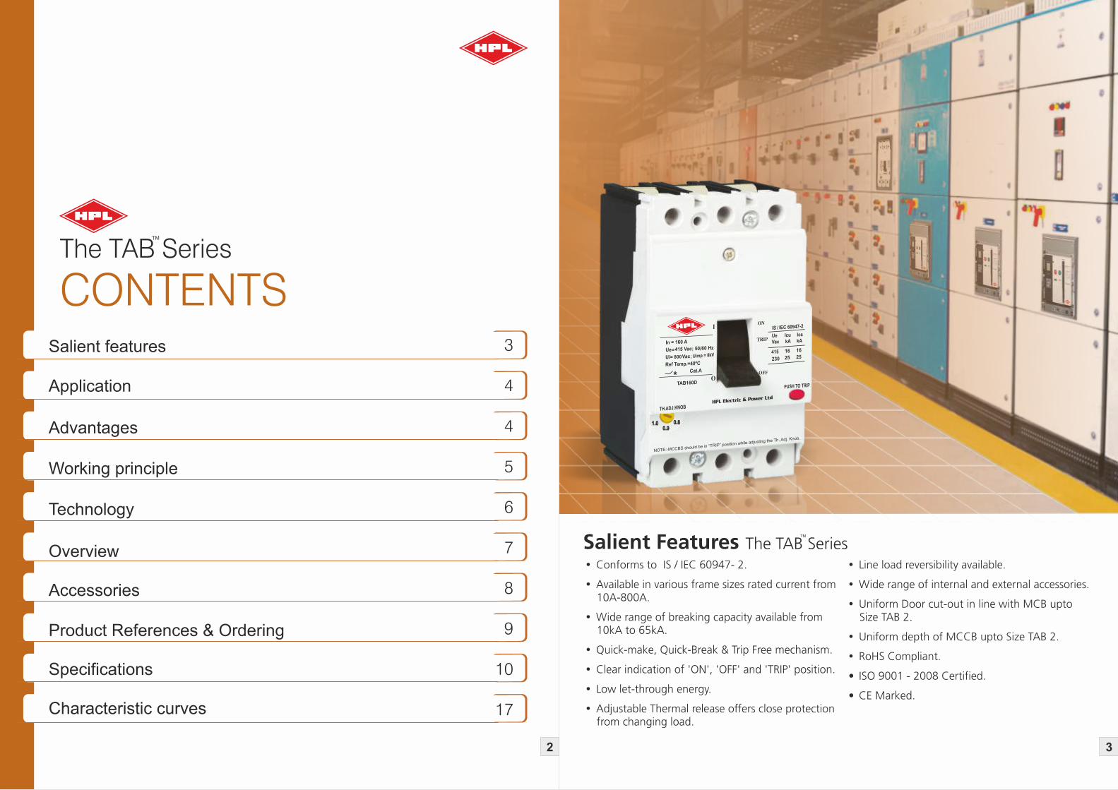
CONTENTSSalient features
Advantages
Technology
Working principle
Accessories
Characteristic curves
3
4
4
5
6
7
8
9
10
17
Application
Overview
Specifications
Product References & Ordering
The TAB Series
Salient FeaturesŸ Conforms to IS / IEC 60947- 2.
Ÿ Available in various frame sizes rated current from 10A-800A.
Ÿ Wide range of breaking capacity available from 10kA to 65kA.
Ÿ Quick-make, Quick-Break & Trip Free mechanism.
Ÿ Clear indication of 'ON', 'OFF' and 'TRIP' position.
Ÿ Low let-through energy.
Ÿ Adjustable Thermal release offers close protection from changing load.
Ÿ Line load reversibility available.
Ÿ Wide range of internal and external accessories.
Ÿ Uniform Door cut-out in line with MCB upto Size TAB 2.
Ÿ Uniform depth of MCCB upto Size TAB 2.
Ÿ RoHS Compliant.
• ISO 9001 - 2008 Certified.
• CE Marked.
The TAB Series

Applications
Distribution feeder protection
Transformer protection
DG set protection
Motor protection
Capacitor protection
Protection for semi-conductor
fuses
UPS protection
DC load protection
Suited for incoming and
outgoing feeders
Effective protection to
distribution transformers as
outgoing breakers.
Used for protection and control
of diesel generating sets against
overloads and short circuits.
MCCB provides motor back up
protection, provide type -2 co-
ordination (as per IEC 60947) in
conjunction with suitably rated
contactors and relays.
Used to protect capacitors.
Used to protect semiconductor
fuses.
Used for UPS and electronic
equipment protection.
Suitable for both AC as well as
DC application for protecting
rectifier panel.
MCCB is suitable for circuit protection in individual enclosures, switch board, lighting and power panels as well as motor control centers.
MCCB is assigned to protect systems against overload and short circuit up to 65KA with full range of accessories.
TMTAB ........series provides the following applications :-
Ics = O-CO-CO
The rise in temperature on the terminals, body etc. after the S.C. breaking capacity test is well within limits to give better life to the product and also safeguards the entire distribution system.
Insulation
Operating Knob/Dolly is made of Thermoplastic insulating material to make it safer & reliable.
Utilization Category
Utilization category for a circuit breaker shall be stated with reference to whether or not it is specifically intended for selectivity by means of an intentional time delay (with respect to other circuit breaker in series). Utilization category is a regulation on application with respect to selectivity.
1. Utilization Category “A” :
Circuit breaker not specifically intended for selectivity under short circuit conditions. Such breakers do not have a short time withstand current rating. All Thermal-Magnetic breakers satisfy utilization category “A”.
2. Utilization Category “B" :
Circuit breaker specifically intended for selectivity under short circuit conditions. Such breakers have a short time withstand current rating. All electronic–type breakers satisfy utilization category “B”.
Working PrincipleTMTAB .....Series breakers work on current limiting principle.
Current limiting capacity of a circuit breaker is its aptitude to limit short-circuit current. When a short circuit occurs, the breaker is able
2to limit and lower the I t energy release in very short time so as to protect circuits and switchgear at downstream. This is achieved by
Ÿ Intelligent design of Arc Chamber
Ÿ Guiding the arc rapidly away from the contacts in the arc chamber.
Ÿ Quick opening of main contacts.
Ÿ Quick quenching of arc by using effective arc quenching methods & materials.
Therefore Ipk is limited to Ic which leads to substantial reduction in 2electrodynamic stresses in the system. Also I t let through
proportional to the shaded area is considerably reduced, resulting in lower thermal stresses in downstream equipment and connecting cables.
Ipk
Ic
Advantages1. Compactness :
It is very compact in size and hence helps in saving space in the enclosures, panels etc. Due to its slim size it uses the distribution space very efficiently regardless of fact whether it is in residential or functional buildings.
2. Simplicity :
Its handling is easy and simple. Its simplicity and ease in use allows the user for quick installation.
3. Safe to use :
It is very safe to use. It protects people, installation and power supply distribution system. The insulation property of the material used is highly reliable and remains intact in even critical conditions.
Evolution
To reflect a variety of uses and applications, the line up has been expanded up to 65 KA with high specifications. As consumption of power is increasing, circuit breaker demands for a new level of functionality, flexibility, power and space saving has become imminent.
TMTAB …series of MCCBs are wtih improved performance and safety.
It conforms to the latest IS & IEC standards.
The IS/IEC 60947-2 specifies the Icu (rated ultimate short circuit) and Ics (rated service short circuit) breaking capacities to the following types:-
Icu = O-CO
4Thermal Adjustable Breaker 5Thermal Adjustable Breaker
Prospectivecurrent
Cut-off current
The TAB Series
HPL Electric & Power Ltd
HPL Electric & Power Ltd
Operating Conditions
1. Temperature : MCCBs are calibrated at 40°C as reference ambient Temperature. However with increase in ambient, compensation factor to be taken into consideration.
2. Altitude : It should be less than 2000m.
3. Pollution Degree : 3
Isolation Function
These MCCBs are suitable for isolation also. As defined in IS / IEC 60947 - 2, the operation of isolation function highlights the following points:-
Contacts operation correctly indicates operating reliability of interior mechanism.
No residual current.
Higher impulse withstand voltage for terminals at the power supply side and load side.
Line-load Reversibility
MCCBs have no bias of line & load connection. The power supply can be connected from either top or bottom which has no effect on normal operation of the breaker.
The Technology For MCCB Devices
1. Arc Chamber
The MCCB arc chamber is specially designed with an arc channel as a flow guide to improve the capability of extinguishing the arc and reducing the arc distance.
2. MCCB Base And Cover
Cover and Base moulding are made of superior quality of Thermoset & Thermoplastics to with stand the stringent short circuit conditions with very high insulation strength to avoid any damage to the product. Covers are secured on Base mouldings with mounting screws tightened into threaded inserts in the MCCB base to have better strength.
3. Fixed Contact
The MCCB fixed contact does not have any mounting screws near the contact points. A steel screw can generate heat and the magnetic flux surrounding the conductor carrying the current can create a very high temperature. If a short-circuit occurs, it will cause the contact points to be welded or melted.
4. Thermal Magnetic Tripping
1. In case of Thermal overload, time-delay operation occurs when an over current heats and warps the bimetal to actuate the trip bar. (See-'A')
2. In case of Magnetic tripping, when high current passes through, the magnetization of the fix core enables it to attract the armature fixed on trip bar thereby tripping the breaker. (See-'B')
1
2
3
4
B
A
Technology for MCCB Devices Overview
6Thermal Adjustable Breaker 7 Thermal Adjustable Breaker
The TAB SeriesThe TAB Series

It has a wide range of accessories giving convenience and additional protection. They are of two types.
1. Internal accessory
2. External accessory.
Internal Accessories:Shunt Trip Coil
It is a release energized by a source of voltage which may be independent of the voltage of the main circuit. It provides remote tripping of the circuit breaker. Once the MCCB trips it prevents burning of coil even if supply is continuous to coil. Its operating voltage is 70% to 110 % of rated voltage.
Undervoltage Release
It permits a mechanical switching device to open or close, with or without time delay, when voltage across release falls below a predetermind value. The normal working range is 35- 70% of the rated voltage.
Auxillary Switch
It is used for remote signaling and control purposes. It consists of one or more than one potential free change over contact and acts as an indicator whether the circuit breaker's status is open or closed.
Alarm Switch
It is an auxiliary switch which operates only upon the tripping of the circuit breaker. It gives tripping indication once the MCCB trips.
External Accessories:Rotary Handle
It is a toggle handle operating mechanism which serves as switching position indicator ON, OFF, TRIP. Basically it is used with breaker which is installed in an enclosure that does not allow ready access to the breaker's operating handle. The handle is allowed to be locked in the OFF or ON position for safety. This feature helps to reduce the risk associated with arc related flash burns.
Phase Barrier
Phase barriers are provided between the phases to increase the creepage distance between them thereby reducing the risk of phase to phase shorting.
Technical Features
1. Standard conformity :IS / IEC-60947-2
2. Rated operational voltage : 415V AC
3. Rated insulation voltage: 800V AC
4. Utilization category : A
5. Rated frequency: 50/60Hz.
6. Rated impulse voltage : 8kV
Accessories
8Thermal Adjustable Breaker
The TAB Series Product Reference & Ordering
Accessories for TAB MCCB
Frame Shunt Under Voltage Auxiliary Alarm Rotary
size Release Release Switch Switch Handle
TAB 0 110 VAC 110 VAC 1 C/O 1 C/O RHDM : Door Mounted
TAB 1 240 VAC 240 VAC 2 C/O RHCM : Breaker
TAB 2 415 VAC 415 VAC Mounted
TAB 3 024 VDC 024 VDC
TAB 4 048 VDC 048 VDC
Ÿ Product Reference for 230 VAC shunt release with TAB 1 is TAB160SHT230VAC
Ÿ Product Reference for 230 VAC under voltage release with TAB 1 is TAB160UVR230VAC
Ÿ Product Reference for 1 C/O Auxiliary switch with TAB 1 is TAB160AXC1
Ÿ Product Reference for 1 C/O Alarm Switch with TAB 1 is TAB160ALC1
Ÿ Product Reference for 1 C/O Alarm / Auxiliary Switch with TAB 1 is TAB160 ALAX
Ÿ Product Reference for Rotary Handle Door Mounted with TAB 1 RHCT1ACPDM
Ÿ A Maximum 2 Nos. Internal Accessories can be selected for one Breaker, one on each side
Ÿ Shunt or Under voltage release is fitted on LHS.
Ÿ Auxiliary / Alarm Switch is fitted on RHS.
9Thermal Adjustable Breaker
TAB 1
Ÿ TAB 0 MCCB is available with breaking capacity 10 kA
Ÿ TAB 1 MCCB is available with breaking capacity 10 kA / 16 kA / 25 kA / 36 kA
Ÿ TAB 2 MCCB is available with breaking capacity 25 kA / 36 kA / 50 kA
Ÿ TAB 3 MCCB is available with breaking capacity 36 kA / 50 kA / 65 kA
Ÿ TAB 4 MCCB is available with breaking capacity 50 kA / 65 kA
• DC Rating against request.
• Fixed Type MCCB available from 16A to 800A, 10kA to 65kA Breaking Capacity.
L X 100 AC 3P
The TAB Series
* SP MCCB in TAB 0 available from 16A to 160A, 10kA & 25kA breaking capacity
FrameSize
BreakingCapacity
Ics=% Icu
Rated Current *Tab 0
Rated CurrentTab 1
Rated CurrentTab 2
Rated CurrentTab 3
Rated CurrentTab 4
Current No. of Main Poles
TAB 0
TAB 1
TAB 2
TAB 3
TAB 4
L : 10kA
D : 16kA
K : 20kA
C : 25kA
N : 36kA
S : 50kA
H : 65kA
X = 100%
Y = 75%
Z = 50%
10
16
20
25
32
40
50
63
80
100
125
020
025
032
040
050
063
080
100
125
160
063
080
100
125
160
200
250
250
320
400
500
500
630
800
AC 2P
3P
4P
Specifications
10Thermal Adjustable Breaker
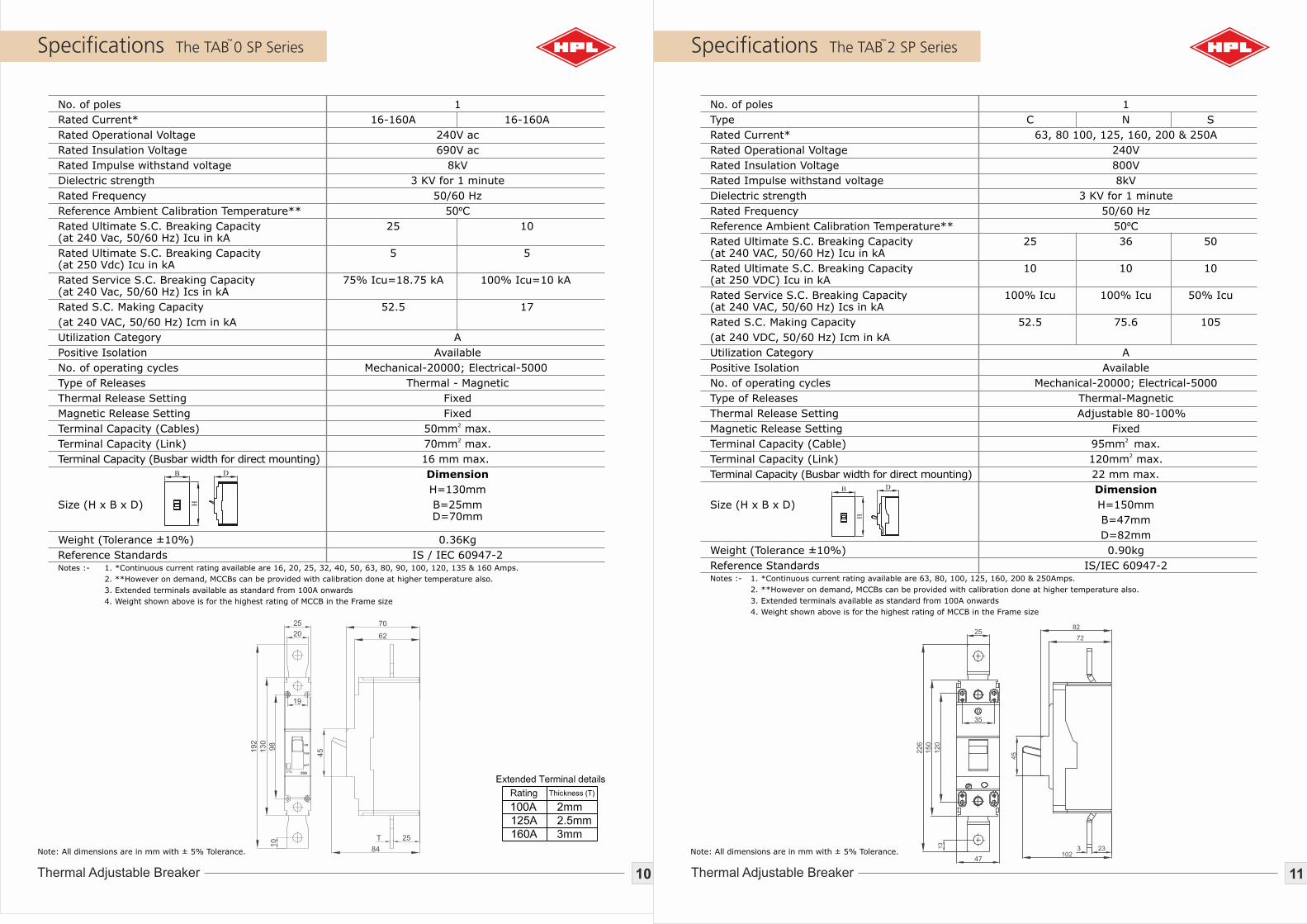
The TAB 0 SP Series Specifications
11Thermal Adjustable Breaker
The TAB 2 SP Series
No. of poles 1
Rated Current* 16-160A 16-160A
Rated Operational Voltage 240V ac
Rated Insulation Voltage 690V ac
Rated Impulse withstand voltage 8kV
Dielectric strength 3 KV for 1 minute
Rated Frequency 50/60 Hz
Reference Ambient Calibration Temperature** 50ºC
Rated Ultimate S.C. Breaking Capacity 25 10 (at 240 Vac, 50/60 Hz) Icu in kA
Rated Ultimate S.C. Breaking Capacity 5 5 (at 250 Vdc) Icu in kA
Rated Service S.C. Breaking Capacity 75% Icu=18.75 kA 100% Icu =10 kA(at 240 Vac, 50/60 Hz) Ics in kA
Rated S.C. Making Capacity 52.5 17
(at 240 VAC, 50/60 Hz) Icm in kA
Utilization Category A
Positive Isolation Available
No. of operating cycles Mechanical-20000; Electrical-5000
Type of Releases Thermal - Magnetic
Thermal Release Setting Fixed
Magnetic Release Setting Fixed2
Terminal Capacity (Cables) 50mm max.2
Terminal Capacity (Link) 70mm max.
Terminal Capacity (Busbar width for direct mounting) 16 mm max.
Dimension
H=130mm
Size (H x B x D) B=25mm D=70mm Weight (Tolerance ±10%) 0.36Kg
Reference Standards IS / IEC 60947-2Notes :- 1. *Continuous current rating available are 16, 20, 25, 32, 40, 50, 63, 80, 90, 100, 120, 135 & 160 Amps.
2. **However on demand, MCCBs can be provided with calibration done at higher temperature also.
3. Extended terminals available as standard from 100A onwards
4. Weight shown above is for the highest rating of MCCB in the Frame size
No. of poles 1
Type C N S
Rated Current* 63, 80 100, 125, 160, 200 & 250A
Rated Operational Voltage 240V
Rated Insulation Voltage 800V
Rated Impulse withstand voltage 8kV
Dielectric strength 3 KV for 1 minute
Rated Frequency 50/60 Hz
Reference Ambient Calibration Temperature** 50ºC
Rated Ultimate S.C. Breaking Capacity 25 36 50(at 240 VAC, 50/60 Hz) Icu in kA
Rated Ultimate S.C. Breaking Capacity 10 10 10(at 250 VDC) Icu in kA
Rated Service S.C. Breaking Capacity 100% Icu 100% Icu 50% Icu(at 240 VAC, 50/60 Hz) Ics in kA
Rated S.C. Making Capacity 52.5 75.6 105
(at 240 VDC, 50/60 Hz) Icm in kA
Utilization Category A
Positive Isolation Available
No. of operating cycles Mechanical-20000; Electrical-5000
Type of Releases Thermal-Magnetic
Thermal Release Setting Adjustable 80-100%
Magnetic Release Setting Fixed2
Terminal Capacity (Cable) 95mm max.2Terminal Capacity (Link) 120mm max.
Terminal Capacity (Busbar width for direct mounting) 22 mm max.
Dimension
Size (H x B x D) H=150mm
B=47mm
D=82mm
Weight (Tolerance ±10%) 0.90kg
Reference Standards IS/IEC 60947-2Notes :- 1. *Continuous current rating available are 63, 80, 100, 125, 160, 200 & 250Amps.
2. **However on demand, MCCBs can be provided with calibration done at higher temperature also.
3. Extended terminals available as standard from 100A onwards
4. Weight shown above is for the highest rating of MCCB in the Frame size
Note: All dimensions are in mm with ± 5% Tolerance. Note: All dimensions are in mm with ± 5% Tolerance.
22
6
15
0
12
0
25
35
47
13
82
72
233102
451
92
130
98
25
20
19
10
ON
TRIP
OFF
90APushto Trip
45
70
62
25
84
Specifications
13Thermal Adjustable Breaker
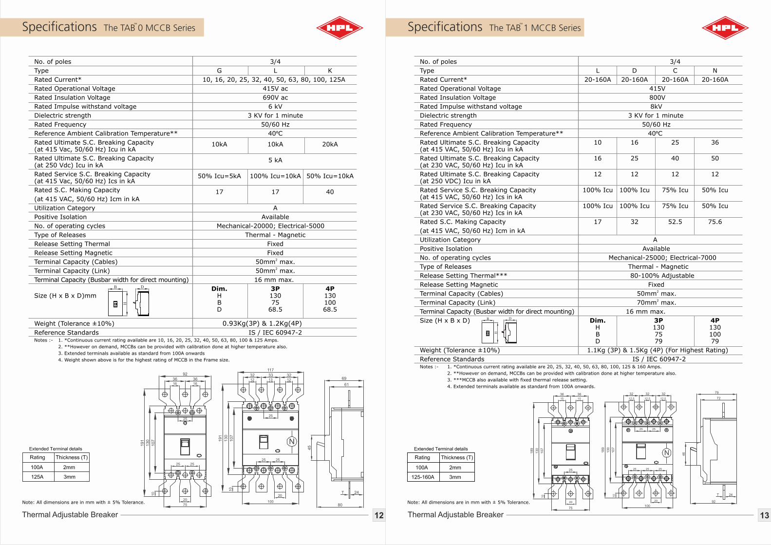
The TAB 1 MCCB Series
No. of poles 3/4
Type L D C N
Rated Current* 20-160A 20-160A 20-160A 20-160A
Rated Operational Voltage 415V
Rated Insulation Voltage 800V
Rated Impulse withstand voltage 8kV
Dielectric strength 3 KV for 1 minute
Rated Frequency 50/60 Hz
Reference Ambient Calibration Temperature** 40ºC
Rated Ultimate S.C. Breaking Capacity 10 16 25 36(at 415 VAC, 50/60 Hz) Icu in kA
Rated Ultimate S.C. Breaking Capacity 16 25 40 50(at 230 VAC, 50/60 Hz) Icu in kA
Rated Ultimate S.C. Breaking Capacity 12 12 12 12(at 250 VDC) Icu in kA
Rated Service S.C. Breaking Capacity 100% Icu 100% Icu 75% Icu 50% Icu(at 415 VAC, 50/60 Hz) Ics in kA
Rated Service S.C. Breaking Capacity 100% Icu 100% Icu 75% Icu 50% Icu(at 230 VAC, 50/60 Hz) Ics in kA
Rated S.C. Making Capacity 17 32 52.5 75.6
(at 415 VAC, 50/60 Hz) Icm in kA
Utilization Category A
Positive Isolation Available
No. of operating cycles Mechanical-25000; Electrical-7000
Type of Releases Thermal - Magnetic
Release Setting Thermal*** 80-100% Adjustable
Release Setting Magnetic Fixed2
Terminal Capacity (Cables) 50mm max.2
Terminal Capacity (Link) 70mm max.
Terminal Capacity (Busbar width for direct mounting) 16 mm max.
Size (H x B x D) Dim. 3P 4P H 130 130 B 75 100 D 79 79
Weight (Tolerance ±10%) 1.1Kg (3P) & 1.5Kg (4P) (For Highest Rating)
Reference Standards IS / IEC 60947-2Notes :- 1. *Continuous current rating available are 20, 25, 32, 40, 50, 63, 80, 100, 125 & 160 Amps.
2. **However on demand, MCCBs can be provided with calibration done at higher temperature also.
3. ***MCCB also available with fixed thermal release setting.
4. Extended terminals available as standard from 100A onwards.
Specifications
12Thermal Adjustable Breaker
The TAB 0 MCCB Series
No. of poles 3/4
Type G L K
Rated Current* 10, 16, 20, 25, 32, 40, 50, 63, 80, 100, 125A
Rated Operational Voltage 415V ac
Rated Insulation Voltage 690V ac
Rated Impulse withstand voltage 6 kV
Dielectric strength 3 KV for 1 minute
Rated Frequency 50/60 Hz
Reference Ambient Calibration Temperature** 40ºC
Rated Ultimate S.C. Breaking Capacity 10kA 10kA 20kA (at 415 Vac, 50/60 Hz) Icu in kA
Rated Ultimate S.C. Breaking Capacity 5 kA (at 250 Vdc) Icu in kA
Rated Service S.C. Breaking Capacity 50% Icu=5kA 100% Icu=10kA 50% Icu=10kA(at 415 Vac, 50/60 Hz) Ics in kA
Rated S.C. Making Capacity 17 17 40(at 415 VAC, 50/60 Hz) Icm in kA
Utilization Category A
Positive Isolation Available
No. of operating cycles Mechanical-20000; Electrical-5000
Type of Releases Thermal - Magnetic
Release Setting Thermal Fixed
Release Setting Magnetic Fixed2
Terminal Capacity (Cables) 50mm max.2Terminal Capacity (Link) 50mm max.
Terminal Capacity (Busbar width for direct mounting) 16 mm max.
Dim. 3P 4P Size (H x B x D)mm H 130 130 B 75 100 D 68.5 68.5 Weight (Tolerance ±10%) 0.93Kg(3P) & 1.2Kg(4P)
Reference Standards IS / IEC 60947-2Notes :- 1. *Continuous current rating available are 10, 16, 20, 25, 32, 40, 50, 63, 80, 100 & 125 Amps.
2. **However on demand, MCCBs can be provided with calibration done at higher temperature also.
3. Extended terminals available as standard from 100A onwards
4. Weight shown above is for the highest rating of MCCB in the Frame size.
18
9
13
0
10
7
32 32 32
12.5 12.5 12.5
25 25
25 25 25
20
100
10
18
9
13
0
10
7
36 36
15 15
25
20
75
10
79
72
24
92
46
Note: All dimensions are in mm with ± 5% Tolerance. Note: All dimensions are in mm with ± 5% Tolerance.
191
130
107
36 3616 16
25
25 25
20
75
10
92
191
130
107
117
32 33 3212 13 12
25
25 25
20
100
10
69
61
24
80
45
15Thermal Adjustable Breaker
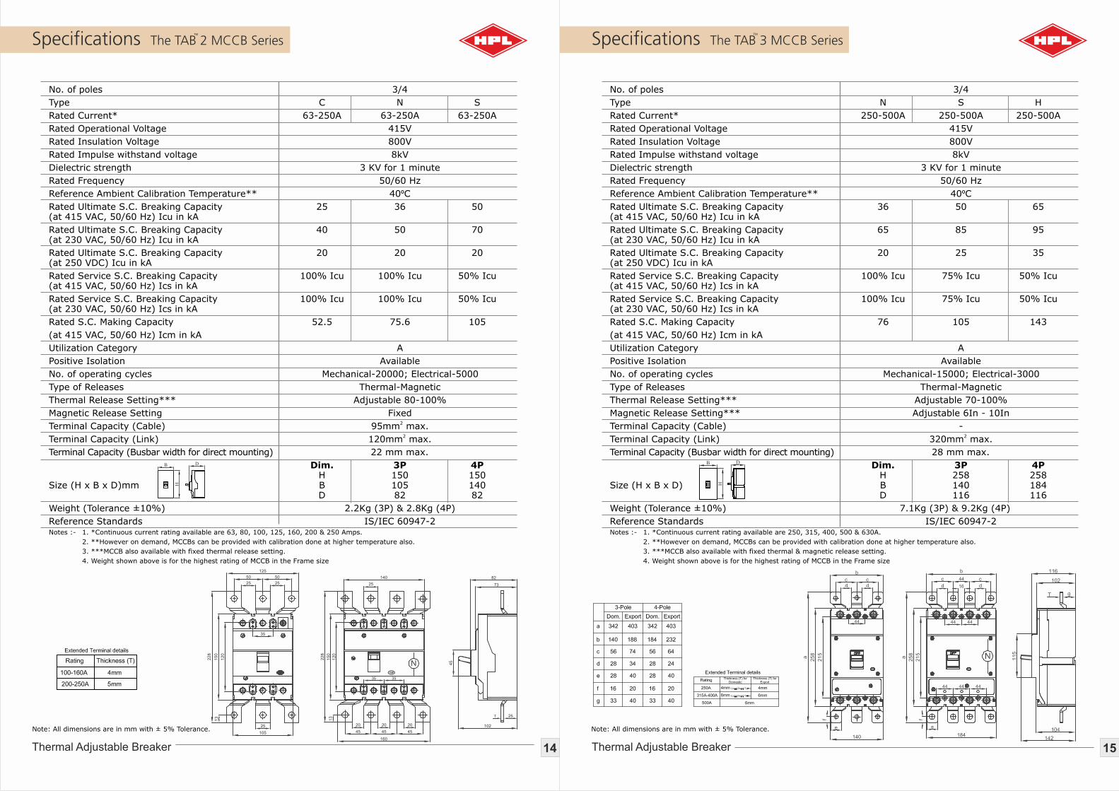
Specifications The TAB 3 MCCB Series
No. of poles 3/4
Type N S H
Rated Current* 250-500A 250-500A 250-500A
Rated Operational Voltage 415V
Rated Insulation Voltage 800V
Rated Impulse withstand voltage 8kV
Dielectric strength 3 KV for 1 minute
Rated Frequency 50/60 Hz
Reference Ambient Calibration Temperature** 40ºC
Rated Ultimate S.C. Breaking Capacity 36 50 65(at 415 VAC, 50/60 Hz) Icu in kA
Rated Ultimate S.C. Breaking Capacity 65 85 95(at 230 VAC, 50/60 Hz) Icu in kA
Rated Ultimate S.C. Breaking Capacity 20 25 35(at 250 VDC) Icu in kA
Rated Service S.C. Breaking Capacity 100% Icu 75% Icu 50% Icu(at 415 VAC, 50/60 Hz) Ics in kA
Rated Service S.C. Breaking Capacity 100% Icu 75% Icu 50% Icu(at 230 VAC, 50/60 Hz) Ics in kA
Rated S.C. Making Capacity 76 105 143
(at 415 VAC, 50/60 Hz) Icm in kA
Utilization Category A
Positive Isolation Available
No. of operating cycles Mechanical-15000; Electrical-3000
Type of Releases Thermal-Magnetic
Thermal Release Setting*** Adjustable 70-100%
Magnetic Release Setting*** Adjustable 6In - 10In
Terminal Capacity (Cable) -2
Terminal Capacity (Link) 320mm max.
Terminal Capacity (Busbar width for direct mounting) 28 mm max.
Dim. 3P 4P H 258 258 Size (H x B x D) B 140 184 D 116 116
Weight (Tolerance ±10%) 7.1Kg (3P) & 9.2Kg (4P)
Reference Standards IS/IEC 60947-2Notes :- 1. *Continuous current rating available are 250, 315, 400, 500 & 630A.
2. **However on demand, MCCBs can be provided with calibration done at higher temperature also.
3. ***MCCB also available with fixed thermal & magnetic release setting.
4. Weight shown above is for the highest rating of MCCB in the Frame size
14Thermal Adjustable Breaker
Specifications The TAB 2 MCCB Series
No. of poles 3/4
Type C N S
Rated Current* 63-250A 63-250A 63-250A
Rated Operational Voltage 415V
Rated Insulation Voltage 800V
Rated Impulse withstand voltage 8kV
Dielectric strength 3 KV for 1 minute
Rated Frequency 50/60 Hz
Reference Ambient Calibration Temperature** 40ºC
Rated Ultimate S.C. Breaking Capacity 25 36 50(at 415 VAC, 50/60 Hz) Icu in kA
Rated Ultimate S.C. Breaking Capacity 40 50 70(at 230 VAC, 50/60 Hz) Icu in kA
Rated Ultimate S.C. Breaking Capacity 20 20 20(at 250 VDC) Icu in kA
Rated Service S.C. Breaking Capacity 100% Icu 100% Icu 50% Icu(at 415 VAC, 50/60 Hz) Ics in kA
Rated Service S.C. Breaking Capacity 100% Icu 100% Icu 50% Icu(at 230 VAC, 50/60 Hz) Ics in kA
Rated S.C. Making Capacity 52.5 75.6 105
(at 415 VAC, 50/60 Hz) Icm in kA
Utilization Category A
Positive Isolation Available
No. of operating cycles Mechanical-20000; Electrical-5000
Type of Releases Thermal-Magnetic
Thermal Release Setting*** Adjustable 80-100%
Magnetic Release Setting Fixed2
Terminal Capacity (Cable) 95mm max.2
Terminal Capacity (Link) 120mm max.
Terminal Capacity (Busbar width for direct mounting) 22 mm max.
Dim. 3P 4P H 150 150Size (H x B x D)mm B 105 140 D 82 82
Weight (Tolerance ±10%) 2.2Kg (3P) & 2.8Kg (4P)
Reference Standards IS/IEC 60947-2Notes :- 1. *Continuous current rating available are 63, 80, 100, 125, 160, 200 & 250 Amps.
2. **However on demand, MCCBs can be provided with calibration done at higher temperature also.
3. ***MCCB also available with fixed thermal release setting.
4. Weight shown above is for the highest rating of MCCB in the Frame size
258
a
215
b
c cd d
44
140
e
f
258
a
215
b
c c
d d
44
16
44 44
44 44 44
184
e
f
228
150
120
125
50 50
25 25
35
25
105
13
228
150
120
140
25
35 35
20 20 20
45 45 45
160
13
82
73
25
102
45
Note: All dimensions are in mm with ± 5% Tolerance. Note: All dimensions are in mm with ± 5% Tolerance.

Characteristic
17Thermal Adjustable Breaker
The TAB Series
Ambient Compensation Curve(TAB-1)
Ambient Compensation Curve (TAB-2)
Ambient Compensation Curve (TAB-3/4)
21 22 23 24 25 26 27 28 29 30
112.5 112 111 110 109.5 109 108 107 106.5 106
Temp.0C
% Comp.
31 32 33 34 35 36 37 38 39 40
105.5 105 104.5 104 103.5 103 102.5 102 101 100
Temp.0C
% Comp.
21 22 23 24 25 26 27 28 29 30
112.5 112 111 110 109.5 109 108 107 106.5 106
Temp.0C
% Comp.
31 32 33 34 35 36 37 38 39 40
105.5 105 104.5 104 103.5 103 102.5 102 101 100
Temp.0C
% Comp.
21 22 23 24
112.5 112 111 110
Temp.0C
% Comp.
31 32 33 34
105.5 105 104.5 104
Temp.0C
% Comp.
25 26 27 28 29 30
109.5 109 108 107 106.5 106
35 36 37 38 39 40
103.5 103 102.5 102 101 100
16Thermal Adjustable Breaker
Specifications The TAB 4 MCCB Series
No. of poles 3/4
Type N S H
Rated Current* 500, 630, 800A
Rated Operational Voltage 415V
Rated Insulation Voltage 800V
Rated Impulse withstand voltage 8kV
Dielectric strength 3 KV for 1 minute
Rated Frequency 50/60 Hz
Reference Ambient Calibration Temperature** 40ºC
Rated Ultimate S.C. Breaking Capacity 36 50 65(at 415 VAC, 50/60 Hz) Icu in kA
Rated Ultimate S.C. Breaking Capacity 65 85 95(at 230 VAC, 50/60 Hz) Icu in kA
Rated Ultimate S.C. Breaking Capacity 20 25 35(at 250 VDC) Icu in kA
Rated Service S.C. Breaking Capacity 100% Icu 75% Icu 50% Icu(at 415 VAC, 50/60 Hz) Ics in kA
Rated Service S.C. Breaking Capacity 100% Icu 75% Icu 50% Icu(at 230 VAC, 50/60 Hz) Ics in kA
Rated S.C. Making Capacity 76 105 143
(at 415 VAC, 50/60 Hz) Icm in kA
Utilization Category A
Positive Isolation Available
No. of operating cycles Mechanical-5000; Electrical-2500
Type of Releases Thermal-Magnetic
Thermal Release Setting*** Adjustable 70-100%
Magnetic Release Setting*** Adjustable 6In - 10In
Terminal Capacity (Cable) -2
Terminal Capacity (Link) 500mm max.
Terminal Capacity (Busbar width for direct mounting) 42 mm max.
Dimensions
Dim. 3P 4PSize (H x B x D) H 280 280 B 210 280 D 120 120
Weight (Tolerance ±10%) 12.4Kg (3P) & 16.2Kg (4P)
Reference Standards IS/IEC 60947-2Notes :- 1. *Continuous current rating available 500, 630 & 800Amps.
2. **However on demand, MCCBs can be provided with calibration done at higher temperature also.
3. ***MCCB also available with fixed thermal & magnetic release setting.
4. Weight shown above is for the highest rating of MCCB in the Frame size
2Hr
1Hr
30 min
20 min
10 min
5 min
2 min
1 min
1000
10000
10
1
0.1
0.01
20
25
32
40
50
63
75
80
90
100
125
160
500
500
500
500
500
800
800
800
1000
1000
1000
1000
Time Current Characteristic Curve (TAB-1)
Time Current Characteristic Curve (TAB-2)
Time Current Characteristic Curve (TAB-3/4)
424
280
250
70 70
25.5 25.5
210
43.5
424
72
395
280
250
280
43.5 25.5
70 70
70 70 70
72.5
120
107
3810
33
154.5
115
Note: All dimensions are in mm with ± 5% Tolerance.
19www.hplindia.com
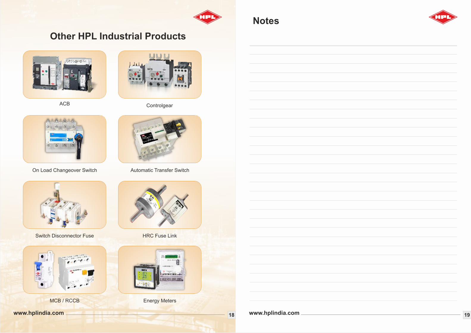
Other HPL Industrial Products
18www.hplindia.com
On Load Changeover Switch Automatic Transfer Switch
Switch Disconnector Fuse HRC Fuse Link
MCB / RCCB Energy Meters
ACB Controlgear
NO13
NC21
NC31
NO43
NO14
NC22
NC32
NO44
IR-22
000142.8RYB
HPL Electric & Power Ltd