s instructions - dellsonics.com d13-d4020050519.pdf · de masse volumique, de pression, de...
TRANSCRIPT

INSTRUCTIONS
English
Introduction
083R
9095
SFIDK.PI.028.P3.52 - A5E00253691
SITRANS F C MASSFLO®®®®® mass flowmetertype MASS 2100, DI 3 - DI 40
083R
9095
Order no.: FDK-521H0999
This instruction covers the mechanical in-stallation and the connection of the sensor tothe signal converter.
Data on the wiring up of the system from theoutputs of MASS 6000 have been stated inthe manual SFIDK.PS.028.M1.02.
Siemens Flow Instruments SITRANS F CMASSFLO® mass flowmeters are units for thedirect measurement of:
• Mass flow rate• Total mass• Density• Temperature• Volumetric flow rate• Total volume• Fraction• % fraction• Total fraction
SITRANS F C MASSFLO® mass flowmetersmeasure the flow direct in kilogrammes, withoutconversion. Measurements are independentof changes in liquid temperature, density,pressure, viscosity, conductivity and flow profile.
With the mass flowmeter it is also possible tomeasure the mass flow of liquids containinghomogeneous mixtures of air and solids.However, large amounts of air may disturb themeasurement.
Measuring accuracyProvided the SITRANS F C MASSFLO® massflowmeter is installed in accordance with theinstructions, it will be unaffected by externaldisturbances and will measure with highaccuracy.The measuring inaccuracy is less than ±0.10%of the measured value, throughout a widemeasuring range.
Precision measuring systemThe mass flowmeter is a precision measuringsystem. It is very robust, but must be handledand installed in accordance with the instruc-tions given.
HandlingThe flowmeter should be handled carefully.In the worst case impact and shock can produceimbalance in the MASS 2100 sensor, withconsequent measuring inaccuracy.
Before commissioning
WarningBefore taking into use this sensor please readthe max. operating pressure (PN) on thesensor label. The operating pressure indicatesthe pressure to which measuring pipe andconnections have been dimensioned.
The enclosure/housing is not rated forpressure containment.
When working with operating pressures/media which in case of pipe fractures maycause injuries to people, equipment or any-thing else, we recommend to take specialprecautions when building-in the sensor i.e.special placement, shielding, pressure re-lease valve or the like.
The sensor enclosure is supplied with a 1/8"nipple. When demounting the nipple, apressure release valve can be connected toautomatically shut off the flow to the sensor incase of leakage. For instructions on themounting, please refer to the section "pres-sure release valve".
Sensor mountingWhen installing a mass flowmeter, it is notnecessary to take account of componentsthat generate turbulence, such as pipe bends,T-pieces, valves, etc. because the meter isnot affected by inlet conditions. However,cavitation and air bubbles in the system candisturb measurements and must be avoided.
Horizontal installation is recommended. Thisavoids solid particles being deposited in themeter and the sensor can be easily emptied.
Ensure that the sensor is not emptied of liquidduring normal operation otherwise incorrectmeasurement will occur.
To ensure optimum operation of the mea-suring equipment it is important that theinstallation instructions are followed pre-cisely.
s
2
SITRANS F C MASSFLO®®®®® mass flowmeter type MASS 2100, DI 3 - DI 40
In dieser Instruktion ist die mechanischeMontage beschrieben sowie der Anschlussvom Messaufnehmer an den Messumformer.
Der elektrische Anschluss der Ausgängevon MASS 6000 ist im ManualSFIDK.PS.028.M1.03 angegeben.
Der Siemens Flow Instruments SITRANS F CMASSFLO® Masse Durchflussmesser ist einSystem für die direkte Messung von:
• Massedurchfluss• Totaler Masse• Dichte• Temperatur• Volumetrischem Durchfluss• Totalem Volumen
Deutsch
Einführung
Denne instruktion beskriver den mekaniskemontage og tilslutning af målehoved tilsignalomsætter.
Elektrisk tilslutning af udgange fra MASS 6000er angivet i manualen SFIDK.PS.028.M1.01.
Siemens Flow Instruments SITRANS F CMASSFLO® masse flowmåler er en flowmålertil direkte måling af:
• Masseflow• Total masse• Massefylde• Temperatur• Volumenflow• Total volumen• Fraktion• % fraktion• Total fraktion
SITRANS F C MASSFLO® masse flowmålerenmåler den gennemstrømmende masse direktei kilogram uden omregning, og målingen eruafhængig af ændringer i væsketemperatur,massefylde, tryk, viskositet, ledningsevne ogflowprofil.
Med masse flowmåleren kan man også målemasseflowet af væsker med homogent for-delte luft- og faststofandele. Større luftansam-linger derimod forstyrrer målingen.
MålenøjagtighedMonteres SITRANS F C MASSFLO® masseflowmåleren i henhold til montageanvisningen,er den upåvirkelig af ydre forstyrrelser og kanmåle med en stor nøjagtighed.Måleunøjagtigheden er mindre end ±0,10% afmålt værdi i et stort måleområde.
PræcisionsmålesystemMasse flowmåleren er et præcisionsmålesys-tem. Trods sin robuste opbygning er det vigtigt,at SITRANS F C MASSFLO® masse flow-måleren behandles og installeres efter an-visning, givet i denne instruktion.
HåndteringFlowmåleren bør behandles forsigtigt.Slag og stød kan i værste fald give anledning tilubalance i målehovedet MASS 2100 medforringet målenøjagtighed til følge.
MonteringVed montering af målehovedet er det ikkenødvendigt at tage hensyn til turbulens-generer-ende komponenter, såsom rørbøjninger, T-stykker, ventiler m.m., idet måleren ikke påvirkesaf, hvordan indløbsforholdene er. Dog skal manundgå kavitation og luftansamlinger i anlægget,da det kan forstyrre målingen.
Det anbefales at montere målehovedet vandret.Derved hindres medførte faststofandele i ataflejres i måleren, og målehovedet kan letteretømmes for væske.
Man bør altid sikre, at målehovedet ikke tømmesfor væske under normal drift, da det medførerfejlmålinger.
For at opnå en optimal funktion af måleudstyreter det vigtigt at følge montageanvisningen punktfor punkt.
Før ibrugtagning
AdvarselFør ibrugtagning af denne sensor, aflæs dadriftstrykket (PN) på sensorskiltet. Driftstrykketangiver det tryk, hvortil målerør og tilslutningerer dimensioneret.
Sensorkappen er ikke dimensioneret somtrykbeholder.
Arbejdes der med driftstryk/medier, der kanvære til fare for mennesker, udstyr eller andetved rørbrud, anbefaler vi, at der ved indbygningaf sensoren tages særlige forholdsregler herfori form af særlig placering, afskærmning, sikker-hedsvagt/ventil eller lignende.Sensorkappen er forsynet med en 1/8" nippelsom kan demonteres hvorefter man kan montereen sikkerhedsvagt/ventil, så der automatisk kanlukkes for flowet til sensoren ved evt. lækage.For montage se afsnittet "sikkerhedsvagt/ventil".
Dansk
Introduktion
• Fraktion• % Fraktion• Totaler Fraktion
SITRANS F C MASSFLO® Masse Durchfluss-messer messen die durchfließende Masse ohnejegliche Umrechnung direkt in Kilogramm,unabhängig von Änderungen der Flüssigkeits-temperatur, der Dichte, des Druckes, derViskosität, der Leitfähigkeit oder des Durch-flussprofils.
Der Masse Durchflussmesser ermöglicht auchdie Messung von Flüssigkeiten mit homogenverteilten Gas- und Feststoffanteilen.Inhomogen verteilte Gaseinschlüsse (Gas-propfen) sind hingegen zu vermeiden.
3
SITRANS F C MASSFLO®®®®® mass flowmeter type MASS 2100, DI 3 - DI 40
Vor der Inbetriebnahme
WarnungLesen Sie bitte vor der Inbetriebnahme diesesMessaufnehmers auf dem Aufnehmer-Typen-schild den max. Betriebsdruck ab. Der Betriebs-druck gibt den Druck an, für den das Messrohrund die Anschlüsse ausgelegt wurden.
Das Gehäuse ist für Druck-Einschluss nichtklassifiziert.
Für das Arbeiten mit Betriebsdrücken/Medien,die bei einem Rohrbruch Personenverletzun-gen, Anlagen- oder Sachschaden verursachenkönnen, empfehlen wir, besondere Vor-kehrungen beim Einbau zu treffen, d.h. einespezielle Lage, Abschirmung, Druckminde-rungsventil oder Ähnliches.
Das Aufnehmergehäuse wird mit einem 1/8"Anschlußnippel geliefert. Wenn man den Nippelabmontiert, kann man ein Druckminderungs-ventil anschließen, um den Fluß zum Aufnehmerbei Leckage automatisch zu unterbrechen.Anleitungen über die Montage finden Sie imAbschnitt „Druckminderungsventil“.
MessgenauigkeitWird der SITRANS F C MASSFLO® MasseDurchflussmesser entsprechend den Mon-tageanweisungen installiert, können äussereStörquellen die hohe Messgenauigkeit nichtbeeinflussen. Die Messgenauigkeit ist dannüber einen grossen Messbereich besser als±0,10% des aktuellen Messwertes.
PräzisionsmesssystemMasse Durchflussmesser sind Präzisionssys-teme. Trotz des robusten Aufbaus ist es wichtig,dass SITRANS F C MASSFLO® Masse Durch-flussmesser entsprechend den Ausführungendieser Instruktion behandelt und installiertwerden.
HandhabungDer Durchflussmesser muss, wie jedesandere Messgerät auch, vorsichtig behandeltwerden.Schläge bzw. Stöße gegen den MessaufnehmerMASS 2100 können Instabilitäten und damitverbundene Ungenauigkeiten hervorrufen.
MontageBei der Montage des Messaufnehmers müssenkeine Ein- und Auslaufstrecken vorgesehenwerden. Turbulenzerzeugende Komponentenwie Rohrbögen, T-Stücke, Ventile usw. beein-flussen die MasseDurchflussmessung nicht.Kavitation und Luftansammlungen in der An-lage muss jedoch vermieden werden, da diesedie Messung stören kann.
Die waagerechte Montage des Durchflussmes-sers wird empfohlen. Dadurch werden Ablage-rungen von mitgeführten Feststoffen im Mess−aufnehmer vermieden, und gleichzeitig ist esleichter, den Messaufnehmer von Flüssigkeitzu entleeren.
Es muss sichergestellt werden, daß der Mess-aufnehmer bei normalem Betrieb nicht vonFlüssigkeit entleert wird, da das zu falschenMessungen führt.
Français
Introduction
Cette feuille d'instructions concerne seule-ment le montage mécanique et le raccord ducapteur au convertisseur de signaux.
Pour le raccordement électrique des sortiesdu MASS 6000 se reporter au manuelsimplifié SFIDK.PS.028.M1.04
Le débitmètre massique SITRANS F CMASSFLO® de Siemens Flow Instruments estconςu pour la mesure directe:
• du débit massique• de la totalisation massique• de la masse volumique• de la température• du débit volumétrique• de la totalisation volumétrique• du fractionnement• du fractionnement en %• de la totalisation fractionnement
Le débitmètre massique SITRANS F CMASSFLO® mesure directement le débitmassique sans correction. La mesure estindépendante de toute variation de température,de masse volumique, de pression, de viscosité,de conductibilité et du profil d’écoulement.
Le débitmètre massique permet également demesurer le débit de fluides contenant en suspen-sion des particules solides et de l’air répartis defaςon homogène. Par contre, de fortes concen-trations d’air perturbent la mesure.
Précision de mesureLorsque le débitmètre massique SITRANS F CMASSFLO® est installé conformément auxinstructions de montage, il est insensible auxperturbations extérieures et mesure avec grandeprécision (les écarts de mesure étant inférieursà ±0,10% de la valeur mesurée, sur une largeplage de mesure).
Um eine sichere Funktion der Messung zu ge-währleisten, sollte die MontageanweisungPunkt für Punkt beachtet werden.
4
SITRANS F C MASSFLO®®®®® mass flowmeter type MASS 2100, DI 3 - DI 40
Système de mesure précisLe débitmètre massique SITRANS F CMASSFLO® constitue un système de mesuretrès précis. Malgré sa conception robuste, il estdonc important qu’il soit manipulé et installéconformément aux indications données.
ManiementLe débitmètre doit être manié avec précautionDes coups ou des chocs peuvent provoquer ladétérioration du MASS 2100.
MontageCe débitmètre massique étant insensible auxperturbations hydrauliques, il est inutile de tenircompte des composants pouvant provo-querdes turbulences tels que coudes, raccords en T,vannes, etc.Par contre, il faut éviter tout risque de cavitationet d’accummulation d’air dans la tuyauterie carcela peut pertuber la mesure.
Toutefois, pour éviter tout dépôt de particules, ilest recommandé de monter le débitmètrehorizontalement. Il est ainsi facile de vidangerle capteur.
Le capteur doit être en charge en fonctionne-ment normal (erreur de mesure).
Pour obtenir le fonctionnement optimal du maté-riel de mesure, il est important de suivre pointpar point les instructions de montage.
Avant la mise en service
ATTENTIONAvant de mettre en service le capteur, veuilleznoter que la pression nominale (PN) indiquéesur la plaque signalétique du capteur est lapression maximale d’utilisation pour le tube demesure et pour les raccords du capteur.
Boîlier non prévu comme enveloppe souspression.
Dans le cas ou vous travaillez à des pressionsélevées ou avec des produits qui peuvent êtredangereux en cas de fuite pour les personnesnous vous recommandons de prendre les me-sures de sécurité adéquate lors du montage dela section de mesure.L’enceinte de confinement possède un bouchonfileté 1/8’’. A la place de ce bouchon on peutmonter une vanne pressostatique et commanderla coupure du débit en cas de fuite du tube demesure. Pour les instructions de montage voirla partie ‘montage pressostat’
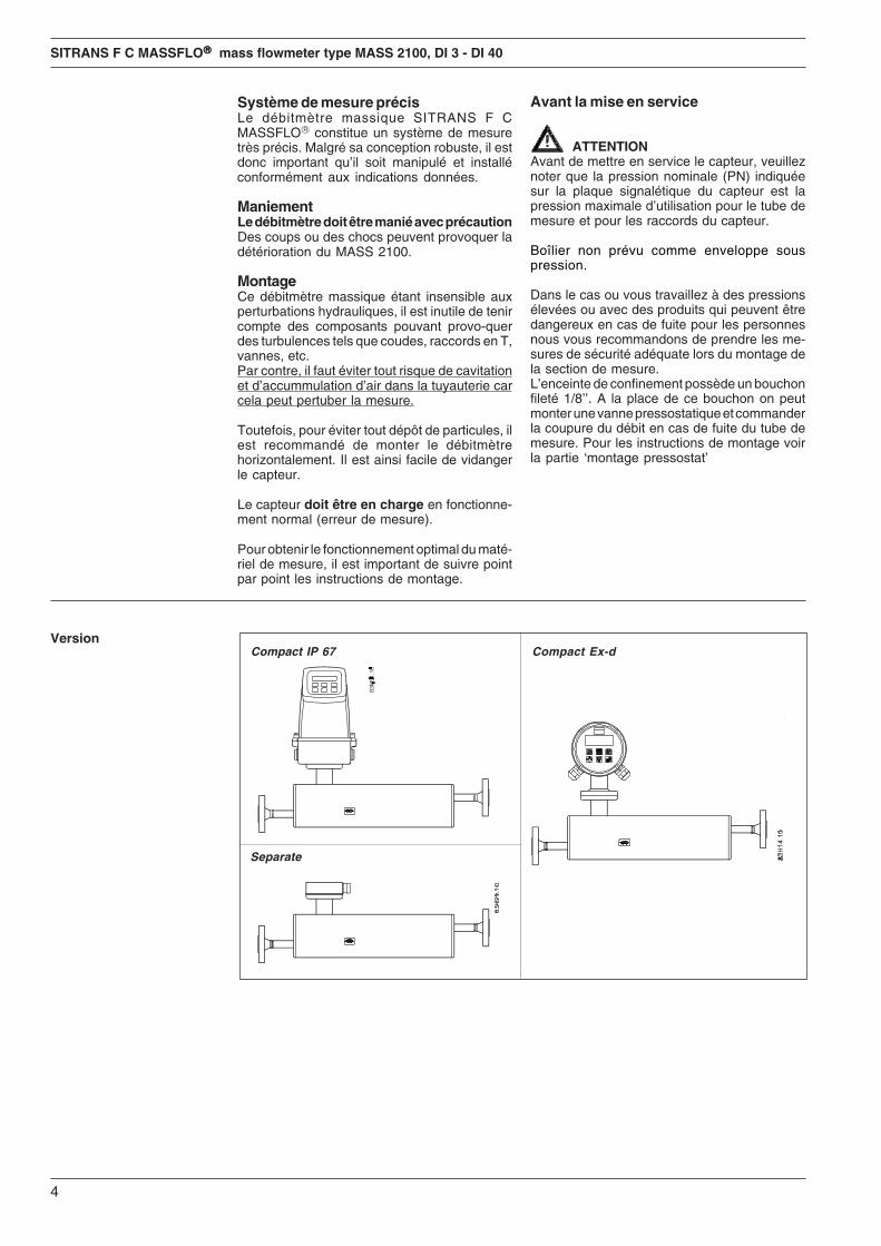
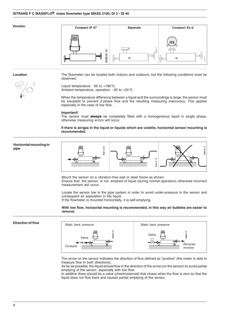
VersionCompact IP 67
Separate
Compact Ex-d
5
SITRANS F C MASSFLO®®®®® mass flowmeter type MASS 2100, DI 3 - DI 40
Location
Placering
Einbau
Emplacement
DeutschDer Durchflussmesser kann sowohl in ge-schlossenen Räumen als auch im Freien an-gebracht werden. Dabei ist jedoch folgendeszu beachten:
Flüssigkeitstemperatur: −50 bis +180°C.Umgebungstemperatur, Betrieb: −20 bis +55°C.
Bei hohen Temperaturunterschieden zwis-chen Flüssigkeit und Umgebung muss derMessaufnehmer isoliert werden, um einen Zwei-phasen Durchfluss und den sich daraus erge-benden Messfehler, insbesondere bei gerin-gem Durchfluss, zu vermeiden.
Wichtig!Der Messaufnehmer muss mit einer ein-phasigen und homogenen Flüssigkeit immergefüllt sein, da sonst zusätzliche Messfehlerauftreten können.
Wenn sich Luft/Gas in der Flüssigkeit befindet,wird empfohlen, den Messaufnehmer waage-recht zu montieren.
FrançaisLe débitmètre peut être installé à l’intérieurcomme à l’extérieur, en respectant les conditionsci-dessous:
Température du fluide: −50 à +180°C.Température ambiante, fonctionnement: −20 à +55°C.
En cas de forte différence de température entrele fluide et l’extérieur, il faut isoler la tête demesure pour éviter l’écoulement diphasique,qui affecterait la précision des mesures, plusparticulièrement en cas de faible débit.
Important!Toujours assurer le remplissage du capteurd'un liquide monophasé ou homogène, sinon ily a des risques d'erreurs de mesure.
Si le fluide contient air/gaz ou liquides volatiles,il est conseillé d’orienter la tête de mesure hori-zontalement.
EnglishThe flowmeter can be located both indoors andoutdoors, but the following conditions must beobserved:
Liquid temperature: −50 to +180°C.Ambient temperature, operation: −20 to +55°C.
When the temperature difference between aliquid and the surroundings is large, the sensormust be insulated to prevent 2-phase flow andthe resulting measuring inaccuracy. This ap-plies especially in the case of low flow.
Important!The sensor must always be completely filledwith a homogeneous liquid in single phase,otherwise measuring errors will occur.
If there is air/gas in the liquid or liquids whichare volatile, horizontal sensor mounting isrecommended.
DanskMåleren kan placeres både inden- og udendørs,blot skal man være opmærksom på følgende:
Væsketemperatur: −50 til +180°C.Omgivelsestemperatur, drift: −20 til +55°C.
Ved store temperaturforskelle imellem væskeog omgivelser skal målehovedet isoleres for atundgå 2-faset flow med måleunøjagtighed tilfølge, specielt ved små flow.
Vigtigt!Målehovedet skal altid være helt fyldt medvæske, som skal være enfaset og homogen,ellers får man målefejl.
Er der luft/gas i væsken, eller er væsken flygtig,anbefales det at montere målehovedet vand-ret.
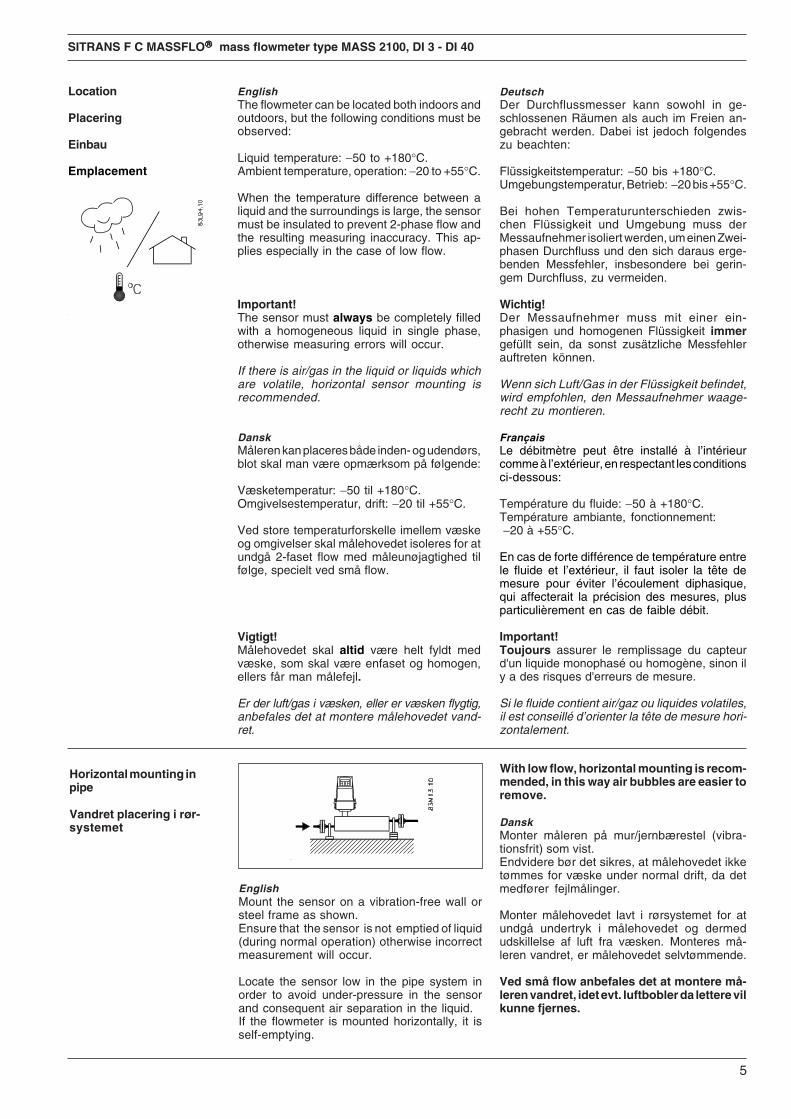
Horizontal mounting inpipe
Vandret placering i rør-systemet
EnglishMount the sensor on a vibration-free wall orsteel frame as shown.Ensure that the sensor is not emptied of liquid(during normal operation) otherwise incorrectmeasurement will occur.
Locate the sensor low in the pipe system inorder to avoid under-pressure in the sensorand consequent air separation in the liquid.If the flowmeter is mounted horizontally, it isself-emptying.
With low flow, horizontal mounting is recom-mended, in this way air bubbles are easier toremove.
DanskMonter måleren på mur/jernbærestel (vibra-tionsfrit) som vist.Endvidere bør det sikres, at målehovedet ikketømmes for væske under normal drift, da detmedfører fejlmålinger.
Monter målehovedet lavt i rørsystemet for atundgå undertryk i målehovedet og dermedudskillelse af luft fra væsken. Monteres må-leren vandret, er målehovedet selvtømmende.
Ved små flow anbefales det at montere må-leren vandret, idet evt. luftbobler da lettere vilkunne fjernes.
6
SITRANS F C MASSFLO®®®®® mass flowmeter type MASS 2100, DI 3 - DI 40
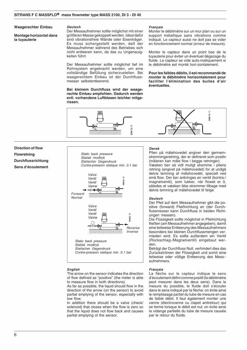
DeutschDer Messaufnehmer sollte möglichst mit einergrößeren Masse gekoppelt werden. Ideal dafürsind vibrationsfreie Wände oder Eisenträger.Es muss sichergestellt werden, daß derMessaufnehmer während des Betriebes sichnicht entleeren kann, da das zu Ungenauig-keiten führt.
Der Messaufnehmer sollte möglichst tief imRohrsystem angebracht werden, um einevollständige Befüllung sicherzustellen. Beiwaagerechtem Einbau ist der Durchfluss-messer selbstentleerend.
Bei kleinem Durchfluss wird der waage-rechte Einbau empfohlen. Dadurch werdenevtl. vorhandene Luftblasen leichter mitge-rissen.
Direction of flow
Flowretning
Durchflussrichtung
Sens d’écoulement
Static back pressureStatisk modtrykStatischer GegendruckContre-pression statique min. 0.1 bar
Static back pressureStatisk modtrykStatischer GegendruckContre-pression statique min. 0.1 bar
EnglishThe arrow on the sensor indicates the directionof flow defined as “positive” (the meter is ableto measure flow in both directions).As far as possible, the liquid should flow in thedirection of the arrow (on the sensor) to avoidpartial emptying of the sensor, especially withlow flow.In addition there should be a valve (check/solenoid) that closes when the flow is zero sothat the liquid does not flow back and causespartial emptying of the sensor.
ValveVentilVentilVanne
ReverseInverse
ForwardNormal
DanskPilen på målehovedet angiver den gennem-strømningsretning, der er defineret som positiv(måleren kan måle flow i begge retninger).Væsken bør så vidt muligt strømme i pilensretning (angivet på målehovedet) for at undgådelvis tømning af målehovedet, specielt vedsmå flow. Der bør anbringes en ventil (kontra-/magnetventil), som lukker, når flowet er 0,således at væsken ikke strømmer tilbage meddelvis tømning af målehovedet til følge.
DeutschDer Pfeil auf dem Messaufnehmer gibt die po-sitive (forward) Fließrichtung an (der Durch-flussmesser kann Durchfluss in beiden Richt-ungen messen).Die Flüssigkeit sollte möglichst in Pfeilrichtungfließen (am Messaufnehmer angegeben), damiteine teilweise Entleerung des Messaufnehmersbesonders bei kleinen Durchflussmengen ver-mieden wird. Es sollte außerdem ein Ventil(Rückschlag-/Magnetventil) eingebaut wer-den.Beträgt der Durchfluss Null, verhindert dies dasZurückströmen der Flüssigkeit und somit eineteilweise oder völlige Entleerung des Mess−aufnehmers.
FrançaisLa flèche sur le capteur indique le sensd’écoulement défini comme positif (le débitmètrepeut mesurer dans les deux sens). Dans lamesure du possible, le fluide doit s’écoulerdans le sens indiqué par la flèche: on évite ainsile remplissage partiel du tube de mesure en casde faible débit. Il faut également monter unevanne (électrovanne ou clapet antiretour) quise ferme lorsque le débit est nul; on évite ainsila vidange partielle du tube de mesure causéepar le retour du fluide.
ValveVentilVentilVanne
Waagerechter Einbau
Montage horizontal dansla tuyauterie
FrançaisMonter le débitmètre sur un mur plan ou sur unsupport métallique sans vibrations commeindiqué. Le capteur aussi ne doit pas se videren fonctionnement normal (erreur de mesure).
Monter le capteur dans un point bas de latuyauterie pour éviter un éventuel dégazage dufluide. Le capteur se vide auto-matiquement sile débitmètre est monté hori-zontalement.
Pour les faibles débits, il est recommandé demonter le débitmètre horizontalement pourfaciliter l’élimination des bulles d’airéventuelles.
7
SITRANS F C MASSFLO®®®®® mass flowmeter type MASS 2100, DI 3 - DI 40
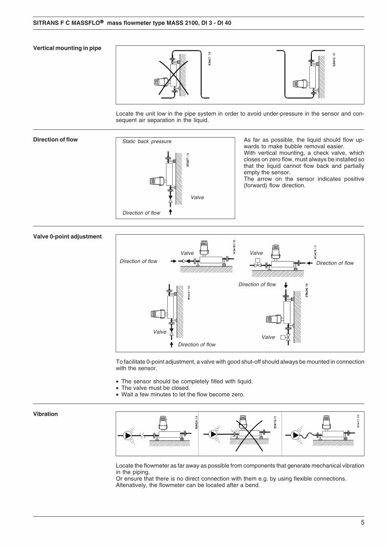
Vertical mounting in pipe
Lodret placering i rør-systemet
Senkrechter Einbau
Montage vertical dans latuyauterie
EnglishLocate the unit low in the pipe system in orderto avoid under-pressure in the sensor and con-sequent air separation in the liquid.
DanskMonter måleren lavt i rørsystemet for at undgåundertryk i målehovedet og dermed udskillelseaf luft fra væsken.
DeutschDer Durchflussmesserr sollte möglichst tief imRohrsystem angebracht werden, um eine voll-ständige Befüllung sicherzustellen.
FrançaisMonter le débitmètre en point bas dans latuyauterie afin d’éviter un dégazage dans la têtede mesure.
Direction of flow
Flowretning
Durchflussrichtung
Sens d'écoulement
DanskVæsken bør så vidt muligt strømme nedefra ogopefter for lettere at fjerne evt. luftbobler.Ved lodret montage skal der altid være anbragten ventil (kontraventil), som lukker, når flowet er0, således at mediet ikke strømmer tilbage meddelvis tømning af målehovedet til følge. Pilen påmålehovedet angiver positiv (forward) flow-retning.
DeutschDer Durchfluss sollte von unten nach oben er-folgen. Dadurch werden eventuell vorhandeneLuftblasen im Messaufnehmer leichter mitge-rissen.Bei senkrechter Montage muss darauf geachtetwerden, dass z.B. bei Dosier-Ende keine Flüssig-keit zurückfließt und damit Teilfüllung imMessauf-nehmer entsteht.Der Pfeil auf dem Messaufnehmer gibt die po-sitive (forward) Durchflussrichtung an.
FrançaisSi possible, le fluide doit s’écouler de bas enhaut afin d’éliminer les bulles d’air éventuelles.En cas de montage vertical, il faut toujoursmonter une vanne (clapet antiretour) qui seferme à débit nul pour empêcher le fluide derefluer, ce qui viderait partiellement le capteur.La flèche sur le capteur indique le sens positif(normal) d’écoulement du fluide.
Static back pressureStatisk modtrykStatischer GegendruckContre-pression statiquemin. 0.1-0.2 bar
ValveVentilVentil(Rückschlag-ventil usw.)Vanne
Direction of flowFlowretningDurchflussrichtungSens d'écoulement
EnglishAs far as possible, the liquid should flow up-wards to make bubble removal easier.With vertical mounting, a check valve, whichcloses on zero flow, must always be installed sothat the liquid cannot flow back and partiallyempty the sensor.The arrow on the sensor indicates positive(forward) flow direction.
Valve 0-point adjustment
Ventil 0-punktsjustering
Nullpunktkalibrierung
Utilisation de vannes pourl'étalonnage du point zéro
ValveVentilVentilVanne
ValveVentilVentilVanne
Direction of flowFlowretningDurchflussrichtungSens d'écoulement
Direction of flowFlowretningDurchflussrichtungSens d'écoulement
Direction of flowFlowretningDurchflussrichtungSens d'écoulement
ValveVentilVentilVanne
Direction of flowFlowretningDurchflussrichtungSens d'écoulement
ValveVentilVentilVanne
8
SITRANS F C MASSFLO®®®®® mass flowmeter type MASS 2100, DI 3 - DI 40
EnglishTo facilitate 0-point adjustment, a valve withgood shut-off should always be mounted inconnection with the sensor.• The sensor should be completely filled with
liquid.• The valve must be closed.• Wait a few minutes to let the flow become
zero.
DanskDer bør altid anbringes en tætsluttende ventil iforbindelse med målehovedet til 0-punkts-justering.• Målehovedet skal være helt fyldt.• Ventilen skal være helt lukket.• Vent et par minutter for at flowet bliver lig nul.
DeutschUm den Nullpunktabgleich zu erleichtern, solltenzwingend Absperrventile vor und nach demMessaufnehmer eingebaut werden. Vor derEinstellung des Nullpunktes ist darauf zu achten, daß• der Messaufnehmer völlig mit Medium gefüllt
ist.• vorhandene Absperrventile geschlossen sind• das Medium im Aufnehmer absolut keinen
MassenDurchfluss zeigt (Null-Durchfluss).
FrançaisPour l’étalonnage du point zéro, il est préférablede monter près du capteur une vanne fermanthermétiquement.• Le capteur doit être entièrement rempli de liquide• Les vannes doivent être correctement fermées.• Attendez quelques minutes pour que le débit
soit bien à zero.
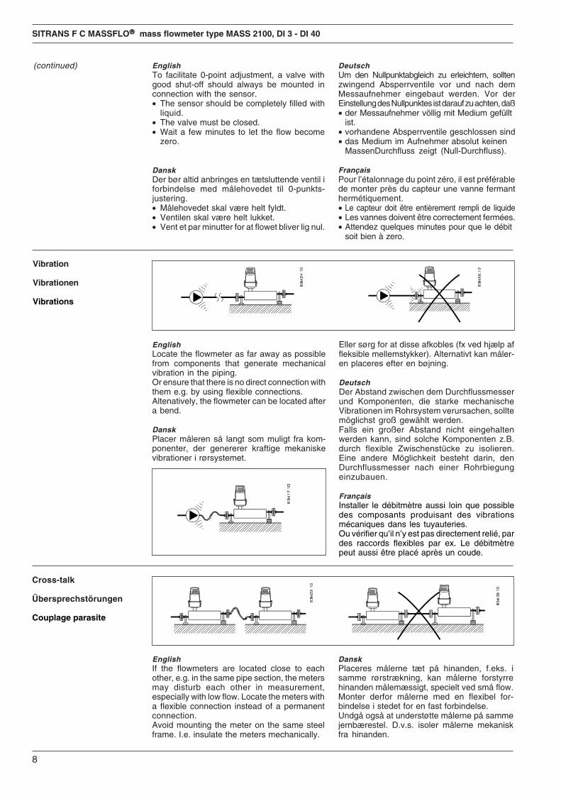
Vibration
Vibrationen
Vibrations
EnglishLocate the flowmeter as far away as possiblefrom components that generate mechanicalvibration in the piping.Or ensure that there is no direct connection withthem e.g. by using flexible connections.Altenatively, the flowmeter can be located aftera bend.
DanskPlacer måleren så langt som muligt fra kom-ponenter, der genererer kraftige mekaniskevibrationer i rørsystemet.
Eller sørg for at disse afkobles (fx ved hjælp affleksible mellemstykker). Alternativt kan måler-en placeres efter en bøjning.
DeutschDer Abstand zwischen dem Durchflussmesserund Komponenten, die starke mechanischeVibrationen im Rohrsystem verursachen, solltemöglichst groß gewählt werden.Falls ein großer Abstand nicht eingehaltenwerden kann, sind solche Komponenten z.B.durch flexible Zwischenstücke zu isolieren.Eine andere Möglichkeit besteht darin, denDurchflussmesser nach einer Rohrbiegungeinzubauen.
FrançaisInstaller le débitmètre aussi loin que possibledes composants produisant des vibrationsmécaniques dans les tuyauteries.Ou vérifier qu’il n’y est pas directement relié, pardes raccords flexibles par ex. Le débitmètrepeut aussi être placé après un coude.
Cross-talk
Übersprechstörungen
Couplage parasite
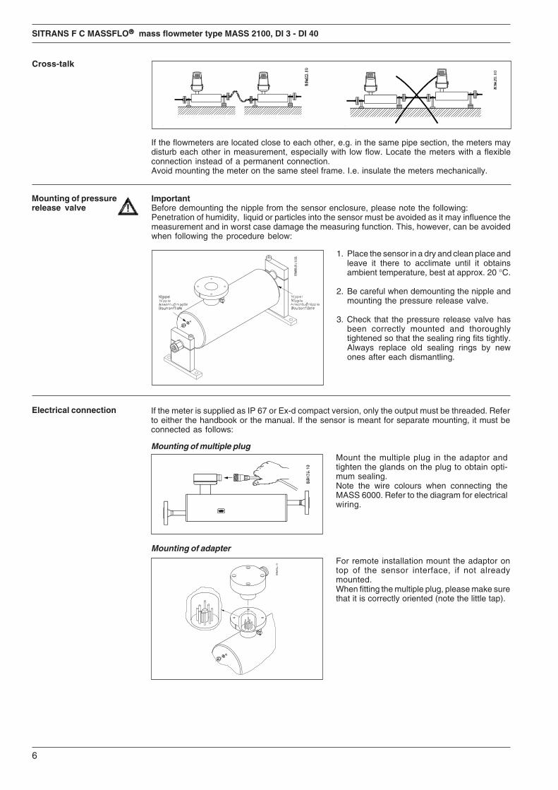
EnglishIf the flowmeters are located close to eachother, e.g. in the same pipe section, the metersmay disturb each other in measurement,especially with low flow. Locate the meters witha flexible connection instead of a permanentconnection.Avoid mounting the meter on the same steelframe. I.e. insulate the meters mechanically.
(continued)
DanskPlaceres målerne tæt på hinanden, f.eks. isamme rørstrækning, kan målerne forstyrrehinanden målemæssigt, specielt ved små flow.Monter derfor målerne med en flexibel for-bindelse i stedet for en fast forbindelse.Undgå også at understøtte målerne på sammejernbærestel. D.v.s. isoler målerne mekaniskfra hinanden.
9
SITRANS F C MASSFLO®®®®® mass flowmeter type MASS 2100, DI 3 - DI 40
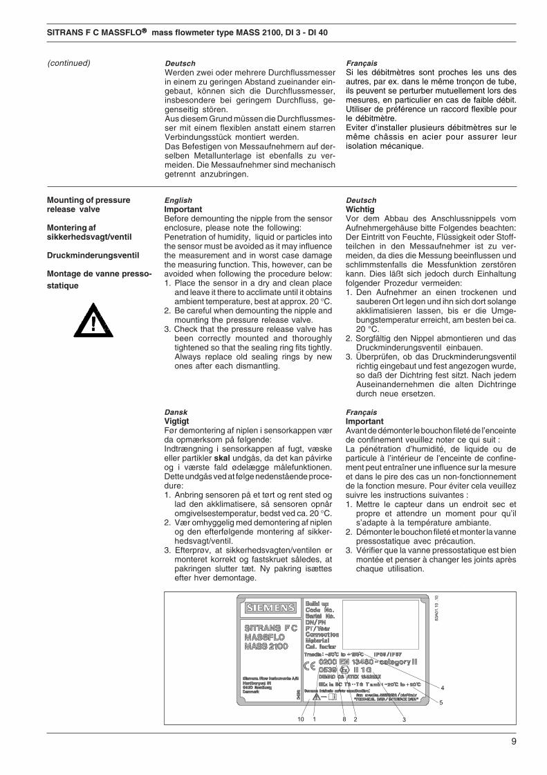
Mounting of pressurerelease valve
Montering afsikkerhedsvagt/ventil
Druckminderungsventil
Montage de vanne presso-statique
EnglishImportantBefore demounting the nipple from the sensorenclosure, please note the following:Penetration of humidity, liquid or particles intothe sensor must be avoided as it may influencethe measurement and in worst case damagethe measuring function. This, however, can beavoided when following the procedure below:1. Place the sensor in a dry and clean place
and leave it there to acclimate until it obtainsambient temperature, best at approx. 20 °C.
2. Be careful when demounting the nipple andmounting the pressure release valve.
3. Check that the pressure release valve hasbeen correctly mounted and thoroughlytightened so that the sealing ring fits tightly.Always replace old sealing rings by newones after each dismantling.
DanskVigtigtFør demontering af niplen i sensorkappen værda opmærksom på følgende:Indtrængning i sensorkappen af fugt, væskeeller partikler skal undgås, da det kan påvirkeog i værste fald ødelægge målefunktionen.Dette undgås ved at følge nedenstående proce-dure:1. Anbring sensoren på et tørt og rent sted og
lad den akklimatisere, så sensoren opnåromgivelsestemperatur, bedst ved ca. 20 °C.
2. Vær omhyggelig med demontering af niplenog den efterfølgende montering af sikker-hedsvagt/ventil.
3. Efterprøv, at sikkerhedsvagten/ventilen ermonteret korrekt og fastskruet således, atpakringen slutter tæt. Ny pakring isættesefter hver demontage.
DeutschWerden zwei oder mehrere Durchflussmesserin einem zu geringen Abstand zueinander ein-gebaut, können sich die Durchflussmesser,insbesondere bei geringem Durchfluss, ge-genseitig stören.Aus diesem Grund müssen die Durchflussmes-ser mit einem flexiblen anstatt einem starrenVerbindungsstück montiert werden.Das Befestigen von Messaufnehmern auf der-selben Metallunterlage ist ebenfalls zu ver-meiden. Die Messaufnehmer sind mechanischgetrennt anzubringen.
(continued) FrançaisSi les débitmètres sont proches les uns desautres, par ex. dans le même tronçon de tube,ils peuvent se perturber mutuellement lors desmesures, en particulier en cas de faible débit.Utiliser de préférence un raccord flexible pourle débitmètre.Eviter d’installer plusieurs débitmètres sur lemême châssis en acier pour assurer leurisolation mécanique.
DeutschWichtigVor dem Abbau des Anschlussnippels vomAufnehmergehäuse bitte Folgendes beachten:Der Eintritt von Feuchte, Flüssigkeit oder Stoff-teilchen in den Messaufnehmer ist zu ver-meiden, da dies die Messung beeinflussen undschlimmstenfalls die Messfunktion zerstörenkann. Dies läßt sich jedoch durch Einhaltungfolgender Prozedur vermeiden:1. Den Aufnehmer an einen trockenen und
sauberen Ort legen und ihn sich dort solangeakklimatisieren lassen, bis er die Umge-bungstemperatur erreicht, am besten bei ca.20 °C.
2. Sorgfältig den Nippel abmontieren und dasDruckminderungsventil einbauen.
3. Überprüfen, ob das Druckminderungsventilrichtig eingebaut und fest angezogen wurde,so daß der Dichtring fest sitzt. Nach jedemAuseinandernehmen die alten Dichtringedurch neue ersetzen.
FrançaisImportantAvant de démonter le bouchon fileté de l’enceintede confinement veuillez noter ce qui suit :La pénétration d’humidité, de liquide ou departicule à l’intérieur de l’enceinte de confine-ment peut entraîner une influence sur la mesureet dans le pire des cas un non-fonctionnementde la fonction mesure. Pour éviter cela veuillezsuivre les instructions suivantes :1. Mettre le capteur dans un endroit sec et
propre et attendre un moment pour qu’ils’adapte à la température ambiante.
2. Démonter le bouchon fileté et monter la vannepressostatique avec précaution.
3. Vérifier que la vanne pressostatique est bienmontée et penser à changer les joints aprèschaque utilisation.
10
SITRANS F C MASSFLO®®®®® mass flowmeter type MASS 2100, DI 3 - DI 40
EnglishFor remote installation mount the adaptor ontop of the sensor interface, if not alreadymounted.When fitting the multiple plug, please make surethat it is correctly oriented (note the little tap).
Mounting of adapter
Montering af adaptor
Montage des Adapters
Montage de l’adaptateur
EnglishMount the multiple plug in the adaptor andtighten the glands on the plug to obtain opti-mum sealing.Note the wire colours when connecting theMASS 6000. Refer to the diagram for electricalwiring.
Mounting of multiple plug
Montering af multistik
Multistecker-Einbau
Montage du connecteur
Electrical connection
Elektrisk tilslutning
Elektrischer Anschluß
Raccordement électrique
EnglishIf the meter is supplied as IP 67 or Ex-d compactversion, only the output must be threaded.Refer to either the Product Manual or the QuickStart Manual. If the sensor is meant for separatemounting, it must be connected as follows:
DanskHvis måleren leveres som IP 67 eller Ex-dkompakt version kræves kun fortrådning afudgangen jvt. produkt manualen/quick startmanualen. Leveres sensoren til separatmontering skal sensoren forbindes således:
DeutschWenn der Massen-Durchflussmesser als kom-pakte IP 67 oder kompakte Ex-d Version geliefertwird, müssen lediglich die Ausgänge verschaltetwerden. Hinweise hierfür entnehmen Sieentweder dem Produkthandbuch oder demQuick-Start-Manual. Ist der Massen-Durchfluss-messer für den getrennten Einbau vorgesehen,muss wie folgt verschaltet werden:
FrançaisSi le capteur est livré en version IP 67 ou enversion Ex-d compact, seules les sorties peuventêtre utilisées. Se référer au manuel produit ouau manuel simplifié. Si le capteur est utilisé enversion séparé, il doit être monté comme ciaprès.
DanskMonter multistikket i adaptoren og spændforskruningerne på stikket for at opnå optimaltæthed.Vær opmærksom på ledningsfarven, når MASS6000 forbindes. Se venligst ledningsdiagrammetfor korrekt elektrisk tilslutning.
DeutschDen Multistecker mit dem Anschlußadapterverbinden. Die Verschraubung am Stecker festanziehen um den einwandfreien Kontaktherzustellen. Beachten Sie die Farbcodierungdes Kabels beim Anschluß des MASS 6000.Hinweise hierfür im elektrischen Anschlußplan.
FrançaisInstaller le connecteur sur l’adaptateur et levisser avec précaution pour obtenir l’étanchéitémaximun.Noter la couleur des fils lors du cablage du mass6000 et se référer au schema éléctrique.
DanskVed separat montage skal adaptoren mon-teres ovenpå sensor interfacet, hvis den ikkeallerede er monteret. Når multistikket fast-gøres, bør det sikres, at stikket vender korrekt(bemærk den lille tap).
DeutschZur getrennten Montage den Adapter oben amMessaufnehmer montieren, wenn dies nichtschon werkseitig geschehen ist.Den Multistecker beim Verbinden korrektpositionieren (Führungsnut beachten).
FrançaisPour la version montage séparé, monterl’adaptateur sur le capteur, si cela n’est pas déjafait.Lors du montage du connecteur, vérifier qu’il estcorrectement positionné (voir la petite marque).

11
SITRANS F C MASSFLO®®®®® mass flowmeter type MASS 2100, DI 3 - DI 40
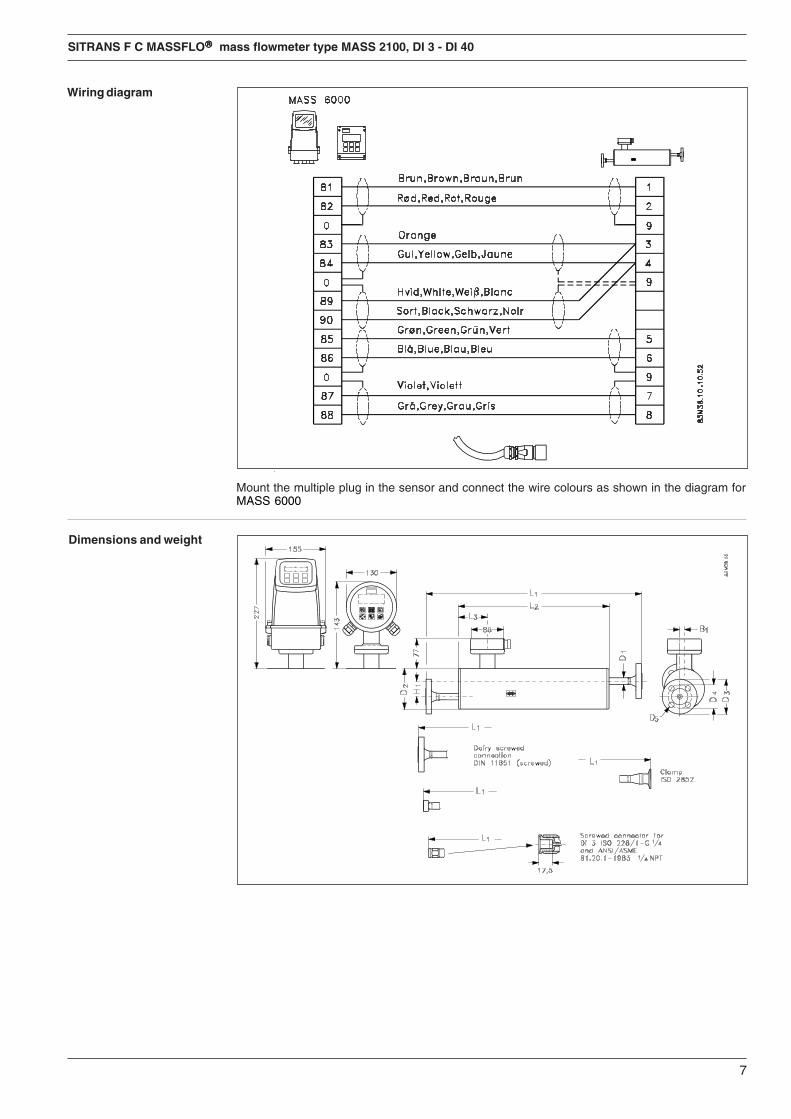
Wiring diagram
Forbindelsesdiagram
Schaltdiagramm
Diagramme de montage
EnglishMount the multiple plug in the sensor and connect the wire colours as shown in the diagram forMASS 6000
DanskMonter multistikket i målehovedet og forbind ledningsfarverne som vist i diagrammet til MASS6000.
DeutschBitte den Multistecker auf den Messaufnehmer montieren und dann die entsprechenden Farb-leitungen anschließen, so wie es aus dem Diagramm für MASS 6000 hervorgeht.FrançaisVisser le connecteur sur le capteur et raccorder le selon le schéma de câblage pour MASS 6000.
Dimensions and weight

12
SITRANS F C MASSFLO®®®®® mass flowmeter type MASS 2100, DI 3 - DI 40
L1 L2 L3 H1 B1 D1 D2 D3 D4 D5Type Pressure rating Size mm mm mm mm mm mm mm mm mm mm
DI 3 Pipe thread ISO 228/1 -PN 100 1/4" 400 280 75.0 60 0 21.3 104 - - -G 1/4
Pipe thread ANSI/ASMEPN 100 1/4" 400 280 75.0 60 0 21.3 104 - - -B 1.20.1 - 1/4" NPT
DI 6 Flange DIN 2635 PN 40 DN 10 560 390 62.0 40 12 17.0 104 90.0 60.0 14.0Flange ANSI B 16.5 CLASS 150 1/2" 624 390 62.0 40 12 17.0 104 88.9 60.5 15.7Flange ANSI B 16.5 CLASS 600 1/2" 608 390 62.0 40 12 17.0 104 95.3 66.5 15.7Screwed connection DIN 11851 PN 40 DN 10 532 390 62.0 40 12 17.0 104 - - -Clamp ISO 2852 PN 16 25 mm 570 390 62.0 40 12 17.0 104 - - -
DI 15 Flange DIN 2635 PN 40 DN 15 620 444 75.0 44 20 21.3 129 95.0 65.0 14.0Flange ANSI B 16.5 CLASS 150 1/2" 639 444 75.0 44 20 21.3 129 88.9 60.5 15.7Flange ANSI B 16.5 CLASS 600 1/2" 660 444 75.0 44 20 21.3 129 95.3 66.5 15.7Screwed connection DIN 11851 PN 40 DN 15 586 444 75.0 44 20 21.3 129 - - -Clamp ISO 2852 PN 16 25 mm 624 444 75.0 44 20 21.3 129 - - -
DI 25 Flange DIN 2635 PN 40 DN 25 934 700 74.5 126 25 33.7 219 115.0 85.0 14.0Flange ANSI B 16.5 CLASS 150 1" 967 700 74.5 126 25 33.7 219 108.0 79.2 15.7Flange ANSI B 16.5 CLASS 600 1" 992 700 74.5 126 25 33.7 219 124.0 88.9 19.1Screwed connection DIN 11851 PN 40 DN 32 922 700 74.5 126 25 33.7 219 - - -Clamp ISO 2852 PN 16 38 mm 940 700 74.5 126 25 33.7 219 - - -
DI 40 Flange DIN 2635 PN 40 DN 40 1064 850 71.5 180 0 48.3 273 150.0 110.0 18.0Flange ANSI B 16.5 CLASS 150 11/2" 1100 850 71.5 180 0 48.3 273 127.0 98.6 15.7Flange ANSI B 16.5 CLASS 600 11/2" 1128 850 71.5 180 0 48.3 273 155.4 114.3 22.4Screwed connection DIN 11851 PN 25 DN 50 1090 850 71.5 180 0 48.3 273 - - -Clamp ISO 2852 PN 16 51 mm 1062 850 71.5 180 0 48.3 273 - - -
Sensorsize
Connections
L5 L3 H3 B2 D6 D7 D8Flange Pressure rating Size mm mm mm mm mm mm mm
DI 3 DIN 2635 PN 40 DN 15 234 75.0 122.0 22.0 95.0 65.0 14.0ANSI B16.5 CLASS 150 1/2" 234 75.0 131.6 22.0 88.9 60.5 15.7
DI 6 DIN 2635 PN 40 DN 15 234 62.0 112.0 22.7 95.0 65.0 14.0ANSI B16.5 CLASS 150 1/2" 234 62.0 121.6 22.7 88.9 60.5 15.7
DI 15 DIN 2635 PN 40 DN 15 234 75.0 126.5 31.5 95.0 65.0 14.0ANSI B16.5 CLASS 150 1/2" 234 75.0 136.1 31.5 88.9 60.5 15.7
DI 25 DIN 2635 PN 40 DN 15 420 74.5 213.6 60 95.0 65.0 14.0ANSI B16.5 CLASS 150 1/2" 420 74.5 223.2 60 88.9 60.5 15.7
DI 40 DIN 2635 PN 40 DN 15 500 71.5 267.5 43 95.0 65.0 14.0ANSI B16.5 CLASS 150 1/2" 500 71.5 277.1 43 88.9 60.5 15.7
Sensor MASS 2100 with "heating jacket"
Sensorsize
ConnectionsHeated
We have checked the contents of this manual for agreement with the hardware andsoftware described. Since deviations cannot be precluded entirely, we cannot guaranteefull agreement. However, the data in this manual are reviewed regularly and anynecessary corrections included in subsequent editions. Suggestions for improvementare always welcomed.
Technical data subject to change without prior notice.
The reproduction, transmission or use of this document or its contents is not permitted withoutexpress written authority.Offenders will be liable for damages. All rights, including rights created by patent grant orregistration of a utility model or design, are reserved.
Copyright © Siemens AG 04.2005 All Rights Reserved
Siemens Flow Instruments A/SNordborgvej 81DK-6430 Nordborg
Order no.: FDK:521H0999-02Printed in: Denmark
INSTRUCTIONS
Introduction
Ap
pen
dix
to
083
R90
95
SFIDK.PI.028.P4.02 - A5E00253691
SITRANS F C MASSFLO®®®®® mass flowmetertype MASS 2100, DI 3 - DI 40
Ap
pen
dix
to
083
R90
95
Scope This instruction covers the mechanical installation and safety guidelines related to the MASS2100 sensor programme DI 3 -DI 40, together with a wiring diagram between sensor andconverter.
SITRANS F C MASSFLO® mass flowmeters measures the flow direct in kilogrammes, withoutconversion. Measurements are independent of changes in liquid temperature, density,pressure, viscosity, conductivity and flow profile.
With the mass flowmeter it is also possible to measure the mass flow of liquids containinghomogeneous mixtures of air and solids. However, large amounts of air may disturb themeasurement.
For saftety reasons and to achieve the specified performance the SITRANS F C MASSFLO®
mass flowmeter must be handled and installed in accordance with the instructions given.
• Installation, connection, commissioning and service must be carried out by personnelwho are qualified and authorized to do so.
• It is very important that the same people have read and understand the instructions anddirections provided in this instruction and that they follow the instructions and directionsbefore taking the equipment into use!
• People who are authorized and trained by the owner of the equipment may operate theequipment.
• The installation must ensure that the measuring system is correctly connected and is inaccordance with the connection diagram. The signal converter has to be earthed unlessthe power supply is galvanically isolated.
• In applications with working pressures/media that can be dangerous to people, surroundings,equipment or others in case of pipe fracture, we recommend that special precautions suchas special placement, shielding or installation of a security guard or a security valve shouldbe made when the sensor is being installed.The enclosure/housing is not rated for pressure containment.
• Siemens Flow Instruments want to assist by estimating the chemical resistance of thesensor parts that are in connection with the media, but it is at any time the customer’sresponsibility, which materials are chosen and Siemens Flow Instruments takes noresponsibility if the sensor corrodes!
• Equipment used in hazardous areas must be Ex-approved and marked for Europe andUL for USA.It is required that the special directions provided in the manual and in the Ex certificate mustbe followed!
• Installation of the equipment must comply with national regulations.Example EN 60079-14 for Denmark.
• Repair and service can be done by approved Siemens Flow Instruments personnel only.
• The p/T ratings indicate the relationship between the maximum allowable pressure PS andthe maximum allowable temperature.
Handling The flowmeter should be handled carefully.The mass flowmeter is a precision measuring system and should be handled with care duringtransportation and installation. During transportation the sensor should remain in the originalSiemens Flow Instruments transportation box. In the worst case impact and shock can produceimbalance or mechanical fractures in the MASS 2100 sensor, with consequent measuringinaccuracy or hazards with respect to people and environment.
s
Order no.: FDK-521H0999
2
SITRANS F C MASSFLO®®®®® mass flowmeter type MASS 2100, DI 3 - DI 40
Application conditions/limi-tations
The sensor must not be used outside the specifications given on the TAG label on the sensor andthe data given in the handbook, SFIDK.PS.028.L1.02.
Permissible pressure(PS/PN)
Before taking the sensor into use please read the max. operating pressure (PN) on the sensorTAG. The operating pressure indicates the pressure to which measuring pipe and connectionshave been dimensioned and pressure tested. This, however, is not the case with the sensorenclosure (i.e. the enclosure covering the measuring pipe).The enclosure/housing is not rated for pressure containment.
When working with operating pressures/media which in case of pipe fractures may cause injuriesto people, equipment or anything else, we recommend to take special precautions when building-in the sensor i.e. special placement, shielding, pressure release valve or the like.
The sensor enclosure is supplied with a 1/8" nipple. When demounting the nipple, a pressurerelease valve can be connected to automatically shut off the flow to the sensor in case of leakage.For instructions on the mounting, please refer to the section ”pressure release valve”.
Cavitation/pressureschoks
When installing a mass flowmeter, it is not necessary to take account of components that generateturbulence, such as pipe bends, T-pieces, valves, etc. because the meter is not affected by inletconditions. However, cavitation and air bubbles in the system can disturb measurements andmust be avoided. Heavy pressure shocks (water hammers) must be avoided as they will disturbmeasurement and can damage the sensor, dependant of energy in the pressure shock.
Permissible temperature(TS)
The minimum and maximum temperature rating given on the sensor TAG must not be exceeded.
Corrosive liquids andgases
Before taking the sensor into use please ensure that the sensor material can withstand possiblecorrosion forces that might occur from the liquid or gas in question. This also covers cleaningagents or CIP liquids (Cleaning In Place), which might be used on a non, frequent basis.From the sensor TAG the pipe material are listed according to the EN 13480.Further material fatigue from abrasive wear due to wearing particles in the liquid must be avoided.
Pressure Equipment Direc-tive 97/23/EC
From May 30th 2002 the “Pressure Equipment Directive” is mandatory for all pressure equipmentsold within the EU and EFTA. Products sold outside EU and EFTA are excluded from the directive.
MASS 2100 DI 3 - DI 15 has a diameter < 25 mm, and are according to article 3, paragraph 3 ofthe PED/97/23/EC not within the scope of the PED. These meters are classified within the scopeof SEP (Sound Engineering Practice).
MASS 2100 DI 25 and DI 40 falls within the scope of the PED, and are in accordance with thePED, Fluid group 1 (dangerous fluids, gaseous) according to Article 3, paragraph 3 of the PED/97/23/EC.
3
SITRANS F C MASSFLO®®®®® mass flowmeter type MASS 2100, DI 3 - DI 40
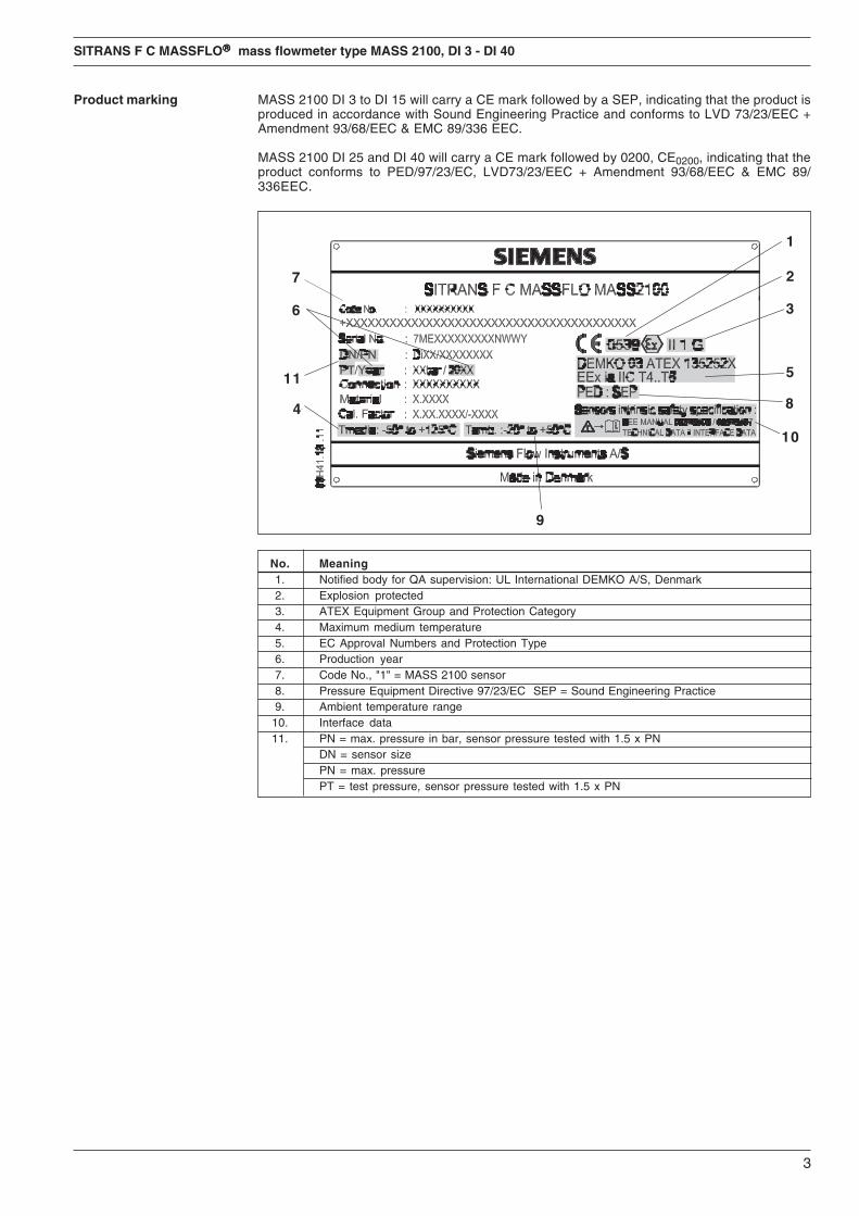
Product marking MASS 2100 DI 3 to DI 15 will carry a CE mark followed by a SEP, indicating that the product isproduced in accordance with Sound Engineering Practice and conforms to LVD 73/23/EEC +Amendment 93/68/EEC & EMC 89/336 EEC.
MASS 2100 DI 25 and DI 40 will carry a CE mark followed by 0200, CE0200, indicating that theproduct conforms to PED/97/23/EC, LVD73/23/EEC + Amendment 93/68/EEC & EMC 89/336EEC.
No. Meaning1. Notified body for QA supervision: UL International DEMKO A/S, Denmark2. Explosion protected3. ATEX Equipment Group and Protection Category4. Maximum medium temperature5. EC Approval Numbers and Protection Type6. Production year7. Code No., "1" = MASS 2100 sensor8. Pressure Equipment Directive 97/23/EC SEP = Sound Engineering Practice9. Ambient temperature range
10. Interface data11. PN = max. pressure in bar, sensor pressure tested with 1.5 x PN
DN = sensor sizePN = max. pressurePT = test pressure, sensor pressure tested with 1.5 x PN
7
11
9
10
8
6
4
1
2
3
5
4
SITRANS F C MASSFLO®®®®® mass flowmeter type MASS 2100, DI 3 - DI 40
Direction of flow Static back pressure Static back pressure
The arrow on the sensor indicates the direction of flow defined as “positive” (the meter is able tomeasure flow in both directions).As far as possible, the liquid should flow in the direction of the arrow (on the sensor) to avoid partialemptying of the sensor, especially with low flow.In addition there should be a valve (check/solenoid) that closes when the flow is zero so that theliquid does not flow back and causes partial emptying of the sensor.
Valve
ReverseInverseForward
Valve
Location The flowmeter can be located both indoors and outdoors, but the following conditions must beobserved:
Liquid temperature: −50 to +180°C.Ambient temperature, operation: −20 to +55°C.
When the temperature difference between a liquid and the surroundings is large, the sensor mustbe insulated to prevent 2-phase flow and the resulting measuring inaccuracy. This appliesespecially in the case of low flow.
Important!The sensor must always be completely filled with a homogeneous liquid in single phase,otherwise measuring errors will occur.
If there is air/gas in the liquid or liquids which are volatile, horizontal sensor mounting isrecommended.
Version Compact IP 67 Separate Compact Ex-d
Horizontal mounting inpipe
Mount the sensor on a vibration-free wall or steel frame as shown.Ensure that the sensor is not emptied of liquid (during normal operation) otherwise incorrectmeasurement will occur.
Locate the sensor low in the pipe system in order to avoid under-pressure in the sensor andconsequent air separation in the liquid.If the flowmeter is mounted horizontally, it is self-emptying.
With low flow, horizontal mounting is recommended, in this way air bubbles are easier toremove.
5
SITRANS F C MASSFLO®®®®® mass flowmeter type MASS 2100, DI 3 - DI 40
Vertical mounting in pipe
Locate the unit low in the pipe system in order to avoid under-pressure in the sensor and con-sequent air separation in the liquid.
Direction of flow Static back pressure
Valve
Direction of flow
As far as possible, the liquid should flow up-wards to make bubble removal easier.With vertical mounting, a check valve, whichcloses on zero flow, must always be installed sothat the liquid cannot flow back and partiallyempty the sensor.The arrow on the sensor indicates positive(forward) flow direction.
Valve 0-point adjustment
ValveValve
Direction of flow
Direction of flow
Direction of flow
Valve
Direction of flow
Valve
To facilitate 0-point adjustment, a valve with good shut-off should always be mounted in connectionwith the sensor.
• The sensor should be completely filled with liquid.• The valve must be closed.• Wait a few minutes to let the flow become zero.
Vibration
Locate the flowmeter as far away as possible from components that generate mechanical vibrationin the piping.Or ensure that there is no direct connection with them e.g. by using flexible connections.Altenatively, the flowmeter can be located after a bend.
6
SITRANS F C MASSFLO®®®®® mass flowmeter type MASS 2100, DI 3 - DI 40
For remote installation mount the adaptor ontop of the sensor interface, if not alreadymounted.When fitting the multiple plug, please make surethat it is correctly oriented (note the little tap).
Mounting of adapter
Mount the multiple plug in the adaptor andtighten the glands on the plug to obtain opti-mum sealing.Note the wire colours when connecting theMASS 6000. Refer to the diagram for electricalwiring.
Mounting of multiple plug
Electrical connection If the meter is supplied as IP 67 or Ex-d compact version, only the output must be threaded. Referto either the handbook or the manual. If the sensor is meant for separate mounting, it must beconnected as follows:
Mounting of pressurerelease valve
ImportantBefore demounting the nipple from the sensor enclosure, please note the following:Penetration of humidity, liquid or particles into the sensor must be avoided as it may influence themeasurement and in worst case damage the measuring function. This, however, can be avoidedwhen following the procedure below:
Cross-talk
If the flowmeters are located close to each other, e.g. in the same pipe section, the meters maydisturb each other in measurement, especially with low flow. Locate the meters with a flexibleconnection instead of a permanent connection.Avoid mounting the meter on the same steel frame. I.e. insulate the meters mechanically.
1. Place the sensor in a dry and clean place andleave it there to acclimate until it obtainsambient temperature, best at approx. 20 °C.
2. Be careful when demounting the nipple andmounting the pressure release valve.
3. Check that the pressure release valve hasbeen correctly mounted and thoroughlytightened so that the sealing ring fits tightly.Always replace old sealing rings by newones after each dismantling.
7
SITRANS F C MASSFLO®®®®® mass flowmeter type MASS 2100, DI 3 - DI 40
Wiring diagram
Mount the multiple plug in the sensor and connect the wire colours as shown in the diagram forMASS 6000
Dimensions and weight
8
SITRANS F C MASSFLO®®®®® mass flowmeter type MASS 2100, DI 3 - DI 40
L1 L2 L3 H1 B1 D1 D2 D3 D4 D5Type Pressure rating Size mm mm mm mm mm mm mm mm mm mm
DI 3 Pipe thread ISO 228/1 -PN 100 1/4" 400 280 75.0 60 0 21.3 104 - - -G 1/4
Pipe thread ANSI/ASMEPN 100 1/4" 400 280 75.0 60 0 21.3 104 - - -B 1.20.1 - 1/4" NPT
DI 6 Flange DIN 2635 PN 40 DN 10 560 390 62.0 40 12 17.0 104 90.0 60.0 14.0Flange ANSI B 16.5 CLASS 150 1/2" 624 390 62.0 40 12 17.0 104 88.9 60.5 15.7Flange ANSI B 16.5 CLASS 600 1/2" 608 390 62.0 40 12 17.0 104 95.3 66.5 15.7Screwed connection DIN 11851 PN 40 DN 10 532 390 62.0 40 12 17.0 104 - - -Clamp ISO 2852 PN 16 25 mm 570 390 62.0 40 12 17.0 104 - - -
DI 15 Flange DIN 2635 PN 40 DN 15 620 444 75.0 44 20 21.3 129 95.0 65.0 14.0Flange ANSI B 16.5 CLASS 150 1/2" 639 444 75.0 44 20 21.3 129 88.9 60.5 15.7Flange ANSI B 16.5 CLASS 600 1/2" 660 444 75.0 44 20 21.3 129 95.3 66.5 15.7Screwed connection DIN 11851 PN 40 DN 15 586 444 75.0 44 20 21.3 129 - - -Clamp ISO 2852 PN 16 25 mm 624 444 75.0 44 20 21.3 129 - - -
DI 25 Flange DIN 2635 PN 40 DN 25 934 700 74.5 126 25 33.7 219 115.0 85.0 14.0Flange ANSI B 16.5 CLASS 150 1" 967 700 74.5 126 25 33.7 219 108.0 79.2 15.7Flange ANSI B 16.5 CLASS 600 1" 992 700 74.5 126 25 33.7 219 124.0 88.9 19.1Screwed connection DIN 11851 PN 40 DN 32 922 700 74.5 126 25 33.7 219 - - -Clamp ISO 2852 PN 16 38 mm 940 700 74.5 126 25 33.7 219 - - -
DI 40 Flange DIN 2635 PN 40 DN 40 1064 850 71.5 180 0 48.3 273 150.0 110.0 18.0Flange ANSI B 16.5 CLASS 150 11/2" 1100 850 71.5 180 0 48.3 273 127.0 98.6 15.7Flange ANSI B 16.5 CLASS 600 11/2" 1128 850 71.5 180 0 48.3 273 155.4 114.3 22.4Screwed connection DIN 11851 PN 25 DN 50 1090 850 71.5 180 0 48.3 273 - - -Clamp ISO 2852 PN 16 51 mm 1062 850 71.5 180 0 48.3 273 - - -
Sensorsize
Connections
L5 L3 H3 B2 D6 D7 D8Flange Pressure rating Size mm mm mm mm mm mm mm
DI 3 DIN 2635 PN 40 DN 15 234 75.0 122.0 22.0 95.0 65.0 14.0ANSI B16.5 CLASS 150 1/2" 234 75.0 131.6 22.0 88.9 60.5 15.7
DI 6 DIN 2635 PN 40 DN 15 234 62.0 112.0 22.7 95.0 65.0 14.0ANSI B16.5 CLASS 150 1/2" 234 62.0 121.6 22.7 88.9 60.5 15.7
DI 15 DIN 2635 PN 40 DN 15 234 75.0 126.5 31.5 95.0 65.0 14.0ANSI B16.5 CLASS 150 1/2" 234 75.0 136.1 31.5 88.9 60.5 15.7
DI 25 DIN 2635 PN 40 DN 15 420 74.5 213.6 60 95.0 65.0 14.0ANSI B16.5 CLASS 150 1/2" 420 74.5 223.2 60 88.9 60.5 15.7
DI 40 DIN 2635 PN 40 DN 15 500 71.5 267.5 43 95.0 65.0 14.0ANSI B16.5 CLASS 150 1/2" 500 71.5 277.1 43 88.9 60.5 15.7
Sensor MASS 2100 with "heating jacket"
Sensorsize
ConnectionsHeated
We have checked the contents of this manual for agreement with the hardware andsoftware described. Since deviations cannot be precluded entirely, we cannot guaranteefull agreement. However, the data in this manual are reviewed regularly and anynecessary corrections included in subsequent editions. Suggestions for improvementare always welcomed.
Technical data subject to change without prior notice.
The reproduction, transmission or use of this document or its contents is not permitted withoutexpress written authority.Offenders will be liable for damages. All rights, including rights created by patent grant orregistration of a utility model or design, are reserved.
Copyright © Siemens AG 05.2005 All Rights Reserved
Siemens Flow Instruments A/SNordborgvej 81DK-6430 Nordborg
Order no.: FDK-521H0999-02Printed in: Denmark
北京迪妙声科技有限公司 BEJING DELLSONICS SCIENCE & TECHNOLOGY LTD.
地址:北京海淀区魏公村街 1号韦伯豪家园 3-3-702 (100081) http://www.dellsonics.com
DELLSONICS
公 司 简 介
北京迪妙声科技有限公司(原名北京妙声力科技有限公司),位于北京市海淀区中关村
南大街,是与西门子公司德国总部正式签约的西门子过程仪表及分析仪器核心合作伙伴,
也是西门子北方区域规模最大、实力最强的优秀代理商。
公司主营:
一、西门子-妙声力(Milltronics)系列物位产品:超声波物位计、超声波液位差计、超声波泥水界
面计、超声波明渠流量计、雷达物位计、射频导纳物位计、射频导纳油水界面计、;射频导纳物位开关、
音叉式物位开关、阻旋式物位开关;皮带称、固体质量流量计、冲板流量计等。
二、西门子过程仪表产品:电磁流量计、质量流量计、超声波流量计、 温度变送器、压力变送器、
阀门定位器、气体分析仪等。
三、德国 UWT 公司的阻旋式料位开关、音叉式料位开关、重锤式料位计等产品。
四、自行研发生产超声波液位计、温度变送器、压力变送器、数显表及油田专用仪器等产品。
成立于 1954 年的西门子-妙声力公司(Milltronics)是世界公认的超声波物位测量领域
的领导者,全球最大的超声波物位仪表生产厂家,在超声波、雷达、电容技术领域拥有超过 60
项专利,超声波产品的综合性能指标经美国《控制》杂志评比,其综合性能名列全球第一!
作为西门子公司长期稳定的代理商,我公司有着 10 余年产品的销售和服务经验,无论
从专业技术水平、现货及备件库存量、售后服务质量、仪表维护以及故障产品国内维修能力
等方面,都具备显著的优势。尤其是我公司一流的技术支持和高效率高品质的服务体系,在
业界具有很高的知名度。
如果您需要相关的产品,需要咨询技术问题,需要值得信赖的合作伙伴,敬请来电垂询!
商务部总机电话:010-88579530/31/32/33,88579597,88571841,81968099(小灵通)
传真:总机转 50
谢谢您的合作与支持!
电话:010-88579530/31/32/33,88579597,88571841 传真:总机转 50 E-mail:[email protected]