s a m s o n - 56
TRANSCRIPT

............................................................................................................................................................
SMALL AGRICULTURAL AND GARDEN
MACHINES AND EQUIPMENT
............................................................................................................................................................
D I S K G R A S S C U T T E R
S A M S O N - 56
For mowing high grass of all kinds of grass-plots

2
The product design corresponds to the requirements of Act No. 22/1997 Collection
and connected acts and regulations.
The manufacturer reserves the right to carry out technical modifications and
innovations in the course of manufacture which can not be described in these
directions and which do not substantially influence the function and safety of
operation. The manufacturer reserves the right without prior notice or obligation to
carry out technical modifications and innovations which may not correspond with the
text and diagrams of these directions.
text and illustrations c 1999 * Mepol Libice a.s.*
publication No: ML – 029BK - 98
We ask you to take note of the following information concerning your machine. It is
necessary that this information be known when ordering spare parts.
We recommend that you make a copy of this completed page on purchase of the
machine in case of loss or theft of the original.
Model SAMSON - 56 BK
Serial number
Purchase date
Supplier
Address
Telephone / fax
Comments:

3
W A R N I N G!
The user is obliged to acquaint himself with these directions and observe all operating
instructions in order to avoid endangering the health and property of the user and other
persons. The safety instructions in these operating instructions do not describe all
possibilities, conditions and situations which can occur in practice.
It is assumed that each person handling this machine or carrying out maintenance on
this machine exercises common sense, caution, prudence, care, and conscientiousness.
Only mentally and physically healthy persons should be allowed to operate this
machine.
In cases of professional use of this machine the owner is obliged to instruct persons
operating the machine on safety of operation and safety of work, and to carry out
training and keep records of training.
The manufacturer is not responsible for damage caused by unauthorised use,
incorrect operation of the machine, or for damages resulting from any
modification of the machine without the manufacturer's consent.
In the event that any information in the operating instructions is incomprehensible
please contact your dealer or the manufacturer directly.
Address and telephone contacts are provided at the end of these operating instructions.
The operating instructions included with the machine form an integral part of the
product. The operating instructions must be available at all times, and must be kept in
an accessible place where no danger of destruction exists. When selling the machine to
another person the operating instructions of the machine must be handed over to the
new owner. The manufacturer has no responsibility for risks, danger, accidents and
injuries resulting from the operation of the machine unless the above conditions are
fulfilled.
When operating the machine it is necessary to follow safety regulations in order to
avoid the risk of injury, not only of the person operating the machine, but also other
persons in the surroundings. These instructions are indicated in the operating
instructions by this safety symbol:
When you see this symbol read the
following communication carefull

4
C O N T E N T S
I. INTRODUCTION........................................................................................................5
II. TECHNICAL DESCRIPTION ...................................................................................6
III. TECHNICAL DATA ..................................................................................................7
IV. SAFETY REGULATIONS.......................................................................................10
V. OPERATING INSTRUCTIONS ..............................................................................13
VI. MAINTENANCE AND ATTENDANCE ...............................................................21
VII. STORAGE..................................................................................................................22
VIII. LIQUIDATION OF PACKAGES............................................................................22

5
I. INTRODUCTION
Dear customer!
By purchasing this product you have become the owner of one product in a wide range
of small agricultural and garden machines and tools manufactured under the following
brand
............................................................................................................................................................ SMALL AGRICULTURAL AND GARDEN
MACHINES AND EQUIPMENT ............................................................................................................................................................
by the joint-stock company MEPOL LIBICE nad CIDLINOU.
This system has been designed for allotment holders, small growers and farmers and
peasants running small farms and areas.
It is possible without any difficulties to use the machines, equipment and tools of this
system for all necessary works: for example, both active and passive soil tilling,
pumping liquids, mowing blade plants and grass, snow removal, sweeping away
wastes and dirt, and also transport of any material on uniaxial trailers.
Please read these operating instructions carefully. If these operating instructions are
followed, our products will serve you reliably for many years.
6
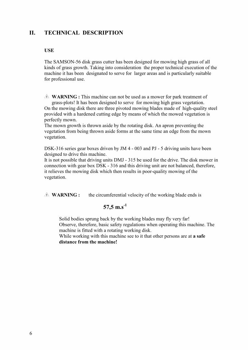
II. TECHNICAL DESCRIPTION
USE
The SAMSON-56 disk grass cutter has been designed for mowing high grass of all
kinds of grass growth. Taking into consideration the proper technical execution of the
machine it has been designated to serve for larger areas and is particularly suitable
for professional use.
WARNING : This machine can not be used as a mower for park treatment of
grass-plots! It has been designed to serve for mowing high grass vegetation.
On the mowing disk there are three pivoted mowing blades made of high-quality steel
provided with a hardened cutting edge by means of which the mowed vegetation is
perfectly mown.
The mown growth is thrown aside by the rotating disk. An apron preventing the
vegetation from being thrown aside forms at the same time an edge from the mown
vegetation.
DSK-316 series gear boxes driven by JM 4 - 003 and PJ - 5 driving units have been
designed to drive this machine.
It is not possible that driving units DMJ - 315 be used for the drive. The disk mower in
connection with gear box DSK - 316 and this driving unit are not balanced, therefore,
it relieves the mowing disk which then results in poor-quality mowing of the
vegetation.
WARNING : the circumferential velocity of the working blade ends is
57,5 m.s-1
Solid bodies sprung back by the working blades may fly very far!
Observe, therefore, basic safety regulations when operating this machine. The
machine is fitted with a rotating working disk.
While working with this machine see to it that other persons are at a safe
distance from the machine!

7
III. TECHNICAL DATA
SAMSON - 56
unit value
Length mm 770
Height mm 516
Width mm 288
Mass kg 44
Maximum attack width of the machine cm 56
Working blade speed
when using gear boxes 2T min-1
1706 ± 50
when using gear boxes 4T min-1
1963 ± 50
Circumferential velocity of blades
when using gear boxes 2T m.s-1
50 ± 1.46
when using gear boxes 4T m.s-1
57.5 ± 1.46
Blade drive gear speed ratio - 1.2
Machine surface capacity
(according to vegetation) m3/hour 800 - 1400
Oil filling capacity l 0.15
Oil quality according to API GL - 4, GL - 5
according to SAE 90, 80 W - 90

8
TECHNICAL DESCRIPTION :
Drive: the drive is a supporting component of the whole machine. The drive body is a
grey cast iron casting with machined function surfaces. The case cover is fitted on the
body with four screws. The drive shaft is mounted on antifriction bearings in the drive
body. A bevel gear wheel is mounted on the front end. On the bottom end of the bevel
pinion which is mounted in the case cover on two ball bearings and one needle bearing
there is a rotating disk provided with three mowing blades which is carried along by
means of a feather. The bottom disk is pivoted on ball bearings.
The mowing blades are pivoted on the circumference of the rotating disk. The screws
of the rotating disks are made of high-quality high-strength steel .
Oil is filled through an oil filling hole fitted with a plug.
Cover: the drive is fitted with a cover made of ABS plastic. The cover ensures the
discharge of mown vegetation out of the machine. Rubber aprons are screwed on to
the rear part of the cover, as well as a handrail for handling the machine and a rubber
apron preventing mown vegetation from flying off between the power assist wheels.
The side apron is fitted to a holder which is fitted in a rectangular tube located on the
rear part of the machine cover and it is secured by means of two screws.
A cast iron weight with a mass of 6 kg is screwed on the cover to ensure a better
balance which is necessary for a better copying terrain by the rotating disk of the
machine, particularly in cases of a markedly uneven terrain.
9
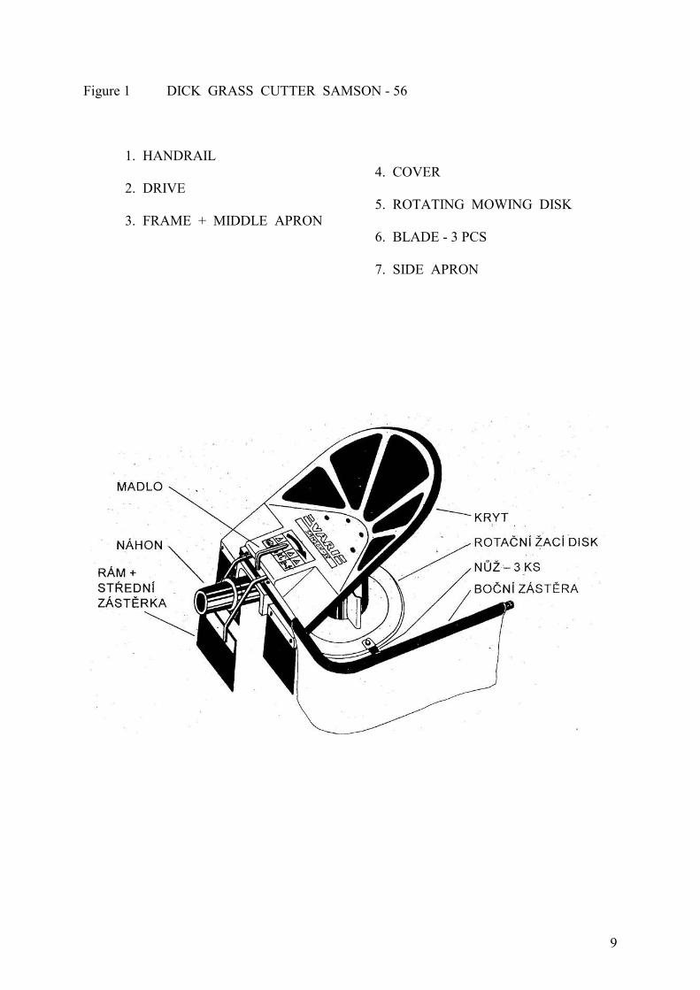
Figure 1 DICK GRASS CUTTER SAMSON - 56
1. HANDRAIL
4. COVER
2. DRIVE
5. ROTATING MOWING DISK
3. FRAME + MIDDLE APRON
6. BLADE - 3 PCS
7. SIDE APRON

10
IV. SAFETY REGULATIONS
This international safety symbol indicates important information concerning safety. When
you see this symbol pay attention for the possibility of your own injury or injury of other
persons, and read the following communication carefully.
1. Follow the basic safety instructions when operating this machine. The machine is fitted
with a rotating working blade. The maximum circumferential velocity is 57.5 m.s-1.
Therefore, see to it that other persons keep a safe distance from the machine during
operation.
Before using the machine all foreign bodies (as stones, wires etc.) which could be hurled
away or could result in damage to the machine should be removed from the vegetation.
Avoid mowing in places where it is not possible to remove such bodies.
Before each use check the machine for damaged or loosened parts. All defects found must
be removed immediately. Repair with original manufacturer's parts only.
2. When working wear close-fitting work clothing, hard-wearing work boots, work gloves,
and protect your eyes with goggles. Observe the safe distance given by the grip of the
machine.
3. All persons operating the machine must be more than eighteen years old and an owner
of a class A, B or T driving licence. All persons operating the machine are obliged to
familiarise themselves with these operating instructions and to be acquainted with general
principles of work safety.
4. Do not start the engine in closed rooms! After the engine has been stopped the exhaust
silencer of the engine remains hot, therefore, pay increased attention to handling the
machine. Pay attention to refuelling to avoid leakage or spillage of fuel and staining parts
of the engine.
Before starting wipe stained parts dry or wait until the fuel is evaporated.
5. When working with the machine all other persons and animals must be out of the
working area of the machine. Anyone operating the machine must not continue working
unless other persons are kept at a safe distance.
6. It is not allowed to remove any protecting devices and protecting covers from the
machine!
7. The machine shall be transported either by an automobile or by a set of an uniaxial
small tractors with a semi-trailer.
8. When working with a driving unit, gear box and disk mower transport is not allowed on
any roads with the exception of a perpendicular crossing of these roads.

11
9. The safe slope capability of the machine is 7 grades.
10. The machine should not be used at night from 21.00 to 7.00 in recreation or health
zones.
11. Before working with the machine verify the function of the breaks located on the left-
hand handlebar of the driving unit. This breaker switches off the engine ignition, therefore,
stopping the engine immediately after the working place has been left by an operator either
under a critical emergency condition or at shutting the machine down.
The safety ignition breaker has three positions (see Figure 2a).
Position 1 is used when starting the engine.
Stand by the right-hand handlebar when starting the engine. Operate the accelerator lever
with your left hand, start the engine with your right hand with the starting cord. When
starting the engine stand so as to maintain a safe distance from the rotating mowing disk
which is given by the axis of the gearbox power assist wheels.
With the safety ignition breaker in position 1 always put the gear in neutral or disengage
the clutch of the power assist wheels!
Position 2 is used for operation of the machine. During operation of the machine when an
operator holds the guiding grips by both hands the wire catch must always be released!
Position 3. If an operator releases the handlebar in a critical situation the engine ignition is
short circuited, therefore, the engine is stopped. It is sufficient to let go of the left-hand
handlebar hand rail and the engine stops. This position is used also for stopping the engine
at shut down.
12. Do not drive across readily flammable materials - for example hay or straw.
13. All repairs, adjustments, settings, lubrication and cleaning of the machine should be
carried out in the standstill position at the same time with the spark plug cable or driving
unit disconnected.
Figure 2 SAFETY IGNITION BREAKER POSITIONS BVA - 96
12
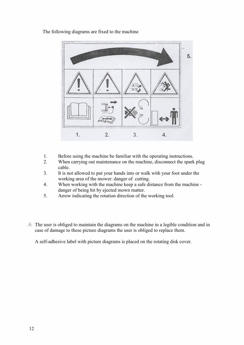
The following diagrams are fixed to the machine
1. Before using the machine be familiar with the operating instructions.
2. When carrying out maintenance on the machine, disconnect the spark plug
cable.
3. It is not allowed to put your hands into or walk with your foot under the
working area of the mower: danger of cutting.
4. When working with the machine keep a safe distance from the machine -
danger of being hit by ejected mown matter.
5. Arrow indicating the rotation direction of the working tool.
The user is obliged to maintain the diagrams on the machine in a legible condition and in
case of damage to these picture diagrams the user is obliged to replace them.
A self-adhesive label with picture diagrams is placed on the rotating disk cover.

13
V. OPERATING INSTRUCTIONS
MACHINE ASSEMBLY
At first, get the driving unit and gear box ready in accordance with the appropriate
operating instructions.
Apply a thin layer of plastic lubricant (e.g. MOGUL A 00) on the surface of the drive
body, shift out (movement 1 / Figure 3) an arresting pin on the gear box flange and
slide the drive body in this flange up to the stop (movement 2 / Figure 3).
Unlock (movement 3 / Figure 3) a locking pin on the gear box flange so as to fit in an
oval hole in the drive body.
When handling the machine hold the machine by the following two points:
in the rear part of the machine using the handrail, in the front part using the drive
cover border. The machine must be handled by two operators.
After sliding into the drive move with the machine from side to side in the direction of
the machine's longitudinal axis until the pin fits in the hole. The pin on the arresting
pin must fit in the bottom notch. During this manipulation hold the machine using the
cover border on the sides, approximately in the middle of its length.
Slide the apron in the holder in the rear part into such a position as to ensure a gap of
25 centimetres between the apron and the shifted out blade in normal position to the
machine axis. Secure the apron holder in this position by tightening two screws M6.
The side plate of the guiding handles of the driving unit should be adjusted in a
position as close as possible to the engine to ensure a shifting of the centre of gravity
of the driving unit and gear box in a forward direction and pushing the rotating disk
with blades against ground.
Before starting proper work with the machine check the function of the safety ignition
breaker BVA-96!

14
Figure 3 FITTING THE MACHINE DRIVE ON THE GEAR BOX
USE OF THE MOWER
Before working with the machine make sure that on places where you intend to use the
mower there are no foreign bodies hidden in the vegetation (stones, wires, tubes, thick
branches etc.) which should be removed because they could be hurled away or could
result in damage to the machine. Avoid mowing in areas where it is not possible to
clear such bodies.
A person operating the mower is obliged to keep all other unauthorised persons and
animals at a safe distance.
Check that the mowing blades are undamaged and secure in the disk.
If all parts of the machine (driving unit, gear box and disk mower) are adjusted in
accordance with the operating instructions you can start proper working.

15
Power assisting with mower
1. When starting the engine it is unconditionally necessary to disengage and secure the
clutch lever by means of which the clutch of the power assist wheels is disengaged
(see Figure 4).
In gear boxes provided with drive which can be disengaged, disengage the drive by
means of a pull-rod.
2. Start the engine. At the same time follow the operating instructions for the driving
unit.
Stand by the right-hand handlebar grip when starting the engine. Operate the
accelerator lever with your left hand, start the engine with the use of the starting cord
with your right hand. When starting the engine stand so as to maintain a safe distance
from the rotating mowing disk which is given by the axis of the gearbox power assist
wheels.
3. Grasp the handlebars, then depress the power assist clutch lever and put arrest of the
clutch lever out of operation.
Increase the engine speed by using the accelerator lever.
Disengage the lever. Now, the power assist wheels are connected with the drive. The
machine is put in motion. Work always with maximum engine speed.
4. If you wish to stop, first decrease the engine speed.
Never disengage the clutch lever at high engine speeds - at which the engine has
maximum capacity and torque. The design of the clutch for engaging wheel power
assist enables the clutch to be disengaged only at lower engine speeds - when the
centrifugal clutch does not transmit a high power output and torque to the gear box.
Repeated moving off should be carried out in accordance with paragraph 3.
At the machine shut down set the accelerator lever in the position of non-load speed
and let the clutch lever disengaged. In this way, the machine is secured against
spontaneous movement.
Warning: During mowing it is necessary to pay attention to the fact that the bottom disk is
continuously pressed down against the ground and does not rebound. The rebounding
of the disk results in a sloppy mowing of the vegetation and uneven stubble field.
In particular, it is necessary to take care of pressing down the disk when mowing in an
uneven terrain!
16
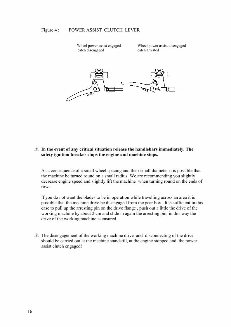
Figure 4 : POWER ASSIST CLUTCH LEVER
Wheel power assist engaged Wheel power assist disengaged
catch disengaged catch arrested
In the event of any critical situation release the handlebars immediately. The
safety ignition breaker stops the engine and machine stops.
As a consequence of a small wheel spacing and their small diameter it is possible that
the machine be turned round on a small radius. We are recommending you slightly
decrease engine speed and slightly lift the machine when turning round on the ends of
rows.
If you do not want the blades to be in operation while travelling across an area it is
possible that the machine drive be disengaged from the gear box. It is sufficient in this
case to pull up the arresting pin on the drive flange , push out a little the drive of the
working machine by about 2 cm and slide in again the arresting pin, in this way the
drive of the working machine is ensured.
The disengagement of the working machine drive and disconnecting of the drive
should be carried out at the machine standstill, at the engine stopped and the power
assist clutch engaged!
17
Working attack of the machine:
After the above mentioned elemental operations have been carried out it is possible to
start the proper working with the machine.
Set up the engine maximum speed, put the rotation disk in the rotation with maximum
speed and then set the machine in motion against the vegetation you wish to mow.
The vegetation mown is thrown away by the rotating disk in the direction against the
apron by means of which it is put in a row. If the vegetation mown is very dense,
overgrown, bad, rotten from the bottom or flattened it is necessary proportionally to
this condition to decrease the width of the machine attack so as to avoid a marked
decrease of the engine speed and clutch slip ( slipping clutch is whistling or rattling).
If a congestion of the space between the rotating disk and the power assist unit occurs
stop the motion, stop the engine and clean this space.
Pay an increased attention and take increased care when cleaning the space below the
cover. The cutting edges of the working blades are sharp. When cleaning protect your
hands with protective gloves.
CONTROL TECHNIQUE OF THE SAFETY IGNITION
BREAKER
The safety ignition breaker BVA - 96 corresponds to the standard of commonly used
safety ignition breakers used by manufacturers of small agricultural mechanisation
abroad.
18
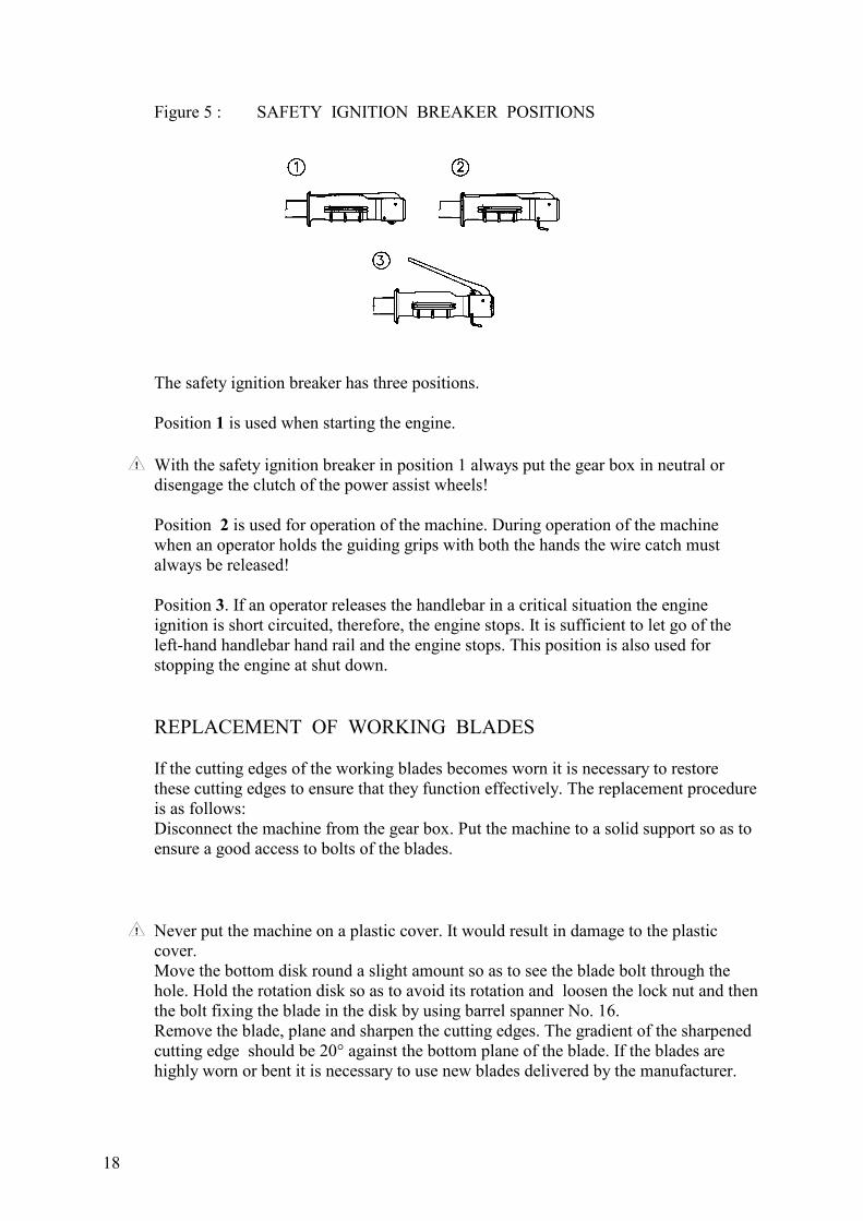
Figure 5 : SAFETY IGNITION BREAKER POSITIONS
The safety ignition breaker has three positions.
Position 1 is used when starting the engine.
With the safety ignition breaker in position 1 always put the gear box in neutral or
disengage the clutch of the power assist wheels!
Position 2 is used for operation of the machine. During operation of the machine
when an operator holds the guiding grips with both the hands the wire catch must
always be released!
Position 3. If an operator releases the handlebar in a critical situation the engine
ignition is short circuited, therefore, the engine stops. It is sufficient to let go of the
left-hand handlebar hand rail and the engine stops. This position is also used for
stopping the engine at shut down.
REPLACEMENT OF WORKING BLADES
If the cutting edges of the working blades becomes worn it is necessary to restore
these cutting edges to ensure that they function effectively. The replacement procedure
is as follows:
Disconnect the machine from the gear box. Put the machine to a solid support so as to
ensure a good access to bolts of the blades.
Never put the machine on a plastic cover. It would result in damage to the plastic
cover.
Move the bottom disk round a slight amount so as to see the blade bolt through the
hole. Hold the rotation disk so as to avoid its rotation and loosen the lock nut and then
the bolt fixing the blade in the disk by using barrel spanner No. 16.
Remove the blade, plane and sharpen the cutting edges. The gradient of the sharpened
cutting edge should be 20° against the bottom plane of the blade. If the blades are
highly worn or bent it is necessary to use new blades delivered by the manufacturer.

19
Fit the screw, blade, and flat washer back on. Tighten the screw so as to ensure that a
clearance of the blade on the bolt in vertical direction is of 0.5 to 1 mm and that the
blade is free rotating on the bolt. Then screw on the nut. Using the barrel spanner No.
16 hold the bolt head and tighten the nut firmly. Make sure that all blades are free
rotating on the bolts. The cutting edge of the blades is double-sided. After one side has
been worn it is possible that the blade be rotated and the cutting edge of the other side
of the blade be utilised. We recommend you replace the blade at the same time with
replacement of the bolt.
Take care while dismantling the blades. The cutting edges of the blades are sharp.
Protect your hands with protective gloves.

20
Note:
After any non-professional repair of the blades without using original spare parts the
manufacturer is not responsible for damage caused by the machine.
The blade is marked as FRANCOUZ R 85/2. This designation indicates the
manufacturer and certification mark.
Figure 6 : Blade replacement

21
VI. MAINTENANCE AND ATTENDANCE
To ensure as high as possible satisfaction with our products for a long time it is
necessary that appropriate care be taken of maintenance and attendance of this
machine and all auxiliary equipment.
By carrying out regular maintenance on this mower machine wear is avoided and the
correct functioning of all parts of the machine is ensured. Follow all instructions
relating to time intervals of maintenance and adjustment of the machine.
We recommend you keep records on the number of working hours of the machine and
on conditions under which the machine has been in operation.
Follow, therefore, the following instructions:
1. Gears of the gear boxes are in operation in an oil bath.
The oil should be exchanged in new machines after the first 10 hours of
operation and then after 100 running hours or after the end of the season. In
this way an excessive wear of the gearing is avoided. The oil should be
checked once a month. The minimum classification of the gear oil should be
according to API GL - 4, GL - 5, according to SAE 90 or 80W - 90.
As for domestic oils the transmission oil MOGUL TRANS 90 or MOGUL
TRANS 80W - 90 are fully satisfactory.
In case of oils with a higher classification (API GL - 5, SAE 80 W - 90) it is
possible that the exchange interval be prolonged up to 130 hours ( it is
necessary to maintain a time period of 10 hours for running-in.)
The oil exchange should be carried out while the drive case is warm because
the oil is drained more easily. Loosen the plug fitted on the case cover and
drain the oil into a vessel prepared before. Fill up the drive case with new oil.
The oil level should reach the bottom edge of the hole. Then screw the plug in
again. If the gasket below the plug is damaged it should be replaced with a new
one.
When replacing oil basic hygiene rules should be followed and regulations and laws
on environmental protection should be observed.
2. Check bolted joints for tightness. Before any use of the mower check bolts fastening
the working blades for tightness.

22
3. Care should be taken of cleanness of all bearing and connecting surfaces. Apply a
thin layer of plastic lubricant MOGUL A 00 on a flange for connecting the drive with
the gear box.
4. After the end of the season remove all dirt and plant residue.
Check that the working blades are in an undamaged condition, sharpen cutting edges
of blades and apply a conservation oil.
5. When cleaning, washing the machine with water, solvents and other chemical
agents, it is necessary to proceed in such a way to follow accepted provisions and
regulations on the protection of rivers and streams and other water sources against
pollution, contamination and contamination by chemical substances.
VII. STORAGE
Store the machine in dry places. The access of unauthorised persons to the machine
should be avoided.
In case of a longer shut down of the machine, conserve all connecting surfaces with
the use of a conservation oil.
Protect the machine against the effects of weather.
VIII. LIQUIDATION OF PACKAGES
Paper packages - sale to purchase of secondary materials
deposition on collection places in containers
incineration
other utilising
Plastic packages - deposition on collection places in containers
Wood - liquidation by incinerating, crushing or chipping