rx9500 bulk descrambler - mediasolutions.ericsson.com · preliminary pages en/lzt 790 0049/1 r4a...
TRANSCRIPT

RX9500 Bulk Descrambler Software Version 1.2.0 (and later)
REFERENCE GUIDE
EN/LZT 790 0049/1 R4A

RX9500 Bulk Descrambler
ii EN/LZT 790 0049/1 R4A
Copyright
© Copyright Ericsson AB 2017. All rights reserved. No part of this document may be reproduced in any form without the written permission of the copyright owner.
Disclaimer
No part of this document may be reproduced in any form without the written permission of the copyright owner.
The contents of this document are subject to revision without notice due to continued progress in methodology, design and manufacturing. Ericsson shall have no liability for any error or damage of any kind resulting from the use of this document.
SVENSKA - LÄS DETTA FÖRST! Om Ni inte förstår informationen i denna handbok. ARBETA DÅ INTE MED DENNA UTRUSTNING. En översättning till detta språk av denna handbok
kan också anskaffas, på Er bekostnad.
ENGLISH (UK) - READ THIS FIRST! If you do not understand the contents of this manual. DO NOT OPERATE THIS EQUIPMENT. Also, translation into any EC official language of this
manual can be made available, at your cost.
ΕΛΛΗΝΙΚΑ - ΔΙΑΒΑΣΤΕ ΠΡΩΤΑ ΑΥΤΟ! Αν δεν καταλάβετε το περιεχόμενο αυτού του βοηθήματος/εγχειριδίου. ΜΗΝ ΛΕΙΤΟΥΡΓΗΣΕΤΕ ΑΥΤΟΝ ΤΟΝ ΕΞΟΠΛΙΣΜΟ. Επίσης, αυτό το εγχειρίδιο
είναι διαθέσιμο σε μετάφραση σε αυτή τη γλώσσα και μπορείτε να το αγοράσετε.
DEUTSCH - LESEN SIE ZUERST DIESEN HINWEIS! Sollte Ihnen der Inhalf dieses Handbuches nicht klar verständlich sein, dann. BEDIENEN SIE DIESE GERÄTE NICHT! Eine Übersetzung des
Handbuches in diese Sprache ist gegen Berechnung lieferbar.
ESPAÑOL - LEA ESTE AVISO PRIMERO! Si no entiende el contenido de este manual. NO OPERE ESTE EQUIPO.
Podemos asimismo suministrarle una traducción de este manual al (idioma) previo pago de una cantidad adicional que deberá abonar usted mismo.
FRANÇAIS - AVANT TOUT, LISEZ CE QUI SUIT! Si vous ne comprenez pas les instructions contenues dans ce manuel. NE FAITES PAS FONCTIONNER CET APPAREIL. En outre, nous pouvons
vous proposer, à vos frais, une version française de ce manuel.
ITALIANO - LEGGERE QUESTO AVVISO PER PRIMO! Se non si capisce il contenuto del presente manuale. NON UTILIZZARE
L’APPARECCHIATURA.. È anche disponibile la versione italiana di questo manuale, ma il costo è a carico dell’utente.
PORTUGUÊS - LEIA O TEXTO ABAIXO ANTES DE MAIS NADA! Se não compreende o texto deste manual. NÃO UTILIZE O
EQUIPAMENTO. O utilizador poderá também obter uma tradução do manual para o português à própria custa.
NEDERLANDS - LEES DIT EERST! Als u de inhoud van deze handleiding niet begrijpt. STEL DEZE
APPARATUUR DAN NIET IN WERKING. U kunt tevens, op eigen kosten, een vertaling van deze handleiding krijgen.
DANSK - LÆS DETTE FØRST! Udstyret må ikke betjenes. MEDMINDRE DE TIL FULDE FORSTÅR
INDHOLDET AF DENNE HÅNDBOG. Vi kan også for Deres regning levere en dansk oversættelse af denne håndbog.
SUOMI - LUE ENNEN KÄYTTÖÄ! Jos et ymmärrä käsikirjan sisältöä. ÄLÄ KÄYTÄ LAITETTA. Käsikirja
voidaan myös suomentaa asiakkaan kustannuksella.
Contents
EN/LZT 790 0049/1 R4A iii
Contents Chapter 1: Introduction This chapter identifies the equipment versions covered by this Reference Guide, describes the purpose of the equipment in a typical system and lists the available options.
Chapter 2: Installing the Equipment This chapter provides product specific installation information including rack mounting, ventilation and pin-out details of the external connectors.
Chapter 3: Getting Started This chapter provides a guide to powering up the unit, setting up the IP address and using the unit.
Chapter 4: Front Panel Control This chapter describes the front panel display menus and options and details any operating procedures.
Chapter 5: Web GUI Control This chapter describes the configuration of the unit using the Web Graphical User Interface.
Chapter 6: Bulk Descrambling and Networking This chapter describes the principles and techniques used in the design of the equipment to aid in understanding its operation and function.
Chapter 7: Options, Licensing and Upgrades This chapter provides details of option cards that may be fitted to this equipment.
Chapter 8: Preventive Maintenance and Fault-finding This chapter details routine maintenance tasks, servicing advice and information regarding warranty and maintenance. It also lists error and error messages that may occur and recommends the action to be taken.
Annex A: Glossary
Annex B: Technical Specification

Preliminary Pages
iv EN/LZT 790 0049/1 R4A
Introduction In a fast changing, highly competitive market, media organizations need encoding solutions that deliver high quality, high reliability and operational flexibility. The number of channels continues to increase. HD is growing fast, offering a better quality viewing experience. Consumers are buying larger and larger TV sets and now plans are being laid for Ultra High Definition TV. All that means media organizations need to make the most efficient use of bandwidth and ensure consumers get a quality viewing experience.
The RX9500 Bulk Descrambler is designed for flexibility, modularity, and multiple independent outputs. Please ensure that you are familiar with the operation of the unit by reading this guide carefully.
This Reference Guide should be kept in a safe place for reference for the life of the equipment. It is not intended that this Reference Guide will be amended by the issue of individual pages. Any revision will be by a complete reissue. Further copies of this Reference Guide can be ordered from the address listed in Customer Services. If passing the equipment to a third party, also pass the relevant documentation.
Revision History Issues of this Reference Guide are listed below:
Issue Date Software Version Comments
A Feb 2014 1.0.0 Initial Release for the Bulk Descrambler (RX9500) Reference Guide SV 1.0.0
B Sep 2014 1.0.3 Updates for Software Version 1.0.3
C Jun 2016 1.1.0 Updates for Software Version 1.1.0
D Feb 2017 1.2.0 Updates for Software Version 1.2.0
Associated Documents The following manuals/guides are also associated with this equipment:
Ericsson Document Identity Title
2/1424-EN/LZT 790 0055 RX9500 Bulk Descrambler - Product Information - Quick Guide
1424-EN/LZT 790 0030 Installation, Safety and Compliance Information Generic Product Information - Reference Guide

Preliminary Pages
EN/LZT 790 0049/1 R4A v
Useful Links:
Installation, Safety and Compliance Information – Generic Product Information - Reference Guide can be viewed at: http://archive.ericsson.net/service/internet/picov/get?DocNo=17402-FGB101348&Lang=EN&HighestFree=Y
Product Guide downloads are available for all Product Families: http://www.ericsson.com/ourportfolio/products/television-and-video
Trademarks All best endeavors have been made to acknowledge registered trademarks and trademarks used throughout this Reference Guide. Any notified omissions will be rectified in the next issue of this Reference Guide. Some trademarks may be registered in some jurisdictions but not in others.
Registered trademarks and trademarks used are acknowledged below and marked with their respective symbols. However, they are not marked within the text of this Reference Guide.
Registered Trademarks
Dolby® Registered trademark of Dolby Laboratories Licensing Corporation.
DTS® Registered trademark of Digital Theater Systems Inc.
Ethernet® Registered trademark of Xerox Corporation.
Warnings, Cautions and Notes Heed Warnings
All warnings on the product and in the operating instructions should be adhered to. The manufacturer can not be held responsible for injuries or damage where warnings and cautions have been ignored or taken lightly.
Read Instructions
All the safety and operating instructions should be read before this product is operated.
Follow Instructions
All operating and use instructions should be followed.
Preliminary Pages
vi EN/LZT 790 0049/1 R4A
Retain Instructions
The safety and operating instructions should be retained for future reference.
Warning!
Warnings give information which, if strictly observed, will prevent personal injury or death, or damage to property or the environment. They are highlighted for emphasis, as in this example, and are placed immediately preceding the point at which the reader requires them.
Caution!
Cautions give information which, if strictly followed, will prevent damage to equipment or other goods. They are highlighted for emphasis, as in this example, and are placed immediately preceding the point at which the reader requires them.
Note: Notes provide supplementary information. They are highlighted for emphasis, as in this example, and are placed immediately after the relevant text.
EMC Compliance This equipment is certified to the EMC requirements detailed in the Installation, Safety and Compliance Information for Ericsson Compression Products Reference Guide supplied with your product. To maintain this certification, only use the leads supplied or if in doubt contact Customer Services.
Contact Information Support Services
Our primary objective is to provide first class customer care that is tailored to your specific business and operational requirements. All levels are supported by one or more service performance reviews to ensure the perfect partnership between Ericsson and your business.
Warranty
All Ericsson products and systems are designed and built to the highest standards and are covered under a comprehensive 12 month warranty.

Preliminary Pages
EN/LZT 790 0049/1 R4A vii
Levels of Continuing Ericsson Service Support
For standalone equipment, then Ericsson BASIC Essential support is the value for money choice for you. BASIC provides you with year-by-year Service long after the warranty has expired.
For systems support you can choose either Gold Business Critical support or Silver Business Advantage. These packages are designed to save you costs and protect your income through enlisting the help of Ericsson support specialists.
Call Ericsson Sales for more details.
Customer Services
Europe, Middle East and Africa
Tel: +44 (0) 23 8048 4455 Fax: +44 (0) 23 8048 4467 Email: [email protected]
Americas Tel: +1 888 671 1268 Tel: +1 678 812 6255 Fax: +1 678 812 6263 Email: [email protected]
US and Canada International
Asia Tel: +852 2590 3820 Fax: +852 2590 9550 Email: [email protected]
Hong Kong Hong Kong
Australia and New Zealand
Tel: +61 (0) 2 9111 4080 Fax: +61 (0) 2 9111 4949 Email: [email protected]
Internet Address www.ericsson.com
Technical Training
Ericsson provides a wide range of training courses on the operation and maintenance of our products and on their supporting technologies. Ericsson can provide both regularly scheduled courses and training tailored to individual needs. Courses can be run either at your premises or at one of our dedicated training facilities.
International Tel: +44 (0) 23 8048 4229 Fax: +44 (0) 23 8048 4161 Email: [email protected]

Preliminary Pages
viii EN/LZT 790 0049/1 R4A
Customer Services and Technical Training Postal Address
Ericsson Unit 2 Strategic Park Comines Way Hedge End Southampton Hampshire SO30 4DA United Kingdom
Return of Equipment
If you need to return equipment for repair please contact your local Ericsson Customer Services Department. Please refer to the Customer Services Contact Information on Page vii.
You will then be directed to return the faulty equipment to a repair centre with the appropriate facilities for that equipment. A tracking number will be issued that should be used if you need to enquire about the progress of the repair. The equipment should be properly packed and the tracking number should be clearly marked on the outside of the packaging.
Technical Publications
If you need to contact Ericsson Technical Publications regarding this publication, e-mail: [email protected].

EN/LZT 790 0049/1 R4A 1-1
Introduction Chapter 1
Contents 1.1 Introduction ......................................................................................... 1-3 1.1.1 Who Should Use this Reference Guide ............................................... 1-3 1.1.2 Software Version ................................................................................. 1-3 1.1.3 New Features in this Release .............................................................. 1-3 1.1.4 What Equipment is Covered by this Reference Guide ......................... 1-4 1.1.4.1 RX9500 Options .................................................................................. 1-4 1.1.4.2 RX9500 Option Cards ......................................................................... 1-4 1.2 RX9500 Overview ............................................................................... 1-5 1.2.1 Bulk Descrambling............................................................................... 1-5 1.2.2 Flexible Deployment ............................................................................ 1-5 1.3 Front Panel .......................................................................................... 1-6 1.3.1 Light Bar .............................................................................................. 1-6 1.3.2 Power Switch ....................................................................................... 1-6 1.3.3 USB Connector ................................................................................... 1-6 1.3.4 Rotary Knob ........................................................................................ 1-6 1.3.5 Main Display ........................................................................................ 1-7 1.3.6 Keypad ................................................................................................ 1-7 1.4 Base Chassis Options ......................................................................... 1-7 1.4.1 RX9500/BAS/1AC/CI 1U Base Chassis ............................................... 1-7 1.4.2 RX9500/BAS/2ACFL/CI 1U Base Chassis ........................................... 1-7
List of Figures Figure 1.1 Front Panel .......................................................................................... 1-6 Figure 1.2 RX9500/BAS/1AC/CI Rear Panel ........................................................ 1-7 Figure 1.3 RX9500/BAS/2ACFL/CI Rear Panel .................................................... 1-8
List of Tables Table 1.1 RX9500 Base Chassis Options ........................................................... 1-4 Table 1.2 RX9500 Option Cards ......................................................................... 1-4 Table 1.3 RX9500 Option Card Hardware Upgrades ........................................... 1-4

Introduction
1-2 EN/LZT 790 0049/1 R4A
BLANK

Introduction
EN/LZT 790 0049/1 R4A 1-3
1.1 Introduction
1.1.1 Who Should Use this Reference Guide
This Reference Guide is written for operators / users of the RX9500 Bulk Descrambler. It describes the unit’s functions and operation. The Reference Guide is written to assist in the installation and day-to-day operation and care of the unit. Maintenance information requiring the covers to be removed is not included.
Warning!
Do not remove the top cover of this equipment. Hazardous voltages are present within this equipment and may be exposed if the top cover is removed. Only Ericsson television trained and approved service engineers are permitted to service this equipment.
Caution!
Unauthorized maintenance or the use of non-approved replacements may affect the equipment specification and invalidate any warranties.
1.1.2 Software Version
This Reference Guide covers the functions of software version 1.2.0 and later.
To verify the installed version either:
• Access the front panel, see Chapter 4, Front Panel Control.
• Access the Web Browser screens, see Chapter 5, Web GUI Control.
This manual continues to be relevant to subsequent build versions where the functionality of the equipment has not changed. Where the build standard changes the functionality, a new issue of this manual will be provided. The appropriate number should be quoted in all correspondence with Ericsson.
1.1.3 New Features in this Release
The 1.2.0 release of software supports the following new features:
• IP inputs (IP Input Option Card).
• GUI password protection.

Introduction
1-4 EN/LZT 790 0049/1 R4A
1.1.4 What Equipment is Covered by this Reference Guide
This Reference Guide covers the RX9500 main units and options.
1.1.4.1 RX9500 Options
The base chassis options available for the RX9500 are described in the following table.
Table 1.1 RX9500 Base Chassis Options
Marketing Code Price Object Number
Supply Object Number
Description
RX9500/BAS/1AC/CI FAZ 101 0276/15 KDU 137 941/2 RX9500 Bulk Descrambler 1xAC Common Interface (CI) Base Unit Chassis
RX9500/BAS/2ACFL/CI FAZ 101 0276/18 KDU 137 941/3 RX9500 Bulk Descrambler 2xAC Common Interface (CI) Base Unit Chassis
1.1.4.2 RX9500 Option Cards
The Option Cards, which are available to purchase with the RX9500, are shown in the following table.
Table 1.2 RX9500 Option Cards
Marketing Code Price Object Number
Supply Object Number
Description
RX9500/HWO/SAT/CI FAZ 101 0276/13 ROA 128 5720 DVB-S QPSK Satellite Input Common Interface (CI) Descrambler Card
RX9500/HWO/SAT/S2/CI FAZ 101 0276/16 ROA 128 5791 DVB-S2 Satellite Input Common Interface (CI) Descrambler Card
RX9500/HWO/S2/IP/CI FAZ 101 0276/20 ROA 128 6504 DVB-S2 Satellite and IP Input Common Interface (CI) Descrambler Card
The functionality of the option cards in the RX9500 can be augmented by purchasing software licensing keys (software options). These are listed in the following table.
Table 1.3 RX9500 Option Card Hardware Upgrades
Marketing Code Price Object Number
Supply Object Number
Description
RX9500/UPH/SAT/CI FAZ 101 0276/14 ROA 128 5721 DVB-S QPSK Satellite Input Common Interface (CI) Descrambler Card Upgrade

Introduction
EN/LZT 790 0049/1 R4A 1-5
1.2 RX9500 Overview
1.2.1 Bulk Descrambling
The RX9500 is a bulk descrambler consisting of a base unit or chassis into which six Option Cards can be plugged. The RX9500 descrambles services via DVB common interface modules. Each descrambled or Free-To-Air (FTA) channel is output via a single transport stream.
The base unit provides an Ethernet control interface for configuration, an Ethernet data interface for data routing between the host and the option cards, and basic Transport Stream processing functionality.
The following is a summary of the features of the base chassis:
• 19” 1RU rack mount chassis.
• Front panel main display and keypad for control and status reporting.
• Power switch.
• Tri-color light bar to indicate chassis health.
• Dual redundant Ethernet control ports.
• Dual redundant Ethernet ports for data input (for IP input) and output.
• Six Option Card slots (for satellite input).
• Option Cards are ‘hot swappable’.
• Integration with nCompass monitoring.
1.2.2 Flexible Deployment
The RX9500 enables flexibility when designing content-turnaround solutions allowing the geographical location of the downlink satellite farm to be co-located or remote from the headend site. IP connectivity between the two sites provides practical benefits when:
• the headend site does not have enough space for satellite dishes.
• the headend does not have line-of-site to the satellite.
• encrypted sources outside the Ericsson system are required to be ingested as IP feeds.

Introduction
1-6 EN/LZT 790 0049/1 R4A
1.3 Front Panel The front panel of the unit consists of a power switch, a light bar, a rotary knob, a main display and a keypad.
Figure 1.1 Front Panel
1.3.1 Light Bar
The light bar indicates the alarm status of the unit:
• Red – indicates there is a critical or major alarm.
• Amber – indicates there is an active warning or minor alarm.
• Green – indicates there are no active alarms or warnings.
1.3.2 Power Switch
The unit front panel power switch (I/O) is recessed to prevent accidental switch-off.
1.3.3 USB Connector
The USB connector is used solely for upgrades.
1.3.4 Rotary Knob
The rotary knob is used for scrolling through and selecting the menu items displayed on the main display.
Power Switch
Light Bar Mini USB Rotary Knob Main Display
Keypad
Introduction
EN/LZT 790 0049/1 R4A 1-7
1.3.5 Main Display
Control and status information is displayed on a graphic Vacuum Fluorescent Display (VFD). See Chapter 4, Front Panel Control for details of all the available front panel menus and displays.
1.3.6 Keypad
Select and Cancel keys, as well as an alphanumeric keypad are provided for interaction with the menus and options provided on the main display.
1.4 Base Chassis Options The RX9500 consists of a base chassis, AC power supply inputs and up to six Option Cards. The base chassis is a 1U 19” rack mount chassis that provides control interfaces and two pairs of dual redundant Ethernet ports for data output.
Option Cards are responsible for video, audio and data processing. The Option Cards are ‘hot swappable’, that is, they can be inserted or removed while the chassis is powered on.
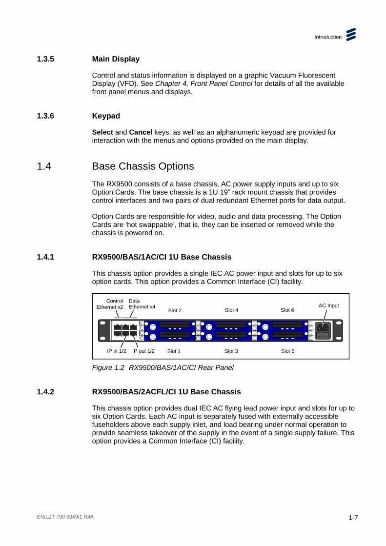
1.4.1 RX9500/BAS/1AC/CI 1U Base Chassis
This chassis option provides a single IEC AC power input and slots for up to six option cards. This option provides a Common Interface (CI) facility.
Figure 1.2 RX9500/BAS/1AC/CI Rear Panel
1.4.2 RX9500/BAS/2ACFL/CI 1U Base Chassis
This chassis option provides dual IEC AC flying lead power input and slots for up to six Option Cards. Each AC input is separately fused with externally accessible fuseholders above each supply inlet, and load bearing under normal operation to provide seamless takeover of the supply in the event of a single supply failure. This option provides a Common Interface (CI) facility.
Slot 2 Slot 4 Slot 6
Slot 1 Slot 3 Slot 5
AC Input Data Ethernet x4
Control Ethernet x2
IP in 1/2 IP out 1/2

Introduction
1-8 EN/LZT 790 0049/1 R4A
Figure 1.3 RX9500/BAS/2ACFL/CI Rear Panel
Slot 2 Slot 4 Slot 6
Slot 1 Slot 3 Slot 5
Data Ethernet x4
Control Ethernet x2 Dual AC Input
IP in 1/2 IP out 1/2

EN/LZT 790 0049/1 R4A 2-1
2 Installing the Equipment Chapter 2
Contents 2.1 Read This First! ................................................................................... 2-3 2.2 Mounting and Ventilation ..................................................................... 2-3 2.2.1 Fixing and Rack Mounting ................................................................... 2-3 2.2.2 Ventilation ........................................................................................... 2-3 2.3 Signal Connections.............................................................................. 2-4 2.3.1 Rear Panel Signal Connectors ............................................................ 2-4 2.3.2 Data Ethernet Connector ..................................................................... 2-4 2.3.3 Control Ethernet Connector ................................................................. 2-5 2.3.4 Satellite/IP Input CI Descrambler Card ................................................ 2-6
List of Figures
Figure 2.1 Air-Flow through the Equipment .......................................................... 2-3
List of Tables
Table 2.1 Data Ethernet Connector ..................................................................... 2-4 Table 2.2 Link Speed: Left (Green) LED ............................................................. 2-5 Table 2.3 Link Activity: Right (Yellow) LED.......................................................... 2-5 Table 2.4 Control Ethernet Connector ................................................................. 2-5 Table 2.5 Port Status: Left (Green) LED .............................................................. 2-6 Table 2.6 Link Activity: Right (Yellow) LED.......................................................... 2-6 Table 2.7 Satellite/IP Input CI Descrambler Card: RF Input Connector ............... 2-6

Installing the Equipment
2-2 EN/LZT 790 0049/1 R4A
BLANK
Installing the Equipment
EN/LZT 790 0049/1 R4A 2-3
2.1 Read This First! Please refer to the Installation, Safety and Compliance Information for Ericsson Compression Products Reference Guide supplied with your product for full details of installation requirements. This guide only contains additional product specific information where required.
2.2 Mounting and Ventilation
2.2.1 Fixing and Rack Mounting
The equipment is designed for fixed use only and has been shipped with fixing brackets suitable for a standard 19-inch rack. When installed in a rack, it should be secured using the fixing brackets. In addition, support shelves must be used to reduce the weight on the brackets. Ensure it is firmly and safely located and it has an adequate free-flow of air.
Slide the unit onto the chassis supports and affix to the rack by means of an M6 x 18 mm panhead screw in each corner.
A freestanding unit should be installed on a secure horizontal surface where it is unlikely to be knocked or its connectors and leads disturbed.
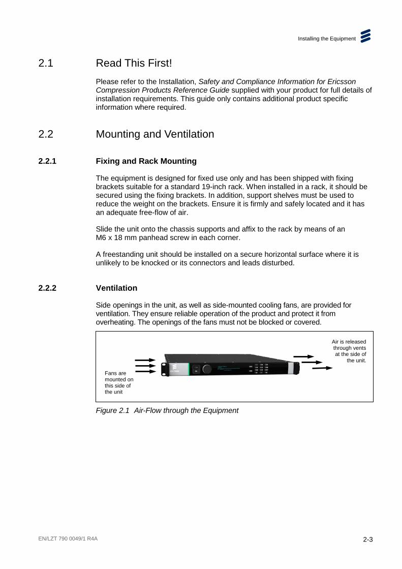
2.2.2 Ventilation
Side openings in the unit, as well as side-mounted cooling fans, are provided for ventilation. They ensure reliable operation of the product and protect it from overheating. The openings of the fans must not be blocked or covered.
Figure 2.1 Air-Flow through the Equipment
Air is released through vents at the side of
the unit.
Fans are mounted on this side of the unit

Installing the Equipment
2-4 EN/LZT 790 0049/1 R4A
2.3 Signal Connections
2.3.1 Rear Panel Signal Connectors
Caution!
It is strongly recommended that the terminal marked at the rear panel of the equipment is connected to a site Technical Earth before any external connections are made and the equipment is powered. This limits the migration of stray charges.
Signal connections are made via the rear panel. The rear panels, which are available are shown below. Full technical specifications for the connections are given in Annex B.
Only the Data and Control Ethernet connectors and the PSU connectors are mounted on the chassis. All other connections at the rear panel are provided with the option modules that may be fitted.
2.3.2 Data Ethernet Connector
The unit has four Ethernet ports - two for data input, and two for data output and will respond to ARPs, pings and other low-level Ethernet traffic. The ports are accessible via RJ-45 connectors on the rear panel of the chassis. These are labeled Ge 1, Ge 2, Ge 3 and Ge 4. Ge 1 and Ge 2 are used for data input, while Ge 3 and Ge 4 are data output.
Table 2.1 Data Ethernet Connector
Item Specification
Connector type RJ-45 (100/1000 Base T)
Connector designation Ge 1 (data input) Ge 2 (data input) Ge 3 (data output) Ge 4 (data output)
Pin outs (Unused pins are not connected)
Pin 1 - Tx Out (+) Pin 2 - Tx Out (-) Pin 3 - Rx In (+) Pin 6 - Rx In (-)
Installing the Equipment
EN/LZT 790 0049/1 R4A 2-5
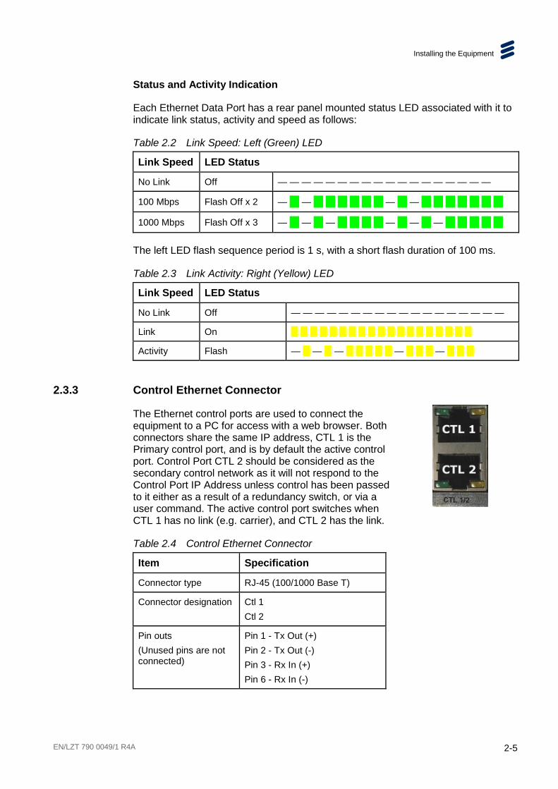
Status and Activity Indication
Each Ethernet Data Port has a rear panel mounted status LED associated with it to indicate link status, activity and speed as follows:
Table 2.2 Link Speed: Left (Green) LED
Link Speed LED Status
No Link Off — — — — — — — — — — — — — — — — — —
100 Mbps Flash Off x 2 — — — —
1000 Mbps Flash Off x 3 — — — — — —
The left LED flash sequence period is 1 s, with a short flash duration of 100 ms.
Table 2.3 Link Activity: Right (Yellow) LED
Link Speed LED Status
No Link Off — — — — — — — — — — — — — — — — — —
Link On
Activity Flash — — — — —
2.3.3 Control Ethernet Connector
The Ethernet control ports are used to connect the equipment to a PC for access with a web browser. Both connectors share the same IP address, CTL 1 is the Primary control port, and is by default the active control port. Control Port CTL 2 should be considered as the secondary control network as it will not respond to the Control Port IP Address unless control has been passed to it either as a result of a redundancy switch, or via a user command. The active control port switches when CTL 1 has no link (e.g. carrier), and CTL 2 has the link.
Table 2.4 Control Ethernet Connector
Item Specification
Connector type RJ-45 (100/1000 Base T)
Connector designation Ctl 1 Ctl 2
Pin outs (Unused pins are not connected)
Pin 1 - Tx Out (+) Pin 2 - Tx Out (-) Pin 3 - Rx In (+) Pin 6 - Rx In (-)

Installing the Equipment
2-6 EN/LZT 790 0049/1 R4A
Status and Activity Indication
Each Ethernet Control Port has rear panel mounted status LEDs to indicate link status, activity and speed as follows:
Table 2.5 Port Status: Left (Green) LED
Port Status
Link Speed
LED Status
Active Port
No Link Off — — — — — — — — — — — — — — — — — —
100 Mbps Flash Off x 2 — — — —
1000 Mbps Flash Off x 3 — — — — — —
Spare Port
No Link Off — — — — — — — — — — — — — — — — — —
100 Mbps Flash On x 2 — — — — — — — — — — — — — —
1000 Mbps Flash On x 3 — — — — — — — — — — — —
The left LED flash sequence period is 1 s, with a short flash duration of 100 ms.
Table 2.6 Link Activity: Right (Yellow) LED
Link Speed LED Status
No Link Off — — — — — — — — — — — — — — — — — —
Link On
Activity Flash — — — — —
2.3.4 Satellite/IP Input CI Descrambler Card
RF Input Connector
The Satellite/IP Input Common Interface (CI) Descrambler Card contains a single F-type connector for receiving RF input signals at up to 171 Mbps (DVB-S2). Each input is capable of routing incoming services via up to two Conditional Access Modules (CAM).
Table 2.7 Satellite/IP Input CI Descrambler Card: RF Input Connector
Item Specification
Connector type F-type, Female
Connector designation L-BAND INPUT
Pin-outs: Centre Shield
RF Output Ground/Chassis
Impedance 75 Ω
Installing the Equipment
EN/LZT 790 0049/1 R4A 2-7
Up to four RF inputs connect the L-band output of a suitable Low-Noise Block down-converter (LNB) to the unit either directly or via a suitable attenuator. The RF inputs may also be used to supply DC power to the LNB, if required.
Cautions!
The receiver provides DC power via the active L-band input connector to drive an LNB. Do not connect equipment other than an LNB to this connector. Failure to do this may result in damage to the external equipment.
The F-type connector is not suitable for repeated connection and disconnection. When intended for use in this way, fit a sacrificial connector and connect to it.
See Chapter 7, Options, Licensing and Upgrades for further details about this card’s features and see Annex B, Technical Specification for a detailed specification.

Installing the Equipment
2-8 EN/LZT 790 0049/1 R4A
BLANK

EN/LZT 790 0049/1 R4A 3-1
3 Getting Started Chapter 3
Contents 3.1 Introduction ......................................................................................... 3-3 3.2 How to Connect Up the Unit ................................................................ 3-3 3.3 How to Power Up the Unit ................................................................... 3-4 3.4 How to Set the Unit IP Address ........................................................... 3-4 3.5 How to View the Web GUI ................................................................... 3-6 3.6 How to Monitor Your Unit Status and Alarms ....................................... 3-7 3.7 How to Configure Alarm Masking and Severity .................................... 3-9 3.8 How to Configure Data Interfaces and Redundancy .......................... 3-10 3.9 How to Add Option Cards and Conditional Access Modules
(CAMs) .............................................................................................. 3-11 3.10 How to Configure/Tune Option Cards ................................................ 3-12 3.11 How to View Input Transport Streams, Services and Components .... 3-13 3.12 How to Create a New Output Transport Stream ................................ 3-13 3.13 How to Delete a Transport Stream .................................................... 3-15 3.14 How to Quickly Copy/Configure Transport Streams, Services and
Components ...................................................................................... 3-15 3.15 How to Configure Descrambling or Passthrough ............................... 3-16 3.16 How to Add and Configure Service Passthrough and IP Input
Transport Stream .............................................................................. 3-18 3.17 How to Apply or Discard Configuration Changes ............................... 3-24 3.18 How to Save and Restore Your Configurations .................................. 3-25 3.19 How to Generate Log Files ................................................................ 3-26 3.20 How to Order and Apply Additional Licenses ..................................... 3-27
List of Figures Figure 3.1 RX9500 Connections ........................................................................ 3-3 Figure 3.2 Web GUI - Dashboard Page .............................................................. 3-6 Figure 3.3 Viewing Alarms on the Front Panel .................................................... 3-7 Figure 3.4 Viewing Alarms on the Dashboard ..................................................... 3-8 Figure 3.5 Viewing Alarms on the Monitoring > Alarms Page ............................. 3-8 Figure 3.6 Configuring and Masking Alarms ....................................................... 3-9 Figure 3.7 Selecting an Alarm to Modify ............................................................. 3-9 Figure 3.8 Selecting Alarm Severity/Masking ................................................... 3-10 Figure 3.9 Changed Alarm Severity/Masking.................................................... 3-10 Figure 3.10 Dashboard Displaying the Number of Option Cards Fitted .............. 3-11 Figure 3.11 Viewing/Configuring Input Option Card Properties .......................... 3-12

Getting Started
3-2 EN/LZT 790 0049/1 R4A
Figure 3.12 Viewing Input Transport Streams and Services ............................... 3-13 Figure 3.13 Adding an Output Transport Stream ................................................ 3-14 Figure 3.14 Setting Output Transport Stream Properties.................................... 3-14 Figure 3.15 Confirm Deletion Dialog Box ........................................................... 3-15 Figure 3.16 Descramble Assistant Wizard – CAM Allocation .............................. 3-16 Figure 3.17 Descramble Assistant Wizard – IP Input Configuration ................... 3-17 Figure 3.18 Descramble Assistant Wizard – Preview ......................................... 3-17 Figure 3.19 Selecting the Multiplex for Demodulation ........................................ 3-19 Figure 3.20 Dragging-and-Dropping the Multiplex for Demodulation .................. 3-20 Figure 3.21 Viewing the List of Services ............................................................ 3-20 Figure 3.22 Modifying the Outgoing IP MPTS Properties ................................... 3-21 Figure 3.23 Setting the Outgoing Multicast IP Address ...................................... 3-21 Figure 3.24 Setting the Outgoing IP Bit Rate ..................................................... 3-22 Figure 3.26 Selecting the Service for Passthrough ............................................ 3-22 Figure 3.27 The Services Selected for Descrambling ........................................ 3-23 Figure 3.28 Selecting a Free-to-air Service for Passthrough .............................. 3-23 Figure 3.29 Selecting Services for Descramble or Passthrough ........................ 3-24 Figure 3.30 Property Changes Highlighted in Orange ........................................ 3-24 Figure 3.31 Apply and Discard Buttons .............................................................. 3-24 Figure 3.32 Discarding Confirmation Dialog ....................................................... 3-25 Figure 3.33 Importing and Exporting Configurations .......................................... 3-25 Figure 3.34 Saving Unit Configurations ............................................................. 3-26 Figure 3.35 Generating a Log File ..................................................................... 3-27 Figure 3.36 Viewing Your Licenses .................................................................... 3-27
List of Tables Table 3.1 IP Address Restrictions ..................................................................... 3-5

Getting Started
EN/LZT 790 0049/1 R4A 3-3
3.1 Introduction This chapter provides general guidance and principles on how to power up and set up your unit for operation and describes the more common operations you will want to perform.
For details of all Front Panel menus and controls, see Chapter 4, Front Panel Control. For details of all Web Graphical User Interface (GUI) menus and controls, see Chapter 5, Web GUI Control.
For more information on possible networking scenarios, see Chapter 6, Advanced Video Processing and Networking.
3.2 How to Connect Up the Unit See Chapter 2, Installing the Equipment for all connector details.
Figure 3.1 RX9500 Connections

Getting Started
3-4 EN/LZT 790 0049/1 R4A
To connect up the unit(s):
1. Connect your L-band signal cables to/from your option cards, depending on which options are licensed for your unit.
2. Connect your IP signal cables to/from the input connectors Ge1 and Ge2 (for your input Transport Streams), depending on which options are licensed for your unit.
3. Connect signal output connectors Ge 3 and Ge 4 (for your output Transport Streams) to your local area network.
4. Connect computer control connectors CTL1 and CTL2 (for Web GUI Control) to your local area network. Both connectors share the same IP address, Ctrl1 is the Primary control port, and is by default the active control port. Control Port Ctrl2 should be considered as the secondary control network as it will not respond to the Control Port IP Address unless control has been passed to it either as a result of a redundancy switch, or via a user command. The active control port switches when Ctrl1 has no link (e.g. carrier), and Ctrl2 has the link.
5. Connect single or dual AC power connectors, depending on the option purchased, to the power supply.
3.3 How to Power Up the Unit
Caution!
This equipment should not be operated unless the cooling fans are working and there is free-air flow around the unit.
To power up the unit(s):
1. With all signal and power cables connected as required, switch on the power supply outlet to the unit.
2. Switch on the unit using the power on/off (I/O) switch on the front panel, located to the left of the rotary control knob.
3. Wait for unit initialisation to complete (approximately 1.5 to 3 minutes, depending on the number of options fitted in the unit).
3.4 How to Set the Unit IP Address Setting the IP address of a unit is accomplished using the front panel menus. For a full description of these menus, see Chapter 4, Front Panel Control.
To set the IP address of the unit(s):
1. Ensure the unit is fully powered up.
Getting Started
EN/LZT 790 0049/1 R4A 3-5
2. On the front panel, using the rotary knob, scroll down to the System > Remote Control Setup> IP Address option.
3. Press knob to select.
4. Using the keys on the keypad, set the IP address, subnet mask and gateway address, as required.
5. Press the Select button to save or Cancel to discard the changes.
Note: It may be necessary to set the subnet mask to 0 in order to allow the IP address to be changed.
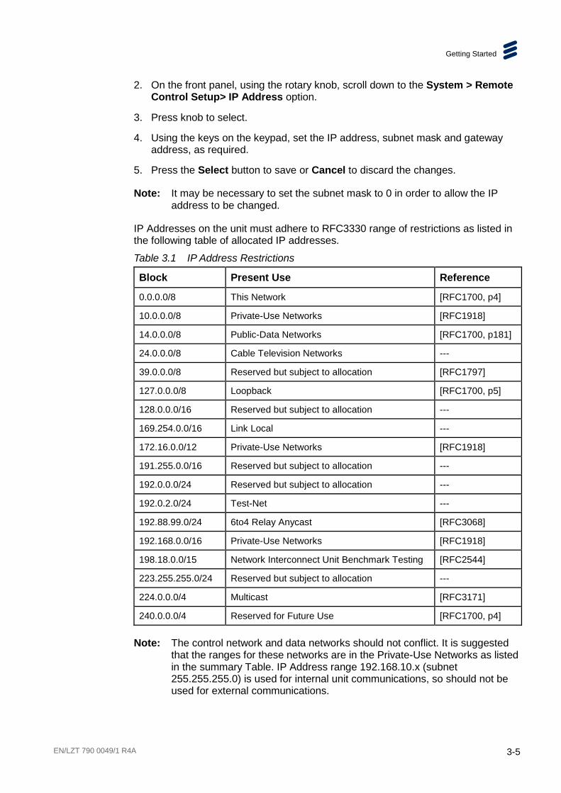
IP Addresses on the unit must adhere to RFC3330 range of restrictions as listed in the following table of allocated IP addresses.
Table 3.1 IP Address Restrictions
Block Present Use Reference
0.0.0.0/8 This Network [RFC1700, p4]
10.0.0.0/8 Private-Use Networks [RFC1918]
14.0.0.0/8 Public-Data Networks [RFC1700, p181]
24.0.0.0/8 Cable Television Networks ---
39.0.0.0/8 Reserved but subject to allocation [RFC1797]
127.0.0.0/8 Loopback [RFC1700, p5]
128.0.0.0/16 Reserved but subject to allocation ---
169.254.0.0/16 Link Local ---
172.16.0.0/12 Private-Use Networks [RFC1918]
191.255.0.0/16 Reserved but subject to allocation ---
192.0.0.0/24 Reserved but subject to allocation ---
192.0.2.0/24 Test-Net ---
192.88.99.0/24 6to4 Relay Anycast [RFC3068]
192.168.0.0/16 Private-Use Networks [RFC1918]
198.18.0.0/15 Network Interconnect Unit Benchmark Testing [RFC2544]
223.255.255.0/24 Reserved but subject to allocation ---
224.0.0.0/4 Multicast [RFC3171]
240.0.0.0/4 Reserved for Future Use [RFC1700, p4]
Note: The control network and data networks should not conflict. It is suggested that the ranges for these networks are in the Private-Use Networks as listed in the summary Table. IP Address range 192.168.10.x (subnet 255.255.255.0) is used for internal unit communications, so should not be used for external communications.

Getting Started
3-6 EN/LZT 790 0049/1 R4A
3.5 How to View the Web GUI The unit’s many features and parameters may all be configured using the web browser Graphical User Interface (GUI). For details of all the GUI screens, see Chapter 5, Web GUI Control.
Recommended Internet Browser
It is recommended that Internet Explorer version 9 (IE9) or Google Chrome is used to access the web user interface. When using Internet Explorer 9, it is recommended that the Developer Tools Cache configuration is set to Always Refresh from Server.
To configure browser refresh:
1. Select Tools > Developer Tools in the Internet Explorer browser menu.
2. Select Cache > Always Refresh from Server from the Developer Tools menu.
Viewing the Web GUI
To view the web GUI:
1. Ensure the laptop/computer console is connected to the CTL1 port on the unit.
2. Open/run the web browser.
3. Type the IP address of the unit into the web browser. The web GUI Dashboard screen will be displayed. Access to the GUI is password protected.
Figure 3.2 Web GUI - Dashboard Page
4. Type the Username (user) and Password (access) to gain access to the GUI screens and menus used to control, configure and monitor the unit.

Getting Started
EN/LZT 790 0049/1 R4A 3-7
For details of how to use the web GUI pages and for detailed descriptions of all the features, options and parameters, see Chapter 5, Web GUI Control.
3.6 How to Monitor Your Unit Status and Alarms Alarms are reported on the web GUI Dashboard and Monitoring pages, and also on the Front Panel. Alarm trap handling is also supported through SNMP.
Monitoring Alarms Using the Front Panel
To monitor alarms using the unit Front Panel:
1. The default display on the unit Front Panel lists the current active alarm, its severity and the number of alarms [in brackets].
Control IP 172.017.100.033 Alarm: Major [2] Standalone: Active
Figure 3.3 Viewing Alarms on the Front Panel
2. To view a complete list of all the active alarms, navigate to the System > Alarms screen. See Chapter 4, Front Panel Control for a full description of alarm messages and states.
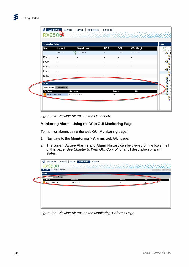
Monitoring Alarms Using the Web GUI Dashboard Page
To monitor alarms using the web GUI Dashboard:
1. Navigate to the Dashboard web GUI page.
2. The current Active Alarms and Alarm History can be viewed on the lower half of this page. See Chapter 5, Web GUI Control for a full description of alarm states.
Getting Started
3-8 EN/LZT 790 0049/1 R4A
Figure 3.4 Viewing Alarms on the Dashboard
Monitoring Alarms Using the Web GUI Monitoring Page
To monitor alarms using the web GUI Monitoring page:
1. Navigate to the Monitoring > Alarms web GUI page.
2. The current Active Alarms and Alarm History can be viewed on the lower half of this page. See Chapter 5, Web GUI Control for a full description of alarm states.
Figure 3.5 Viewing Alarms on the Monitoring > Alarms Page

Getting Started
EN/LZT 790 0049/1 R4A 3-9
3.7 How to Configure Alarm Masking and Severity Alarms can be masked (ignored/silenced) or their severity modified (critical, major, minor or warning), enabling you to customize the reporting of alarms to suit your requirements.
To configure alarm masking or severity:
1. Navigate to the Monitoring > Alarm Overrides page on the web GUI.
Figure 3.6 Configuring and Masking Alarms
2. Select the alarm description that you wish to modify by either placing a check mark in the relevant check box or by clicking on the alarm description.
Figure 3.7 Selecting an Alarm to Modify
3. Click on the currently displayed severity value (critical, major, minor, warning or mask) in the Overridden Severity column to display a drop-down box and select the required value for this alarm.

Getting Started
3-10 EN/LZT 790 0049/1 R4A
Figure 3.8 Selecting Alarm Severity/Masking
4. To save your changes, click the Apply button. The new alarm severity will now be displayed in the Overridden Severity column.
Figure 3.9 Changed Alarm Severity/Masking
5. All overridden alarms can be viewed, and modified, by clicking on the Alarm Dictionary / Overridden Alarms filter at the top of the table. See Chapter 5, Web GUI Control for a full description of alarm states.
3.8 How to Configure Data Interfaces and Redundancy The unit may be used in one of several redundancy modes, which determine whether both IP outputs stream content at the same time:
• Active-Active Mode – Both data interfaces stream the same multicast at the same time.
To configure the data interfaces and redundancy:
1. Navigate to the Device > Network screen on the web GUI.
Getting Started
EN/LZT 790 0049/1 R4A 3-11
2. Select the relevant Data Interface Group by clicking on it in the Network Interfaces widget.
3. In the Properties widget, select the required Redundancy Mode. Ensure that the correct cabling has been connected to the rear panel data interface connectors to construct the required redundancy configuration.
4. Enter the required IP address, subnet and gateway settings for the Interfaces in the Properties widget.
5. To save your changes, click the Apply button.
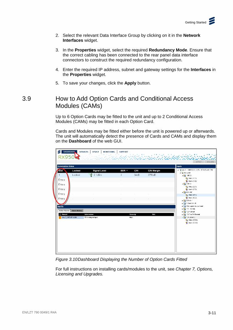
3.9 How to Add Option Cards and Conditional Access Modules (CAMs) Up to 6 Option Cards may be fitted to the unit and up to 2 Conditional Access Modules (CAMs) may be fitted in each Option Card.
Cards and Modules may be fitted either before the unit is powered up or afterwards. The unit will automatically detect the presence of Cards and CAMs and display them on the Dashboard of the web GUI.
Figure 3.10 Dashboard Displaying the Number of Option Cards Fitted
For full instructions on installing cards/modules to the unit, see Chapter 7, Options, Licensing and Upgrades.

Getting Started
3-12 EN/LZT 790 0049/1 R4A
3.10 How to Configure/Tune Option Cards Each Option Card fitted to the unit is automatically listed in the Inputs widget of the Services > Configure page. It must be correctly configured (tuned) in order to receive the Transport Streams and Input Services present on the received signal.
To configure/tune an Option Card:
1. Navigate to the Services > Configure screen on the web GUI.
2. Click on the relevant Card in the Inputs widget. The parameters for this card are then displayed in the Properties widget on the right-hand side of the window.
Figure 3.11 Viewing/Configuring Input Option Card Properties
3. In the Properties widget, select the required parameters under Tuning Properties (LNB LO Frequency, Satellite Frequency, etc.) for the expected received signal on the Card. See Chapter 5, Web GUI Control for details of this page and these properties.
4. To save your changes, click the Apply button.
5. When the Card properties have been configured and it is tuned to receive the expected signal, the signal properties will be displayed at the top of the Properties widget under Status. The Transport Streams and Input Services will be automatically displayed in the Inputs widget.

Getting Started
EN/LZT 790 0049/1 R4A 3-13
3.11 How to View Input Transport Streams, Services and Components Transport Streams received at the Option Card L-Band inputs are automatically detected and listed in the Input pane on the Services > Configure web page.
Figure 3.12 Viewing Input Transport Streams and Services
The Transport Streams, Services and Components (video, audio and data) are listed in Option Card order in a tree structure, beginning with Card 1 at the top.
To view Transport Streams, Services and Components, click on the triangle (node) alongside each item in the displayed tree structure to expand or collapse and reveal or hide further detail.
To quickly expand or collapse the tree structure at a particular point, double-click on the item.
3.12 How to Create a New Output Transport Stream Any or all input Transport Streams, Services and Components (video, audio and data) received and displayed in the Inputs widget can be selected for use by the unit i.e., for descrambling or passthrough.
A new output Transport Stream may be created from scratch if you want to define new services and configure new settings for it. Alternatively, you could simply copy an existing Transport Stream and modify the services and settings, which in most cases will be quicker (see section 3.14 How to Quickly Copy/Configure Transport Streams, Services and Components).
To create new Output Transport Stream:
1. Navigate to the Service > Configure web page.
2. To create a new Transport Stream, either right-click on the Outputs widget, or
simply click on the icon above at the top of the Outputs widget, and then click on the displayed Add Transport Stream menu option.

Getting Started
3-14 EN/LZT 790 0049/1 R4A
Figure 3.13 Adding an Output Transport Stream
3. A new Transport Stream (highlighted in orange, signifying it is new and unsaved) is added to the list in the Outputs widget and the associated settings for the Transport Stream are displayed in the Properties widget (again, highlighted in orange).
Figure 3.14 Setting Output Transport Stream Properties
4. Enter/modify the Transport Stream properties as required for your system installation. See Chapter 5, Web GUI Control for a detailed description of these properties.
5. To save your changes, click the Apply button.

Getting Started
EN/LZT 790 0049/1 R4A 3-15
3.13 How to Delete a Transport Stream To delete a Transport Stream:
1. Navigate to the Service > Configure web page.
2. Click on the Transport Stream you wish to delete (in either the Inputs or Outputs widget).
3. Click on the wastebasket icon or select Delete Transport Stream from the right-click menu. A confirmation dialog box will be displayed.
Figure 3.15 Confirm Deletion Dialog Box
4. Click Yes to delete. The Transport Stream will be deleted from the widget.
3.14 How to Quickly Copy/Configure Transport Streams, Services and Components The drag-and-drop method is useful when you want to quickly configure Transport Streams and Services for descrambling that are largely or wholly unchanged from the received input.
To enable copy/configure Transport Streams and Services:
1. Navigate to the Service > Configure web page.
2. Ensure that Transport Streams and Services are displayed in the Inputs widget.
3. Click on the required Transport Stream or Service, drag it from the Input widget. To select more than one item, use either Shift-click to select adjacent items or Ctrl-click to select non-adjacent items.
4. Drop the selected item(s) either onto an existing Transport Stream in the Outputs widget to add it to that stream, or onto the white space at the bottom of the Outputs pane to create a new stream and display the Descramble Assistant wizard (see section 3.15 How to Configure Descrambling or Passthrough).
5. Modify the Properties as required for the Services copied. See Chapter 5, Web GUI Control for a detailed description of these properties.
6. To save your changes, click the Apply button.
Getting Started
3-16 EN/LZT 790 0049/1 R4A
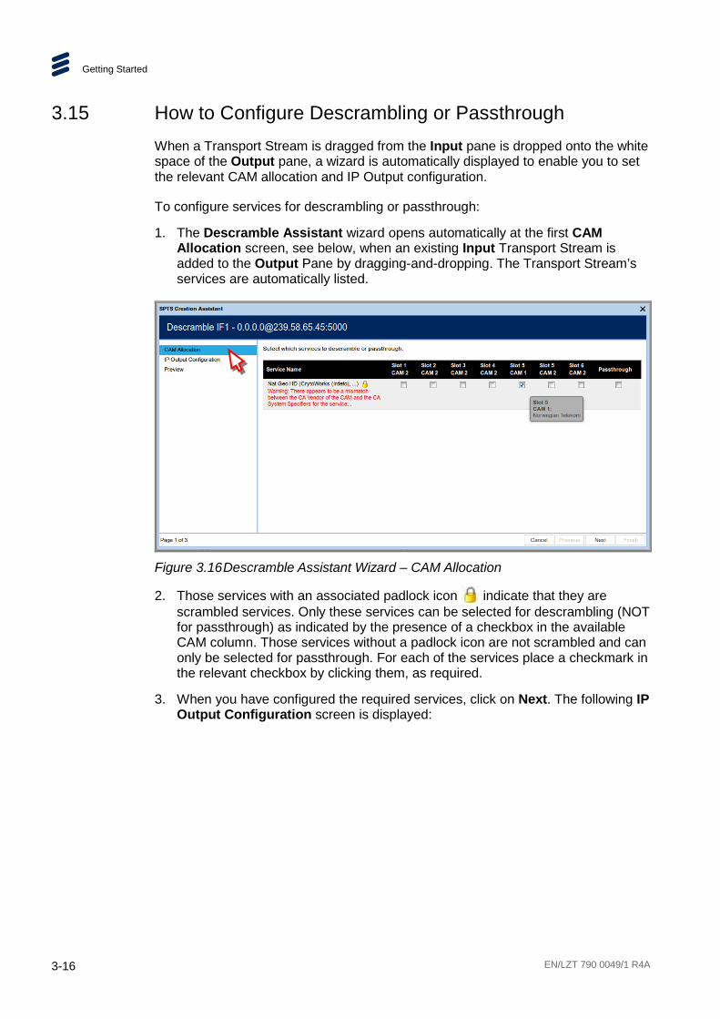
3.15 How to Configure Descrambling or Passthrough When a Transport Stream is dragged from the Input pane is dropped onto the white space of the Output pane, a wizard is automatically displayed to enable you to set the relevant CAM allocation and IP Output configuration.
To configure services for descrambling or passthrough:
1. The Descramble Assistant wizard opens automatically at the first CAM Allocation screen, see below, when an existing Input Transport Stream is added to the Output Pane by dragging-and-dropping. The Transport Stream’s services are automatically listed.
Figure 3.16 Descramble Assistant Wizard – CAM Allocation
2. Those services with an associated padlock icon indicate that they are scrambled services. Only these services can be selected for descrambling (NOT for passthrough) as indicated by the presence of a checkbox in the available CAM column. Those services without a padlock icon are not scrambled and can only be selected for passthrough. For each of the services place a checkmark in the relevant checkbox by clicking them, as required.
3. When you have configured the required services, click on Next. The following IP Output Configuration screen is displayed:
Getting Started
EN/LZT 790 0049/1 R4A 3-17
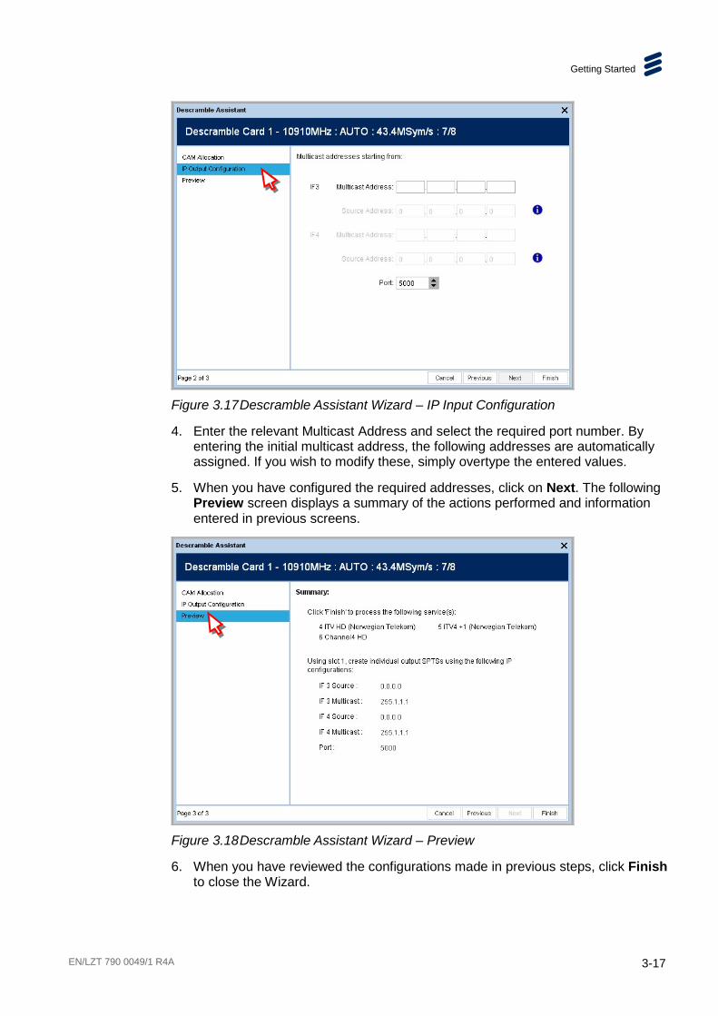
Figure 3.17 Descramble Assistant Wizard – IP Input Configuration
4. Enter the relevant Multicast Address and select the required port number. By entering the initial multicast address, the following addresses are automatically assigned. If you wish to modify these, simply overtype the entered values.
5. When you have configured the required addresses, click on Next. The following Preview screen displays a summary of the actions performed and information entered in previous screens.
Figure 3.18 Descramble Assistant Wizard – Preview
6. When you have reviewed the configurations made in previous steps, click Finish to close the Wizard.

Getting Started
3-18 EN/LZT 790 0049/1 R4A
3.16 How to Add and Configure Service Passthrough and IP Input Transport Stream RX9500 can be deployed in ways that provide flexibility to the user. Some users implementing a content turn-around solution choose to, or are forced to site their down-link satellite farm in a geographical location that is remote from the headend site. To allow users to implement solutions around this scenario RX9500 can be deployed to implement bulk demodulation at the down-link site with IP TS output and bulk descramble with IP TS input at the headend site – allowing IP connectivity between the two sites.
Figure 3.19 Remotely Located Down-link and Headend
In applications where a separate down-link site is employed, an RX9500 is installed at the down-link location to provide a bulk demodulation function. A second RX9500 is installed at the headend site to provide a bulk descrambling function. Descrambled services can then be passed from the 2nd RX9500 unit to a subsequent transcode or video monitoring process.
The RX9500 at the down-link site can be configured to demodulate the satellite services of interest. This “demodulation” RX9500 unit can be set to pass only the services that are required for subsequent descrambling over the IP network. Each service filtered satellite multiplex is sent as an MPTS stream over the IP network. The 2nd “descrambling” RX9500 then performs Common Interface descrambling on the received services outputting each descrambled service as individual SPTSs.
If, as part of the required new service line-up some satellite services exist as Free-to-Air (FTA) on the satellite transponder, these FTA services can simply be routed directly from the “demodulation” RX9500 to the transcode head-end (bypassing the second “descrambling” RX9500).
Getting Started
EN/LZT 790 0049/1 R4A 3-19
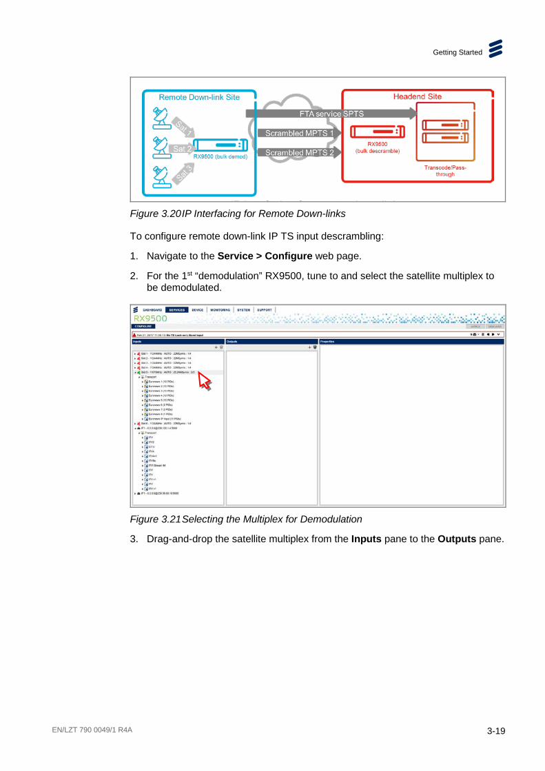
Figure 3.20 IP Interfacing for Remote Down-links
To configure remote down-link IP TS input descrambling:
1. Navigate to the Service > Configure web page.
2. For the 1st “demodulation” RX9500, tune to and select the satellite multiplex to be demodulated.
Figure 3.21 Selecting the Multiplex for Demodulation
3. Drag-and-drop the satellite multiplex from the Inputs pane to the Outputs pane.

Getting Started
3-20 EN/LZT 790 0049/1 R4A
Figure 3.22 Dragging-and-Dropping the Multiplex for Demodulation
4. Click on the triangle at the left of the output satellite multiplex to view the list of services.
Figure 3.23 Viewing the List of Services
5. Configure the outgoing IP MPTS parameters in the Properties pane.
Getting Started
EN/LZT 790 0049/1 R4A 3-21
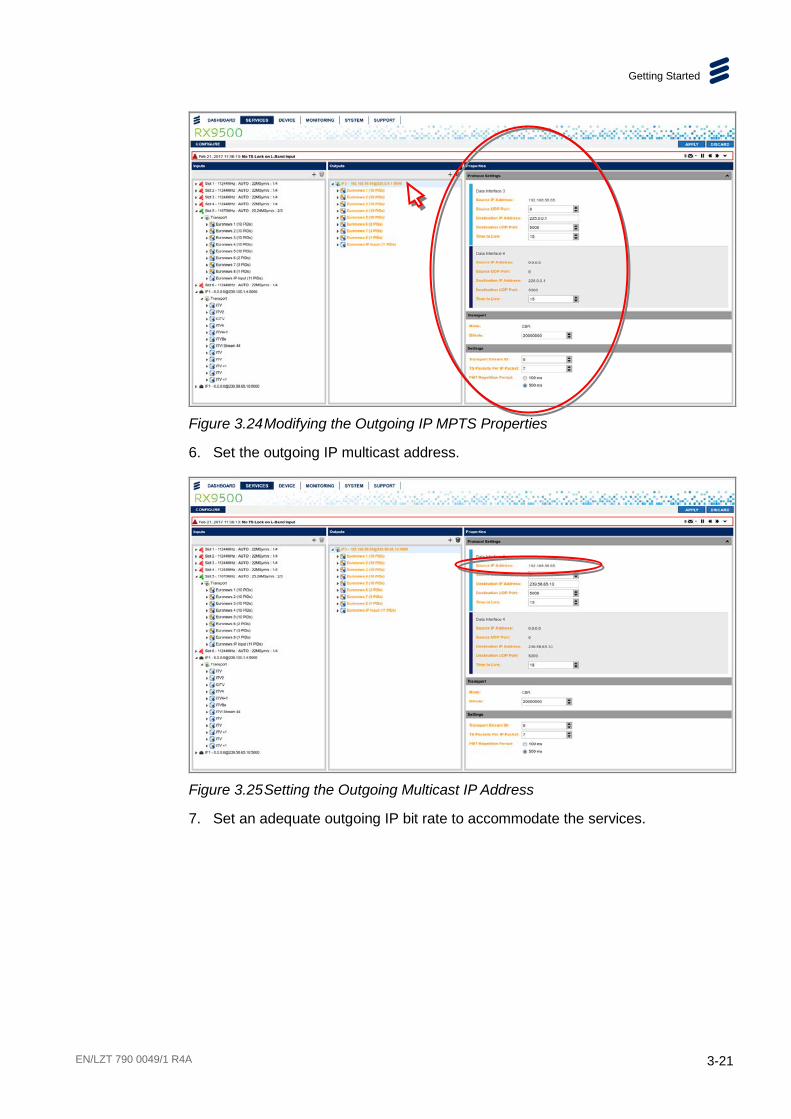
Figure 3.24 Modifying the Outgoing IP MPTS Properties
6. Set the outgoing IP multicast address.
Figure 3.25 Setting the Outgoing Multicast IP Address
7. Set an adequate outgoing IP bit rate to accommodate the services.

Getting Started
3-22 EN/LZT 790 0049/1 R4A
Figure 3.26 Setting the Outgoing IP Bit Rate
8. To save your changes, click the Apply button.
9. Select the services NOT required to be passed on for descrambling, by using Shift + click or Ctrl + click.
Figure 3.27 Selecting the Service for Passthrough
10. Delete the services not required for subsequent descrambling by clicking on the trash can icon. Now only the ‘wanted’ services are present in the outgoing multicast.

Getting Started
EN/LZT 790 0049/1 R4A 3-23
Figure 3.28 The Services Selected for Descrambling
11. To save your changes, click the Apply button.
12. If a FTA service is required to be passed from the “demodulation” RX9500 to a subsequent transcode stage then this can be added as an outgoing Single Program Transport Stream (SPTS) by dragging-and-dropping the service from the Inputs pane to the Outputs pane.
Figure 3.29 Selecting a Free-to-air Service for Passthrough
13. In the displayed dialog, select to be passed-through without attempting any descrambling.

Getting Started
3-24 EN/LZT 790 0049/1 R4A
Figure 3.30 Selecting Services for Descramble or Passthrough
Note: If during this configuration process the RX9500 presents a “Routing Error” then this is an indication that the maximum PID limit of the device has been reached. Reduce the service load or satellite transponder usage on receiver or utilise more RX9500 units to accommodate your needs.
3.17 How to Apply or Discard Configuration Changes All modifications to a configuration initially only appear in the web GUI. All changes made to Service and Profile properties are highlighted as orange text to enable you to see the changes at a glance.
Figure 3.31 Property Changes Highlighted in Orange
The unit will not accept any changes to properties until the Apply button, located in the top right-hand corner of the window, is clicked.
Figure 3.32 Apply and Discard Buttons
Note: Changing some parameters during operation may cause output glitching. Changing the output bit rate will not cause a glitch.
Getting Started
EN/LZT 790 0049/1 R4A 3-25
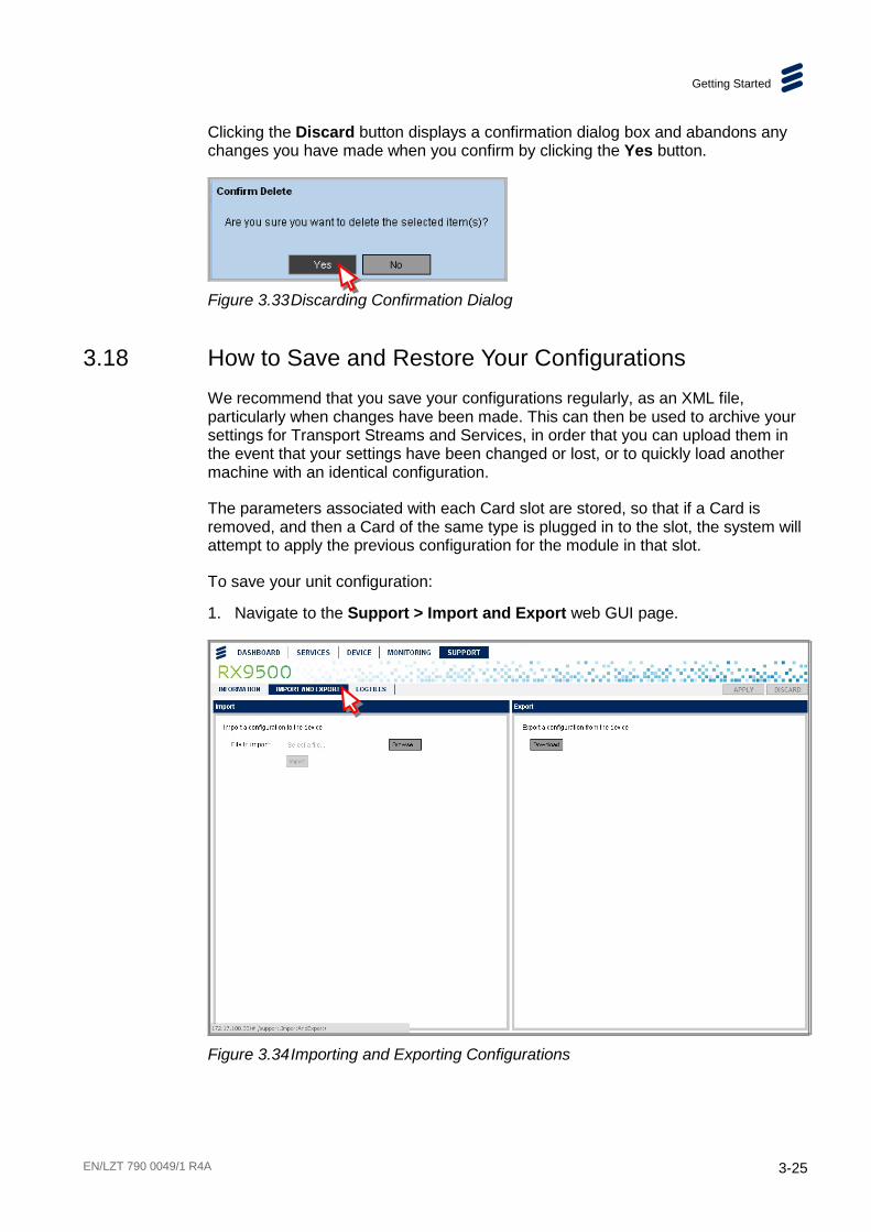
Clicking the Discard button displays a confirmation dialog box and abandons any changes you have made when you confirm by clicking the Yes button.
Figure 3.33 Discarding Confirmation Dialog
3.18 How to Save and Restore Your Configurations We recommend that you save your configurations regularly, as an XML file, particularly when changes have been made. This can then be used to archive your settings for Transport Streams and Services, in order that you can upload them in the event that your settings have been changed or lost, or to quickly load another machine with an identical configuration.
The parameters associated with each Card slot are stored, so that if a Card is removed, and then a Card of the same type is plugged in to the slot, the system will attempt to apply the previous configuration for the module in that slot.
To save your unit configuration:
1. Navigate to the Support > Import and Export web GUI page.
Figure 3.34 Importing and Exporting Configurations
Getting Started
3-26 EN/LZT 790 0049/1 R4A
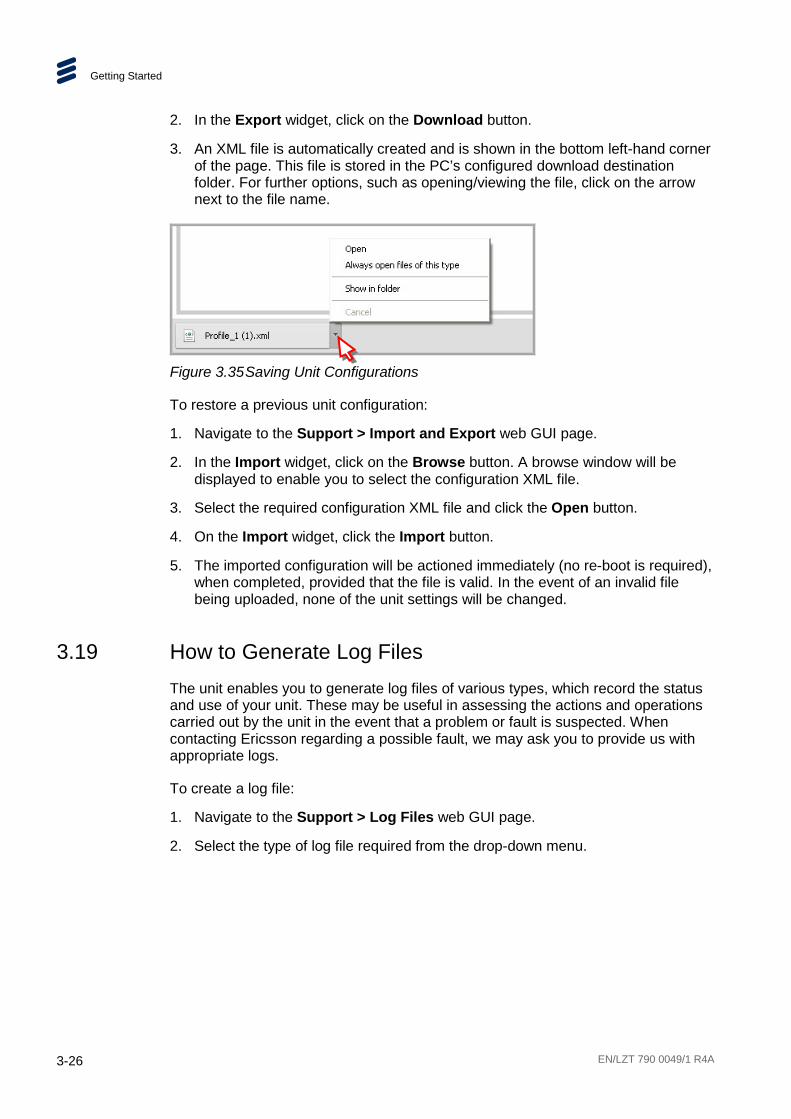
2. In the Export widget, click on the Download button.
3. An XML file is automatically created and is shown in the bottom left-hand corner of the page. This file is stored in the PC’s configured download destination folder. For further options, such as opening/viewing the file, click on the arrow next to the file name.
Figure 3.35 Saving Unit Configurations
To restore a previous unit configuration:
1. Navigate to the Support > Import and Export web GUI page.
2. In the Import widget, click on the Browse button. A browse window will be displayed to enable you to select the configuration XML file.
3. Select the required configuration XML file and click the Open button.
4. On the Import widget, click the Import button.
5. The imported configuration will be actioned immediately (no re-boot is required), when completed, provided that the file is valid. In the event of an invalid file being uploaded, none of the unit settings will be changed.
3.19 How to Generate Log Files The unit enables you to generate log files of various types, which record the status and use of your unit. These may be useful in assessing the actions and operations carried out by the unit in the event that a problem or fault is suspected. When contacting Ericsson regarding a possible fault, we may ask you to provide us with appropriate logs.
To create a log file:
1. Navigate to the Support > Log Files web GUI page.
2. Select the type of log file required from the drop-down menu.
Getting Started
EN/LZT 790 0049/1 R4A 3-27
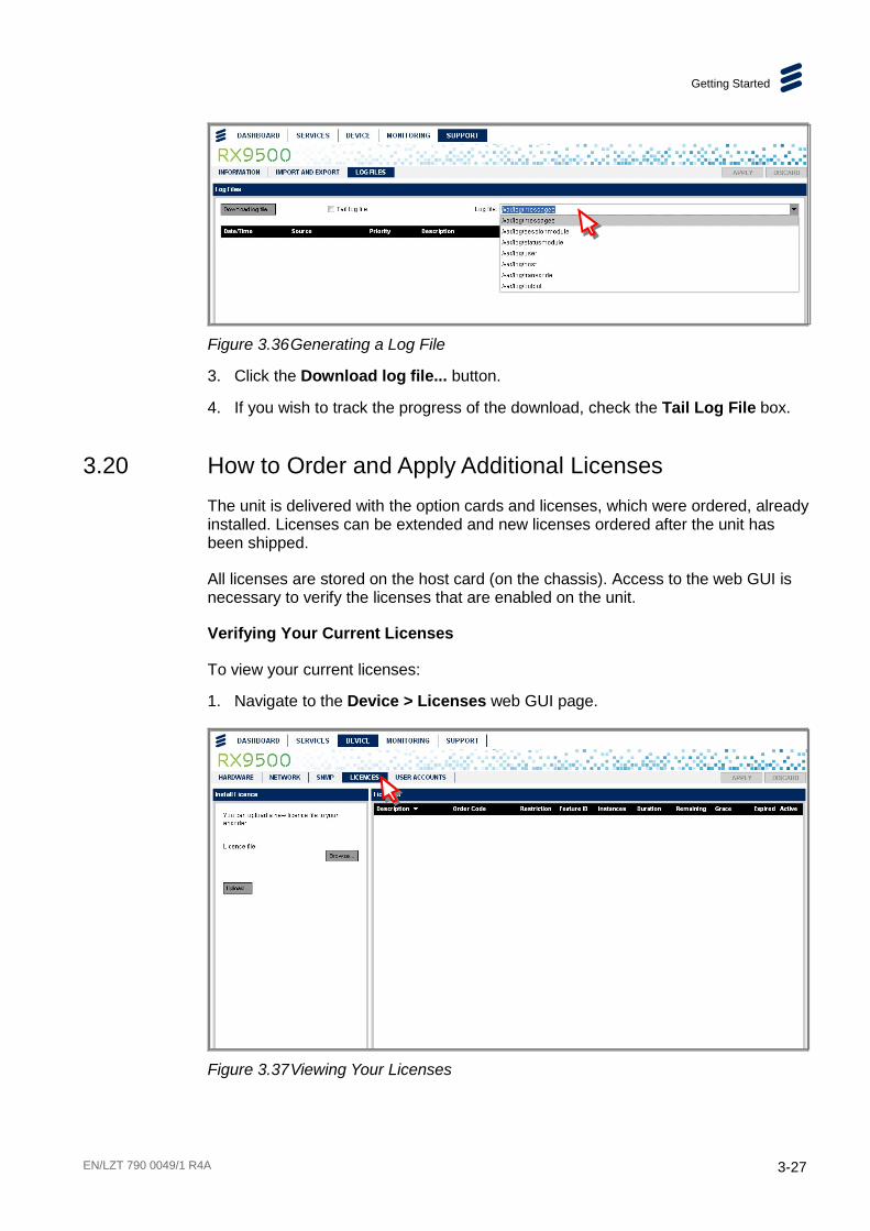
Figure 3.36 Generating a Log File
3. Click the Download log file... button.
4. If you wish to track the progress of the download, check the Tail Log File box.
3.20 How to Order and Apply Additional Licenses The unit is delivered with the option cards and licenses, which were ordered, already installed. Licenses can be extended and new licenses ordered after the unit has been shipped.
All licenses are stored on the host card (on the chassis). Access to the web GUI is necessary to verify the licenses that are enabled on the unit.
Verifying Your Current Licenses
To view your current licenses:
1. Navigate to the Device > Licenses web GUI page.
Figure 3.37 Viewing Your Licenses
Getting Started
3-28 EN/LZT 790 0049/1 R4A
2. All your current licenses are listed in the License widget on the right-hand side of the page, including information regarding their remaining time and whether they are expired or active.
Installing Additional/New Licenses
To install additional/new licenses:
1. Navigate to the Device > Licenses web GUI page.
2. In the Install License widget, click the Browse button to locate the license key file.
3. Click on the Upload button.
4. If licenses are required for both the base chassis and option card then multiple files will be provided which all need to be loaded onto the specific unit.
5. Re-boot the unit for the changes to take effect.
Note: The front panel CANNOT be used to upload license keys.

EN/LZT 790 0049/1 R4A 4-1
4 Front Panel Control Chapter 4
Contents 4.1 Introduction ......................................................................................... 4-3 4.2 Using the Front Panel Controls ............................................................ 4-3 4.2.1 Status (Light) Bar ................................................................................ 4-3 4.2.2 Power Switch ....................................................................................... 4-3 4.2.3 Mini USB ............................................................................................. 4-4 4.2.4 Rotary Knob and Main Display ............................................................ 4-4 4.2.5 Keypad ................................................................................................ 4-4 4.3 Front Panel Menus .............................................................................. 4-5 4.4 Front Panel Menu Descriptions ........................................................... 4-6 4.4.1 Top-Level Menu .................................................................................. 4-6 4.4.2 System Menu ...................................................................................... 4-6 4.4.3 System > Remote Control ................................................................... 4-6 4.4.3.1 System > Remote Control > IP Address .............................................. 4-6 4.4.3.2 System > Remote Control > Subnet Mask ........................................... 4-7 4.4.3.3 System > Remote Control > Gateway Address .................................... 4-7 4.4.3.4 System > Remote Control > Default MAC Address.............................. 4-7 4.4.4 System > Alarms ................................................................................. 4-8 4.4.4.1 System > Alarms > (Detail) .................................................................. 4-8 4.4.5 System > Versions .............................................................................. 4-9 4.4.5.1 System > Versions > Hardware Versions ............................................ 4-9 4.4.5.2 System > Versions > Software Versions .............................................. 4-9 4.4.5.3 System > Versions > Assembly Date ................................................... 4-9 4.4.5.4 System > Versions > Serial Number .................................................. 4-10 4.4.5.5 System > Versions > Chassis Identity................................................ 4-10 4.4.6 System > Redundancy ...................................................................... 4-10 4.4.7 System > Redundancy Status ........................................................... 4-11 4.4.8 System > Restore Factory Defaults ................................................... 4-11 4.4.9 System > Switch Boot Bank .............................................................. 4-11
List of Figures Figure 4.1 RX9500 Front Panel ............................................................................ 4-3 Figure 4.2 Status Bar, Power Switch and Mini USB .............................................. 4-4 Figure 4.3 Rotary Knob, Main Display and Keypad .............................................. 4-4

Front Panel Control
4-2 EN/LZT 790 0049/1 R4A
List of Tables Table 4.1 Keypad ............................................................................................... 4-4 Table 4.2 Front Panel Menus .............................................................................. 4-5
Front Panel Control
EN/LZT 790 0049/1 R4A 4-3
4.1 Introduction This chapter describes the features and options provided by the Front Panel menus for controlling and monitoring the RX9500 Bulk Descrambler.
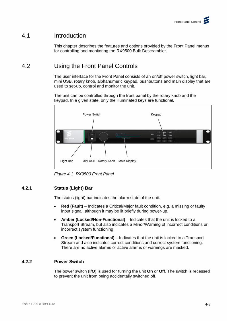
4.2 Using the Front Panel Controls The user interface for the Front Panel consists of an on/off power switch, light bar, mini USB, rotary knob, alphanumeric keypad, pushbuttons and main display that are used to set-up, control and monitor the unit.
The unit can be controlled through the front panel by the rotary knob and the keypad. In a given state, only the illuminated keys are functional.
Figure 4.1 RX9500 Front Panel
4.2.1 Status (Light) Bar
The status (light) bar indicates the alarm state of the unit.
• Red (Fault) – Indicates a Critical/Major fault condition, e.g. a missing or faulty input signal, although it may be lit briefly during power-up.
• Amber (Locked/Non-Functional) – Indicates that the unit is locked to a Transport Stream, but also indicates a Minor/Warning of incorrect conditions or incorrect system functioning.
• Green (Locked/Functional) – Indicates that the unit is locked to a Transport Stream and also indicates correct conditions and correct system functioning. There are no active alarms or active alarms or warnings are masked.
4.2.2 Power Switch
The power switch (I/O) is used for turning the unit On or Off. The switch is recessed to prevent the unit from being accidentally switched off.
Power Switch
Light Bar Mini USB Rotary Knob Main Display
Keypad
Front Panel Control
4-4 EN/LZT 790 0049/1 R4A
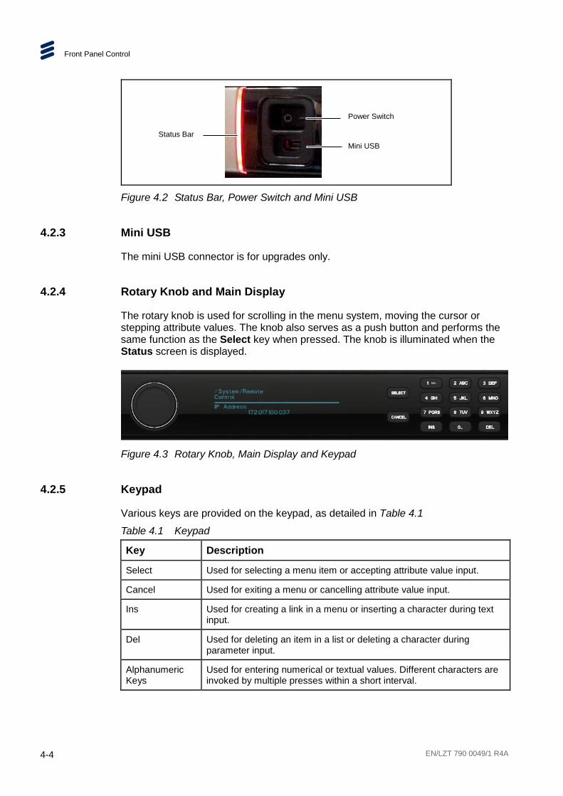
Figure 4.2 Status Bar, Power Switch and Mini USB
4.2.3 Mini USB
The mini USB connector is for upgrades only.
4.2.4 Rotary Knob and Main Display
The rotary knob is used for scrolling in the menu system, moving the cursor or stepping attribute values. The knob also serves as a push button and performs the same function as the Select key when pressed. The knob is illuminated when the Status screen is displayed.
Figure 4.3 Rotary Knob, Main Display and Keypad
4.2.5 Keypad
Various keys are provided on the keypad, as detailed in Table 4.1
Table 4.1 Keypad
Key Description
Select Used for selecting a menu item or accepting attribute value input.
Cancel Used for exiting a menu or cancelling attribute value input.
Ins Used for creating a link in a menu or inserting a character during text input.
Del Used for deleting an item in a list or deleting a character during parameter input.
Alphanumeric Keys
Used for entering numerical or textual values. Different characters are invoked by multiple presses within a short interval.
Power Switch
Status Bar Mini USB

Front Panel Control
EN/LZT 790 0049/1 R4A 4-5
4.3 Front Panel Menus The following menus, shown in Table 4.2 are available on the main screen.
To navigate to the next level of menus turn the rotary knob 1 click to the right. To return to the top level menu menus turn the rotary knob 1 click to the left. Press the rotary knob to make a selection.
Table 4.2 Front Panel Menus
Top Level Menu Menu Level 2 Menu Level 3 Menu Level 4 Description
IP address & Status
> /System > Remote Control > IP Address Sets IP parameters for Ethernet Control ports.
> Subnet Mask Sets Subnet mask parameters for Ethernet Control ports.
> Gateway Address Set Gateway parameters for Ethernet Control ports.
> Default MAC Address
Set default MAC address.
> Alarms > <critical> Lists currently active alarms beginning with critical alarms, then major, and minor.
> Versions > Hardware Version Displays the hardware version of the unit.
> Software Version Displays the software version of the unit.
> Assembly Date Displays the assembly date of the unit.
> Serial Number Displays the serial number of the unit.
> Chassis Identity Displays the chassis identity of the unit.
> Redundancy > State Displays the redundancy state of the unit.
> Restore Factory Defaults
> Erase All Settings?
Enables the erasure of all settings.
> Switch Boot Bank > Switch Boot Bank?
Enables switching of the boot bank.
Front Panel Control
4-6 EN/LZT 790 0049/1 R4A
4.4 Front Panel Menu Descriptions
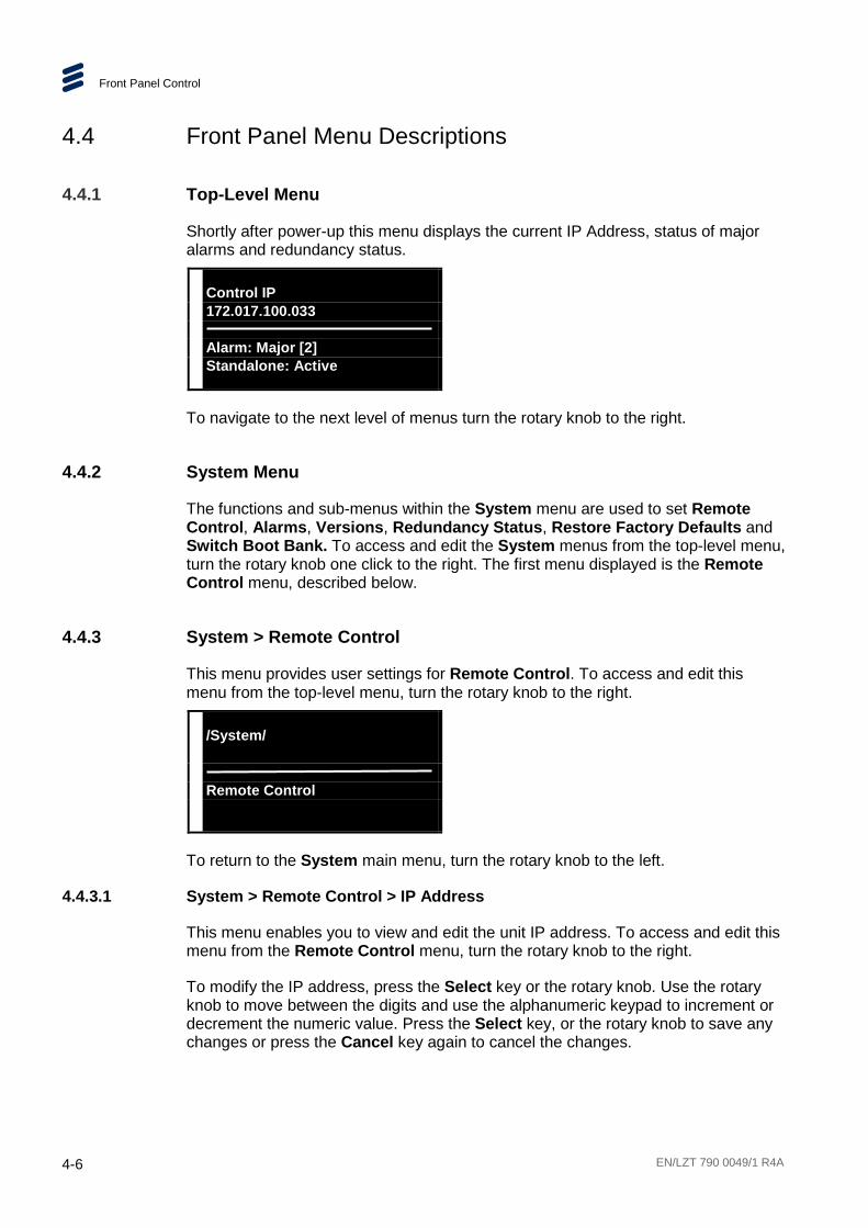
4.4.1 Top-Level Menu
Shortly after power-up this menu displays the current IP Address, status of major alarms and redundancy status.
Control IP 172.017.100.033 Alarm: Major [2] Standalone: Active
To navigate to the next level of menus turn the rotary knob to the right.
4.4.2 System Menu
The functions and sub-menus within the System menu are used to set Remote Control, Alarms, Versions, Redundancy Status, Restore Factory Defaults and Switch Boot Bank. To access and edit the System menus from the top-level menu, turn the rotary knob one click to the right. The first menu displayed is the Remote Control menu, described below.
4.4.3 System > Remote Control
This menu provides user settings for Remote Control. To access and edit this menu from the top-level menu, turn the rotary knob to the right.
/System/ Remote Control
To return to the System main menu, turn the rotary knob to the left.
4.4.3.1 System > Remote Control > IP Address
This menu enables you to view and edit the unit IP address. To access and edit this menu from the Remote Control menu, turn the rotary knob to the right.
To modify the IP address, press the Select key or the rotary knob. Use the rotary knob to move between the digits and use the alphanumeric keypad to increment or decrement the numeric value. Press the Select key, or the rotary knob to save any changes or press the Cancel key again to cancel the changes.

Front Panel Control
EN/LZT 790 0049/1 R4A 4-7
/System/Remote Control IP Address 172.017.100.037
4.4.3.2 System > Remote Control > Subnet Mask
This menu enables you to view and edit the subnet mask. To access and edit this menu from the IP Address menu, turn the rotary knob to the right.
To modify the subnet mask, press the Select key. Use the rotary knob to move between the digits and use the alphanumeric keypad to increment or decrement the numeric value. Press the Select key, or the rotary knob to save any changes or press the Cancel key again to cancel the changes.
/System/Remote Control Subnet Mask 255.255.000.000
4.4.3.3 System > Remote Control > Gateway Address
This menu enables you to view and edit the gateway address. To access and edit this menu from the Subnet Mask menu, turn the rotary knob to the right.
To modify the gateway address, press the Select key or the rotary knob. Use the rotary knob to move between the digits and use the alphanumeric keypad to increment or decrement the numeric value. Press the Select key, or the rotary knob to save any changes or press the Cancel key again to cancel the changes.
/System/Remote Control Gateway Address 172.017.254.254
4.4.3.4 System > Remote Control > Default MAC Address
This menu enables you to view and edit the default MAC address. To access and edit this menu from the Gateway Address menu, turn the rotary knob to the right.
To modify the default MAC address, press the Select key or the rotary knob. Use the rotary knob to move between the digits and use the alphanumeric keypad to increment or decrement the numeric value. Press the Select key, or the rotary knob, to save any changes or press the Cancel key again to cancel the changes.
Front Panel Control
4-8 EN/LZT 790 0049/1 R4A
/System/Remote Control Default MAC Address 00:20:AA:47:43:Bn
This is the last of the Remote sub-menus. Turn the rotary knob to the left to return to the System main menu.
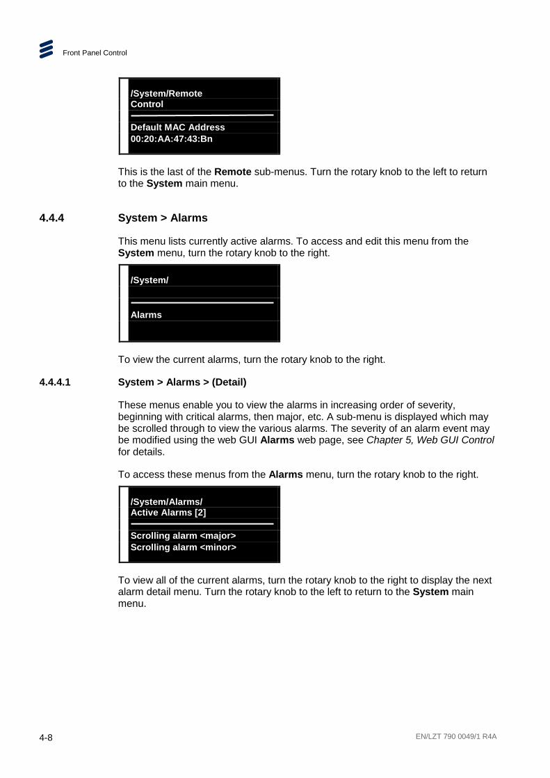
4.4.4 System > Alarms
This menu lists currently active alarms. To access and edit this menu from the System menu, turn the rotary knob to the right.
/System/ Alarms
To view the current alarms, turn the rotary knob to the right.
4.4.4.1 System > Alarms > (Detail)
These menus enable you to view the alarms in increasing order of severity, beginning with critical alarms, then major, etc. A sub-menu is displayed which may be scrolled through to view the various alarms. The severity of an alarm event may be modified using the web GUI Alarms web page, see Chapter 5, Web GUI Control for details.
To access these menus from the Alarms menu, turn the rotary knob to the right.
/System/Alarms/ Active Alarms [2] Scrolling alarm <major> Scrolling alarm <minor>
To view all of the current alarms, turn the rotary knob to the right to display the next alarm detail menu. Turn the rotary knob to the left to return to the System main menu.
Front Panel Control
EN/LZT 790 0049/1 R4A 4-9
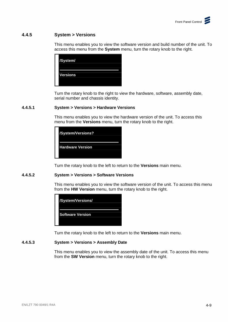
4.4.5 System > Versions
This menu enables you to view the software version and build number of the unit. To access this menu from the System menu, turn the rotary knob to the right.
/System/ Versions
Turn the rotary knob to the right to view the hardware, software, assembly date, serial number and chassis identity.
4.4.5.1 System > Versions > Hardware Versions
This menu enables you to view the hardware version of the unit. To access this menu from the Versions menu, turn the rotary knob to the right.
/System/Versions? Hardware Version 2.9
Turn the rotary knob to the left to return to the Versions main menu.
4.4.5.2 System > Versions > Software Versions
This menu enables you to view the software version of the unit. To access this menu from the HW Version menu, turn the rotary knob to the right.
/System/Versions/ Software Version X.X
Turn the rotary knob to the left to return to the Versions main menu.
4.4.5.3 System > Versions > Assembly Date
This menu enables you to view the assembly date of the unit. To access this menu from the SW Version menu, turn the rotary knob to the right.

Front Panel Control
4-10 EN/LZT 790 0049/1 R4A
/System/Versions/ Assembly Date Tue Aug 13 09:10:51 UTC 2013
Turn the rotary knob to the left to return to the Versions main menu.
4.4.5.4 System > Versions > Serial Number
This menu enables you to view the serial number of the unit. To access this menu from the Assembly Date menu, turn the rotary knob to the right.
/System/Versions/ Serial Number 17341
Turn the rotary knob to the left to return to the Versions main menu.
4.4.5.5 System > Versions > Chassis Identity
This menu enables you to view the chassis identity of the unit. To access this menu from the Serial Number menu, turn the rotary knob to the right.
/System/Versions/ Chassis Identity AXXXXXXXXXXXXX
Turn the rotary knob to the left to return to the System main menu.
4.4.6 System > Redundancy
This menu enables you to view the redundancy state of the unit. To access and edit this menu from the System menu, turn the rotary knob to the right.
/System/ Redundancy
Press the Select key or the rotary knob to view the redundancy status.
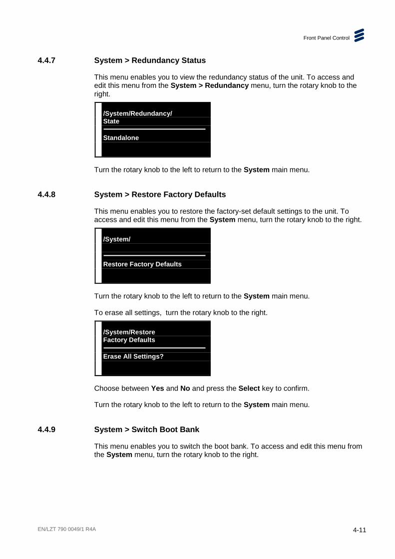
Front Panel Control
EN/LZT 790 0049/1 R4A 4-11
4.4.7 System > Redundancy Status
This menu enables you to view the redundancy status of the unit. To access and edit this menu from the System > Redundancy menu, turn the rotary knob to the right.
/System/Redundancy/ State Standalone
Turn the rotary knob to the left to return to the System main menu.
4.4.8 System > Restore Factory Defaults
This menu enables you to restore the factory-set default settings to the unit. To access and edit this menu from the System menu, turn the rotary knob to the right.
/System/ Restore Factory Defaults
Turn the rotary knob to the left to return to the System main menu.
To erase all settings, turn the rotary knob to the right.
/System/Restore Factory Defaults Erase All Settings? No
Choose between Yes and No and press the Select key to confirm.
Turn the rotary knob to the left to return to the System main menu.
4.4.9 System > Switch Boot Bank
This menu enables you to switch the boot bank. To access and edit this menu from the System menu, turn the rotary knob to the right.

Front Panel Control
4-12 EN/LZT 790 0049/1 R4A
/System/ Switch Boot Bank
To switch the boot bank turn the rotary knob to the Right.
/System/Switch Boot Bank Switch Boot Bank? No
Choose between Yes and No and press the Select key to confirm.
Turn the rotary knob to the left to return to the System main menu.

EN/LZT 790 0049/1 R4A 5-1
5 Web GUI Control Chapter 5
Contents 5.1 Using the Web Graphical User Interface .............................................. 5-5 5.1.1 Pages (Navigation Header) ................................................................. 5-5 5.1.2 Tabs (Navigation Header).................................................................... 5-6 5.1.3 Apply/Discard Buttons ......................................................................... 5-6 5.1.4 Widgets ............................................................................................... 5-7 5.1.5 Accordion Panels ................................................................................ 5-8 5.1.6 Supported Actions and Features ......................................................... 5-8 5.2 Dashboard Page ................................................................................. 5-9 5.2.1 Demodulation Status Widget ............................................................... 5-9 5.2.2 Alarms Widget ................................................................................... 5-10 5.2.2.1 Active Alarms .................................................................................... 5-10 5.2.2.2 Alarm History ..................................................................................... 5-10 5.2.3 Inputs Widget .................................................................................... 5-11 5.3 Services Page ................................................................................... 5-11 5.3.1 Alarm Newsfeed ................................................................................ 5-12 5.3.2 Inputs Widget .................................................................................... 5-13 5.3.3 Outputs Widget .................................................................................. 5-14 5.3.4 Properties Widget .............................................................................. 5-15 5.3.4.1 Properties (Input - Card) .................................................................... 5-15 5.3.4.2 Properties (Input – IP) ....................................................................... 5-17 5.3.4.3 Properties (Input - Transport Stream) ................................................ 5-18 5.3.4.4 Properties (Input - Service) ................................................................ 5-18 5.3.4.5 Properties (Input - Video Component) ............................................... 5-18 5.3.4.6 Properties (Input - Audio Component) ............................................... 5-19 5.3.4.7 Properties (Output - Transport Stream) ............................................. 5-20 5.3.4.8 Properties (Output - Service) ............................................................. 5-22 5.3.4.9 Properties (Output - Video Component) ............................................. 5-22 5.3.4.10 Properties (Output - Audio Component) ............................................. 5-23 5.4 Device Page ...................................................................................... 5-23 5.4.1 Hardware Tab .................................................................................... 5-23 5.4.1.1 Hardware View Widget ...................................................................... 5-24 5.4.1.2 Device Items Widget .......................................................................... 5-24 5.4.1.3 Properties Widget .............................................................................. 5-25 5.4.2 Network Tab ...................................................................................... 5-27 5.4.2.1 Network Interfaces Widget ................................................................. 5-27 5.4.2.2 Properties Widget .............................................................................. 5-28 5.4.3 SNMP Tab ......................................................................................... 5-29

Web GUI Control
5-2 EN/LZT 790 0049/1 R4A
5.4.3.1 SNMP Properties Widget .................................................................. 5-29 5.4.4 Licenses Tab .................................................................................... 5-30 5.4.4.1 Install License Widget ....................................................................... 5-30 5.4.4.2 Licenses Widget ................................................................................ 5-31 5.5 Monitoring Page ................................................................................ 5-31 5.5.1 Alarms Tab ....................................................................................... 5-32 5.5.1.1 Active Alarms .................................................................................... 5-32 5.5.1.2 Alarm History Panel .......................................................................... 5-33 5.5.2 Alarm Overrides Tab ......................................................................... 5-33 5.6 Support Page .................................................................................... 5-35 5.6.1 Import and Export Tab ...................................................................... 5-35 5.6.1.1 Import Widget ................................................................................... 5-35 5.6.1.2 Export Widget ................................................................................... 5-36 5.6.2 Log Files Tab .................................................................................... 5-36
List of Figures Figure 5.1 Web GUI Components (Typical Page) .............................................. 5-5 Figure 5.2 Web Pages ....................................................................................... 5-6 Figure 5.3 Tab Pages ........................................................................................ 5-6 Figure 5.4 Apply/Discard Buttons ...................................................................... 5-6 Figure 5.5 Widgets (Example) ........................................................................... 5-7 Figure 5.6 Selecting and Sorting Tabular Data .................................................. 5-7 Figure 5.7 Accordion Panel (Example) .............................................................. 5-8 Figure 5.8 Dashboard Page ............................................................................... 5-9 Figure 5.9 Demodulation Status Widget............................................................. 5-9 Figure 5.10 Alarms Widget - Active Alarms ........................................................ 5-10 Figure 5.11 Alarms Widget - Alarm History ........................................................ 5-11 Figure 5.12 Inputs Widget .................................................................................. 5-11 Figure 5.13 Services Page ................................................................................ 5-12 Figure 5.14 Alarm Newsfeed (Minimized) .......................................................... 5-12 Figure 5.15 Alarm Newsfeed (Expanded) .......................................................... 5-13 Figure 5.16 Inputs Widget .................................................................................. 5-14 Figure 5.17 Outputs Widget ............................................................................... 5-14 Figure 5.18 Properties (Input - Card) ................................................................. 5-15 Figure 5.19 Properties (Input - IP) ..................................................................... 5-17 Figure 5.20 Properties (Input - Transport Stream) ............................................. 5-18 Figure 5.21 Properties (Input - Service) ............................................................. 5-18 Figure 5.22 Properties (Input - Video Component) ............................................. 5-19 Figure 5.23 Properties (Input - Audio Component) ............................................. 5-19 Figure 5.24 Properties (Output - Transport Stream) ........................................... 5-20 Figure 5.25 Properties (Output - Service) .......................................................... 5-22 Figure 5.26 Properties (Output - Video Component) .......................................... 5-22 Figure 5.27 Properties (Output - Audio Component) .......................................... 5-23 Figure 5.28 Device Page > Hardware Tab ......................................................... 5-24 Figure 5.29 Hardware View Widget ................................................................... 5-24 Figure 5.30 Device Items Widget ....................................................................... 5-25 Figure 5.31 Hardware Properties (Card) ............................................................ 5-25 Figure 5.32 Device Page > Network Tab ........................................................... 5-27 Figure 5.33 Network Interfaces Widget .............................................................. 5-27

Web GUI Control
EN/LZT 790 0049/1 R4A 5-3
Figure 5.34 Device Properties (Data Interface Group)........................................ 5-28 Figure 5.35 Device Page > SNMP Tab .............................................................. 5-29 Figure 5.36 Device Page > Licenses Tab ........................................................... 5-30 Figure 5.37 Install Licenses Widget .................................................................... 5-30 Figure 5.38 Licenses Widget .............................................................................. 5-31 Figure 5.39 Monitoring Page > Alarms Tab ........................................................ 5-32 Figure 5.40 Active Alarms Panel ........................................................................ 5-32 Figure 5.41 Alarms History Panel ....................................................................... 5-33 Figure 5.42 Monitoring Page > Alarm Overrides Tab ......................................... 5-34 Figure 5.43 Overridden Severity Menu ............................................................... 5-34 Figure 5.44 Overridden Alarms Filter ................................................................. 5-34 Figure 5.45 Support Page > Import and Export Tab .......................................... 5-35 Figure 5.46 Import Widget .................................................................................. 5-36 Figure 5.47 Export Widget ................................................................................. 5-36 Figure 5.48 Support Page > Log Files Tab ........................................................ 5-37
List of Tables Table 5.1 Alarm Newsfeed Control Icons ........................................................ 5-13

Web GUI Control
5-4 EN/LZT 790 0049/1 R4A
BLANK

Web GUI Control
EN/LZT 790 0049/1 R4A 5-5
5.1 Using the Web Graphical User Interface The RX9500 Bulk Descrambler is designed to be configured and controlled by its own web graphical user interface (GUI). This chapter describes, in sequence, all the GUI screens, and their functions, associated with the Host Card and base chassis.
The GUI uses widget-based architecture. This section defines the terminology used to describe typical elements of the GUI screens and any general operations that may be performed.
Note: For GUI screens and functions associated with Option Cards, see the relevant Option Card Reference Guide.
The main components of a typical Web GUI page are shown in Figure 5.1.
Figure 5.1 Web GUI Components (Typical Page)
5.1.1 Pages (Navigation Header)
The control functions for the unit are grouped into six main categories. The control parameters for each category are presented on a separate web page. Links to these web pages is provided at the top of the header above the unit number. Simply click on them to access the relevant web page.
Pages
Widgets
Tabs
Accordion Panel
Apply/Discard Buttons

Web GUI Control
5-6 EN/LZT 790 0049/1 R4A
Figure 5.2 Web Pages
The main web pages are:
• Dashboard (see section 5.2 for details)
• Services (see section 5.3 for details)
• Device (see section 5.4 for details)
• Monitoring (see section 5.5 for details)
• Support (see section 5.6 for details)
5.1.2 Tabs (Navigation Header)
Where appropriate, control functions may be further broken down into smaller sub-categories with each sub-category presented on a separate ‘tab’ page. Links to these tab pages are provided at the bottom of the header below the unit banner (unit number). Simply click on them to access the relevant tab page.
Figure 5.3 Tab Pages
5.1.3 Apply/Discard Buttons
Changes made to parameters on any of the GUI pages/tabs are automatically highlighted in orange, signifying that these changes have not yet been saved. If you modify parameters and then attempt to navigate away from the page/tab, a warning dialog will be displayed.
Figure 5.4 Apply/Discard Buttons
The two buttons on the right-hand side of the web GUI header are:

Web GUI Control
EN/LZT 790 0049/1 R4A 5-7
• Apply – Enables any changes made to that page/tab to be applied. The affected parameters will then become part of the current unit configuration and their color will return to normal, i.e. black.
• Discard – Enables any changes made to that page/tab to be rejected. The unit configuration will not be modified.
5.1.4 Widgets
Widgets are sub-divisions of pages and tabs (with a blue title bar). They allow you to select or modify settings and parameters or display relevant information. Widgets may be resized by dragging the splitters between them, if available.
Figure 5.5 Widgets (Example)
Where relevant, objects may be copied by drag-and-drop within or between widgets.
Selecting and Sorting Tabular Data
Tables are frequently used within widgets to present data. The data in all tables may be alphabetically sorted ascending descending by clicking on the black table column header and selecting the appropriate option from the drop-down menu.
Figure 5.6 Selecting and Sorting Tabular Data
In addition, columns may be selected or deselected for viewing by clicking on the black table column header and selecting the appropriate option from the drop-down menu by checking or unchecking the relevant checkbox.

Web GUI Control
5-8 EN/LZT 790 0049/1 R4A
5.1.5 Accordion Panels
Accordion panels are further sub-divisions of widgets (with a gray title bar). They are separate areas that may be collapsed and expanded, to show more or less information, by clicking on the small arrow on the top left hand of the panel.
Figure 5.7 Accordion Panel (Example)
5.1.6 Supported Actions and Features
The following actions and features are supported by the web GUI:
• Drag-and-Drop – The web GUI supports drag-and-drop, for example in the Services > Configure page, to enables you to quickly copy services from the Inputs to the Outputs widget. Additionally, when selecting services, the web GUI supports Shift-Click operation to enables you to select multiple adjacent items, and Ctrl-Click operation when selecting multiple non-adjacent items.
• Drop-Down Menus – Some web GUI pages provide drop-down menus to enables you to select from the available options.
• Right-Click/Context Menus – Some web GUI pages provide right-click menus for speedier configuration.
• Parameter Highlighting – When you modify service and profile properties, any changes you make will be highlighted as orange text. These changes will not be carried out until they are confirmed, by clicking the Apply button.
• Web Page Resizing and Collapsing – To enable you to view just the information that you need, the panes displayed on some web pages may be resized by dragging the pane boundary. If your monitor screen width is less than 1300 pixels, panes may be collapsed automatically.
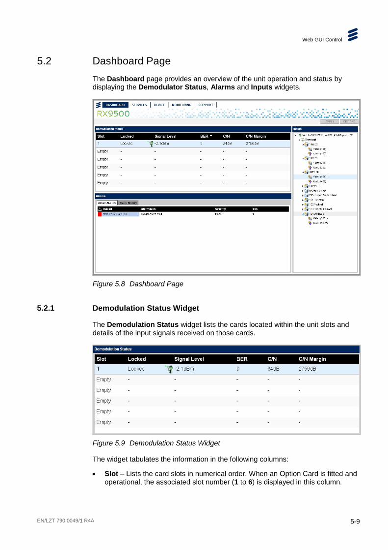
Web GUI Control
EN/LZT 790 0049/1 R4A 5-9
5.2 Dashboard Page The Dashboard page provides an overview of the unit operation and status by displaying the Demodulator Status, Alarms and Inputs widgets.
Figure 5.8 Dashboard Page
5.2.1 Demodulation Status Widget
The Demodulation Status widget lists the cards located within the unit slots and details of the input signals received on those cards.
Figure 5.9 Demodulation Status Widget
The widget tabulates the information in the following columns:
• Slot – Lists the card slots in numerical order. When an Option Card is fitted and operational, the associated slot number (1 to 6) is displayed in this column.

Web GUI Control
5-10 EN/LZT 790 0049/1 R4A
Details of the input signal received on each card are displayed in the associated columns. If a card slot is not occupied, or if the card is of the wrong type, it will display as Empty. See Chapter 1, Introduction for a rear panel diagram showing the slot positions.
• Locked – Indicates whether the unit has achieved carrier lock with the received RF input signal (Locked / Not Locked).
• Signal Level – Displays the signal level (in dBm) of the received RF input signal.
• BER – Displays the Bit Error Rate (or Ratio) detected on the received RF input signal. Indicates the number of data bits errors received due to noise, interference, distortion or synchronization error.
• C/N – Displays the Carrier-to-Noise level (in dB) of the received RF input signal. Indicates the strength of the received carrier signal.
• C/N Margin – Displays the Carrier-to-Noise Margin (in dB) detected on the received RF input signal.
5.2.2 Alarms Widget
The Alarms widget provides status information about the various alarms fitted to the unit. It can be used to view Active Alarms or Alarm History.
Note: The Alarms widget is also displayed on the Monitoring > Alarms page. See section 5.5.1 for a full description of this widget.
5.2.2.1 Active Alarms
All current active alarms are listed in this widget, including information about the date and time the alarm was raised, an alarm description, the severity of the alarm (critical, major or minor) and which card slots are affected by it.
Figure 5.10 Alarms Widget - Active Alarms
Note: The Alarms widget is also displayed on the Monitoring > Alarms page. See section 5.5.1 for a full description of this widget.
5.2.2.2 Alarm History
A detailed record of previous alarms are listed in this widget, including the date and time the alarm was raised and cleared, an alarm description, the severity of the alarm (critical, major or minor) and which card slots are affected by it.

Web GUI Control
EN/LZT 790 0049/1 R4A 5-11
Figure 5.11 Alarms Widget - Alarm History
Note: The Alarms widget is also displayed on the Monitoring > Alarms page. See section 5.5.1 for a full description of this widget.
5.2.3 Inputs Widget
The Inputs widget displays a list of Cards fitted to the unit, the incoming Transport Streams, the Services and their Components. Click on the triangle alongside each item in the displayed tree structure to expand or collapse to reveal or hide further information.
Figure 5.12 Inputs Widget
Note: The Inputs widget is also displayed on the Services > Configure page. See section 5.3.2 for a full description of this widget.
5.3 Services Page The Services page provides status and properties details of Cards, Transport Streams, Services and Components (video and audio). Only one tab (Configure) is provided and is automatically selected.

Web GUI Control
5-12 EN/LZT 790 0049/1 R4A
Figure 5.13 Services Page
5.3.1 Alarm Newsfeed
The Services page has an Alarm Newsfeed located above the widgets. This panel notifies you of incoming active alarms and/or alerts.
Figure 5.14 Alarm Newsfeed (Minimized)
New alarm messages (at the left-hand side) scroll automatically through the 1-line display and comprise a colored warning symbol, indicating the severity of the alarm, followed by the month, date, year, time (hh:mm:ss) and then an alarm description. Alarm colors are:
• Red – critical error condition.
• Dark Orange – major warning condition.
• Light Orange – minor warning condition.
Warning Symbol
Date
Description Number of Active Alarms
Mark as Read
Play/ Pause
Backward/ Forward
Expand/ Collapse

Web GUI Control
EN/LZT 790 0049/1 R4A 5-13
• Yellow – warning messages.
Alarm message controls are provided on the right-hand side of the Alarm Newsfeed as detailed in Table 5.1. Grayed-out icons are non-functional.
Table 5.1 Alarm Newsfeed Control Icons
Control Description
Displays the number of active alarms and/or alerts. Click on the down-arrow to acknowledge the alarm/alert message and Mark as Read
Pauses or plays the Alarm Newsfeed .
Skips backward or forward through the list of active alarms.
Expands or collapses the list of active alarms.
The Alarm Newsfeed can be expanded to display the list of all current active alarms by selecting the down-arrow at the right-hand side.
Figure 5.15 Alarm Newsfeed (Expanded)
5.3.2 Inputs Widget
The Inputs widget displays a list of Cards fitted to the unit, the incoming Transport Streams, the Services and their Components (video and audio). Click on the triangle alongside each item in the displayed tree structure to expand or collapse to reveal or hide further information.
The plus icon enables new Transport Streams to be added to the Inputs list when IP inputs are available.
The wastebasket icon enables selected Transport Stream to be deleted from the Inputs list. A confirmation dialog will be displayed.
See Chapter 3, Getting Started for details of adding and deleting Transport Streams and Services.

Web GUI Control
5-14 EN/LZT 790 0049/1 R4A
Figure 5.16 Inputs Widget
Note: The Inputs widget is also available on the Dashboard page.
5.3.3 Outputs Widget
The Outputs widget lists the output Transport Streams that have been selected, the Services contained within those streams and the Components (video and audio). Click on the triangle alongside each item in the displayed tree structure to expand or collapse to reveal or hide further information.
Figure 5.17 Outputs Widget
The plus icon enables new Transport Streams to be added to the list.
The wastebasket icon enables selected Transport Stream to be deleted from the list. A confirmation dialog will be displayed.
See Chapter 3, Getting Started for details of adding and deleting Transport Streams and Services.

Web GUI Control
EN/LZT 790 0049/1 R4A 5-15
5.3.4 Properties Widget
The Properties widget displays parameters and information that are relevant for the item selected in either the Inputs or Outputs widget.
5.3.4.1 Properties (Input - Card)
The following parameters are displayed in the Properties widget when a Card is selected in the Inputs widget.
Figure 5.18 Properties (Input - Card)
The following fields are available on this widget:
Status
• Input Locked – Indicates (in green) to confirm that the unit is phase-locked to the received RF Carrier signal . Displays Not locked (in red) when an input is not detected.

Web GUI Control
5-16 EN/LZT 790 0049/1 R4A
• C/N Ratio – Displays the Carrier-to-Noise ratio (in dB) of the received RF input.
• Signal Level – Indicates the signal level (in dBm) of the received RF input.
• BER – Displays the Bit Error Rate of the input signal. This should be zero if the connection and the data are good.
• Modulation Type – Displays the type of modulation (e.g. QPSK) detected on the received RF input signal.
• Demodulation Standard – Displays the demodulation standard (e.g. DVB-S, DVB-S2) used on the received RF input signal.
• FEC Rate – Displays the Forward Error Correction Rate used on the RF input signal.
• Spectrum Sense – Displays the Spectrum Sense (e.g. Inverted) used on the RF input signal.
Tuning Properties
• LNB LO Frequency – Sets the Low Noise Block Local Oscillator Frequency (in MHz) for the expected RF input signal. Increment or decrement using the arrow buttons.
• Satellite Frequency – Sets the Satellite Frequency (in MHz) for the expected RF input signal. Increment or decrement using the arrow buttons.
• Symbol Rate – Sets the Symbol Rate (in MSym/s) for the expected RF input signal. Increment or decrement using the arrow buttons.
• Modulation – Sets the modulation type for the expected RF input signal. Select an option from the drop-down menu.
• Roll-Off – Sets the Percentage of roll-off for the expected RF input signal. Select an option from the drop-down menu.
• Spectrum Sense – Sets the Spectrum Sense for the expected RF input signal. Select an option from the drop-down menu.

Web GUI Control
EN/LZT 790 0049/1 R4A 5-17
• Search Range – Sets the range of frequencies (in Hz) for the searching for the RF input signal.
• LNB Power – Sets the Low Noise Block power supply. Select from the drop-down menu.
• LNB 22 kHz (Hi-Band) – Enables or disables a 22 kHz reference signal for th Low Noise Block. Place a check in the checkbox to enable.
5.3.4.2 Properties (Input – IP)
The following parameters are displayed in the Properties widget when an IP Input Transport Stream is selected in the Inputs widget.
Figure 5.19 Properties (Input - IP)
Source
• Data Interface – Selects which interface connector (Ge1 or Ge2) is used.
• Multicast IP Address – Sets the Multicast IP address. Type the IP address directly into the field.
• Source Specific IP Address – Sets the Source Specific IP address. Type the IP address directly into the field.
• UDP Port – Sets the destination User Datagram Protocol port number. Increment or decrement using the arrow buttons (valid range = 0 - 65535).
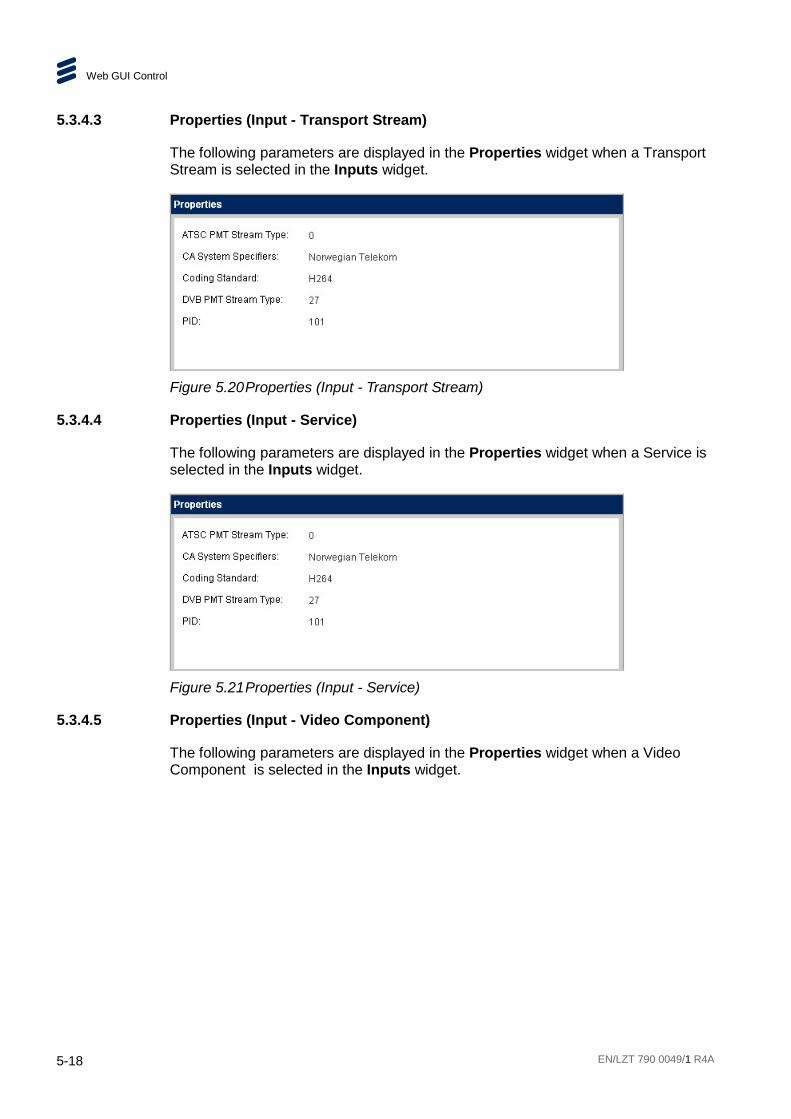
Web GUI Control
5-18 EN/LZT 790 0049/1 R4A
5.3.4.3 Properties (Input - Transport Stream)
The following parameters are displayed in the Properties widget when a Transport Stream is selected in the Inputs widget.
Figure 5.20 Properties (Input - Transport Stream)
5.3.4.4 Properties (Input - Service)
The following parameters are displayed in the Properties widget when a Service is selected in the Inputs widget.
Figure 5.21 Properties (Input - Service)
5.3.4.5 Properties (Input - Video Component)
The following parameters are displayed in the Properties widget when a Video Component is selected in the Inputs widget.
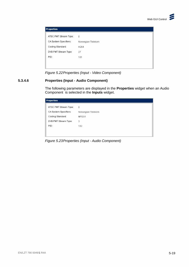
Web GUI Control
EN/LZT 790 0049/1 R4A 5-19
Figure 5.22 Properties (Input - Video Component)
5.3.4.6 Properties (Input - Audio Component)
The following parameters are displayed in the Properties widget when an Audio Component is selected in the Inputs widget.
Figure 5.23 Properties (Input - Audio Component)
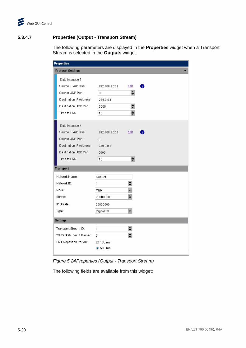
Web GUI Control
5-20 EN/LZT 790 0049/1 R4A
5.3.4.7 Properties (Output - Transport Stream)
The following parameters are displayed in the Properties widget when a Transport Stream is selected in the Outputs widget.
Figure 5.24 Properties (Output - Transport Stream)
The following fields are available from this widget:

Web GUI Control
EN/LZT 790 0049/1 R4A 5-21
Protocol Settings
The following fields are available for both Data Interface 3 and 4.
• Source IP Address – Displays the source IP address, which can be edited by selecting the Edit button which will take you to the Device page (see Figure 5.32). Selecting the Info button displays the dialog box shown below.
• Source UDP Port – Sets the source User Datagram Protocol port number. Increment or decrement using the arrow buttons (valid range = 0 - 65535).
• Destination IP Address – Sets the destination IP address. Type the IP address directly into the field.
• Destination UDP Port – Sets the destination User Datagram Protocol port number. Increment or decrement using the arrow buttons (valid range = 0 - 65535).
• Time to Live – Defines the time (in seconds) after which a packet is to be discarded. TTL is decremented at least by one each time a packet goes through a router or switch and if it reaches zero the packet is discarded. Increment or decrement using the arrow buttons (valid range = 1 - 240).
Transport
• Network Name – Sets the name of the network for the Transport Stream. Type directly into the field.
• Network ID – Sets the Network Identifier for the Transport Stream. Increment or decrement using the arrow buttons.
• Mode – Sets the transport mode (e.g. CBR, VBR) for the Transport Stream. Select from the drop-down menu.
• Bit rate – Sets the bit rate (in bps) of the Transport Stream. Increment or decrement using the arrow buttons (valid range = 0.01 - 216 Mbps).
• IP Bit rate – Displays the Interface Protocol bit rate. This is related to the “Bit rate” but includes the overhead for IP headers.
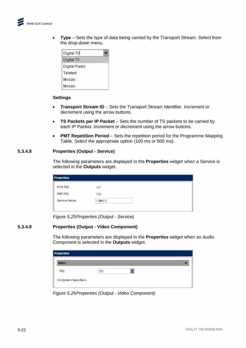
Web GUI Control
5-22 EN/LZT 790 0049/1 R4A
• Type – Sets the type of data being carried by the Transport Stream. Select from the drop-down menu.
Settings
• Transport Stream ID – Sets the Transport Stream Identifier. Increment or decrement using the arrow buttons.
• TS Packets per IP Packet – Sets the number of TS packets to be carried by each IP Packet. Increment or decrement using the arrow buttons.
• PMT Repetition Period – Sets the repetition period for the Programme Mapping Table. Select the appropriate option (100 ms or 500 ms).
5.3.4.8 Properties (Output - Service)
The following parameters are displayed in the Properties widget when a Service is selected in the Outputs widget.
Figure 5.25 Properties (Output - Service)
5.3.4.9 Properties (Output - Video Component)
The following parameters are displayed in the Properties widget when an Audio Component is selected in the Outputs widget.
Figure 5.26 Properties (Output - Video Component)

Web GUI Control
EN/LZT 790 0049/1 R4A 5-23
5.3.4.10 Properties (Output - Audio Component)
The following parameters are displayed in the Properties widget when an Audio Component is selected in the Outputs widget.
Figure 5.27 Properties (Output - Audio Component)
5.4 Device Page The Device page provides access to status and properties details for various aspects of the unit. Several tabs are provided:
• Hardware
• Network
• SNMP
• Licenses
5.4.1 Hardware Tab
The Hardware tab provides access to details of option card location and properties.

Web GUI Control
5-24 EN/LZT 790 0049/1 R4A
Figure 5.28 Device Page > Hardware Tab
5.4.1.1 Hardware View Widget
The Hardware View widget displays a pictorial representation of which option cards are fitted within the unit. When cards are selected in the Device Items widget, the appropriate card is highlighted in the Hardware View.
Figure 5.29 Hardware View Widget
5.4.1.2 Device Items Widget
This widget displays a list of the available Card Slots, in the unit. When a particular slot is selected, the properties of the card, fitted in that slot, are displayed in the Properties widget.
Slot 0 corresponds to the unit Host Card.
Slots 1 - 6 correspond to the Option Cards that may be fitted to the rear panel of the unit.

Web GUI Control
EN/LZT 790 0049/1 R4A 5-25
Figure 5.30 Device Items Widget
5.4.1.3 Properties Widget
The Properties widget displays the properties of the Card selected in the Device Items widget
Figure 5.31 Hardware Properties (Card)

Web GUI Control
5-26 EN/LZT 790 0049/1 R4A
The following fields are available from this page:
• Installed – This checkbox, when checked, indicates that the Card listed is installed and booted in the slot.
• Slot – Indicates which slot the Card is installed in.
• Name – Displays the Card name, automatically detected by the system.
• Product Number (S Number) – Displays the Product S number.
• Package Version – Displays the version number of this package.
• Package Valid – This checkbox, when checked, indicates that the package is valid and all individual versions are valid for this unit.
• Hardware Modification Version – Displays the modification status of the hardware.
• Serial Number – Displays the Card serial number.
CAM Modules
• CAM 1 – Indicates whether a CAM is installed in the Card CAM1 slot (Installed or Empty).
• Reboot CAM – This button enables you to manually reboot the CAM. A confirmation dialog will be displayed.
• CA Type – Displays the Conditional Access type of the CAM.
• Expiry Date – Displays the Expiry Date of the CAM, if applicable. Otherwise, Not set is displayed.
• PID Capability – Displays information about Packet Identifier Capability. Otherwise, undefined PIDs is displayed.
• Automatic CAM Reboot – This checkbox enables you to reboot the CAM automatically in the event of …..?
• CAM 2 – Indicates whether a CAM is installed in the Card CAM2 slot (Installed or Empty).

Web GUI Control
EN/LZT 790 0049/1 R4A 5-27
5.4.2 Network Tab
The Network tab displays the network interfaces of the unit and their properties.
Figure 5.32 Device Page > Network Tab
5.4.2.1 Network Interfaces Widget
The Network Interfaces widget lists the network interfaces (data interface groups) provided by the unit. When selected, by clicking on them, their associated properties are displayed in the Properties widget.
Figure 5.33 Network Interfaces Widget

Web GUI Control
5-28 EN/LZT 790 0049/1 R4A
5.4.2.2 Properties Widget
The Properties widget displays the properties of the items selected in the Network Interfaces widget.
Figure 5.34 Device Properties (Data Interface Group)
The following fields are available from this page:
• Name – Displays the name assigned to Data Interface Group.
• Redundancy Mode – Displays the redundancy mode of the Data Interface group. An Information button is provided next to this field which, when selected, gives details of the various Redundancy Mode options.
Data Interface 3/4
Data Interface 3 and 4 are similar and provide the following properties.
• Port Type – Displays the type of port used for this interface.
• Link Status – Indicates whether the interface link is active (Link Up) or not. Also displays the associated communications speed (in Gbps).
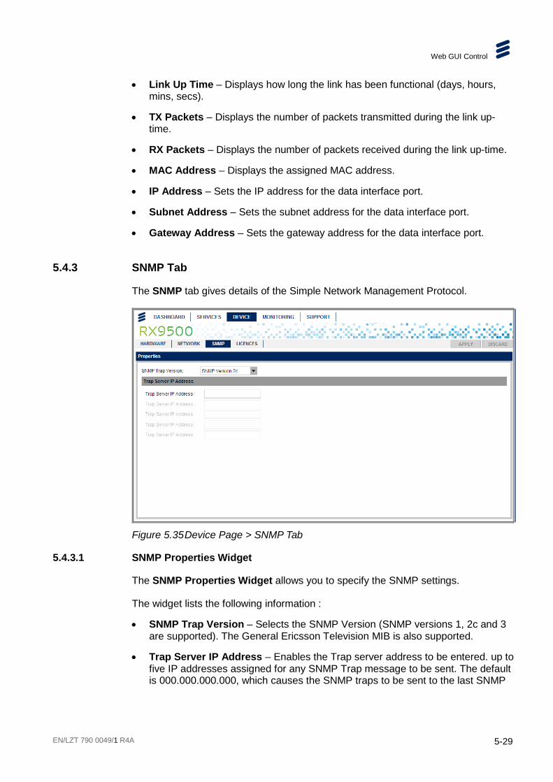
Web GUI Control
EN/LZT 790 0049/1 R4A 5-29
• Link Up Time – Displays how long the link has been functional (days, hours, mins, secs).
• TX Packets – Displays the number of packets transmitted during the link up-time.
• RX Packets – Displays the number of packets received during the link up-time.
• MAC Address – Displays the assigned MAC address.
• IP Address – Sets the IP address for the data interface port.
• Subnet Address – Sets the subnet address for the data interface port.
• Gateway Address – Sets the gateway address for the data interface port.
5.4.3 SNMP Tab
The SNMP tab gives details of the Simple Network Management Protocol.
Figure 5.35 Device Page > SNMP Tab
5.4.3.1 SNMP Properties Widget
The SNMP Properties Widget allows you to specify the SNMP settings.
The widget lists the following information :
• SNMP Trap Version – Selects the SNMP Version (SNMP versions 1, 2c and 3 are supported). The General Ericsson Television MIB is also supported.
• Trap Server IP Address – Enables the Trap server address to be entered. up to five IP addresses assigned for any SNMP Trap message to be sent. The default is 000.000.000.000, which causes the SNMP traps to be sent to the last SNMP

Web GUI Control
5-30 EN/LZT 790 0049/1 R4A
master. See Chapter 6, Bulk Descrambling and Networking for further information.
5.4.4 Licenses Tab
The Licenses tab allows the user to upload licenses to the unit and also gives details of licenses already installed.
Figure 5.36 Device Page > Licenses Tab
5.4.4.1 Install License Widget
The Install License Widget allows you to upload new licenses as required. See Chapter 3, Getting Started for details of how to install licenses.
Figure 5.37 Install Licenses Widget

Web GUI Control
EN/LZT 790 0049/1 R4A 5-31
5.4.4.2 Licenses Widget
The Licenses widget displays details of all installed licenses, including whether licenses have expired or active.
Figure 5.38 Licenses Widget
The widget tabulates the information in the following columns:
• Description – Displays a text description of the license.
• Order Code – Displays the Ericsson order code.
• Feature ID – Details any restrictions on use of the license.
• Instances – Details the number of instances of the license that are installed on the unit.
• Duration – Displays the number of days duration remaining for a time-limited license, if applicable, before it expires.
• Remaining – When a time-limited license is supplied, the remaining time is decremented every minute that the feature id in use. When the feature is not in use/not applicable, the remaining time stops decrementing. When the remaining time runs out, this feature is disabled/not accessible and displays Expired.
• Grace – When a dual counter license is supplied (for situations where a unit is used as an occasional backup), the Grace timer is decremented every minute that the feature is used, when the licensed feature is initially enabled. If the Grace period timer expires then the Remaining timer is decremented. If the license is released (i.e. the feature is not in use) then the Grace counter is reset to its initial value, allowing the re-use of the grace period. However, if the feature continues to be used and the remaining timer runs out, the feature is disabled / not accessible.
• Expired – Indicates (when checked) that a time-limited license has expired.
• Active – Indicates (when checked) that an instance of the license exists and is in use.
5.5 Monitoring Page The Monitoring page provides facilities for monitoring and configuring unit alarms. Two tabs are provided:
• Alarms
• Alarm Overrides

Web GUI Control
5-32 EN/LZT 790 0049/1 R4A
5.5.1 Alarms Tab
The Alarms widget provides status information about the various alarms fitted to the unit. It can be used to view Active Alarms or Alarm History.
Figure 5.39 Monitoring Page > Alarms Tab
5.5.1.1 Active Alarms
All current active alarms are listed, including information about the date and time the alarm was raised, an alarm description, the severity of the alarm and which card slots are affected by it.
Note: The Alarms widget is also available on the Monitoring > Alarms page.
Figure 5.40 Active Alarms Panel
The panel tabulates information in the following columns:
• Symbol – Displays a colored symbol identifying the severity of the alarm message:
- Red – Critical alarm.
- Dark Orange – Major alarm.
- Light Orange – Minor alarm.
- Yellow – Warning message.
- Green – Information message.
• Raised – Displays the month, day, year, and time (hh:mm:ss) that the alarm was detected.
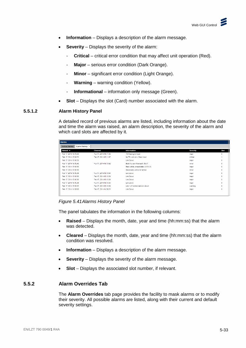
Web GUI Control
EN/LZT 790 0049/1 R4A 5-33
• Information – Displays a description of the alarm message.
• Severity – Displays the severity of the alarm:
- Critical – critical error condition that may affect unit operation (Red).
- Major – serious error condition (Dark Orange).
- Minor – significant error condition (Light Orange).
- Warning – warning condition (Yellow).
- Informational – information only message (Green).
• Slot – Displays the slot (Card) number associated with the alarm.
5.5.1.2 Alarm History Panel
A detailed record of previous alarms are listed, including information about the date and time the alarm was raised, an alarm description, the severity of the alarm and which card slots are affected by it.
Figure 5.41 Alarms History Panel
The panel tabulates the information in the following columns:
• Raised – Displays the month, date, year and time (hh:mm:ss) that the alarm was detected.
• Cleared – Displays the month, date, year and time (hh:mm:ss) that the alarm condition was resolved.
• Information – Displays a description of the alarm message.
• Severity – Displays the severity of the alarm message.
• Slot – Displays the associated slot number, if relevant.
5.5.2 Alarm Overrides Tab
The Alarm Overrides tab page provides the facility to mask alarms or to modify their severity. All possible alarms are listed, along with their current and default severity settings.
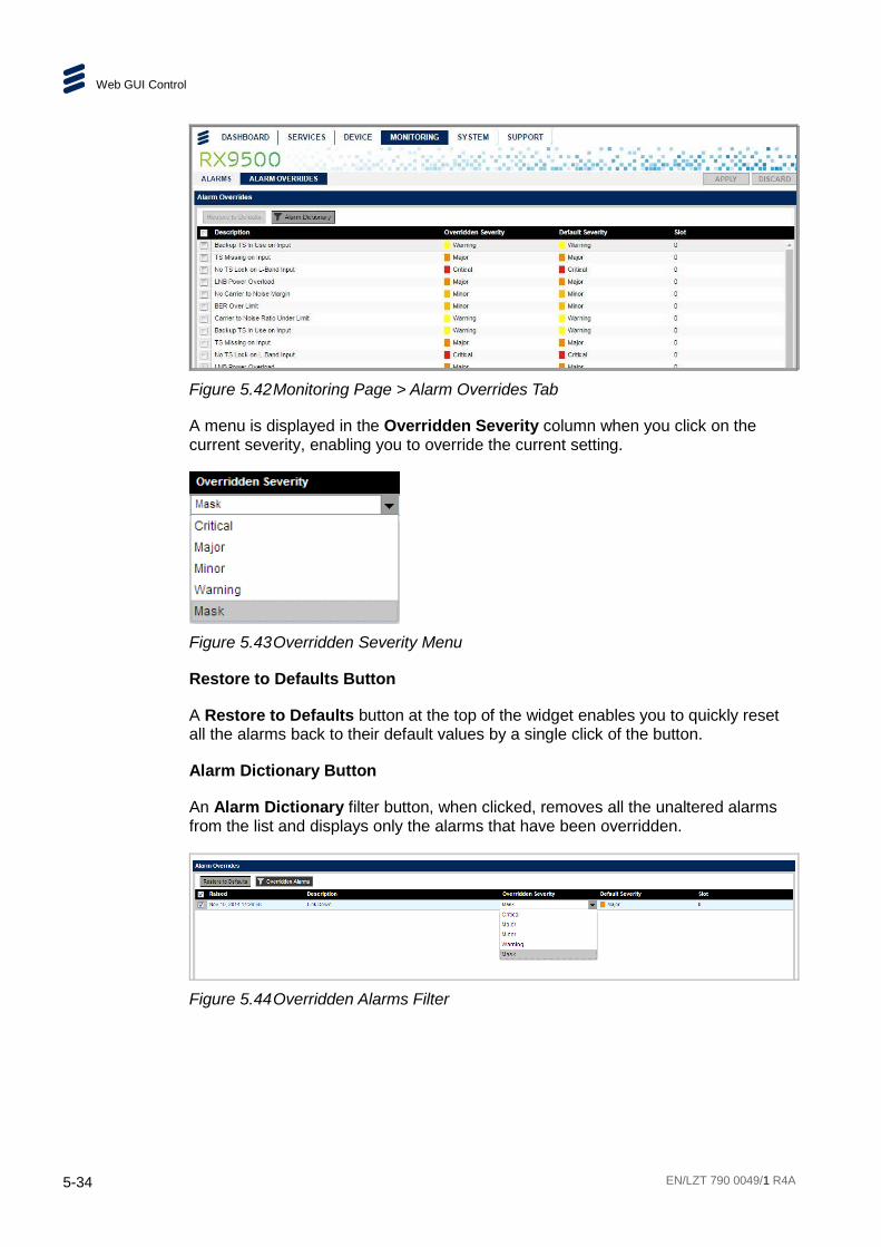
Web GUI Control
5-34 EN/LZT 790 0049/1 R4A
Figure 5.42 Monitoring Page > Alarm Overrides Tab
A menu is displayed in the Overridden Severity column when you click on the current severity, enabling you to override the current setting.
Figure 5.43 Overridden Severity Menu
Restore to Defaults Button
A Restore to Defaults button at the top of the widget enables you to quickly reset all the alarms back to their default values by a single click of the button.
Alarm Dictionary Button
An Alarm Dictionary filter button, when clicked, removes all the unaltered alarms from the list and displays only the alarms that have been overridden.
Figure 5.44 Overridden Alarms Filter

Web GUI Control
EN/LZT 790 0049/1 R4A 5-35
5.6 Support Page The Support page provides system information for the unit and provides access to the following tabs:
• Import and Export
• Log Files
5.6.1 Import and Export Tab
The Import and Export tab allows the user to import and export configurations to and from the device.
Figure 5.45 Support Page > Import and Export Tab
5.6.1.1 Import Widget
The Import widget allows the selection and import of a configuration file to the device.

Web GUI Control
5-36 EN/LZT 790 0049/1 R4A
Figure 5.46 Import Widget
The following buttons are provided:
• Browse – Clicking this button displays a dialog that enables you to navigate to the location of the configuration file to be imported.
• Import – Clicking this button imports the configuration file that has been selected using the Browse button.
5.6.1.2 Export Widget
The Export widget allows the download of a configuration file from this unit.
Figure 5.47 Export Widget
The following button is provided:
• Download – Clicking this button displays a dialog that enables you to select a location to download the unit configuration file.
5.6.2 Log Files Tab
The Log Files tab allows the user to generate log files from the unit.

Web GUI Control
EN/LZT 790 0049/1 R4A 5-37
Figure 5.48 Support Page > Log Files Tab
The widget tabulates the information as follows:
• Download log file – Clicking this button will download the log file type selected in the Log file menu. The log file will be stored, by default, on the hard disk but you may navigate to a different location, if required, in the dialog that is displayed.
• Tail log file – When this is checked, any new entry to the unit log is also updated to the remote log file.
• Log file – Selects the log file type that is to be downloaded. Clicking on the drop-down arrow displays a menu. The selected file type will be downloaded when the Download log file button is clicked.

Web GUI Control
5-38 EN/LZT 790 0049/1 R4A
BLANK
EN/LZT 790 0049/1 R4A 6-1
6 Bulk Descrambling and Networking Chapter 6
Contents 6.1 Introduction to Transport Streams ....................................................... 6-3 6.1.1 IP Encapsulation of MPEG Transport Streams .................................... 6-3 6.1.2 Mapping of MPEG-2 TS Packets ......................................................... 6-3 6.1.3 MPEG Layer ........................................................................................ 6-4 6.1.4 RTP Layer ........................................................................................... 6-4 6.1.5 UDP Layer ........................................................................................... 6-5 6.1.6 IP Layer ............................................................................................... 6-5 6.1.7 Ethernet Layer ..................................................................................... 6-5 6.1.8 IP Overhead ........................................................................................ 6-5 6.2 Transport Streams ............................................................................... 6-6 6.2.1 Overview ............................................................................................. 6-6 6.2.1.1 MPEG-2 Compliancy ........................................................................... 6-6 6.2.1.2 Transport Streams ............................................................................... 6-6 6.2.1.3 TS IP Output Parameters .................................................................... 6-6 6.2.1.4 Output Data Rate ................................................................................ 6-7 6.2.1.5 IP Port ................................................................................................. 6-7 6.2.1.6 Service Information Tables .................................................................. 6-7 6.2.1.7 Repetition Rate .................................................................................... 6-8 6.2.2 Coded Elementary Stream .................................................................. 6-8 6.2.2.1 Output Bit Rate .................................................................................... 6-8 6.3 Unit Redundancy ................................................................................. 6-8 6.3.1 Control Network Redundancy .............................................................. 6-8 6.3.1.1 Automatic Redundancy Mode .............................................................. 6-8 6.3.2 Data Network Redundancy .................................................................. 6-9 6.3.3 Same Network Mode ........................................................................... 6-9 6.3.4 Active/Active Port Mode ...................................................................... 6-9 6.4 Device Redundancy .......................................................................... 6-10 6.4.1 Standalone (No Redundancy) ........................................................... 6-10 6.5 Temperature Monitoring .................................................................... 6-10 6.5.1 Host Card Monitoring ......................................................................... 6-10 6.5.2 Option Card Monitoring ..................................................................... 6-10 6.6 Simple Network Time Protocol (SNTP) .............................................. 6-11 6.6.1 Real Time Clock ................................................................................ 6-11 6.6.1.1 SNTP Time Server ............................................................................ 6-11 6.7 Simple Network Management Protocol (SNMP) ................................ 6-12 6.7.1 Supported Protocols .......................................................................... 6-12 6.7.2 Operation .......................................................................................... 6-12

Bulk Descrambling and Networking
6-2 EN/LZT 790 0049/1 R4A
6.8 Bulk Descrambling Use-Cases .......................................................... 6-13 6.8.1 Co-located Headend and Down-link Sites ......................................... 6-13 6.8.2 Remote Located Down-link and Headend Sites ................................ 6-14 6.9 Clock and Timing .............................................................................. 6-15 6.9.1 User Configurable Parameters .......................................................... 6-15
List of Figures Figure 6.1 Mapping of MPEG-2 TS Packets ........................................................ 6-3 Figure 6.2 Mapping of MPEG-2 TS Packets ........................................................ 6-4 Figure 6.3 Mapping of MPEG-2 TS Packets ........................................................ 6-5 Figure 6.4 Interface Addressing - Same Network Mode ....................................... 6-9 Figure 6.5 Interface Addressing – Active/Active Port Mode ................................ 6-10 Figure 6.6 Bulk Descrambling and Passthrough Functions ................................ 6-13 Figure 6.7 nCompass Control ............................................................................ 6-13 Figure 6.8 Remotely Located Down-link and Headend ...................................... 6-14 Figure 6.9 IP Interfacing for Remote Down-links ................................................ 6-15
List of Tables Table 6.1 IP Overhead ........................................................................................ 6-6 Table 6.2 TS IP Output Parameters .................................................................... 6-6 Table 6.3 SNMP Interface Parameters ............................................................. 6-12 Table 6.4 Clock Configurable Parameters ........................................................ 6-15

Bulk Descrambling and Networking
EN/LZT 790 0049/1 R4A 6-3
6.1 Introduction to Transport Streams
6.1.1 IP Encapsulation of MPEG Transport Streams
An MPEG Transport Stream has the following format.
1 to 7 MPEG Transport Stream Packets
RTP Header (optional)
UDP (User Datagram Protocol)
IP (Internet Protocol)
Ethernet (IEEE 802)
Figure 6.1 Mapping of MPEG-2 TS Packets
Between one and seven MPEG transport stream packets are carried in a UDP packet.
The UDP packet may optionally also contain an Real Time Protocol (RTP) header, which adds additional information such as a sequence number and a timestamp, which can help in the detection of packet loss across a network. The RTP header is 12 bytes long.
The UDP header is 8 bytes long.
The network layer protocol is IPV4, which adds a 20 byte header to every packet.
The physical link layer is then Ethernet at either 100 Mbps or 1000 Mbps.
6.1.2 Mapping of MPEG-2 TS Packets
The mapping of MPEG-2 TS packets into IP data frames is done according to the protocol stack shown in the following illustration.

Bulk Descrambling and Networking
6-4 EN/LZT 790 0049/1 R4A
Figure 6.2 Mapping of MPEG-2 TS Packets
6.1.3 MPEG Layer
The MPEG-2/DVB layer is specified in ISO/IEC IS 13818 “Generic Coding of Moving Pictures and Associated Audio”. The main functionality of this layer is to transform MPTS (Multi-Program Transport Streams) into a number of SPTS (Single-Program Transport Streams). A Transport Stream carrying multiple programs is in this way split into a number of ‘mini’ Transport Streams, each carrying a single program. This ensures that the video can be passed through limited bandwidth links such as ADSL further down the transmission path.
6.1.4 RTP Layer
The RTP layer is optional, and will add an 8-byte RTP header to the new packet. This header contains a sequence number and a time stamp.

Bulk Descrambling and Networking
EN/LZT 790 0049/1 R4A 6-5
6.1.5 UDP Layer
The UDP layer is according to RFC768 “User Datagram Protocol”. The user can control the target UDP port number for the MPEG-2 stream. A configurable number of 188-byte long MPEG-2 TS packets are mapped straight into an UDP frame with no additional overhead. The MTU for Ethernet is usually 1500 bytes. This limits the number of MPEG-2 TS packets per UDP frame to lie within 1 to 7. The following illustration shows the mapping of MPEG-2 Transport Streams into UDP packets.
Figure 6.3 Mapping of MPEG-2 TS Packets
6.1.6 IP Layer
The IP layer is according to RFC791 “Internet Protocol Specification”. The user is allowed access to the following IP header fields: IP source address, IP destination address, Time-To-Live field, Type-Of-Service field. Performing static mapping between class-D IP addresses and the corresponding Ethernet multicast MAC addresses supports limited IP Multicasting (Type 1).
6.1.7 Ethernet Layer
The data link layer is Ethernet according to IEEE 802.3/802.3u (auto sensing 10/100 Mbps, Twisted Pair, RJ-45 connector).
6.1.8 IP Overhead
The IP overhead calculation when mapping MPEG-2 TS packets into IP frames is shown in Table 6.1.

Bulk Descrambling and Networking
6-6 EN/LZT 790 0049/1 R4A
Table 6.1 IP Overhead
Item Overhead factor Comments
MPEG-2 TS 1.0
UDP 1324/1316 = 1.006 UDP header=8 bytes
IP 1344/1324 = 1.015 IP header=20 bytes
Ethernet 1358/1344 = 1.010 Eth header=14 bytes
Total overhead factor becomes: 1.006 x 1.015 x 1.010 = 1.031 or 3.1% overhead.
Note: The number of MPEG-2 TS packets one can map down into each UDP frame is variable (between 1 and 7). Usually 7 is used for minimum overhead. This is also used in the above calculation.
6.2 Transport Streams
6.2.1 Overview
6.2.1.1 MPEG-2 Compliancy
The encapsulated Transport Stream packets (video, audio, VBI/ANC data and PCR - 188 bytes), are fully compliant MPEG-2 Transport Streams (all relevant fields completed, continuity counters, PTS/DTS, adaptation fields etc.).
6.2.1.2 Transport Streams
The system can form up to 128 output Transport Streams, with each stream mirrored on the two physical output interfaces.
Transport Streams are encapsulated in either a UDP or a UDP and RTP packet.
6.2.1.3 TS IP Output Parameters
The following parameters can be configured for a Transport Stream to be IP encapsulated and output.
Table 6.2 TS IP Output Parameters
Parameter Value Description
TS packets per UDP packet 1 to 7 [Default 7] Defines the number of Transport Stream packets encapsulated in a UDP packet
TS Mode CBR Constant bit rate output
Output Enable Off [Default] IP Output is disabled
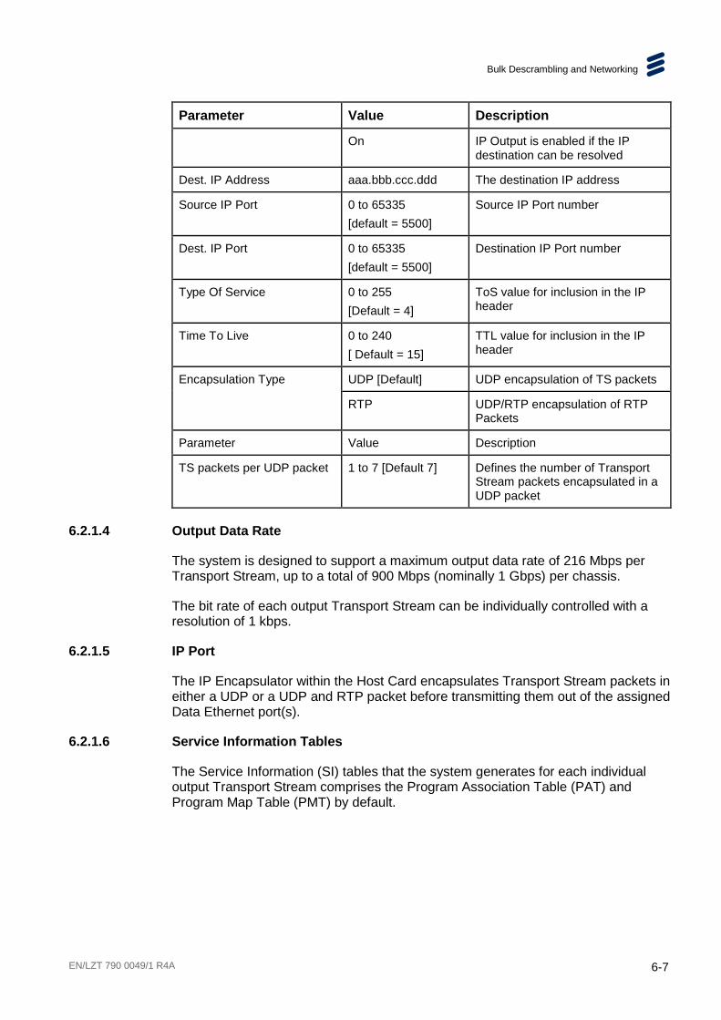
Bulk Descrambling and Networking
EN/LZT 790 0049/1 R4A 6-7
Parameter Value Description
On IP Output is enabled if the IP destination can be resolved
Dest. IP Address aaa.bbb.ccc.ddd The destination IP address
Source IP Port 0 to 65335 [default = 5500]
Source IP Port number
Dest. IP Port 0 to 65335 [default = 5500]
Destination IP Port number
Type Of Service 0 to 255 [Default = 4]
ToS value for inclusion in the IP header
Time To Live 0 to 240 [ Default = 15]
TTL value for inclusion in the IP header
Encapsulation Type UDP [Default] UDP encapsulation of TS packets
RTP UDP/RTP encapsulation of RTP Packets
Parameter Value Description
TS packets per UDP packet 1 to 7 [Default 7] Defines the number of Transport Stream packets encapsulated in a UDP packet
6.2.1.4 Output Data Rate
The system is designed to support a maximum output data rate of 216 Mbps per Transport Stream, up to a total of 900 Mbps (nominally 1 Gbps) per chassis.
The bit rate of each output Transport Stream can be individually controlled with a resolution of 1 kbps.
6.2.1.5 IP Port
The IP Encapsulator within the Host Card encapsulates Transport Stream packets in either a UDP or a UDP and RTP packet before transmitting them out of the assigned Data Ethernet port(s).
6.2.1.6 Service Information Tables
The Service Information (SI) tables that the system generates for each individual output Transport Stream comprises the Program Association Table (PAT) and Program Map Table (PMT) by default.
Bulk Descrambling and Networking
6-8 EN/LZT 790 0049/1 R4A
6.2.1.7 Repetition Rate
The repetition rate of Service Information (SI) packets must take into account the output Transport Stream rate, otherwise the jitter introduced by the multiplexing of packets to form the Transport Stream can lead to the SI repetition rate being too long.
6.2.2 Coded Elementary Stream
The compressed output streams from the module are in the form of MPEG-2 transport packets that have been encapsulated into a Transport Stream packet.
6.2.2.1 Output Bit Rate
The output rate of the transport packets is derived from the 27 MHz reference clock and is accurate to within 1 kbps of the configured transport bit rate.
The host supports bit-stuffing to maintain configured bit rate if the operating mode requires it.
6.3 Unit Redundancy
6.3.1 Control Network Redundancy
The control network is assigned to the physical Ethernet ports CTL1 and CTL2. CTL1 is considered to be the primary port and CTL2 the spare.
If both control ports have a link up, the primary port will respond to network traffic but the spare port will not. However, if the link goes down on the primary port, then the spare port will start to respond to network traffic.
6.3.1.1 Automatic Redundancy Mode
In Automatic Redundancy Mode the primary port is used as default. If the primary port link fails, control passes to the secondary port. However, if the primary port link is restored then control passes back to the primary after the Auto-Revert delay period.
The behavior of the system when the primary link is re-established depends on the Control Port Auto-Revert Time setting.
If the Control Port Auto-Revert Time is set to 0, then the spare port remains the active control port until its link goes down.
Otherwise, after the primary port has had a link present for the defined period of time, it will resume being the active control port, and the spare port will cease outputting to network traffic.

Bulk Descrambling and Networking
EN/LZT 790 0049/1 R4A 6-9
6.3.2 Data Network Redundancy
The unit has two Ethernet data ports operating as paired outputs. These are designated Ge3 and Ge4.
Each port may have a different IP address, MAC address, subnet mask and default gateway, providing output network redundancy. Both ports are Active
If both ports are configured to be on the same subnet, only one port will respond to ICMP messages.
The data ports can raise an alarm during abnormal operational conditions, see Chapter 8, Preventive Maintenance and Fault-finding.
6.3.3 Same Network Mode
In a Same Network Mode (also known as a Same Subnet Mode), both interfaces are connected into the same network segments and must be isolated at the L2 level. In this mode, every multicast uses a common virtual IP address for both interfaces. Both interfaces use the same subnet mask and gateway IP address.
(S1,G1)IP address 192.168.1.2Subnet Mask 255.255.255.0Gateway 192.168.1.254
(S1,G1)
Main DeviceIP address 192.168.1.3Subnet Mask 255.255.255.0Gateway 192.168.1.254
Virtual IP address 192.168.1.1
Figure 6.4 Interface Addressing - Same Network Mode
The Internet Group Management Protocol (IGMP) join is made using the physical interface.
Note: Redundant pairs of control interfaces only support same network mode and active/standby mode.
6.3.4 Active/Active Port Mode
An Active/Active Port Mode can be applied to output data interfaces only. In this mode, interfaces are either transmitting or receiving simultaneously.
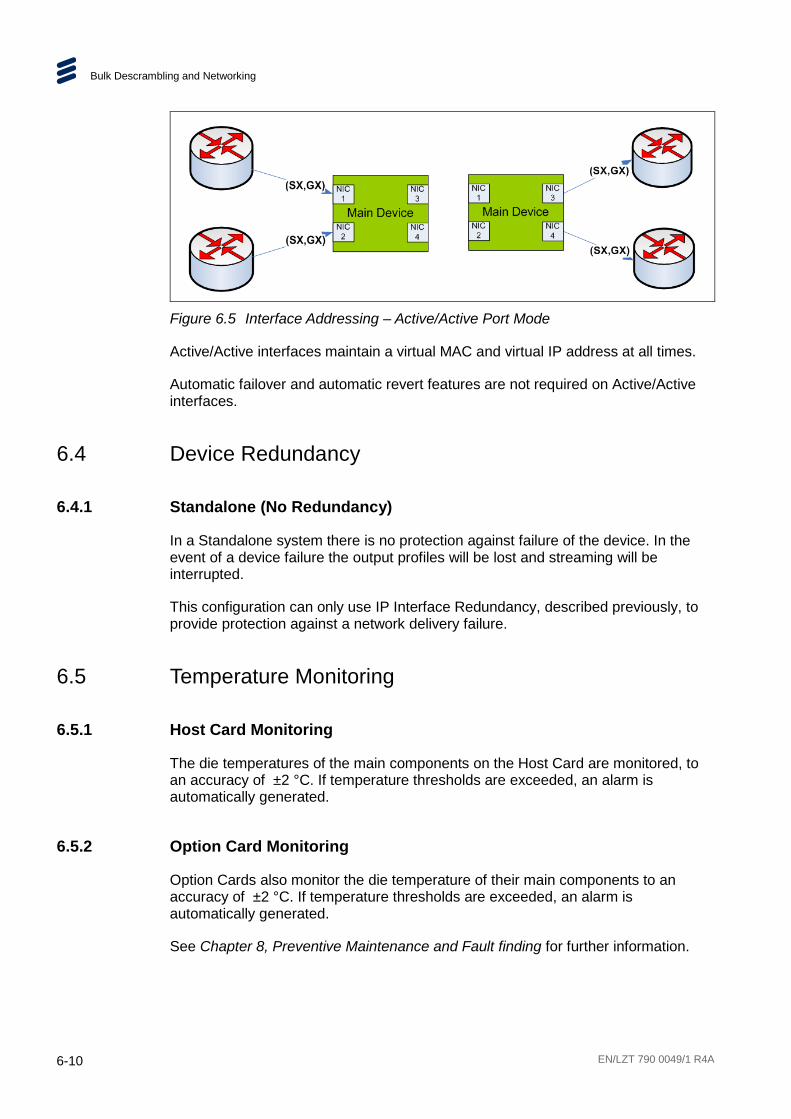
Bulk Descrambling and Networking
6-10 EN/LZT 790 0049/1 R4A
Figure 6.5 Interface Addressing – Active/Active Port Mode
Active/Active interfaces maintain a virtual MAC and virtual IP address at all times.
Automatic failover and automatic revert features are not required on Active/Active interfaces.
6.4 Device Redundancy
6.4.1 Standalone (No Redundancy)
In a Standalone system there is no protection against failure of the device. In the event of a device failure the output profiles will be lost and streaming will be interrupted.
This configuration can only use IP Interface Redundancy, described previously, to provide protection against a network delivery failure.
6.5 Temperature Monitoring
6.5.1 Host Card Monitoring
The die temperatures of the main components on the Host Card are monitored, to an accuracy of ±2 °C. If temperature thresholds are exceeded, an alarm is automatically generated.
6.5.2 Option Card Monitoring
Option Cards also monitor the die temperature of their main components to an accuracy of ±2 °C. If temperature thresholds are exceeded, an alarm is automatically generated.
See Chapter 8, Preventive Maintenance and Fault finding for further information.
Bulk Descrambling and Networking
EN/LZT 790 0049/1 R4A 6-11
6.6 Simple Network Time Protocol (SNTP) The unit can obtain the current time from a network time server using SNTPv4 (RFC 4330) and is capable of working with Microsoft Windows Time, (SNTP as defined in RFC 1767).
6.6.1 Real Time Clock
The Host Controller card has a real time clock, which is battery powered when the chassis is unpowered, so that the time and date is maintained. This clock is designed to be accurate to ±1 minute per month. The battery is capable of powering the clock for over two years. See Clock and Timing on page 6-15.
6.6.1.1 SNTP Time Server
If an SNTP Time Server is selected, and communications are established with it, then the unit uses the time obtained to correct the system’s real time clock, and the user cannot set the clock.
If a time server has been configured, but it fails to respond, then an ‘SNTP Server Failed To Respond’ alarm is generated.
An SNTP server can be configured to update the clock and calendar or else the user can update the time and date. Any changes to the time and date are recorded in the system log.
The real time clock is used to set the time and date when the unit is started, but then its own time and date is maintained, unless a change to the time and date parameters occur, when it will be updated to the new settings.
The system can set or correct its system clock from information received from an SNTP Time Server. More specifically it supports SNTP V4 and also Microsoft Windows Time (W32Time), which means that it supports NTP V3.
The user can enter the IP address of the SNTP server to be used, the default address is 000.000.000.000, which indicates to the system that no SNTP server has been defined, and therefore SNTP is disabled.
If an SNTP server is defined, and it fails to respond, then an SNTP Server Timeout alarm will be raised. This alarm will be de-asserted either when an SNTP response is received, or the SNTP functionality is disabled.
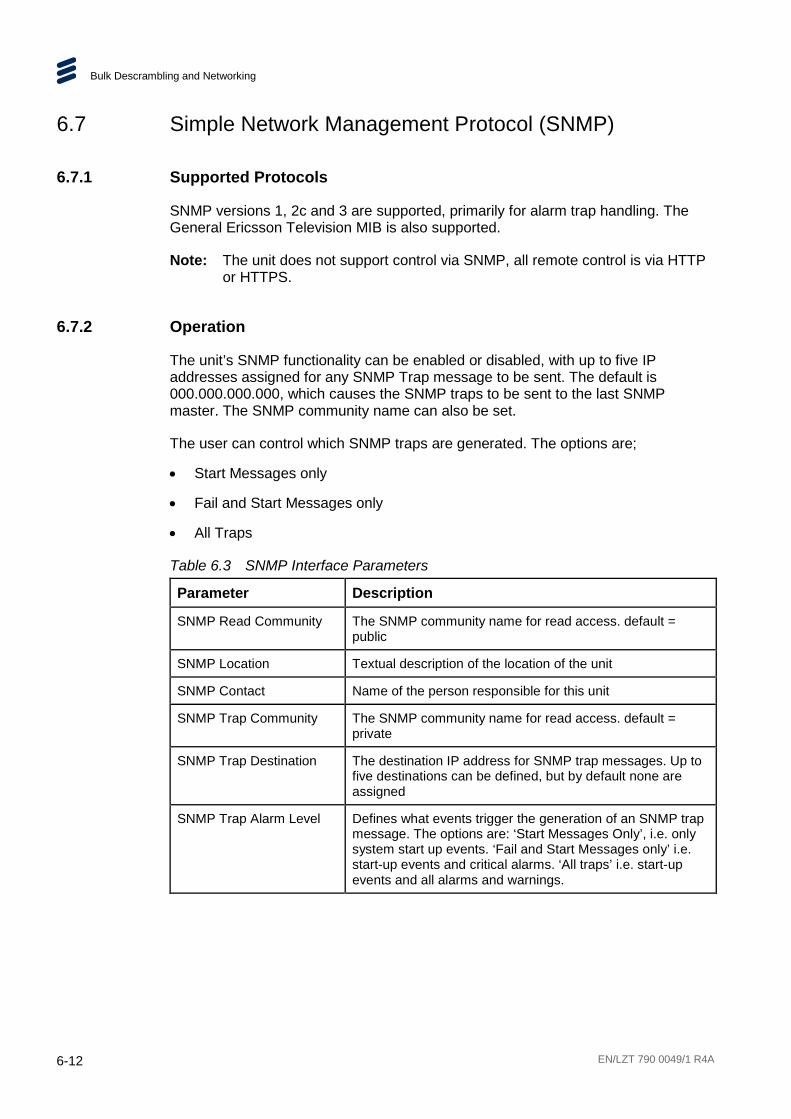
Bulk Descrambling and Networking
6-12 EN/LZT 790 0049/1 R4A
6.7 Simple Network Management Protocol (SNMP)
6.7.1 Supported Protocols
SNMP versions 1, 2c and 3 are supported, primarily for alarm trap handling. The General Ericsson Television MIB is also supported.
Note: The unit does not support control via SNMP, all remote control is via HTTP or HTTPS.
6.7.2 Operation
The unit’s SNMP functionality can be enabled or disabled, with up to five IP addresses assigned for any SNMP Trap message to be sent. The default is 000.000.000.000, which causes the SNMP traps to be sent to the last SNMP master. The SNMP community name can also be set.
The user can control which SNMP traps are generated. The options are;
• Start Messages only
• Fail and Start Messages only
• All Traps
Table 6.3 SNMP Interface Parameters
Parameter Description
SNMP Read Community The SNMP community name for read access. default = public
SNMP Location Textual description of the location of the unit
SNMP Contact Name of the person responsible for this unit
SNMP Trap Community The SNMP community name for read access. default = private
SNMP Trap Destination The destination IP address for SNMP trap messages. Up to five destinations can be defined, but by default none are assigned
SNMP Trap Alarm Level Defines what events trigger the generation of an SNMP trap message. The options are: ‘Start Messages Only’, i.e. only system start up events. ‘Fail and Start Messages only’ i.e. start-up events and critical alarms. ‘All traps’ i.e. start-up events and all alarms and warnings.
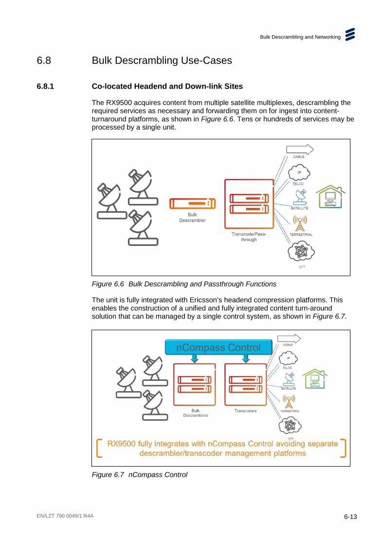
Bulk Descrambling and Networking
EN/LZT 790 0049/1 R4A 6-13
6.8 Bulk Descrambling Use-Cases
6.8.1 Co-located Headend and Down-link Sites
The RX9500 acquires content from multiple satellite multiplexes, descrambling the required services as necessary and forwarding them on for ingest into content-turnaround platforms, as shown in Figure 6.6. Tens or hundreds of services may be processed by a single unit.
Figure 6.6 Bulk Descrambling and Passthrough Functions
The unit is fully integrated with Ericsson’s headend compression platforms. This enables the construction of a unified and fully integrated content turn-around solution that can be managed by a single control system, as shown in Figure 6.7.
Figure 6.7 nCompass Control

Bulk Descrambling and Networking
6-14 EN/LZT 790 0049/1 R4A
6.8.2 Remote Located Down-link and Headend Sites
In order to permit downlink sites to be geographically located remotely from the headend, the RX9500 now accepts IP inputs. This allows bulk demodulation of L-band satellite inputs at the downlink site with an IP Transport Stream output. Bulk descramble can then take place at the headend using IP Transport Stream input, as shown in Figure 6.8.
Figure 6.8 Remotely Located Down-link and Headend
IP connectivity between the two sites provides practical benefits for the user and flexibility for designing content-turnaround solutions. This may be of use when:
• the headend site does not have enough space for satellite dishes.
• the headend does not have line-of-site to the satellite.
• encrypted sources outside the Ericsson system are required to be ingested as IP feeds.
In applications where a separate down-link site is employed, an RX9500 is installed at the down-link location to provide a bulk demodulation function. A second RX9500 is installed at the headend site to provide a bulk descrambling function. Descrambled services can then be passed from the 2nd RX9500 unit to a subsequent transcode or video monitoring process.
The RX9500 at the down-link site can be configured to demodulate the satellite services of interest. This “demodulation” RX9500 unit can be set to pass only the services that are required for subsequent descrambling over the IP network. Each service filtered satellite multiplex is sent as an MPTS stream over the IP network. The 2nd “descrambling” RX9500 then performs Common Interface descrambling on the received services outputting each descrambled service as individual SPTSs.
If, as part of the required new service line-up some satellite services exist as Free-to-Air (FTA) on the satellite transponder, these FTA services can simply be routed directly from the “demodulation” RX9500 to the transcode head-end (bypassing the second “descrambling” RX9500).

Bulk Descrambling and Networking
EN/LZT 790 0049/1 R4A 6-15
Figure 6.9 IP Interfacing for Remote Down-links
6.9 Clock and Timing The Host Controller card has a real time clock, which is battery powered when the chassis is unpowered, so that the time and date is maintained. This clock is designed to be accurate to ±1 minute per month. The battery is capable of powering the clock for over two years.
6.9.1 User Configurable Parameters
The user configurable parameters associated with the clock are defined below
Table 6.4 Clock Configurable Parameters
Parameter Values Description
Local Time hh:mm:ss Current local time in hours minutes and seconds
Local Date dd:mm:yyyy Current date in day month and year

Bulk Descrambling and Networking
6-16 EN/LZT 790 0049/1 R4A
BLANK
EN/LZT 790 0049/1 R4A 7-1
Options, Licensing and Upgrades Chapter 7
Contents 7.1 Introduction ......................................................................................... 7-3 7.1.1 Option Cards Available at this Release ................................................ 7-3 7.1.2 Option Card Combinations .................................................................. 7-3 7.2 Satellite Input Common Interface Descrambling Card ......................... 7-4 7.2.1 RF Input Connector ............................................................................. 7-4 7.2.2 Conditional Access Modules ................................................................ 7-4 7.2.3 Satellite Input Specification .................................................................. 7-4 7.3 Removal and Replacement of Modules ............................................... 7-5 7.3.1 Handling Modules ................................................................................ 7-5 7.3.2 Electrostatic Discharge ........................................................................ 7-5 7.3.3 Installing a New Module ...................................................................... 7-6 7.3.4 Removing a Module ............................................................................. 7-7 7.3.5 Replacing (Hot-Swapping) a Module ................................................... 7-7 7.4 Obtaining New Licenses ...................................................................... 7-8 7.4.1 Time Limited Licenses ......................................................................... 7-8 7.4.2 Dual Counter Licenses ........................................................................ 7-9 7.5 Installing Software and Firmware Upgrades ........................................ 7-9 7.5.1 Upgrading Using the Supplied Files ..................................................... 7-9 7.5.2 Upgrading Using the Mini-USB ............................................................ 7-9
List of Figures Figure 7.1 Option Card Slot Numbering ................................................................ 7-3 Figure 7.2 Satellite Input Common Interface Descrambling Card ......................... 7-4 Figure 7.3 Inserting and Withdrawing Modules ..................................................... 7-5
List of Tables Table 7.1 Option Cards Available at this Release ................................................ 7-3 Table 7.2 Option Card Combinations .................................................................. 7-3

Options, Licensing and Upgrades
7-2 EN/LZT 790 0049/1 R4A
BLANK
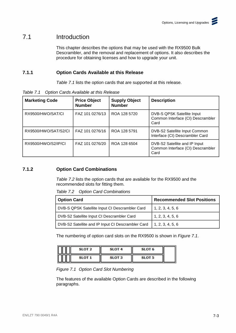
Options, Licensing and Upgrades
EN/LZT 790 0049/1 R4A 7-3
7.1 Introduction This chapter describes the options that may be used with the RX9500 Bulk Descrambler, and the removal and replacement of options. It also describes the procedure for obtaining licenses and how to upgrade your unit.
7.1.1 Option Cards Available at this Release
Table 7.1 lists the option cards that are supported at this release.
Table 7.1 Option Cards Available at this Release
Marketing Code Price Object Number
Supply Object Number
Description
RX9500/HWO/SAT/CI FAZ 101 0276/13 ROA 128 5720 DVB-S QPSK Satellite Input Common Interface (CI) Descrambler Card
RX9500/HWO/SAT/S2/CI FAZ 101 0276/16 ROA 128 5791 DVB-S2 Satellite Input Common Interface (CI) Descrambler Card
RX9500/HWO/S2/IP/CI FAZ 101 0276/20 ROA 128 6504 DVB-S2 Satellite and IP Input Common Interface (CI) Descrambler Card
7.1.2 Option Card Combinations
Table 7.2 lists the option cards that are available for the RX9500 and the recommended slots for fitting them.
Table 7.2 Option Card Combinations
Option Card Recommended Slot Positions
DVB-S QPSK Satellite Input CI Descrambler Card 1, 2, 3, 4, 5, 6
DVB-S2 Satellite Input CI Descrambler Card 1, 2, 3, 4, 5, 6
DVB-S2 Satellite and IP Input CI Descrambler Card 1, 2, 3, 4, 5, 6
The numbering of option card slots on the RX9500 is shown in Figure 7.1.
Figure 7.1 Option Card Slot Numbering
The features of the available Option Cards are described in the following paragraphs.

Options, Licensing and Upgrades
7-4 EN/LZT 790 0049/1 R4A
7.2 Satellite Input Common Interface Descrambling Card The Satellite Input Common Interface (CI) Descrambling Card is enabled for DVB-S reception but can also be licensed to support the DVB-S2 Satellite Transmission Standard.
Up to 6 cards can be fitted in the RX9500, depending on the base chassis. Further functionality is provided by the purchase of feature licenses.
Figure 7.2 Satellite Input Common Interface Descrambling Card
7.2.1 RF Input Connector
An L-Band Input (F-type) connector is provided for the reception of the RF Input. See Chapter 2, Installing the Equipment for further details of this connector.
7.2.2 Conditional Access Modules
Each card can host up to two Common Interface (CI) Conditional Access Modules (CAMs).
The following CAMs are supported:
• Conax Neotion CAM (DVB-CI)
• Conax SMiT 1 channel
• Conax SMiT 8 channel
• Conax SMiT ICECRYPT
• Irdeto SMiT 1 channel
• Irdeto SMiT 8 channel
• Irdeto SMiT ICECRYPT
7.2.3 Satellite Input Specification
See Annex B, Technical Specification for details of this input specification and supported licensed modes.

Options, Licensing and Upgrades
EN/LZT 790 0049/1 R4A 7-5
7.3 Removal and Replacement of Modules This section gives information relating to the handling of option modules as they are inserted or removed from the unit.
7.3.1 Handling Modules
Caution!
Care must be taken to when inserting or withdrawing modules to avoid damage to underside components.
Modules must be kept orthogonal, i.e. at 90 degrees to the unit, to avoid catching underside components on the chassis.
Figure 7.3 Inserting and Withdrawing Modules
Caution!
Do not plug in modules with excessive force as this may result in damage to the module connector or other components. If any significant resistance to inserting a module is felt, withdraw the module slightly and check for obstructions.
7.3.2 Electrostatic Discharge
Warning!
Static electricity can damage electronic components. To avoid damage, keep modules in their static-protective package until you are ready to install them.
Options, Licensing and Upgrades
7-6 EN/LZT 790 0049/1 R4A
To reduce the possibility of electrostatic discharge, observe the following precautions:
• Where possible ensure that antistatic protection is worn (for example an earthed antistatic wrist strap, an ankle or heel strap).
• Handle modules carefully, holding them by edges or rear panels.
• Do not touch solder joints, pins, or exposed printed circuitry.
• Do not leave the modules where others can handle and possibly damage them.
• While the module is still in its anti-static package, touch it to an unpainted metal part of the system unit for at least two seconds. (This drains static electricity from the package and from your body).
• Remove the module from its package and install it directly into your base chassis without setting it down. If it is necessary to set the module down, place it in its static-protective package.
• Take additional care when handling modules during cold weather, because heating reduces indoor humidity and increases static electricity.
7.3.3 Installing a New Module
A new module can be inserted when the unit is powered off or on. When inserted and powered, the unit will determine the module capabilities and make it available for configuration. Initially a default set of parameters will be in place. As long as there are licenses available for the features required, the module can then be configured and used immediately.
Caution!
To avoid damaging the module, always handle carefully (see section 7.3.1) and avoid electrostatic discharge (see section 7.3.2).
To install a new module:
1. Remove the blanking plate from the module slot in which the new module is to be fitted.
2. Carefully remove the new module from its anti-static package, and insert it in to the base unit, slotting the module edges in to the module guides.
3. Push the module home, so that the rear panel is flush with the rear of the base unit.
4. Tighten the two captive retaining screws.
5. When the chassis detects a new card fitted, it will be displayed on the Dashboard, and an alarm will be raised. If all options are reported correctly, the
Options, Licensing and Upgrades
EN/LZT 790 0049/1 R4A 7-7
Accept Hardware Configuration needs to be applied. This will accept the new hardware configuration and clear the alarm.
7.3.4 Removing a Module
Caution!
To avoid damaging the module, always handle carefully (see Section 7.3.1) and avoid electrostatic discharge (see Section 7.3.2).
To remove a module:
1. Loosen the two captive screws that retain the module in the base unit.
2. Holding the captive screws, pull the module from the unit and place it in suitable anti-static packaging.
3. Fit a blanking panel in place of the removed module.
4. When the unit detects a card is no longer present, it will be displayed on the Option Slots web page, and an alarm will be raised. If all options are reported correctly, the Accept Option Slot Configuration needs to be applied. This will accept the new hardware configuration and clear the alarm.
7.3.5 Replacing (Hot-Swapping) a Module
A module can be replaced without powering down the base unit, i.e. can be ‘hot-swapped’. This will cause services to be allocated to other modules, enabling the removal of the module in question. In this way, essential maintenance can be carried out with minimum disruption. To perform a hot-swap, the modules should only be unplugged or inserted when the unit is fully booted and configured.
Only ONE module should be ‘hot-swapped’ at a time, to prevent problems due to inrush current, and to ensure that the host recognizes and configures the new module. If more than one module is being fitted, a wait time of approximately 10 s is recommended between inserting each module.
Caution!
To avoid damaging the module, always handle carefully (see section 7.3.1) and avoid electrostatic discharge (see section 7.3.2).
The process to replace (hot-swap) an option card:
1. Disconnect any cables from the option card to be replaced.
2. Loosen the two captive screws that retain the option card in the base chassis.
Options, Licensing and Upgrades
7-8 EN/LZT 790 0049/1 R4A
3. Holding the captive screws, pull the option card from the unit, (observe the handling precautions).
4. Carefully remove the replacement option card from its anti-static package, and insert it in to the base chassis, slotting the card edges in to the card guides.
5. Push the card home, so that the rear panel is flush with the rear of the base chassis.
6. Tighten the two captive retaining screws.
7. Connect any external cables to the replacement option card.
Note: If the replacement card is of the same type as the failed card, then it will be automatically configured to the same settings as the failed card. If the replacement card is of a different type then an alarm will be generated.
The unit regularly monitors to verify module presence and to detect if a module has been removed or added.
When a new module is inserted it will start-up and attempt to link to the host controller. When this link has been established the process of identifying the module and its capabilities begins. Once this is established, the module will be configured with the same configuration as the module that has been replaced (assuming that the replacement module has the same capabilities).
7.4 Obtaining New Licenses The functionality of the RX9500 depends on the hardware options fitted and the software options installed. Software options are enabled or disabled by means of ‘license keys’. A license key is a string of numbers which, when downloaded to a unit, will enable a specific feature or feature set.
License keys can be purchased from your local Ericsson sales representative. License keys may be installed by the user, allowing field upgrading of units to be performed simply.
The unit comes with the option cards and licenses, which were ordered, already installed. All licenses are stored on the host card (Slot 0).
To verify which licenses are installed and enabled or to order new licenses, see Chapter 3, Getting Started.
7.4.1 Time Limited Licenses
Time limited licenses provide access to certain defined features for a set number of days (i.e. Duration). When the feature is in use the remaining time will be decremented every minute (i.e. Remaining)
When the feature is not in use the Remaining time stops decrementing. When the Remaining time runs out the feature is disabled / not accessible.

Options, Licensing and Upgrades
EN/LZT 790 0049/1 R4A 7-9
7.4.2 Dual Counter Licenses
Dual counter licenses are supplied in situation where a unit may be used as an occasional backup for the main unit. The purpose of this license is that the unit can be used as a stand-in for a short period of time, for instance while maintenance is performed on the main unit, but it prevents the unit from being uses as a long-term replacement or as an additional unit.
As the name suggests there are two timers in use. When the licensed feature is initially enabled, the Grace period timer is decremented. If the Grace period timer expires then the Remaining timer is decremented. If the license is released (i.e. the feature is not in use) then the Grace counter is reset to its initial value, allowing the re-use of the Grace period. However, if the feature continues to be used and the Remaining timer runs out, the feature is disabled / not accessible.
7.5 Installing Software and Firmware Upgrades In the event of a failed upgrade, please contact Customer Support for assistance.
7.5.1 Upgrading Using the Supplied Files
New software and firmware versions for your RX9500 unit may be supplied, enabling you to upgrade your unit(s) to install bug fixes or add new functionality.
To install a firmware upgrade:
1. Contact your Ericsson representative and specify the upgrade required plus the serial numbers of your unit(s).
2. Your upgrade will be supplied as a set of files. This is a wizard that will guide you through the installation procedure.
3. Save the file to your computer.
4. Run the .jar file (by double-clicking on it) which will launch the upgrade wizard.
7.5.2 Upgrading Using the Mini-USB
Upgrading is also possible using front panel USB port (using a mini-USB adaptor).
To install an upgrade:
1. Contact your Ericsson representative and specify the upgrade required plus the serial numbers of your unit(s).
2. Plug the USB device in with the upgrade files located at the root. The upgrade files will be automatically detected.
3. Follow the on-screen instructions at the front panel display to install the upgrade.

Options, Licensing and Upgrades
7-10 EN/LZT 790 0049/1 R4A
BLANK
EN/LZT 790 0049/1 R4A 8-1
Preventive Maintenance and Fault-finding Chapter 8
Contents 8.1 Introduction ......................................................................................... 8-3 8.2 Preventive Maintenance ...................................................................... 8-3 8.2.1 Routine Inspection ............................................................................... 8-3 8.2.2 Cleaning .............................................................................................. 8-3 8.2.3 Servicing ............................................................................................. 8-3 8.2.3.1 Damage Requiring Service .................................................................. 8-3 8.2.3.2 Replacement Parts .............................................................................. 8-4 8.2.3.3 Checks on Completion of Servicing ..................................................... 8-4 8.3 Maintenance and Support.................................................................... 8-4 8.3.1 Introduction ......................................................................................... 8-4 8.3.2 Warranty .............................................................................................. 8-4 8.3.3 Levels of Continuing Ericsson Service Support ................................... 8-4 8.4 Alarms ................................................................................................. 8-5 8.4.1 Alarm Monitoring ................................................................................. 8-5 8.4.2 Alarms - Control Port ......................................................................... 8-10 8.4.3 Alarms - Data Port ............................................................................. 8-11 8.4.4 Alarms - Option Cards ....................................................................... 8-11 8.5 Fault-finding....................................................................................... 8-12 8.5.1 Fault-finding Philosophy .................................................................... 8-12 8.5.2 Preliminary Checks............................................................................ 8-12 8.5.3 Power Supply Problems/Unit Not Working ......................................... 8-13 8.5.3.1 Fuse Replacement ............................................................................ 8-13 8.5.3.2 Lithium Battery .................................................................................. 8-14 8.5.4 Fan(s) Not Working/Overheating ....................................................... 8-14 8.5.5 Cannot Access Web GUI ................................................................... 8-15 8.5.6 Communications (Control Port/Data Port) Alarms .............................. 8-15 8.5.7 Cannot Ping the Unit ......................................................................... 8-16 8.5.8 Configuration Problems ..................................................................... 8-16 8.6 SNMP Traps ...................................................................................... 8-17 8.6.1 What Is An SNMP Trap? ................................................................... 8-17 8.6.2 Supported Protocols .......................................................................... 8-18 8.6.3 Operation .......................................................................................... 8-18 8.6.4 SNMP Interface Parameters .............................................................. 8-18 8.7 Viewing Log Files .............................................................................. 8-19 8.8 Importing and Exporting Configurations ............................................. 8-19 8.9 Calling a Service Engineer ................................................................ 8-19

Preventive Maintenance and Fault-finding
8-2 EN/LZT 790 0049/1 R4A
List of Tables Table 8.1 Alarms List .......................................................................................... 8-6 Table 8.2 Alarms - Control Port......................................................................... 8-10 Table 8.3 Alarms - Data Port ............................................................................ 8-11 Table 8.4 Power Supply Problems/Unit Not Working ........................................ 8-13 Table 8.5 Fans Not Working/Overheating ......................................................... 8-14 Table 8.6 Cannot Access Web GUI .................................................................. 8-15 Table 8.7 Control Ports Alarms ......................................................................... 8-15 Table 8.8 Data Ports Alarms ............................................................................. 8-15 Table 8.9 Cannot Ping the Unit ......................................................................... 8-16 Table 8.10 Configuration Problems ..................................................................... 8-17 Table 8.11 SNMP Interface Parameters ............................................................. 8-18

Preventive Maintenance and Fault-finding
EN/LZT 790 0049/1 R4A 8-3
8.1 Introduction This chapter details the schedules and instructions, where applicable, for routine inspection, cleaning and maintenance of the equipment which should be performed by an operator. It also details basic fault-finding procedures.
8.2 Preventive Maintenance
8.2.1 Routine Inspection
Check cooling fan operation regularly. The fans are temperature controlled so may not be on if the ambient temperature is low. Refer to Annex B, Technical Specification for more information.
Note: Failure to ensure a free flow of air around the unit may cause overheating. This condition is detected by a temperature sensor on the Host Card or an Option Card and causes the alarm to be raised.
8.2.2 Cleaning
Caution!
Do not use liquid cleaners or aerosol cleaners.
Unplug the unit from the wall outlet before cleaning the exterior with a damp cloth. Do not use liquid cleaners or aerosol cleaners.
Note: Only the exterior of the case should be cleaned.
8.2.3 Servicing
8.2.3.1 Damage Requiring Service
Warning!
Do not remove the top cover of this equipment. Hazardous voltages are present within this equipment and may be exposed if the top cover is removed. Only Ericsson trained and approved service engineers are permitted to service this equipment.
Unplug the equipment from the wall outlet and refer servicing to qualified service personnel under the following conditions:

Preventive Maintenance and Fault-finding
8-4 EN/LZT 790 0049/1 R4A
• When the power supply cord or plug is damaged.
• If liquid has been spilled, or objects have fallen into the product.
• If the product has been exposed to rain or water.
• If the product does not operate normally by following the operating instructions.
• If the product has been dropped or the case has been damaged.
• When the product exhibits a distinct change in performance.
8.2.3.2 Replacement Parts
When replacement parts are required, be sure the service technician has used parts specified by the manufacturer or which have the same characteristics as the original part. Unauthorized substitutions may result in fire, electric shock or other hazards.
8.2.3.3 Checks on Completion of Servicing
Upon completion of any service or repairs to this product, ask the service technician to perform electrical safety checks to determine that the product is in a safe operating condition. Also, performance and EMC checks may be required.
8.3 Maintenance and Support
8.3.1 Introduction
Ericsson is a leader in the design, integration and implementation of digital broadcasting products and systems. It has a large team dedicated to keeping our customers on-air 24 hours a day, 365 days a year.
With regional offices worldwide, and ultra-modern specialist service facilities in the US, UK, and Asia, Ericsson covers the world. There is a customer service centre open round the clock, every day of the year.
Years of design and support experience enable it to offer a range of service options that will meet your needs at a price that makes sense.
8.3.2 Warranty
All Ericsson products and systems are designed and built to the highest standards and are covered under a comprehensive 12 month warranty.
8.3.3 Levels of Continuing Ericsson Service Support
For standalone equipment, then Ericsson BASIC Essential support is the value for money choice for you. BASIC provides you with year-by-year Service long after the warranty has expired.

Preventive Maintenance and Fault-finding
EN/LZT 790 0049/1 R4A 8-5
For systems support you can choose either Gold Business Critical support or Silver Business Advantage. These packages are designed to save you costs and protect your income through enlisting the help of Ericsson support specialists.
Call Ericsson Sales for more details.
8.4 Alarms
8.4.1 Alarm Monitoring
Active Alarms
The alarm status of the unit is available on the Active Alarms tab of the Alarms widget on the Dashboard. All currently active alarms are displayed, along with details of the time and date that the alarm was raised, the severity and description of the alarm and which module the alarm is associated with.
Alarm History
A complete history of all alarms raised and cleared since the last power cycle is displayed on the Alarm History tab of the Alarms widget on the Dashboard.
Alarm Masking
The severity of the currently active alarms and those displayed on the History tab can be edited if required. For this, open the required alarm, and change the severity to be a warning, minor, major, critical or masked.
Note: If the alarm is masked it will not be displayed on any of the reporting interfaces, and will not produce an SNMP trap message.
Alerts are GUI based only (indicate a field has been entered incorrectly for example). Alerts don't generate SNMP traps or get used as a basis for a redundancy switch.
See Chapter 3, Getting Started for details of how to monitor alarms on the Front Panel and web GUI pages.

Preventive Maintenance and Fault-finding
8-6 EN/LZT 790 0049/1 R4A
Table 8.1 Alarms List
Alarm Description Remedial action Severity (Default)
AVP General Alarms
Alarm : Fans failure A chassis fan has stopped or failed to respond.
Call Support. Major
Alarm : Temperature over critical
Chassis internal temperature has exceeded max rating.
Check environment temperature, inlet and outlet vents and fan operation. Recommend power down equipment.
Critical
Alarm : Temperature under critical
Chassis internal temperature has exceeded min rating.
Check environment temperature.
Information
Alarm : PSU 1 failure
PSU 1 output has failed or has reported an internal failure.
Call Support. Major
Alarm : PSU 2 failure
PSU 2 output has failed or has reported an internal failure.
Call Support. Major
Alarm : Primary IP address conflict failure
Output stream is configured to use a specific source IP address on the primary output; however, this can't be used due to a conflict with another device on the network. Transport Stream is not playing out.
Resolve the IP address conflict by changing the specific source address or the conflicting address of the other device.
Major
Alarm : Primary IP address conflict defending
Output Transport Stream is using a specific source IP address on the primary output, but a conflict has been detected with this address from another device on the network. Transport Stream is playing out.
Resolve the IP address conflict by changing the specific source address or the conflicting address of the other device.
Major

Preventive Maintenance and Fault-finding
EN/LZT 790 0049/1 R4A 8-7
Alarm Description Remedial action Severity (Default)
Alarm : Secondary IP address conflict failure
Output stream is configured to use a specific source IP address on the secondary output; however, this can't be used due to a conflict with another device on the network. Transport Stream is not playing out.
Resolve the IP address conflict by changing the specific source address or the conflicting address of the other device.
Major
Alarm : Secondary IP address conflict defending
Output Transport Stream is using a specific source IP address on the secondary output, but a conflict has been detected with this address from another device on the network. Transport Stream is playing out.
Resolve the IP address conflict by changing the specific source address or the conflicting address of the other device.
Major
Alarm : Primary unicast address lost
Output Transport Stream is being delivered by unicast on the primary output, but the destination IP address can't be contacted.
Check connectivity between the primary output network and the destination device.
Warning
Alarm : Secondary unicast address lost
Output Transport Stream is being delivered by unicast on the secondary output, but the destination IP address can't be contacted.
Check connectivity between the primary output network and the destination device.
Warning
Alarm : Link down Physical interface link status is DOWN.
Check physical connection and status of link partner.
Major
Alarm : Physical IP address conflict failure
Same as Primary IP address conflict failure, but applies to the IP address of the data network interface.
Resolve the IP address conflict by changing the data network IP address or the conflicting address of the other device.
Major
Alarm : Physical IP address conflict defending
Same as Primary IP address conflict defending, but applies to the IP address of the data network interface.
Resolve the IP address conflict by changing the data network IP address or the conflicting address of the other device.
Major

Preventive Maintenance and Fault-finding
8-8 EN/LZT 790 0049/1 R4A
Alarm Description Remedial action Severity (Default)
Alarm : TS Missing on Input
TS level lock has been lost for an input.
Check carrier lock status. Check TS integrity (PSI and PCR must be present).
Major
XPO3 Chassis Specific Alarms
Alarm : Version mismatch
Minor
Alarm : Routing alarm
Critical
Alarm : Option card comms failure
Major
Alarm : Unrecognized option card
Warning
Alarm : Conflicting modes
Warning
Alarm : Option card not booted
Major
Alarm : Not booted from request bank
Minor
Bulk Descrambler Option Card Alarms
Alarm : Temperature over critical
Chassis internal temperature has exceeded max rating.
Check environment temperature, inlet and outlet vents and fan operation. Recommend power down equipment.
Critical
Alarm : Temperature over warning
Chassis internal temperature is approaching max rating.
Check environment temperature, inlet and outlet vents and fan operation.
Major
Alarm : Temperature under critical
Chassis internal temperature has exceeded min rating.
Check environment temperature, air conditioning outlets.
Information
Alarm : Temperature under warning
Chassis internal temperature is approaching min rating.
Check environment temperature.
Information

Preventive Maintenance and Fault-finding
EN/LZT 790 0049/1 R4A 8-9
Alarm Description Remedial action Severity (Default)
Alarm : No TS lock on L-band input
The receiver is unable to lock onto an L-band input signal.
Check that the equipment supplying the L-band input signal to the receiver is powered and correctly configured, and that the cable connections are good. Check also that the receiver is correctly configured.
Critical
Alarm : LNB power overload
The receiver input can supply DC power, and the equipment connected to it is drawing too much current.
Re-configure the equipment connected to the input to take less DC current. To ensure that it is not caused by a fault in the receiver, disconnect the input - the LNB power overload alarm should cease if the receiver is working correctly.
Major
Alarm : No carrier to noise margin
The input signal is weak and/or the accompanying noise is high. Although the receiver is working without errors, there is very little margin, so if the signal gets weaker and or the noise gets stronger, bit errors could occur.
Improve the quality of the input signal.
Minor
Alarm : BER over limit
The input signal is weak and/or the accompanying noise is high. Although the receiver is locking to an input signal, there are significant bit errors.
Improve the quality of the input signal.
Minor
Alarm : Carrier to noise ratio under limit
The input signal is weak and/or the accompanying noise is high. Although the receiver is working there might be bit errors.
Improve the quality of the input signal.
Warning
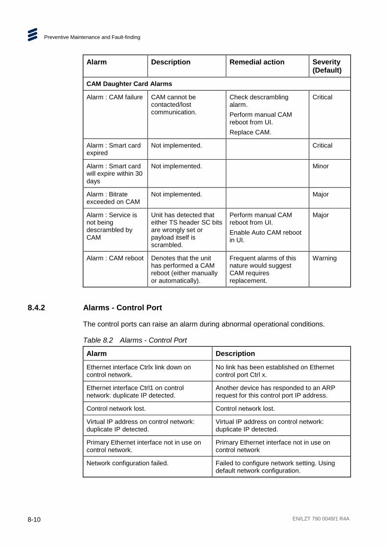
Preventive Maintenance and Fault-finding
8-10 EN/LZT 790 0049/1 R4A
Alarm Description Remedial action Severity (Default)
CAM Daughter Card Alarms
Alarm : CAM failure CAM cannot be contacted/lost communication.
Check descrambling alarm. Perform manual CAM reboot from UI. Replace CAM.
Critical
Alarm : Smart card expired
Not implemented. Critical
Alarm : Smart card will expire within 30 days
Not implemented. Minor
Alarm : Bitrate exceeded on CAM
Not implemented. Major
Alarm : Service is not being descrambled by CAM
Unit has detected that either TS header SC bits are wrongly set or payload itself is scrambled.
Perform manual CAM reboot from UI. Enable Auto CAM reboot in UI.
Major
Alarm : CAM reboot Denotes that the unit has performed a CAM reboot (either manually or automatically).
Frequent alarms of this nature would suggest CAM requires replacement.
Warning
8.4.2 Alarms - Control Port
The control ports can raise an alarm during abnormal operational conditions.
Table 8.2 Alarms - Control Port
Alarm Description
Ethernet interface Ctrlx link down on control network.
No link has been established on Ethernet control port Ctrl x.
Ethernet interface Ctrl1 on control network: duplicate IP detected.
Another device has responded to an ARP request for this control port IP address.
Control network lost. Control network lost.
Virtual IP address on control network: duplicate IP detected.
Virtual IP address on control network: duplicate IP detected.
Primary Ethernet interface not in use on control network.
Primary Ethernet interface not in use on control network
Network configuration failed. Failed to configure network setting. Using default network configuration.

Preventive Maintenance and Fault-finding
EN/LZT 790 0049/1 R4A 8-11
8.4.3 Alarms - Data Port
The data ports can raise an alarm during abnormal operational conditions.
Table 8.3 Alarms - Data Port
Alarm Description
Ethernet interface Data z link down in Data interface group x-y.
Data interface in data interface group x-y has gone down.
Ethernet interface data z in data interface group, x-y: duplicate IP detected.
Another device has responded to an ARP request for the IP address set for data z interface in data interface group x-y.
Virtual IP address on data interface group, x-y: duplicate IP detected.
The virtual IP address assigned to data interface group 1-2 or 3-4 is already in use.
Primary Ethernet interface not in use on data interface group x-y.
Primary interface is not in use in data interface group x-y or 3-4.
Data x: Duplicate IP Address. Duplicate IP address detected; Another device has responded to an ARP request for the IP address of this port.
Data interface group x-y: data network lost.
The connection with data interface group x-y has been lost.
Network configuration failed. Failed to configure network setting. Using default network configuration.
8.4.4 Alarms - Option Cards
The Option Card self-monitors for correct operation and correct any inconsistencies it finds. This includes the resetting of malfunctioning sub-systems or the whole card if necessary. The module attempts to maintain correct operation to minimize the effects of faults. All such actions are reported through the alarms/status/logging back to the Host Card.
The Host Card monitors all responses back from the module and resets the module if appropriate. This includes initiating redundancy switches if this results in limiting the error period. All actions are logged by the Host Card. All masking of alarms is handled by the Host Card.
The Option Cards provide the following alarms back to the Host Card:
• Loss of RF input.
• Excessive BER.
• Critical alarm (card has malfunctioned, internal log holds nature of failure).
• Over temperature (including a warning level as well as a critical level).
Preventive Maintenance and Fault-finding
8-12 EN/LZT 790 0049/1 R4A
8.5 Fault-finding
8.5.1 Fault-finding Philosophy
It is the objective of this section to provide sufficient information to enable you to rectify apparent faults or else to identify the suspect module, where possible. Some basic procedures are provided to follow in the event of a suspected failure. It is assumed that fault-finding has already been performed at a system level and that other equipment units have been eliminated as the possible cause of the failure.
Warning!
Do not remove the top cover of this equipment. Hazardous voltages are present within this equipment and may be exposed if the top cover is removed. Only Ericsson trained and approved service engineers are permitted to service this equipment.
Caution!
Do not remove the top cover of this equipment as this may invalidate any warranties. Unauthorised maintenance or the use of non-approved replacements may affect the equipment specification and invalidate any warranties.
This Reference Guide does not include any maintenance information or procedures that would require the removal of the top cover.
If the following information fails to clear the abnormal condition, call a Service Engineer or contact Customer Services using the information given in the preliminary pages of this Reference Guide.
8.5.2 Preliminary Checks
Always investigate the failure symptoms fully, prior to taking remedial action. Fault diagnosis for the equipment operator is limited to the following tasks, since the operator should NOT remove the covers of the equipment: 1. Check the front panel and web GUI alarm indications to specify the nature of the
fault. 2. Confirm that the equipment hardware configuration is suitable for the purpose
and has been correctly installed and connected (see Chapter 2, Installing the Equipment).
3. Confirm that inappropriate operator action is not causing the problem, and that the equipment software set-up is capable of performing the task being asked of it. If the validity of the configuration, set-up or operation is in doubt, check it (see Chapter 5, Web GUI Control).

Preventive Maintenance and Fault-finding
EN/LZT 790 0049/1 R4A 8-13
4. Check that the fans are unobstructed and working correctly.
When the failure condition has been fully investigated, and the symptoms are known, proceed with fault-finding according to the observed symptoms. If the fault persists, and cannot be rectified using the instructions given in this Reference Guide, contact Customer Services. Switch off the equipment if it becomes unusable, or to protect it from further damage.
8.5.3 Power Supply Problems/Unit Not Working
If the unit Status LED is unlit, fault-find the problem as detailed in Table 8.4.
Table 8.4 Power Supply Problems/Unit Not Working
Step Action If Result of Action is Yes…
If Result of Action is No…
1 Confirm Status LED. Is the unit working but the display inactive?
If the unit is clearly working normally then the front panel may be at fault. Call a Service Engineer.
Proceed to next step.
2 Check Power Source. Connect a known-working piece of equipment to the power source outlet. Does it work?
The problem lies within the unit or power cable. Proceed to next step.
The problem lies with the power source. Check building circuit breakers, fuse boxes, etc. If problem persists, contact the electricity supplier.
3 Check Power Cable and Fuse. Unplug the power connector from the unit and try it in another piece of equipment. Does it work?
The problem lies within the unit. Proceed to next step.
The problem lies with either the cable itself, or with the fuse in the plug. Replace the fuse or try to substitute another cable.
4 Check PSU Module(s) and Fuse(s). Ensure the power connector is unplugged. Remove the fuse from the rear panel connector and inspect it. Has the fuse blown?
Replace the fuse with one of the correct type and rating. If the PSU still does not work, unplug the power cable and call a Service Engineer.
Possible problem with the PSU module. Call a Service Engineer.
8.5.3.1 Fuse Replacement
Please refer to the Installation, Safety and Compliance Information for Ericsson Compression Products Reference Guide supplied with your product for full details of how to replace the fuse in your product.

Preventive Maintenance and Fault-finding
8-14 EN/LZT 790 0049/1 R4A
8.5.3.2 Lithium Battery
The lithium battery fitted within this product is not user replaceable and as such should only be replaced by qualified service personnel.
8.5.4 Fan(s) Not Working/Overheating
The unit is fitted with fans, all of which run continuously. The unit contains a temperature sensor that will highlight if there is a cooling problem. In the event of overheating problems, refer to Table 8.5.
Note: Failure to ensure a free air-flow around the unit may cause overheating. This condition is detected by a temperature sensor; it may be used to trigger an automatic alarm.
Warning!
The fans run at high speeds. DO NOT insert objects into the front of the unit when attempting to confirm fan rotation as this may result in injury or damage to the fans and the unit.
Table 8.5 Fans Not Working/Overheating
Step Action If Result of Action is Yes…
If Result of Action is No…
1 Check Fan Rotation. Inspect the fans located at the sides of the enclosure. Are the fans rotating? Check Base Board temperature and fan.
Check that the unit has been installed with sufficient space allowed for air-flow (see Chapter 2, Installing the Equipment). If the ambient air is too hot, additional cooling may be required.
Possible break in the DC supply from the PSU module to the suspect fan(s). Call a Service Engineer.

Preventive Maintenance and Fault-finding
EN/LZT 790 0049/1 R4A 8-15
8.5.5 Cannot Access Web GUI
In the event that you cannot access the web GUI, refer to Table 8.6.
Table 8.6 Cannot Access Web GUI
Step Action If Result of Action is Yes…
If Result of Action is No…
1 Check IP Connectivity. Ping the unit from another device on the same IP subnet using the device command prompt. Does the unit return the ping?
Ensure you are using an appropriate browser. See Chapter 5, Web GUI Control for details. Proceed to next step.
Check you have the correct IP address. See Cannot Ping the Unit, below.
2 Check other unit web GUIs or websites. Does the browser access other IP addresses?
There is a problem with the unit. Proceed to next step.
There is a problem with the computer you are using to access the network, or with the network.
3 Restart the Unit. Can you access the web GUI now?
Check your configuration. You may need to reload a saved configuration to restore your system.
Possible problem with the unit. Call a Service Engineer.
8.5.6 Communications (Control Port/Data Port) Alarms
The control ports can raise an alarm during abnormal operational conditions.
Table 8.7 Control Ports Alarms
Alarm Description
Ctrl x: Link Down No link has been established on this Ethernet Control Port.
Ctrl x: Duplicate Control IP Address Detected
Another device has responded to an ARP request for this Control port IP address.
The data ports can raise an alarm during abnormal operational conditions.
Table 8.8 Data Ports Alarms
Alarm Description
Data x: Link Down No link has been established on this Ethernet Data Port.
Data x: Duplicate IP Address
Duplicate IP Address Detected; Another device has responded to an ARP request for the IP address of this port.

Preventive Maintenance and Fault-finding
8-16 EN/LZT 790 0049/1 R4A
8.5.7 Cannot Ping the Unit
‘Pinging’ a computer is a way to check and see if a computer is on the network. Pings send a network request to a computer asking it to respond (ICMP ECHO_REQUEST).
To ping a computer from a Windows/PC machine, use the MSDOS prompt and type the command: ping <IP address>
A successful ‘ping’ consists of receiving back a copy of a short transmitted test message. The reply will display ‘ping statistics’ (number of packets sent and received and the time taken, in ms, to receive back those packets.
In the event that you cannot ping your unit, refer to Table 8.9.
Table 8.9 Cannot Ping the Unit
Step Action If Result of Action is Yes…
If Result of Action is No…
1 Check Connection at back of PC. Is the network connection connected and active?
Possible network or unit problem. Proceed to next step.
Change port/replace cable, if necessary, and check network settings.
2 Check Connection at back of unit. Is the network connection connected and active?
Possible network problem. Proceed to next step.
Change port/replace cable, if necessary, and check network settings.
3 Check network switch operation. Is the network switch connected and active?
Possible network problem. Proceed to next step.
Change port/replace cable/replace network switch, if necessary, and check network settings.
4 Check network operation. Ping other devices on the same IP subnet using the device command prompt. Can you ping other devices?
Network is operational. Possible unit problem. Call a Service Engineer.
Possible problem with IP switch, router or network. Contact your network administrator.
8.5.8 Configuration Problems
In the event that you have configuration problems, refer to Table 8.10.

Preventive Maintenance and Fault-finding
EN/LZT 790 0049/1 R4A 8-17
Table 8.10 Configuration Problems
Step Action If Result of Action is Yes…
If Result of Action is No…
1 Check configuration settings. Is your configuration workable?
Proceed to next step. Adjust settings, if necessary, using Services > Configure web page. Make sure to click the Apply button after making any changes.
2 Check Card health and allocation of resources. Have you got enough Cards fitted and operational?
Proceed to next step. Install more Cards or try re-allocating resources and re-check.
3 Check configuration file. Have you made any recent changes to the configuration?
Upload a backup (previously saved) configuration file, or upload one from another unit performing a similar function. If this fails to restore operation, call a Service Engineer.
8.6 SNMP Traps
8.6.1 What Is An SNMP Trap?
This feature enables a management station to be notified of significant events (including alarm events) by sending an SNMP message to a specified IP address. If you have a large number of devices, it may be impractical to poll or request information from every device. This feature enables each ‘agent’ on the managed device to notify the manager without solicitation. It does this by sending a message known as a ‘trap’ of the event.
When the SNMP trap is received, the management station displays it and the manager can choose to take an action based on the event, perhaps by polling the agent directly, or by polling other associated device agents to obtain a better understanding of the event. Trap-directed notification can result in substantial savings of network and agent resources by eliminating the need for numerous SNMP requests.
Simple Network Management Protocol (SNMP) is an application layer protocol that facilitates the exchange of management information between network devices. It is part of the Transmission Control Protocol/Internet Protocol (TCP/IP) protocol suite and is defined in a set of standards (RFC 1065 - RFC 1067, RFC 1155 - RFC 1157, RFC 1213, RFC 1441 - RFC 1452, RFC 1901 - RFC 1910, RFC 2576, RFC 3411 - RFC 3418) published by the Internet Engineering Task Force (IETF).

Preventive Maintenance and Fault-finding
8-18 EN/LZT 790 0049/1 R4A
8.6.2 Supported Protocols
SNMP versions 1, 2c and 3 are supported, primarily for alarm trap handling. The General Ericsson MIB is also supported.
Note: Unit does not support control via SNMP, all remote control is via HTTP or HTTPS.
8.6.3 Operation
The unit’s SNMP functionality can be enabled or disabled, with up to five IP addresses assigned for any SNMP Trap message to be sent. The default is 000.000.000.000, which causes the SNMP traps to be sent to the last SNMP master. The SNMP community name can also be set.
The user can control which SNMP traps are generated. The options are;
• Start Messages only.
• Fail and Start Messages only.
• All Traps.
8.6.4 SNMP Interface Parameters
Table 8.11 SNMP Interface Parameters
Parameter Description
SNMP Read Community
The SNMP community name for read access. default = public
SNMP Location Textual description of the location of the unit
SNMP Contact Name of the person responsible for this unit
SNMP Trap Community
The SNMP community name for read access. default = private
SNMP Trap Destination
The destination IP address for SNMP trap messages. Up to five destinations can be defined, but by default none are assigned
SNMP Trap Alarm Level
Defines what events trigger the generation of an SNMP trap message. The options are: Start Messages Only, i.e. only system start up events. Fail and Start Messages only, i.e. start-up events and critical alarms and All traps, i.e. start-up events and all alarms and warnings.

Preventive Maintenance and Fault-finding
EN/LZT 790 0049/1 R4A 8-19
8.7 Viewing Log Files The log file records the events on the unit. Extracted from the unit, the log file may contain important information that can facilitate tracking down problems.
The event log is stored on the Host Controller Card (HCC). A log file is generated with a file format as defined by RFC3164. Once the log has filled the space allocated to it, the oldest entries in the log file are overwritten.
Events that are logged include power-on, power on self test (POST) results, warning and alarm assertions and de-assertions, user log ins and log outs. Any changes to the time and date are also recorded in the system log. Each event has a UTC time and date stamp appended to it, with a time resolution of one second.
The various system log files are accessible from the web pages. The system log can be exported as a comma separated list, so that it is easy to import it in to a spreadsheet, where it can be easily filtered or sorted.
See Chapter 3, Getting Started for details of how to generate a log file.
8.8 Importing and Exporting Configurations Configuration-related problems may be fixed by importing a unit configuration from an earlier time. We recommend that you make a copy of your unit configuration whenever you make a major change to the unit configuration.
The current settings used by the unit can be exported as an file in XML format, which can then be saved on any digital media. This file can then be imported at a later date, if required, to restore your unit to a previous operational state.
See Chapter 3, Getting Started for details of how to import and export unit configurations.
8.9 Calling a Service Engineer If you cannot resolve a problem with your equipment using the information provided in this chapter, or if you experience technical or operational difficulties, please do not hesitate to contact us to request assistance.
There is a lot of information you can give us that will enable us to diagnose your problem swiftly. When contacting us please provide the following:
• Serial number. To obtain this see the front panel System > Versions screen or Device > Hardware web GUI page.
• Software version number. To obtain this see the front panel System > Versions screen or Device > Hardware web GUI page.

Preventive Maintenance and Fault-finding
8-20 EN/LZT 790 0049/1 R4A
• Configuration, both hardware and software. To obtain a copy of your current configuration, go to the Configure > Save-Load web page and obtain an XML file.
• Unit logs, if relevant. To obtain these, go to the Support > Import and Export web GUI page.
• System architecture and environment.
• Description of the symptoms and what diagnosis and tests have already been attempted.
• Any external events that may be related as triggers of the symptoms. If so, at what local time?
• Wireshark IP captures, if relevant.
• System logs from any controlling application software, if relevant.
In addition to the above, please do not forget to provide us with your contact details to enable us to get in touch with you swiftly:
• Name(s).
• Telephone and fax numbers.
• Email address.
• Business address.

EN/LZT 790 0049/1 R4A A-1
A Glossary Annex A
The following list covers most of the abbreviations, acronyms and terms as used in Ericsson Manuals, User and Reference Guides. All terms may not be included in this Reference Guide.
µm Micrometer (former name - micron): A unit of length equal to one
millionth (10-6) of a meter.
1000BaseT The term for the Electrical Gigabit Ethernet interface. This is the most common interface for Gigabit Ethernet. Most Gigabit-enabled PCs and equipment use this interface.
3:2 pull-down A technique used when converting film material (which operates at 24 pictures per second) to 525-line video (operating at 30 pictures per second).
4:2:0 Digital video coding method in which the color difference signals are sampled on alternate lines at half the luminance rate.
4:2:2 Digital video coding method in which the color difference signals are sampled on all lines at half the luminance rate.
422P@ML 422 Profile at Main Level: A subset of the MPEG-2 standard, which supports digital video storage (DVD etc.) and transmissions up to 50 Mbps over various mediums. Used for Contribution and Distribution applications.
ABR Adaptive Bit Rate.
ADPCM Adaptive Differential Pulse Code Modulation: An advanced PCM technique that converts analogue sound into digital data and vice versa. Instead of coding an absolute measurement at each sample point, it codes the difference between samples and can dynamically switch the coding scale to compensate for variations in amplitude and frequency.
ACC Authorization Control Computer.
ADT Audio, Data And Teletext.
AFC Automatic Frequency Control.
AFS Automation File Server.
AGC Automatic Gain Control.

Glossary
A-2 EN/LZT 790 0049/1 R4A
ALC Automatic Loudness Control: An audio processing mode for measuring and modifying audio amplitude with the aim of changing the perceived loudness level. It uses a measurement based upon the new standards for measuring audio loudness defined in ITU-R BS.1770-2, this standard forms the measurement basis of the guidelines in EBU R128 and ATSC/A85.
AMOL I and II Automatic Measure of Line-ups I and II: Used by automated equipment to measure programme-viewing ratings.
ARP Address Resolution Protocol. A protocol used to "resolve" IP addresses into underlying Ethernet MAC addresses.
ASI Asynchronous Serial Interface.
ASIC Application-Specific Integrated Circuit: A customized chip designed to perform a specific function.
Async Asynchronous.
ATM Asynchronous Transfer Mode: A connection orientated, cell based, data transport technology designed for Broadband ISDN (B-ISDN). It provides a circuit-switched bandwidth-on-demand carrier system, with the flexibility of packet switching. It offers low end-to-end delays and (negotiable on call set up) Quality of Service guarantees. Asynchronous refers to the sporadic nature of the data being transmitted. Cells are transmitted only when data is to be sent, therefore the time interval between cells varies according to the availability of data.
ATSC Advanced Television Standards Committee: An organization founded in 1983 to research and develop a digital TV standard for the U.S.A. In late 1996, the FCC adopted the ATSC standard, the digital counterpart of the NTSC standard.
AVP Advanced Video Processor.
B3ZS Bipolar with Three Zero Substitution: A method of eliminating long zero strings in a transmission. It is used to ensure a sufficient number of transitions to maintain system synchronization when the user data stream contains an insufficient number of 1s to do so. B3ZS is the North American equivalent of the European HDB3.
Backward Compatibility
Refers to hardware or software that is compatible with earlier versions.
BAT Bouquet Association Table: Part of the service information data. The BAT provides information about bouquets. It gives the name of the bouquet and a list of associated services.
baud rate The rate of transfer of digital data when the data comprises information symbols that may consist of a number of possible states. Equivalent to bit rate when the symbols only have two states (1 and 0). Measured in Baud.
BER Bit Error Ratio: A measure of transmission quality. The rate at which errors occur in the transmission of data bits over a link. It is generally shown as a negative exponent, (e.g., 10-7 means that 1 in 10,000,000 bits are in error).

Glossary
EN/LZT 790 0049/1 R4A A-3
BISS Basic Interoperable Scrambling System: Non-proprietary encryption from EBU (Tech3290).
Bit rate The rate of transfer of digital data when the data comprises two logic states, 1 and 0. Measured in bit/s.
Block; Pixel Block An 8-row by 8-column matrix of luminance sample values, or 64 DCT coefficients (source, quantized, or de-quantized).
Bouquet A collection of services (TV, radio, and data, or any combination of the three) grouped and sold together, and identified in the SI as a group. A single service may be in several bouquets.
B-Picture; B-Frame Bi-directionally Predictive Coded Picture/Frame: A picture that is coded using motion-compensated prediction from previous I or P frames (forward prediction) and/or future I or P frames (backward prediction). B frames are not used in any prediction.
BPSK Binary Phase Shift Keying: A data modulation technique.
Buffer A memory store used to provide a consistent rate of data flow.
BW Bandwidth: The transmission capacity of an electronic line such as (among others) a communications network, computer bus, or broadcast link. It is expressed in bits per second, bytes per second or in Hertz (cycles per second). When expressed in Hertz, the frequency may be a greater number than the actual bits per second, because the bandwidth is the difference between the lowest and highest frequencies transmitted. High bandwidth allows fast transmission or high-volume transmission.
Byte-mode Each byte is delivered separately in the ASI transport stream, with stuffing data added between the Bytes to increase the data rate to 270 Mbps. See DVB Document A010 rev. 1, Section B3.3, (ASI) Layer-2 Transport Protocol.
CA Conditional Access: The technology used to control the access to viewing services to authorized subscribers through the transmission of encrypted signals and the programmable regulation of their decryption by a system such as viewing cards.
CAT Conditional Access Table: Part of the MPEG-2 Program Specific Information (PSI) data. Mandatory for MPEG-2 compliance if CA is in use.
C-Band The portion of the electromagnetic spectrum, which spans the frequency range of approximately 4 GHz to 6 GHz. Used by communications satellites. Preferred in tropical climates because it is not susceptible to fading.
CCIR See: ITU-R.
CCITT See: ITU-T.
Channel a narrow range of frequencies, part of a frequency band, for the transmission of radio and television signals without interference from other channels. In the case of OFDM, a large number of carriers spaced apart at precise frequencies are allocated to a channel.

Glossary
A-4 EN/LZT 790 0049/1 R4A
Channel Coding A way of encoding data in a communications channel that adds patterns of redundancy into the transmission path in order to improve the error rate. Such methods are widely used in wireless communications.
Chrominance The color part of a TV picture signal, relating to the hue and saturation but not to the luminance (brightness) of the signal. In a composite-coded color system, the color information (chrominance, often referred to as chroma) is modulated onto a high frequency carrier and added to the monochrome-format video signal carrying the luminance (Y). In a component-coded color system, the two color-difference signals (R-Y)(B-Y) usually referred to as CRCB
(digital) or PRPB (analogue), are used to convey color information. When CRCB (PRPB) is added to the luminance (Y), the complete picture information is conveyed as YCRCB (YPRPB).
Closed Captioning A TV picture subtitling system used with 525-line analogue transmissions.
CODE Create Once Distribute Everywhere.
Codec The combination of an Encoder and a complementary Decoder located respectively at the input and output of a transmission path.
COFDM Coded OFDM: COFDM adds forward error correction to the OFDM transmission consisting of Reed-Solomon (RS) coding followed by convolutional coding to add extra bits to the transmitted signal. This allows a large number of errors at the receive end to be corrected by convolutional (Viterbi) decoding followed by RS decoding.
Composite CVBS Video Signal, 1 V pk-pk
Compression Reduction in the number of bits used to represent the same information. For the purposes of a broadcast system, it is the process of reducing digital picture information by discarding redundant portions of information that are not required when reconstituting the picture to produce viewing clarity. Compression allows a higher bite-rate to be transmitted through a given bandwidth.
Compression System
Responsible for compressing and multiplexing the video / audio / data bitstreams, together with the authorization stream. The multiplexed data stream is then ready for transmission.
CRCB Digital Color difference signals. These signals, in combination with the luminance signal (Y), define the color and brightness of each picture element (pixel) on a TV line. See: Chrominance
CRC Cyclic Redundancy Check: A mathematical algorithm that computes a numerical value based on the bits in a block of data. This number is transmitted with the data and the receiver uses this information and the same algorithm to ensure the accurate delivery of data by comparing the results of algorithm and the number received. If a mismatch occurs, an error in transmission is presumed.
CVBS Chroma Video Burst and Sync: An analogue Video SD resolution signal, such as NTSC or PAL.

Glossary
EN/LZT 790 0049/1 R4A A-5
dB Decibels: A ratio of one quantity to another using logarithmic scales to give results related to human aural or visual perception. dB is a ratio whereas dBm, for example, is an absolute value, quoted as a ratio to a fixed point of 0 dBm. 0 dBm is 1 mW at 1 kHz terminated in 600 Ω. 0 dBmV is 1 mV terminated in 75 Ω.
DCE Data Communications Equipment: Typically a modem. It establishes, maintains and terminates a session on a network but in itself is not the source (originator) or destination (end receiving unit) of signals (e.g. a computer, see DTE). A DCE device may also convert signals to comply with the transmission path (network) format.
DCT Discrete Cosine Transform: A technique for expressing a waveform as a weighted sum of cosines. Raw video data is not readily compressible. DCT is not in itself a compression technique but is used to process the video data so that it is compressible by an encoder. DCT processes the picture on an 8x8-pixel block basis, converting the data from an uncompressible X Y form (as displayed by an oscilloscope) to a compressible frequency domain form (as displayed by a spectrum analyzer). Can be forward DCT or inverse DCT.
DDS Direct Digital Synthesiser.
Decoder The unit containing the electronic circuitry necessary to decode encrypted signals. Some Decoders are separate from the receiver but in satellite TV broadcasting, the term is often used interchangeably as a name for an Integrated Receiver Decoder (IRD). The term IRD, or IRD / Decoder, is usually associated with satellite TV broadcasting while Cable systems are based on Converters or on Set-Top Boxes / Converters.
Decoding Time stamp
A field that may be present in a PES packet header that indicates the time that an access unit is to be decoded in the system target Decoder.
DENG Digital Electronic News Gathering
DID Data Identifier.
Differential Coding Method of coding using the difference between the value of a sample and a predicted value.
DiffServ Differentiated Services. A mechanism used on layer 3 - e.g. the IP layer - to differentiate between traffic of various types. DiffServ is based on the ToS field and provides a mechanism for the network to give e.g. video traffic higher priority than other traffic (for example Internet traffic).
DIL Dual In Line: The most common type of package for small and medium scale integrated circuits. The pins hang vertically from the two long sides of the rectangular package, spaced at intervals of 0.1 inch.
DIN Deutsches Institut für Normung: German Standards Institute.
Downlink The part of the satellite communications circuit that extends from the satellite to an Earth station.

Glossary
A-6 EN/LZT 790 0049/1 R4A
Downconvert The process by which the frequency of a broadcast transport stream is shifted to a lower frequency range.
DPCM Differential Pulse Code Modulation: An audio digitization technique that codes the difference between samples rather than coding an absolute measurement at each sample point.
DSNG Digital Satellite News-Gathering.
DSP Digital Signal Processor.
DTE Data circuit Terminating Equipment: A communications device that originates (is the source) or is the end receiving unit (destination) of signals on a network. It is typically a terminal or computer.
DTH Direct-To-Home. The term used to describe uninterrupted transmission from the satellite directly to the subscriber, that is, no intermediary cable or terrestrial network utilized.
DTMF Dual-Tone MultiFrequency
DVB Digital Video Broadcasting: A European project which has defined transmission standards for digital broadcasting systems using satellite (DVB-S), cable (DVB-C) and terrestrial (DVB-T) medium, created by the EP-DVB group and approved by the ITU. Specifies modulation, error correction, etc. (see EN 300 421 for satellite, EN 300 429 for cable and EN 300 744 for terrestrial).
DVB SI Digital Video Broadcasting Service Information.
DVB-PI DVB-Professional Interfaces
DWDM Dense Wavelength Division Multiplexing. A mechanism to utilize existing fiber with even more bandwidth by adding extra signals using other wavelengths/colors
Earth Technical Earth: Ensures that all equipment chassis within a rack are at the same potential, usually by connecting a wire between the Technical earth terminal and a suitable point on the rack. This is sometimes known as a Functional earth. Protective Earth: Used for electric shock protection. This is sometimes known as a safety earth.
EBU European Broadcast Union.
ECM Entitlement Control Message.
EDI Ethernet Data Input
EIA Electronics Industries Association (USA).
EIT Event Information Table: Equipment: A component of the DVB-Service Information (SI) stream generated within an Encoder, containing information about events or programmes such as event name, start time, duration, etc. System: EIT (Present/Following) contains the name of the current and next event. It may include an optional descriptor (synopsis) giving brief details of content. EIT (Schedule) is used to produce a full EPG. The EIT is the only DVB-SI table, which can be encrypted.
Elementary Stream A generic term for a coded bitstream, be it video, audio or other.

Glossary
EN/LZT 790 0049/1 R4A A-7
EMC Electromagnetic Compatibility.
EMM Entitlement Management Message.
Encryption Encoding of a transmission to prevent access without the appropriate decryption equipment and authorization.
EPG Electronic Programme Guide: On-screen programme listing using thumbnail pictures and/or text.
Ethernet The most widely used local area network (LAN) defined by the IEEE as the 802.3 standard. Transmission speeds vary according to the configuration. Ethernet uses copper or fiber-optic cables.
ETS European Telecommunications Standard.
ETSI European Telecommunications Standards Institute.
FBAS German for CVBS
FCC Federal Communications Commission.
FDM Frequency Division Multiplex: A common communication channel for a number of signals, each with its own allotted frequency.
FEC Forward Error Correction: A method of catching errors in a transmission. The data is processed through an algorithm that adds extra bits and sends these with the transmitted data. The extra bits are then used at the receiving end to check the accuracy of the transmission and correct any errors.
FFT Fast Fourier Transformation: A fast algorithm for performing a discrete Fourier transform.
FIFO First In, First Out: A data structure or hardware buffer from which items are taken out in the same order they were put in. Also known as a shelf from the analogy with pushing items onto one end of a shelf so that they fall off the other. A FIFO is useful for buffering a stream of data between a sender and receiver that are not synchronized - i.e. they not sending and receiving at exactly the same rate.
FM Frequency Modulation: Analogue modulation procedure
Footprint The area of the Earth’s surface covered by a satellite’s downlink transmission. Also (generally) the area from which the satellite can receive uplink transmissions.
FTP File Transfer Protocol: A protocol used to transfer files over a TCP/IP network (Internet, UNIX, etc.). For example, after developing the HTML pages for a Web site on a local machine, they are typically uploaded to the Web server, using FTP. Unlike e-mail programs in which graphics and program files have to be attached, FTP is designed to handle binary files directly and does not add the overhead of encoding and decoding the data.
G.703 The ITU-T standard which defines the physical and electrical characteristics of hierarchical digital interfaces.

Glossary
A-8 EN/LZT 790 0049/1 R4A
GOP Group of Pictures: MPEG video compression works more effectively by processing a number of video frames as a block. The Ericsson AB Encoder normally uses a 12 frame GOP; every twelfth frame is an I frame.
GUI Graphical User Interface: The use of pictures rather than just words to represent the input and output of a program. A program with a GUI runs under a windowing system and has a screen interface capable of displaying graphics in the form of icons, drop-down menus and a movable pointer. The on-screen information is usually controlled / manipulated by a mouse or keyboard.
HDTV High Definition Television.
HPA High Power Amplifier: Used in the signal path to amplify the modulated and up-converted broadcast signal for feeding to the uplink antenna.
HSYNC Horizontal (line) SYNCs.
HTTP HyperText Transfer Protocol. The fundamental protocol used on the Internet for transmission of WEB pages and other data between servers and PCs
HU Height Unit
Hub A device in a multi-point network at which branch nodes interconnect.
ICAM Integrated Conditional Access Module: Embedded in the IRD and responsible for descrambling, plus packet filtering and reception. It also contains the physical interface to the subscriber’s viewing card.
ICMP Internet Control Message Protocol. ICMP messages, delivered in IP packets, are used for out-of-band messages related to network operation or mis-operation
IGMP Internet Group Management Protocol. IGMP is a protocol used to manage multicasts on the Internet. For a host (receiver unit) to receive a multicast, it needs to transmit IGMP "join" messages on the right format. Three versions exist. IGMPv2 is common today but IGMPv3 is the next step.
IDU Indoor unit
IEC International Electrotechnical Committee.
IF Intermediate Frequency: Usually refers to the 70 MHz or 140 MHz output of the Modulator in cable, satellite and terrestrial transmission applications.
Interframe Coding Compression coding involving consecutive frames. When consecutive frames are compared, temporal redundancy is used to remove common elements (information) and arrive at difference information. MPEG-2 uses B and P frames, but since they are individually incomplete and relate to other adjacent frames, they cannot be edited independently.

Glossary
EN/LZT 790 0049/1 R4A A-9
Intraframe Coding Compression coding involving a single frame. Redundant information is removed on a per frame basis. All other frames are ignored. Coding of a macroblock or picture that uses information only from that macroblock or picture. Exploits spatial redundancy by using DCT to produce I frames; these are independent frames and can be edited.
IP Internet Protocol: The IP part of TCP/IP. IP implements the network layer (layer 3) of the protocol, which contains a network address and is used to route a message to a different network or sub-network. IP accepts packets from the layer 4 transport protocol (TCP or UDP), adds its own header to it and delivers a datagram to the layer 2 data link protocol. It may also break the packet into fragments to support the Maximum Transmission / Transfer Unit (MTU) of the network.
I-picture; I-frame Intracoded Picture/Frame: A picture / frame, which is coded using purely intracoding with reference to no other field or frame information. The I frame is used as a reference for other compression methods.
IPPV Impulse Pay Per View: One-time events, purchased at home (on impulse) using a prearranged SMS credit line.
IRD Integrated Receiver Decoder: The Receiver with an internal MPEG Decoder, which is connected to the subscriber’s TV. The IRD is responsible for receiving and de-multiplexing all signals. The unit receives the incoming signal and if CA is active, decodes the signal when provided with a control word by the viewing card. Domestic IRDs are also known as Set-Top Units or Set-Top Boxes.
IRE Institute of Radio Engineers: No longer in existence but the name lives on as a unit of video amplitude measurement. This unit is 1% of the range between blanking and peak white for a standard amplitude signal.
ISDN Integrated Services Digital Network: The basic ISDN service is BRI (Basic Rate Interface), which is made up of two 64 kbps B channels and one 16 kbps D channel (2B+D). If both channels are combined into one, called bonding, the total data rate becomes 128 kbps and is four and a half times the bandwidth of a V.34 modem (28.8 kbps). The ISDN high speed service is PRI (Primary Rate Interface). It provides 23 B channels and one 64 kbps D channel (23B+D), which is equivalent to the 24 channels of a T1 line. When several channels are bonded together, high data rates can be achieved. For example, it is common to bond six channels for quality videoconferencing at 384 kbps. In Europe, PRI includes 30 B channels and one D channel, equivalent to an E1 line.
ISO International Standards Organisation.
ISOG Inter-union Satellite Operations Group.
ITS Insertion Test Signal: A suite of analogue test signals placed on lines in the VBI. Also known as VITS.
ITT Invitation To Tender.
ITU-R International Telecommunications Union - Radiocommunications Study Groups (was CCIR).
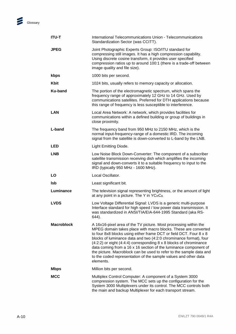
Glossary
A-10 EN/LZT 790 0049/1 R4A
ITU-T International Telecommunications Union - Telecommunications Standardization Sector (was CCITT).
JPEG Joint Photographic Experts Group: ISO/ITU standard for compressing still images. It has a high compression capability. Using discrete cosine transform, it provides user specified compression ratios up to around 100:1 (there is a trade-off between image quality and file size).
kbps 1000 bits per second.
Kbit 1024 bits, usually refers to memory capacity or allocation.
Ku-band The portion of the electromagnetic spectrum, which spans the frequency range of approximately 12 GHz to 14 GHz. Used by communications satellites. Preferred for DTH applications because this range of frequency is less susceptible to interference.
LAN Local Area Network: A network, which provides facilities for communications within a defined building or group of buildings in close proximity.
L-band The frequency band from 950 MHz to 2150 MHz, which is the normal input-frequency-range of a domestic IRD. The incoming signal from the satellite is down-converted to L-band by the LNB.
LED Light Emitting Diode.
LNB Low Noise Block Down-Converter: The component of a subscriber satellite transmission receiving dish which amplifies the incoming signal and down-converts it to a suitable frequency to input to the IRD (typically 950 MHz - 1600 MHz).
LO Local Oscillator.
lsb Least significant bit.
Luminance The television signal representing brightness, or the amount of light at any point in a picture. The Y in YCRCB.
LVDS Low Voltage Differential Signal: LVDS is a generic multi-purpose Interface standard for high speed / low power data transmission. It was standardized in ANSI/TIA/EIA-644-1995 Standard (aka RS-644).
Macroblock A 16x16-pixel area of the TV picture. Most processing within the MPEG domain takes place with macro blocks. These are converted to four 8x8 blocks using either frame DCT or field DCT. Four 8 x 8 blocks of luminance data and two (4:2:0 chrominance format), four (4:2:2) or eight (4:4:4) corresponding 8 x 8 blocks of chrominance data coming from a 16 x 16 section of the luminance component of the picture. Macroblock can be used to refer to the sample data and to the coded representation of the sample values and other data elements.
Mbps Million bits per second.
MCC Multiplex Control Computer: A component of a System 3000 compression system. The MCC sets up the configuration for the System 3000 Multiplexers under its control. The MCC controls both the main and backup Multiplexer for each transport stream.

Glossary
EN/LZT 790 0049/1 R4A A-11
MCPC Multiple Channels Per Carrier.
Meta-data Meta-data is descriptive data that is "tagged" to a movie or audio clip. Meta-data is essential for the broadcaster.
MMDS Multichannel Microwave Distribution System: A terrestrial microwave direct-to-home broadcast transmission system.
Motion Compensation
The use of motion vectors to improve the efficiency of the prediction of sample values. The prediction uses motion vectors to provide offsets into the past and/or future reference frames or fields containing previously decoded sample values that are used to form the prediction error signal.
Motion Estimation The process of estimating motion vectors in the encoding process.
Motion Vector A two-dimensional vector used for motion compensation that provides an offset from the coordinate position in the current picture or field to the coordinates in a reference frame or field.
MP@ML Main Profile at Main Level: A subset of the MPEG-2 standard, which supports digital video storage (DVD etc.) and transmissions up to 15 Mbps over various mediums.
MP@HL Main Profile at High Level: A subset of the MPEG-2 standard, which supports digital video storage (DVD etc.) and transmissions up to 80 Mbps over various mediums.
MPEG Moving Pictures Experts Group: The name of the ISO/IEC working group which sets up the international standards for digital television source coding.
MPEG-2 Industry standard for video and audio source coding using compression and multiplexing techniques to minimize video signal bit rate in preparation for broadcasting. Specified in ISO/IEC 13818. The standard is split into layers and profiles defining bit rates and picture resolutions.
MPLS Multi-protocol Label Switching. A Quality of Service mechanism for IP networks that allow IP packets to flow along a predefined path in a network, improving the reliability and robustness of the transmission.
MPM Media Processing Module.
MPTS Multi-Program Transport Streams. Transport Streams that carry multiple TV/Radio services.
msb Most significant bit.
Msymbol/s (Msym/s) Mega (million) Symbols per second (106 Symbols per second).
Multiplex A number of discrete data streams (typically 8 to 12), from encoders, that are compressed together in a single DVB compliant transport stream for delivery to a Modulator.

Glossary
A-12 EN/LZT 790 0049/1 R4A
Multicast An IP mechanism that allows transmission of data to multiple receivers. A multicast can also have several transmit sources simultaneously. In video applications, multicast is typically used to distribute a video signal from a central source to multiple destinations.
MUSICAM Masking pattern adapted Universal Sub-band Integrated Coding And Multiplexing: An audio bit rate reduction system relying on sub-band coding and psychoacoustic masking.
Mux Multiplexer: Transmission Multiplexer: receives EMMs from the ACC, ECMs from the BCC, video/audio data from the encoders, and the SI stream from the SIC. It then multiplexes them all into a single DVB-compliant transport stream, and delivers the signal to the uplink after modulation. The Multiplexer also contains the cipher card, which scrambles the services according to the control words supplied by the BCC.
Network In the context of broadcasting: a collection of MPEG-2 transport stream multiplexes transmitted on a single delivery system, for example, all digital channels on a specific cable system.
NICAM Near Instantaneously Companded Audio Multiplex: Official name is NICAM 728. Used for digital stereo sound broadcasting in the UK employing compression techniques to deliver very near CD quality audio. 728 refers to the bit rate in kbps.
NIT Network Information Table: Part of the service information data. The NIT provides information about the physical organization of each transport stream multiplex, and the characteristics of the network itself (such as the actual frequencies and modulation being used).
nm Nanometer: a unit of length equal to one thousand millionth (10-9) of a meter.
NMS Network Management System. A system used to supervise elements in an IP network. When a device reports an alarm, the alarm will be collected by the NMS and reported to the operator. NMS systems typically collect valuable statistics information about the network performance and can warn the operator early.
NTSC National Television Systems Committee: The group, which developed analogue standards used in television broadcast systems in the United States. Also adopted in other countries (e.g. Mexico, Canada, Japan). This system uses 525 picture lines and a 59.97 Hz field frequency.
NVOD Near Video On-Demand: Method of offering multiple showings of movies or events. The showings are timed to start at set intervals, determined by the broadcaster. Each showing of a movie or event can be sold to subscribers separately.
NVRAM Non-volatile Random Access Memory: Memory devices (permitting random read / write access) that do not lose their information when power is removed. Stores the default configuration parameters set by the user.
ODU Outdoor Unit

Glossary
EN/LZT 790 0049/1 R4A A-13
OFDM Orthogonal Frequency Division Multiplex: A modulation technique used for digital TV transmission in Europe, Japan and Australia; more spectrally efficient than FDM. In OFDM, data is distributed over a large number of carriers spaced apart at precise frequencies. The carriers are arranged with overlapping sidebands in such a way that the signals can be received without adjacent channel interference.
OPPV Order ahead Pay Per View: An advance purchase of encrypted one-time events with an expiry date.
OSD On-screen display: Messages and graphics, typically originating from the SMS, and displayed on the subscriber’s TV screen by the IRD, to inform the subscriber of problems or instruct the subscriber to contact the SMS.
Packet A unit of data transmitted over a packet switching network. A packet consists of a header followed by a number of contiguous bytes from an elementary data stream.
PAL Phase Alternating Line: A color TV broadcasting system where the phase of the R-Y color-difference signal is inverted on every alternate line to average out errors providing consistent color reproduction.
PAT Program Association Table: Part of the MPEG-2 Program Specific Information (PSI) data and is mandatory for MPEG-2 compliance. The PAT points (maps) to the PMT.
PCM Pulse Code Modulation: A process in which a signal is sampled, each sample is quantized independently of other samples, and the resulting succession of quantized values is encoded into a digital signal.
PCR Program Clock Reference: A time stamp in the transport stream from which the Decoder timing is derived.
PDC Program Delivery Control: A Teletext service allowing simple programming (i.e. VideoPlus) of VCR recording times. If the desired program is rescheduled, PDC updates the programming information in the VCR.
Pel Picture Element: Also known as a pixel. The smallest resolvable rectangular area of an image either on a screen or stored in memory. On-screen, pixels are made up of one or more dots of color. Monochrome and grey-scale systems use one dot per pixel. For grey-scale, the pixel is energized with different intensities, creating a range from dark to light (a scale of 0-255 for an eight-bit pixel). Color systems use a red, green and blue dot per pixel, each of which is energized to different intensities, creating a range of colors perceived as the mixture of these dots. If all three dots are dark, the result is black. If all three dots are bright, the result is white.
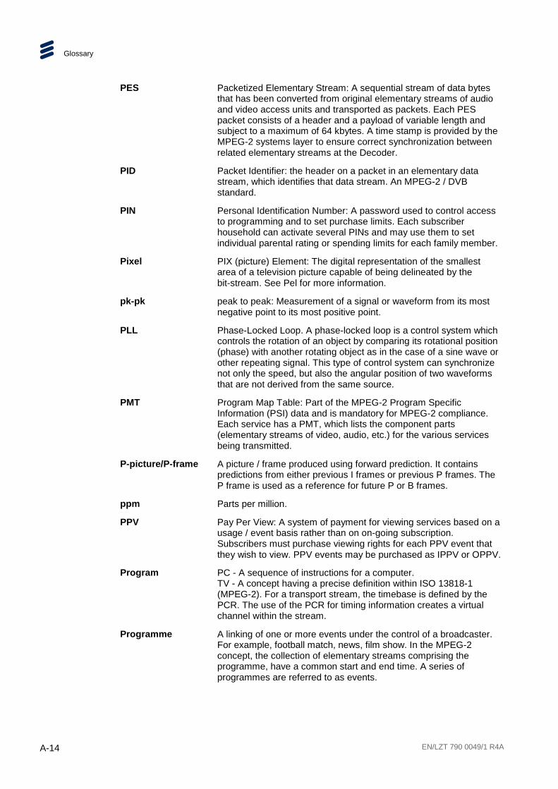
Glossary
A-14 EN/LZT 790 0049/1 R4A
PES Packetized Elementary Stream: A sequential stream of data bytes that has been converted from original elementary streams of audio and video access units and transported as packets. Each PES packet consists of a header and a payload of variable length and subject to a maximum of 64 kbytes. A time stamp is provided by the MPEG-2 systems layer to ensure correct synchronization between related elementary streams at the Decoder.
PID Packet Identifier: the header on a packet in an elementary data stream, which identifies that data stream. An MPEG-2 / DVB standard.
PIN Personal Identification Number: A password used to control access to programming and to set purchase limits. Each subscriber household can activate several PINs and may use them to set individual parental rating or spending limits for each family member.
Pixel PIX (picture) Element: The digital representation of the smallest area of a television picture capable of being delineated by the bit-stream. See Pel for more information.
pk-pk peak to peak: Measurement of a signal or waveform from its most negative point to its most positive point.
PLL Phase-Locked Loop. A phase-locked loop is a control system which controls the rotation of an object by comparing its rotational position (phase) with another rotating object as in the case of a sine wave or other repeating signal. This type of control system can synchronize not only the speed, but also the angular position of two waveforms that are not derived from the same source.
PMT Program Map Table: Part of the MPEG-2 Program Specific Information (PSI) data and is mandatory for MPEG-2 compliance. Each service has a PMT, which lists the component parts (elementary streams of video, audio, etc.) for the various services being transmitted.
P-picture/P-frame A picture / frame produced using forward prediction. It contains predictions from either previous I frames or previous P frames. The P frame is used as a reference for future P or B frames.
ppm Parts per million.
PPV Pay Per View: A system of payment for viewing services based on a usage / event basis rather than on on-going subscription. Subscribers must purchase viewing rights for each PPV event that they wish to view. PPV events may be purchased as IPPV or OPPV.
Program PC - A sequence of instructions for a computer. TV - A concept having a precise definition within ISO 13818-1 (MPEG-2). For a transport stream, the timebase is defined by the PCR. The use of the PCR for timing information creates a virtual channel within the stream.
Programme A linking of one or more events under the control of a broadcaster. For example, football match, news, film show. In the MPEG-2 concept, the collection of elementary streams comprising the programme, have a common start and end time. A series of programmes are referred to as events.

Glossary
EN/LZT 790 0049/1 R4A A-15
PRPB Analogue Color difference signals. Refer to CRCB for an explanation.
PS Program Stream: A combination of one or more PESs with a common timebase.
PSI Program Specific Information: Consists of normative data, which is necessary for the de-multiplexing of transport streams and the successful regeneration of programs (see also: SI).
PSIP Program System Information Protocol: The ATSC equivalent of SI for DVB.
PSK Phase Shift Keying: A method of modulating digital signals particularly suited to satellite transmission.
PSR Professional Satellite Receiver: See also: IRD.
PSU Power Supply Unit.
QAM Quadrature Amplitude Modulation: A method of modulating digital signals, which uses combined techniques of phase modulation and amplitude modulation. It is particularly suited to cable networks.
QoS Quality of Service. A common term for a set of parameters describing the quality you get from an IP network: Throughput, availability, delay, jitter and packet loss.
QPSK Quadrature Phase Shift Keying: A form of phase shift keying modulation using four states.
QSIF Quarter Screen Image Format.
Quantise A process of converting analogue waveforms to digital information. 8-bit quantization as set out in ITU-R Rec. 601. Uses 256 levels in the range 0 – 255 to determine the analogue waveform value at any given point. The value is then converted to a digital number for processing in the digital domain.
RAM Random Access Memory: A volatile storage device for digital data. Data may be written to, or read from, the device as often as required. When power is removed, the data it contains is lost.
RAS Remote Authorization System: An Ericsson AB proprietary public-key encryption system used to prevent unauthorized viewing of a TV programme or programmes.
Reflex™ An Ericsson AB proprietary system to provide efficient use of bandwidth by a set of encoders without sacrificing picture quality. A group bit rate is allocated to a set of Encoders and the bit rate for each encoder is allocated according to the requirements of the picture encoding process. The bit rate allocation can be performed externally by a multiplexer, or internally in a unit fitted with multiple VCM’s.
RF Radio Frequency.
RGB Red, Green, Blue: The Chroma information in a video signal.
RIP2 Routing Information Protocol v2. A protocol used between network routers to exchange routing tables and information.

Glossary
A-16 EN/LZT 790 0049/1 R4A
ROM Read Only Memory: A non-volatile storage device for digital data. Data has been stored permanently in this device. No further information may be stored (written) there and the data it holds cannot be erased. Data may be read as often as required.
RS Reed-Solomon coding: An error detection and correction, coding system. 16 bytes of Reed-Solomon Forward Error Correction code are appended to the packet before transmission bringing the packet length to 204 bytes. The 16 bytes are used at the receiving end to correct any errors. Up to eight corrupted bytes can be corrected.
RSVP ReSerVation Protocol. A Quality-of-service oriented protocol used by network elements to reserve capacity in an IP network before a transmission takes place.
RTP Real-time Transfer Protocol. A protocol designed for transmission of real-time data like video and audio over IP networks. RTP is used for most video over IP transmissions.
RLC Run Length Coding: Minimization of the length of a bit-stream by replacing repeated characters with an instruction of the form ‘repeat character x y times’.
SBR Spectral Band Replication.
SCPC Single Channel Per Carrier.
Spectral Scrambling
A process (in digital transmission) used to combine a digital signal with a pseudo-random sequence, producing a randomized digital signal that conveys the original information in a form optimized for a broadcast channel.
Scrambling Alteration of the characteristics of a television signal in order to prevent unauthorized reception of the information in clear form.
SDI Serial Digital Interface.
SDT Service Description Table: Provides information in the SI stream about the services in the system; for example, the name of the service, the service provider, etc.
SDTI Serial Data Transport Interface. A mechanism that allows transmission of various types of data over an SDI signal. This may be one or more compressed video signals or other proprietary data types. The advantage of SDTI is that existing SDI transmission infrastructure can be used to transport other types of data.
SELV Safety Extra Low Voltage (EN 60950).
SFP Small Form-factor Pluggable module. A standardized mechanism to allow usage of various optical interfaces for Gigabit Ethernet. Several types of SFP modules exist: Single-mode fiber modules for long-distance transmission and multi-mode fiber modules for shorter distances. SFP is also known as "mini-GBIC".
SIP Session Initiation Protocol. A common acronym for the ongoing effort to standardize signaling over IP networks, i.e. connection set-up and tear-down. SIP makes it possible to "dial" a remote receiver of data and set-up the connection in this way.

Glossary
EN/LZT 790 0049/1 R4A A-17
STB Set-Top Box: A box that sits on top of a television set and is the interface between the home television and the cable TV company. New technologies evolving for set-top boxes are video-on-demand, video games, educational services, database searches, and home shopping. The cable equivalent of the IRD.
SFN Single Frequency Network: The SFN technique allows large geographic areas to be served with a common transmission multiplex. All transmitters in the network are synchronously modulated with the same signal and they all radiate on the same frequency. Due to the multi-path capability of the multi-carrier transmission system (COFDM), signals from several transmitters arriving at a receiving antenna may contribute constructively to the total wanted signal. The SFN technique is not only frequency efficient but also power efficient because fades in the field strength of one transmitter may be filled by another transmitter.
SI Service Information: Digital information describing the delivery system, content and scheduling (timing) of broadcast data streams. DVB-SI data provides information to enable the IRD to automatically demultiplex and decode the various streams of programmes within the multiplex. Specified in ISO/IEC 13818[1]. (DVB)
Single Packet Burst Mode
A burst of ASI bytes (either 188 or 204, depending on packet length) is contiguously grouped into an MPEG-2 transport stream packet. Stuffing data is added between the packets to increase the data rate to 270 Mbps. See DVB Document A010 rev. 1, Section B3.3, (ASI) Layer-2 Transport Protocol.
Smart Card A plastic card with a built-in microprocessor and memory used for identification, financial transactions or other authorizing data transfer. When inserted into a reader, data is transferred to and from the host machine or a central computer. It is more secure than a magnetic stripe card and it can be disabled if the wrong password is entered too many times. As a financial transaction card, it can be loaded with digital money and used in the same way as cash until the balance reaches zero. The file protocol is specific to its intended application.
SMATV Satellite Mast Antenna Television: A distribution system, which provides sound and television signals to the households of a building or group of buildings, typically used to refer to an apartment block.
SMPTE Society of Motion Picture and Television Engineers.
SMS Subscriber Management System: A system which handles the maintenance, billing, control and general supervision of subscribers to conditional access technology viewing services provided through cable and satellite broadcasting. An SMS can be an automatic (e.g. Syntellect) system where subscribers order entitlements by entering information via a telephone. Alternatively, an SMS can be a manual system, which requires subscribers to speak with an operator who then manually enters their entitlement requests. Some systems support multiple SMSs.
SNG Satellite News-Gathering.
SNMP Simple Network Management Protocol.

Glossary
A-18 EN/LZT 790 0049/1 R4A
SNTP Simple Network Time Protocol is an Internet protocol used to synchronize the clocks of computers to some time reference. It is a simplified version of the protocol NTP protocol which is too complicated for many systems.
Spatial Redundancy Information repetition due to areas of similar luminance and/or chrominance characteristics within a single frame. Removed using DCT and Quantization (Intra-Frame Coding).
SPI Synchronous Parallel Interface.
Statistical Redundancy
Data tables are used to assign fewer bits to the most commonly occurring events, thereby reducing the overall bit rate. Removed using Run Length Coding and Variable Length Coding.
TCP / IP Transmission Control Protocol/Internet Protocol: A set of communications protocols that may be used to connect different types of computers over networks.
TDM Time Division Multiplex: One common, communications channel carrying a number of signals, each with its own allotted time slot.
TDT Time and Date Table: Part of the DVB Service Information. The TDT gives information relating to the present time and date.
Temporal Redundancy
Information repetition due to areas of little or no movement between successive frames. Removed using motion estimation and compensation (Inter-Frame Coding).
Time stamp A term that indicates the time of a specific action such as the arrival of a byte or the presentation of a presentation unit.
TNS Temporal Noise Shaping.
TOT Time Offset Table: This optional SI table supports the use of local offsets as well as the UTC time/date combination. The purpose of the table is to list by country the current offset from UTC and the next expected change to that offset (to track when daylight saving occurs). The offset resolution is to within 1 minute over a range of ±12 hours from UTC.
Transport Stream A set of packetized elementary data streams and SI streams, which may comprise more than one programme, but with common synchronization and error protection. The data structure is defined in ISO/IEC 13818-1 [1] and is the basis of the ETSI Digital Video Broadcasting standards.
Transport Stream Packet Header
A data structure used to convey information about the transport stream payload.
TS Transport Stream.
TSDT Transport Stream Descriptor Table: A component of the MPEG-2 PSI data. This table describes which type of Transport stream it is in (i.e. DVB, ATSC etc.). It may also contain other descriptors.
TSP Transport Stream Processor.
U 44.45 mm (rack height standard).

Glossary
EN/LZT 790 0049/1 R4A A-19
UART Universal Asynchronous Receiver Transmitter: A device providing a serial interface for transmitting and receiving data.
UDP User Datagram Protocol. A protocol above the IP layer that provides port multiplexing in addition. In essence, you can transmit IP data packets to several receiving processes in the same unit/device.
Unicast Point-to-point connection, i.e. the "opposite" of multicast which is one to many (or many to many). In this mode, a transmit unit sends video data direct to a unique destination address.
Upconvert The process by which the frequency of a broadcast transport stream is shifted to a higher frequency range.
Uplink The part of the communications satellite circuit that extends from the Earth to the satellite.
UPS Uninterruptable Power Supply: A method of supplying backup power when the electrical power fails or drops to an unacceptable voltage level. Small UPS systems provide battery power for a few minutes; enough to power down the computer in an orderly manner. This is particularly important where write back cache is used. Write back cache is where modified data intended for the disk is temporarily stored in RAM and can be lost in the event of a power failure. Sophisticated systems are tied to electrical generators that can provide power for days. UPS systems typically provide surge suppression and may provide voltage regulation.
UTC Universal Time Coordinated: The Coordinated Universal Time and is synonymous with GMT Greenwich Mean Time (GMT).
VCM Video Compression Module.
VITC Vertical Interval Time Code.
VITS Vertical Interval Test Signal: See: ITS.
VLAN Virtual LAN, a network of units that behave as if they are connected to the same wire even though they may actually be physically located on different segments of a LAN.
VPS Video Programming System: A German precursor to PDC
WSS Wide Screen Switching: Data used in wide-screen analogue services, which enables a receiver to select the appropriate picture display mode.
WST World System Teletext: System B Teletext. Used in 625 line / 50 Hz television systems (ITU-R 653).
XLR Audio connector featuring three leads, two for signal and one for GND.
XML eXtensible Markup Language. A very common self-describing text-based data format. Used for many purposes: Meta-data, configuration files, documents, etc. The readability of the format has made it very popular and is now the fundament for many types of WEB services.

Glossary
A-20 EN/LZT 790 0049/1 R4A
XPO The name given to the second generation Ericsson standard for web pages and additional supporting interfaces.
Y (Luminance) Defines the brightness of a particular point on a TV line. The only signal required for black and white pictures.
Y/C Broadcast video with separate color, Y (luminance) and C (Chroma) (sometimes called S-Video).
YUV Y: Luminance component (Brightness), U and V: Chrominance (Color difference)
EN/LZT 790 0049/1 R4A B-1
B Technical Specification Annex B
Contents B.1 Control Ethernet Specification ............................................................ B-3 B.1.1 Control Ports ...................................................................................... B-3 B.1.2 IP Parameters .................................................................................... B-3 B.1.3 MAC Address ..................................................................................... B-3 B.2 Data Ethernet Specification ................................................................ B-3 B.2.1 Data Ports .......................................................................................... B-3 B.2.2 Data Port Parameters ......................................................................... B-4 B.2.3 IP Parameters .................................................................................... B-4 B.2.4 MAC Address ..................................................................................... B-4 B.3 Satellite Input...................................................................................... B-4 B.4 Conditional Access ............................................................................. B-6 B.5 Transport Stream Output .................................................................... B-6 B.6 Management ...................................................................................... B-7 B.7 Environmental .................................................................................... B-7
List of Tables Table B.1 IP Parameters (Control Port) .............................................................. B-3 Table B.2 IP Parameters (Data Port) .................................................................. B-4 Table B.3 Satellite Input...................................................................................... B-4 Table B.4 Conditional Access ............................................................................. B-6 Table B.5 Transport Stream Output .................................................................... B-6 Table B.6 Management ...................................................................................... B-7 Table B.7 Environmental .................................................................................... B-7

Technical Specification
B-2 EN/LZT 790 0049/1 R4A
BLANK

Technical Specification
EN/LZT 790 0049/1 R4A B-3
B.1 Control Ethernet Specification
B.1.1 Control Ports
The system has two Ethernet control ports that support IEEE 802.3 100BaseTX and 1000BaseT Ethernet protocols. The Control ports are accessible via RJ-45 connectors on the rear panel of the chassis and support IEEE 802.3u auto-negotiation and parallel detection. Also, the ports support Auto-MDIX.
See Chapter 2, Installing the Equipment for connector details.
B.1.2 IP Parameters
It is possible to configure the following IP parameters for the Control Port.
Table B.1 IP Parameters (Control Port)
Parameter Specification
IP Address xxx.xxx.xxx.xxx (Ipv4)
Network Mask xxx.xxx.xxx.xxx (Ipv4)
Gateway Address xxx.xxx.xxx.xxx (Ipv4)
Note: The front panel always provides a way of changing these settings to prevent all control interfaces being disabled.
B.1.3 MAC Address
The MAC address of each Ethernet Control port is read only and cannot be edited.
B.2 Data Ethernet Specification
B.2.1 Data Ports
The Ethernet Data ports support IEEE 802.3u auto-negotiation and parallel detection. The auto-negotiation function can be disabled to force the line speed to be either 100 Mbps or 1000 Mbps.
These ports support Auto-MDIX. This function can be disabled.
See Chapter 2, Installing the Equipment for connector details.

Technical Specification
B-4 EN/LZT 790 0049/1 R4A
B.2.2 Data Port Parameters
The transport streams output via the IP Outputs contain 188 byte long transport stream packets.
The time that a port has had a link established is recorded to an accuracy of ± 1 second, and the information made available to the user.
The Ethernet Data Ports always respond to ICMP Echo requests to any source IP address assigned to an output transport stream currently being transmitted on that port.
The Ethernet Data Ports respond to all ARP requests
There is hardware filtering of received packets (i.e. a hardware ‘firewall’) to protect the ports from malicious interference.
B.2.3 IP Parameters
It is possible to configure the following IP parameters for the Data Port.
Table B.2 IP Parameters (Data Port)
Parameter Specification
IP Address xxx.xxx.xxx.xxx (Ipv4)
Network Mask xxx.xxx.xxx.xxx (Ipv4)
Gateway Address xxx.xxx.xxx.xxx (Ipv4)
The default values for source IP address, subnet mask are those assigned to the ethernet port, or in the case of mirrored mode, those assigned to the primary IP port.
B.2.4 MAC Address
The MAC address of each Ethernet Data port is read only and cannot be edited.
B.3 Satellite Input The following parameters are supported for the Satellite and Descrambling Module.
Table B.3 Satellite Input
Item Specification
Safety status SELV
Connector designation L-Band Input
Connector type F-Type
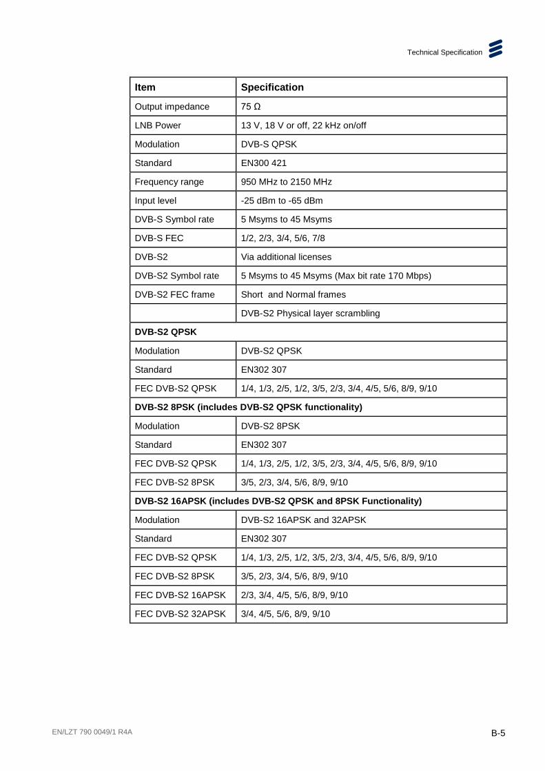
Technical Specification
EN/LZT 790 0049/1 R4A B-5
Item Specification
Output impedance 75 Ω
LNB Power 13 V, 18 V or off, 22 kHz on/off
Modulation DVB-S QPSK
Standard EN300 421
Frequency range 950 MHz to 2150 MHz
Input level -25 dBm to -65 dBm
DVB-S Symbol rate 5 Msyms to 45 Msyms
DVB-S FEC 1/2, 2/3, 3/4, 5/6, 7/8
DVB-S2 Via additional licenses
DVB-S2 Symbol rate 5 Msyms to 45 Msyms (Max bit rate 170 Mbps)
DVB-S2 FEC frame Short and Normal frames
DVB-S2 Physical layer scrambling
DVB-S2 QPSK
Modulation DVB-S2 QPSK
Standard EN302 307
FEC DVB-S2 QPSK 1/4, 1/3, 2/5, 1/2, 3/5, 2/3, 3/4, 4/5, 5/6, 8/9, 9/10
DVB-S2 8PSK (includes DVB-S2 QPSK functionality)
Modulation DVB-S2 8PSK
Standard EN302 307
FEC DVB-S2 QPSK 1/4, 1/3, 2/5, 1/2, 3/5, 2/3, 3/4, 4/5, 5/6, 8/9, 9/10
FEC DVB-S2 8PSK 3/5, 2/3, 3/4, 5/6, 8/9, 9/10
DVB-S2 16APSK (includes DVB-S2 QPSK and 8PSK Functionality)
Modulation DVB-S2 16APSK and 32APSK
Standard EN302 307
FEC DVB-S2 QPSK 1/4, 1/3, 2/5, 1/2, 3/5, 2/3, 3/4, 4/5, 5/6, 8/9, 9/10
FEC DVB-S2 8PSK 3/5, 2/3, 3/4, 5/6, 8/9, 9/10
FEC DVB-S2 16APSK 2/3, 3/4, 4/5, 5/6, 8/9, 9/10
FEC DVB-S2 32APSK 3/4, 4/5, 5/6, 8/9, 9/10
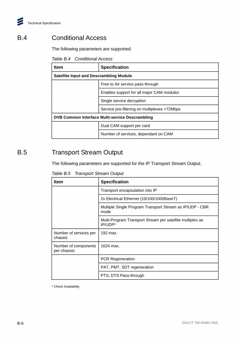
Technical Specification
B-6 EN/LZT 790 0049/1 R4A
B.4 Conditional Access The following parameters are supported.
Table B.4 Conditional Access
Item Specification
Satellite Input and Descrambling Module
Free to Air service pass-through
Enables support for all major CAM modules
Single service decryption
Service pre-filtering on multiplexes >72Mbps
DVB Common Interface Multi-service Descrambling
Dual CAM support per card
Number of services, dependant on CAM
B.5 Transport Stream Output The following parameters are supported for the IP Transport Stream Output.
Table B.5 Transport Stream Output
Item Specification
Transport encapsulation into IP
2x Electrical Ethernet (10/100/1000BaseT)
Multiple Single Program Transport Stream as IP/UDP - CBR mode
Multi-Program Transport Stream per satellite multiplex as IP/UDP*
Number of services per chassis
192 max.
Number of components per chassis:
1024 max.
PCR Regeneration
PAT, PMT, SDT regeneration
PTS, DTS Pass-through
* Check Availability

Technical Specification
EN/LZT 790 0049/1 R4A B-7
B.6 Management The following parameters are supported.
Table B.6 Management
Item Specification
2x Electrical Ethernet (10/100/1000BaseT)
User management via web browser
Front panel keypad and LCD
SNMP v1/v2/v3 for traps and alarms
* Check Availability
B.7 Environmental This unit is for use in non-hostile environments, (i.e. designed for indoor use only with no protection against dust or water ingress).
Table B.7 Environmental
Item Specification
Operation
Temperature –10ºC to +50ºC (14ºF to 122ºF) ambient with free air-flow. It may require a 10 minute warm-up period before all clocks are within specification if the ambient temperature is less than 0ºC
Humidity 5% to 90% (non-condensing)
Cooling Requirements
Cool air input from left side of unit, exhaust from right side of unit.
Handling Movement Designed for stationary or fixed use when in operation.
Transportation (Packaged)
Temperature -40°C to +85°C (-40°F to +185°F)
Humidity 5% to 90% (non-condensing)
Storage
Temperature -40°C to +85°C (-40°F to +185°F)
Humidity 5% to 90% (non-condensing)
The product requires no special handling or packaging other than normal procedures for Ericsson equipment and is suitable for lifting by one person.

Technical Specification
B-8 EN/LZT 790 0049/1 R4A
BLANK