rx65n group visualization of sensor data using rx65n cloud
TRANSCRIPT
Application Note
R01AN6011EJ0100 Rev.1.00 Page 1 of 41 Aug.31.21
RX65N Group Visualization of Sensor Data using RX65N Cloud Kit and Azure RTOS
Introduction This document offers sample code that the RX65N Cloud Kit from Renesas and the Wi-Fi module (SX-
SDMAC (from Silex Technology)) included in the kit are used to communicate with the Azure cloud service (Azure IoT Hub) using Microsoft's Azure RTOS.In addition, This document is described how to visualize the temperature data uploaded to Azure IoT Hub via Wi-Fi using a web application.
Azure RTOS is a realtime operating system for connectivity, security, and over-the-air (OTA) updates. Azure RTOS provided by Microsoft includes demo applications for demonstrating the functionality of Azure RTOS. This demo application runs on the RX65N Cloud Kit.
In addition, the RX family is certified by Microsoft as Azure RTOS certified hardware. Therefore, it is available free of charge when using Azure RTOS on RX family MCUs.
Click here for details.<https://github.com/azure-rtos/threadx/blob/master/LICENSED-HARDWARE.txt>
e2 studio is a development environment based on the open-source Eclipse CDT (C/C++ Development Tooling) project. In addition to a debugging interface, it provides support for building projects (editor, compiler, linker control).
Target Device RX65N Group (RX65N Cloud Kit)
Visit the following webpage for information on boards, related programs and development environments needed for development work using RX cloud solutions. https://www.renesas.com/rx-cloud
YouTube
The contents described in this application note explained with a video.
Azure RTOS Tutorial (1/3) RX65N Cloud Kit: ~ Development Environment Setup ~ -YouTube
Azure RTOS Tutorial (2/3) RX65N Cloud Kit: ~ Set up the program ~ -YouTube
Azure RTOS Tutorial (3/3) RX65N Cloud Kit: ~ Operate Azure Cloud ~ -YouTube
Azure RTOS GitHub Sample Code
Azure RTOS Embedded IDE samples
https://github.com/azure-rtos/samples
Azure RTOS Plug and Play sample code https://github.com/azure-rtos/samples/tree/PublicPreview/PnP
Azure RTOS ADU sample code https://github.com/azure-rtos/samples/tree/PublicPreview/ADU

RX65N Group Visualization of Sensor Data using RX65N Cloud Kit and Azure RTOS
R01AN6011EJ0100 Rev.1.00 Page 2 of 41 Aug.31.21
Contents
1. Overview .................................................................................................................................... 3 1.1 System Diagram ...................................................................................................................................... 3
2. Preparation ................................................................................................................................ 4 2.1 Hardware Configuration .......................................................................................................................... 4 2.2 About Azure and Azure RTOS ................................................................................................................ 4 2.3 Software Configuration ............................................................................................................................ 5
3. Connecting to Azure .................................................................................................................. 6 3.1 Azure Preparation ................................................................................................................................... 6 3.1.1 Sign in to Azure ..................................................................................................................................... 6 3.1.2 Create an Azure IoT Hub ...................................................................................................................... 7 3.1.3 Create an IoT Device .......................................................................................................................... 11 3.2 Software Preparation ............................................................................................................................. 14 3.3 Running the Demo Program Preparation .............................................................................................. 19 3.3.1 Hardware Preparation ......................................................................................................................... 19 3.3.2 Tera Term Preparation ........................................................................................................................ 20 3.4 Running the Demo Program .................................................................................................................. 21 3.5 Communication confirmation by Azure IoT Explorer ............................................................................. 22
4. LED ON/OFF operation by Azure IoT Explorer ....................................................................... 28
5. Visualization of Sensor Data ................................................................................................... 31 5.1 Software Preparation ............................................................................................................................. 31 5.2 Running the web application ................................................................................................................. 32 5.3 Display of graph changes ...................................................................................................................... 34
6. Important Note after Running Demo Program ......................................................................... 36
7. Websites and Support ............................................................................................................. 36
8. Appendices .............................................................................................................................. 36
Revision History .............................................................................................................................. 41

RX65N Group Visualization of Sensor Data using RX65N Cloud Kit and Azure RTOS
R01AN6011EJ0100 Rev.1.00 Page 3 of 41 Aug.31.21
1. Overview
1.1 System Diagram The system diagram below shows the steps from getting the sensor data of the RX65N Cloud Kit to visualization and the use of the Azure IoT Explorer service to control RX65N Cloud Kit.
RX65N Cloud Kit
Client
Azure Cloud
SX-ULPGN
Azure IoT Explorer
Web application
Azure IoT Hub
Figure 1.1System Diagram
Figure 1.2 Visualization of sensor data

RX65N Group Visualization of Sensor Data using RX65N Cloud Kit and Azure RTOS
R01AN6011EJ0100 Rev.1.00 Page 4 of 41 Aug.31.21
2. Preparation
2.1 Hardware Configuration The hardware configuration of the system is listed in the table below.
Table 2.1 Hardware Configurations
Item Content Provider Description
Board used
(packaged with RX65N Cloud Kit)
Target Board for RX65N
Renesas Electronics Corporation
Evaluation board mounted with RX65N MCU*1
RX Cloud Option Board
Cloud communication evaluation board capable of connecting to Azure*1
Silex Pmod Module
Communication board mounted with wireless LAN module*1
Wi-Fi Wireless router - Wireless LAN standard: IEEE 802.11b/g/n (2.4 GHz) Encryption method: AES
PC Windows 10 - Recommended OS
Google Chrome - Web browser used
Note: 1. The target board for RX65N, RX65N cloud option board, and Silex Pmod module are included in
RX65N Cloud Kit.
RX65N Cloud Kit Web:
https://www.renesas.com/products/microcontrollers-microprocessors/rx-32-bit-performance-efficiency-mcus/rx65n-cloud-kit-renesas-rx65n-cloud-kit
2.2 About Azure and Azure RTOS Azure is a cloud computing service provided by Microsoft.
Azure RTOS, which is a real-time operating system for microcomputers provided by Microsoft, has a library for connecting the microcomputer and Azure, and can manage and control IoT devices connected to the cloud.

RX65N Group Visualization of Sensor Data using RX65N Cloud Kit and Azure RTOS
R01AN6011EJ0100 Rev.1.00 Page 5 of 41 Aug.31.21
2.3 Software Configuration The software configuration of the system is listed in the table below.
Table 2.2 Software Configurations
Item Content Version
Integrated development environment e2 studio 2021-04
Compiler GCC for Renesas RX 8.3.0.202004
Communication software Tera Term Version4.105
Tool for device interaction Azure IoT Explorer Version 0.14.3
Tool for web application download Git 2.31.1
Tool for web application running node.js (npm) 14.17.0
Emulator E2 emulator Lite (on-board) -
The software download sites used in this system are shown in the table below.
Note: Link destinations are subject to change.
Table 2.3 Tool download sites
Content Link
e2 studio https://www.renesas.com/kr/software-tool/e-studio
GCC for Renesas RX https://llvm-gcc-renesas.com/rx-download-toolchains
Tera Term https://osdn.net/projects/ttssh2/
Azure IoT Explorer https://github.com/Azure/azure-iot-explorer/releases
Git https://www.git-scm.com/download
node.js (npm) http://nodejs.org
RX65N Group Visualization of Sensor Data using RX65N Cloud Kit and Azure RTOS
R01AN6011EJ0100 Rev.1.00 Page 6 of 41 Aug.31.21
3. Connecting to Azure The following preparation is necessary in order to connect RX65N Cloud Kit to Azure.
3.1 Azure Preparation 3.1.1 Sign in to Azure
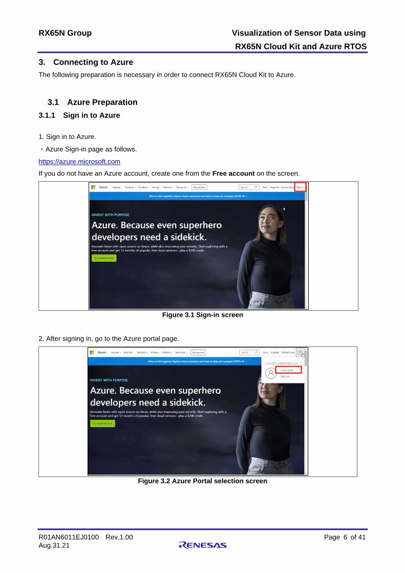
1. Sign in to Azure.
・Azure Sign-in page as follows.
https://azure.microsoft.com
If you do not have an Azure account, create one from the Free account on the screen.
Figure 3.1 Sign-in screen
2. After signing in, go to the Azure portal page.
Figure 3.2 Azure Portal selection screen

RX65N Group Visualization of Sensor Data using RX65N Cloud Kit and Azure RTOS
R01AN6011EJ0100 Rev.1.00 Page 7 of 41 Aug.31.21
3.1.2 Create an Azure IoT Hub
1. Click Create a resource.
Figure 3.3 Create a resource
2. Enter “IoT Hub” and click IoT Hub from the displayed candidates.
Figure 3.4 IoT Hub Search → IoT Hub Selection
3. Click Create.
Figure 3.5 IoT Hub Create

RX65N Group Visualization of Sensor Data using RX65N Cloud Kit and Azure RTOS
R01AN6011EJ0100 Rev.1.00 Page 8 of 41 Aug.31.21
4. On the Basics tab, select the Subscription that suitable your environment then enter the Resource group, Region and IoT hub name* → Click Next: Networking >. Note: The IoT hub name must be unique across the Azure cloud.
Figure 3.6 IoT Hub Basics Information Settings → Next: Networking >
5. On the Networking tab, select Public endpoint → Click Next: Management >.
Figure 3.7 Select Public endpoint → Next: Management >

RX65N Group Visualization of Sensor Data using RX65N Cloud Kit and Azure RTOS
R01AN6011EJ0100 Rev.1.00 Page 9 of 41 Aug.31.21
6. On the Management tab, select the Pricing and scale tier that suitable your environment → Click Next: Tags >.
If you select a Pricing and scale tier other than the F1: Free tier, set the subsequent setting items as necessary.
Figure 3.8 Select the Pricing and scale tier → Next: Tags >
7. On the Tags tab, set tags as needed → Click Next: Review + create >.
This document does not require any input, so do not enter anything and click Next: Review + create >.
Figure 3.9 Set tags → Next: Review + create >

RX65N Group Visualization of Sensor Data using RX65N Cloud Kit and Azure RTOS
R01AN6011EJ0100 Rev.1.00 Page 10 of 41 Aug.31.21
8. On the Review + create tab, review your selection → Click Create if you are satisfied. Creating an IoT Hub takes a few minutes.
Figure 3.10 Review your selection → Create
9. Once the IoT Hub is created, click Go to resource.
Figure 3.11 Go to resource

RX65N Group Visualization of Sensor Data using RX65N Cloud Kit and Azure RTOS
R01AN6011EJ0100 Rev.1.00 Page 11 of 41 Aug.31.21
10. Make a note of the Hostname with a text editor. The Hostname information will be used later.
Figure 3.12 IoT Hub Hostname recording
3.1.3 Create an IoT Device
1. Click IoT devices on the left side of the screen → Click Add Device.
Figure 3.13 IoT devices → Add Device

RX65N Group Visualization of Sensor Data using RX65N Cloud Kit and Azure RTOS
R01AN6011EJ0100 Rev.1.00 Page 12 of 41 Aug.31.21
2. In Create a Device, enter and select the following information → Click Save. ― Device ID → Enter arbitrary name
― Authentication type → Symmetric key
― Auto-generate keys → Put a check
― connect this device to an IoT hub → Enable
Figure 3.14 Device ID information settings → Save
3. Make a note of the Device ID name with a text editor and click the Device ID. The Device ID name information will be used later.
Figure 3.15 Click Device ID

RX65N Group Visualization of Sensor Data using RX65N Cloud Kit and Azure RTOS
R01AN6011EJ0100 Rev.1.00 Page 13 of 41 Aug.31.21
4. Make a note of the Primary Key with a text editor. The Primary Key information will be used later.
Figure 3.16 Device ID Primary Key recording

RX65N Group Visualization of Sensor Data using RX65N Cloud Kit and Azure RTOS
R01AN6011EJ0100 Rev.1.00 Page 14 of 41 Aug.31.21
3.2 Software Preparation Follow the steps below to prepare the software for the demo program. 1. Download the sample project. Download the Azure RTOS project for the RX65N Cloud Kit and GCC compiler combination from the Azure RTOS sample page on GitHub. ・GitHub sample page as follows.
https://github.com/azure-rtos/samples
Figure 3.17 GitHub sample page
2. Extract the project files from the archive and copy them to a suitable location. (In the description below, the root folder containing the project files is designated as ${base_folder}.) Note: After extracting the project files from the archive, copy them to a location with a short file path,
such as the root folder on the C: drive. If the file path is too long, a build error may result.

RX65N Group Visualization of Sensor Data using RX65N Cloud Kit and Azure RTOS
R01AN6011EJ0100 Rev.1.00 Page 15 of 41 Aug.31.21
3. Launch e2 studio and specify a workspace directory.
Figure 3.18 Workspace selection screen
4. Select File → Import….
Figure 3.19 Select File → Import…

RX65N Group Visualization of Sensor Data using RX65N Cloud Kit and Azure RTOS
R01AN6011EJ0100 Rev.1.00 Page 16 of 41 Aug.31.21
5. Click General → Existing Projects into Workspace → Next >.
Figure 3.20 General → Existing Projects into Workspace → Next >
6. Click Browse…, specify ${base_folder}/rx65n-cloud-kit folder → select all of the sample project extracted → Click Finish.
Figure 3.21 Project import screen

RX65N Group Visualization of Sensor Data using RX65N Cloud Kit and Azure RTOS
R01AN6011EJ0100 Rev.1.00 Page 17 of 41 Aug.31.21
7. Define the following two macros in {$base_folder}/rx65n-cloud-kit/e2studio_gnurx/sample_pnp_temperature_controller/src/main.c. ― WIFI_SSID → The SSID of the access point to connect to.
― WIFI_PASSWORD → The password of the access point to connect to.
(Makes sure to enclose the above macro definitions in quotes (" ") as shown in the figure below.
Figure 3.22 main.c
8. Define the following three macros in {$base_folder}/rx65n-cloud-kit/e2studio_gnurx/sample_pnp_temperature_controller/src/sample_config.h.
― HOST_NAME → The hostname confirmed as described in 3.1, Azure Preparation.
― DEVICE_ID → The Device ID created as described in 3.1, Azure Preparation.
― DEVICE_SYMMETRIC_KEY → The Primary Key confirmed as described in 3.1, Azure Preparation.
Figure 3.23 sample_config.h

RX65N Group Visualization of Sensor Data using RX65N Cloud Kit and Azure RTOS
R01AN6011EJ0100 Rev.1.00 Page 18 of 41 Aug.31.21
9. Save your changes and click Project → Clean….
Figure 3.24 Project → Clean…
10. Uncheck Clean all projects, check only sample_pnp_temperature_controller, click Clean, and confirm that 0 errors are reported.
Figure 3.25 Clean setting screen
Figure 3.26 Clean completion screen

RX65N Group Visualization of Sensor Data using RX65N Cloud Kit and Azure RTOS
R01AN6011EJ0100 Rev.1.00 Page 19 of 41 Aug.31.21
3.3 Running the Demo Program Preparation Prepare to run the demo program. 3.3.1 Hardware Preparation 1. Remove the jumper from the EJ2 pins on the target board (bottom board). 2. Connect the ECN1 connector on the target board (bottom board) to the PC via a USB cable. 3. Connect the CN18 connector on the cloud option board (top board) to the PC via a USB cable.
Figure 3.27 RX65N Cloud Kit (Top)
Figure 3.28 RX65N Cloud Kit (Bottom)
①
①
②
③
RX65N Group Visualization of Sensor Data using RX65N Cloud Kit and Azure RTOS
R01AN6011EJ0100 Rev.1.00 Page 20 of 41 Aug.31.21
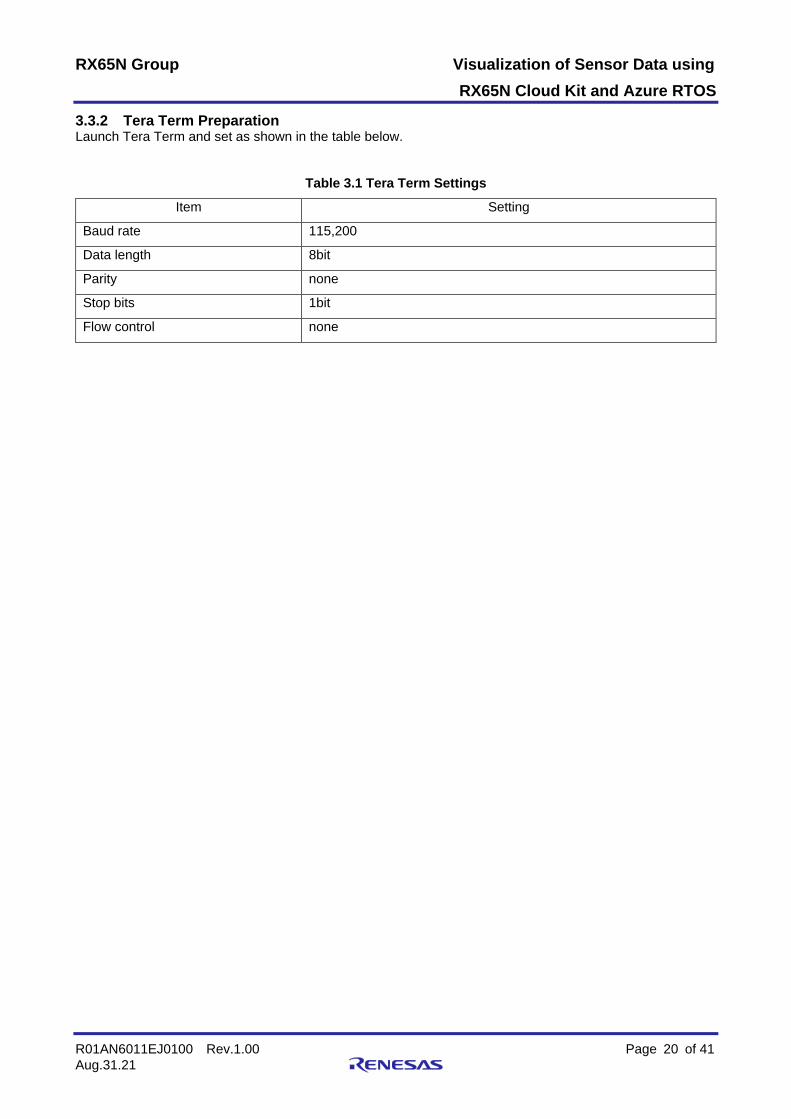
3.3.2 Tera Term Preparation Launch Tera Term and set as shown in the table below.
Table 3.1 Tera Term Settings
Item Setting
Baud rate 115,200
Data length 8bit
Parity none
Stop bits 1bit
Flow control none

RX65N Group Visualization of Sensor Data using RX65N Cloud Kit and Azure RTOS
R01AN6011EJ0100 Rev.1.00 Page 21 of 41 Aug.31.21
3.4 Running the Demo Program Follow the steps below to run the demo program. 1. Click sample_pnp_temperature_controller HardwareDebug from the drop-down list in the upper left of the e2 studio window.
Figure 3.29 Hardware Debug selection
2. Click the Debug icon.
Figure 3.30 Debug
3. A message appears asking you to confirm that you wish to switch to the Debug perspective; click the Switch button. 4. Click the Restart icon. After a short time execution pauses at the main function; click the Resume icon.
Figure 3.31 Demo program execution
5. Confirm that the execution log is output on the Tera Term screen.
Figure 3.32 Demo program execution log

RX65N Group Visualization of Sensor Data using RX65N Cloud Kit and Azure RTOS
R01AN6011EJ0100 Rev.1.00 Page 22 of 41 Aug.31.21
3.5 Communication confirmation by Azure IoT Explorer Confirm the uploaded data is sent to the Azure cloud. 1. Access the created IoT Hub page on the Azure portal and the Shared access policies → iothubowner → Get Primary connection string.
Figure 3.33 shared access policies → iothubowner → Primary connection string
2. Launch Azure IoT Explorer and click Add connection.
Figure 3.34 Azure IoT Explorer

RX65N Group Visualization of Sensor Data using RX65N Cloud Kit and Azure RTOS
R01AN6011EJ0100 Rev.1.00 Page 23 of 41 Aug.31.21
3. Enter the got Primary connection string in Connection string → Click Save.
Figure 3.35 Enter the primary connection string in Azure IoT Explorer → Save
4. Create a folder named models in your local folder. 5. Go to the IoT Plug and Play quickstarts web page and download the two model files into the models folder. ・IoT Plug and Play quickstarts web page as follows.
https://docs.microsoft.com/azure/iot-develop/set-up-environment
Figure 3.36 Download model file

RX65N Group Visualization of Sensor Data using RX65N Cloud Kit and Azure RTOS
R01AN6011EJ0100 Rev.1.00 Page 24 of 41 Aug.31.21
6. Click IoT Plug and Play components in Azure IoT Explorer → Add → Click Local folder in the pull-down.
Figure 3.37 IoT Plug and Play components → Add → Local folder
7. Pick a folder → Select the models folder where you saved the model file → Click Save.
Figure 3.38 Pick a folder → Select the models folder where you saved the model file → Save
8. Click IoT hubs on the left side of the screen → Created IoT Hub.
Figure 3.39 IoT Hub selection

RX65N Group Visualization of Sensor Data using RX65N Cloud Kit and Azure RTOS
R01AN6011EJ0100 Rev.1.00 Page 25 of 41 Aug.31.21
9. Click the Device ID name.
Figure 3.40 Device ID selection
10. Click the IoT Plug and Play components.
Figure 3.41 Device ID selection

RX65N Group Visualization of Sensor Data using RX65N Cloud Kit and Azure RTOS
R01AN6011EJ0100 Rev.1.00 Page 26 of 41 Aug.31.21
11. Scroll down the page and click thermostat1 from Components.
Figure 3.42 thermostat1 selection
12. Click the Telemetry.
Figure 3.43 Telemetry selection
13. Click the Start.
Figure 3.44 Telemetry started

RX65N Group Visualization of Sensor Data using RX65N Cloud Kit and Azure RTOS
R01AN6011EJ0100 Rev.1.00 Page 27 of 41 Aug.31.21
14. Confirm that the uploaded data is displayed in the Receiving events field → Click Stop.
Figure 3.45 Telemetry data confirmation
15. Click the Stop icon on the e2 studio screen.
Figure 3.46 Demo program stop

RX65N Group Visualization of Sensor Data using RX65N Cloud Kit and Azure RTOS
R01AN6011EJ0100 Rev.1.00 Page 28 of 41 Aug.31.21
4. LED ON/OFF operation by Azure IoT Explorer Follow the steps below to turning on/off LED1 on the RX65N Cloud Kit from the Azure cloud.
To operate LED1, you need to make changes to the sample project downloaded from the Azure RTOS sample page on GitHub in 3.2 Software Preparation.Please refer to 8. Appendices for the changes.
1. Click the device ID created in Azure IoT Explorer → Click Device twin.
Figure 4.1 Device twin screen
2. Add the following lines of code into desired properties → Click Save.
“LED”: {
“LED1”: 1
},
Figure 4.2 Message payload to turn on LED1

RX65N Group Visualization of Sensor Data using RX65N Cloud Kit and Azure RTOS
R01AN6011EJ0100 Rev.1.00 Page 29 of 41 Aug.31.21
Figure 4.3 Device twin setting state
3. Confirm that RX65N Cloud Kit LED1 turn on.
Figure 4.4 LED1 turn on

RX65N Group Visualization of Sensor Data using RX65N Cloud Kit and Azure RTOS
R01AN6011EJ0100 Rev.1.00 Page 30 of 41 Aug.31.21
4. Add the following lines of code into desired properties → Click Save. “LED”: {
“LED1”: 0
},
Figure 4.5 Message payload to turn off LED1 5. Confirm that RX65N Cloud Kit LED1 turn off.
Figure 4.6 LED1 turn off

RX65N Group Visualization of Sensor Data using RX65N Cloud Kit and Azure RTOS
R01AN6011EJ0100 Rev.1.00 Page 31 of 41 Aug.31.21
5. Visualization of Sensor Data Follow the steps below to visualizing the sensor data* uploaded from the RX65N Cloud Kit to the Azure cloud using a web application.
Note: The demo program in this document uploads fixed values as sensor data.
5.1 Software Preparation 1. Go to the IoT Hub page you created on the Azure portal Built-in endpoints → Enter arbitrary name to Create new consumer group → Click Save.
Figure 5.1 Consumer group creation
2. Make a note of the consumer group name with a text editor.
The consumer group name information will be used later.
3. Make a note of the Shared access policies → service → Primary connection string with a text editor.
The Primary connection string information will be used later.
Figure 5.2 Shared access policies → service → Primary connection string

RX65N Group Visualization of Sensor Data using RX65N Cloud Kit and Azure RTOS
R01AN6011EJ0100 Rev.1.00 Page 32 of 41 Aug.31.21
5.2 Running the web application 1. Start the command prompt and run the commands in the following order.
(1) Download the sample code of the web application for visualization from GitHub.
git clone https://github.com/Azure-Samples/web-apps-node-iot-hub-data-visualization.git
Figure 5.3 Web application sample code download
(2) Move the folder to the storage location of the sample code.
cd web-apps-node-iot-hub-data-visualization
Figure 5.4 Move sample code folder
(3) Set environment variables.
set IotHubConnectionString=[5.1 Software Preparation 3. Primary connection string]
set EventHubConsumerGroup=[5.1 Software Preparation 2. consumer group name]
Figure 5.5 Environment variable settings
(4) Launch website.
Enter Ctrl-C to exit the website.
npm install
npm start
Figure 5.6 Launch website
Figure 5.7 Command prompt screen
2. Run the demo program according to the procedure in 3.4 Running the demo program.

RX65N Group Visualization of Sensor Data using RX65N Cloud Kit and Azure RTOS
R01AN6011EJ0100 Rev.1.00 Page 33 of 41 Aug.31.21
3. Start your browser and go to http://localhost:3000 to see the temperature data graph.
Figure 5.8 Web application screen

RX65N Group Visualization of Sensor Data using RX65N Cloud Kit and Azure RTOS
R01AN6011EJ0100 Rev.1.00 Page 34 of 41 Aug.31.21
5.3 Display of graph changes The sample program allows you to change the value of the sensor data to be uploaded. The changed data can be confirmed in the graph.
1. Go to the Device ID you created on the Azure portal → IoT Plug and Play components → Scroll down and click thermostat1 from Component.
Figure 5.9 Components screen
2. Click Properties (writable).
Figure 5.10 Properties (writable) selection

RX65N Group Visualization of Sensor Data using RX65N Cloud Kit and Azure RTOS
R01AN6011EJ0100 Rev.1.00 Page 35 of 41 Aug.31.21
3. Enter the temperature data in target Temperature → Click Update desired value.
Figure 5.11 Enter the temperature data → Update desired value
4. Go to http://localhost:3000 and check that the graph is changing.
Figure 5.12 Check the sensor data change on the web application screen
5. Click the Stop icon on the e2 studio screen to end the demo run.

RX65N Group Visualization of Sensor Data using RX65N Cloud Kit and Azure RTOS
R01AN6011EJ0100 Rev.1.00 Page 36 of 41 Aug.31.21
6. Important Note after Running Demo Program Fees are incurred when are using the Azure Service. Make sure to delete your account if you will no longer be using it.
7. Websites and Support Azure RTOS: https://azure.microsoft.com/support/community/
Azure RTOS GitHub: https://github.com/azure-rtos
8. Appendices The changes required for the sample program to perform 4. LED ON/OFF operation by Azure IoT Explorer are shown below.
Note: The line numbers in the description indicate the number of lines in the sample program at the time of download.
1. Make the following changes to “{$base_folder}/rx65n-cloud-kit/e2studio_gnurx/sample_pnp_temperature_controller/src/sample_pnp_temperature_controller.c”.
(1) Add the following variable declarations. l.143 static const CHAR sample_device_info_component[] = "deviceInformation";
static SAMPLE_PNP_THERMOSTAT_COMPONENT sample_led;
static const CHAR sample_led_component[] = "LED";
static double sample_led_last_device_reported;
Figure 8.1 Changed sample_pnp_temperature_controller.c (1)
(2) Add elements for LEDs to the sample_components array. l.146
l.147
l.148
static const CHAR *sample_components[] = { sample_thermostat_1_component,
sample_thermostat_2_component,
sample_led_component,
sample_device_info_component };
Figure 8.2 Changed sample_pnp_temperature_controller.c (2)
Add
Add

RX65N Group Visualization of Sensor Data using RX65N Cloud Kit and Azure RTOS
R01AN6011EJ0100 Rev.1.00 Page 37 of 41 Aug.31.21
(3) Add a conditional expression to the following if statement of the sample_desired_property_callback() function.
l.811 l.812 l.834 l.835 l.836
if (component_name_ptr == NULL || component_name_len == 0) { (略)
} else if (sample_pnp_led_process_property_update(&sample_led, (NX_AZURE_IOT_HUB_CLIENT *)userContextCallback, component_name_ptr, component_name_len, property_name_ptr, property_name_len, &property_value_reader, version) == NX_AZURE_IOT_SUCCESS) { printf("property updated of led1¥r¥n"); } else { …
}
Figure 8.3 Changed sample_pnp_temperature_controller.c (3) (4) Add conditional expression to the following if statement of sample_components_init() function.
l.1232 l.1233 l.1234 l.1235 l.1236 l.1247 l.1248 l.1249
if ((status = sample_pnp_thermostat_init(&sample_thermostat_1, (UCHAR *)sample_thermostat_1_component, sizeof(sample_thermostat_1_component) - 1, SAMPLE_DEFAULT_START_TEMP_CELSIUS))) { … } else if ((status = sample_pnp_thermostat_init(&sample_led,
(UCHAR *)sample_led_component, sizeof(sample_led_component) - 1,
SAMPLE_DEFAULT_START_TEMP_CELSIUS))) { printf("Failed to initialize %s: error code = 0x%08x¥r¥n", sample_led_component, status); } sample_thermostat_1_last_device_max_temp_reported = 0;
Figure 8.4 Changed sample_pnp_temperature_controller.c (4)
Add
Add

RX65N Group Visualization of Sensor Data using RX65N Cloud Kit and Azure RTOS
R01AN6011EJ0100 Rev.1.00 Page 38 of 41 Aug.31.21
2. Make the following changes to “{$base_folder}/rx65n-cloud-kit/e2studio_gnurx/sample_pnp_temperature_controller/src/sample_pnp_thermostat_component.c”.
(1) Add include settings in platform.h file. l.12 #include "sample_pnp_thermostat_component.h"
#include "platform.h"
Figure 8.5 Changed sample_pnp_thermostat_component.c (1) (2) Add a constant for the data key name LED1 that communicates with Azure.
l.36 static const CHAR temp_response_description_failed[] = "failed";
static const CHAR led_property_name[] = "LED1";
Figure 8.6 Changed sample_pnp_thermostat_component.c (2) (3) Add 2 functions used for Device twin operation.
Last line
static VOID sample_send_led_report(SAMPLE_PNP_THERMOSTAT_COMPONENT *handle, NX_AZURE_IOT_HUB_CLIENT *iothub_client_ptr, double temp, INT status_code, UINT version, const CHAR *description) {
UINT bytes_copied; UINT response_status; UINT request_id; NX_AZURE_IOT_JSON_WRITER json_writer; ULONG reported_property_version;
/* Build telemetry JSON payload */ if (nx_azure_iot_json_writer_with_buffer_init(&json_writer, scratch_buffer, sizeof(scratch_buffer))) { printf("Failed to create json writer¥r¥n"); return; } if (nx_azure_iot_pnp_helper_build_reported_property_with_status(
handle -> component_name_ptr, handle -> component_name_length, (UCHAR *)led_property_name, sizeof(led_property_name) - 1, append_temp, (VOID *)&temp, status_code, (UCHAR *)description, strlen(description), version, &json_writer)) { printf("Failed to create reported response¥r¥n"); } else { bytes_copied = nx_azure_iot_json_writer_get_bytes_used(&json_writer); if (nx_azure_iot_hub_client_device_twin_reported_properties_send(iothub_client_ptr, scratch_buffer, bytes_copied, &request_id, &response_status, &reported_property_version, (5 * NX_IP_PERIODIC_RATE))) { printf("Failed to send reported response¥r¥n"); } } nx_azure_iot_json_writer_deinit(&json_writer); }
Figure 8.7 Changed sample_pnp_thermostat_component.c (3)-1
Add
Add

RX65N Group Visualization of Sensor Data using RX65N Cloud Kit and Azure RTOS
R01AN6011EJ0100 Rev.1.00 Page 39 of 41 Aug.31.21
Last line
UINT sample_pnp_led_process_property_update(SAMPLE_PNP_THERMOSTAT_COMPONENT *handle, NX_AZURE_IOT_HUB_CLIENT *iothub_client_ptr, CHAR *component_name_ptr, UINT component_name_length, UCHAR *property_name_ptr, UINT property_name_length, NX_AZURE_IOT_JSON_READER *property_value_reader_ptr, UINT version) {
double parsed_value = 0; INT status_code; const CHAR *description;
if (handle == NX_NULL) { return(NX_NOT_SUCCESSFUL); } if (handle -> component_name_length != component_name_length || strncmp((CHAR *)handle -> component_name_ptr,
(CHAR *)component_name_ptr, component_name_length) != 0) { return(NX_NOT_SUCCESSFUL); } if (property_name_length != (sizeof(led_property_name) - 1) || strncmp((CHAR *)property_name_ptr, (CHAR *)led_property_name, property_name_length) != 0) { printf("PnP property=%.*s is not supported on thermostat component¥r¥n", property_name_length, property_name_ptr); status_code = 404; description = temp_response_description_failed; } else if (nx_azure_iot_json_reader_token_double_get(property_value_reader_ptr, &parsed_value)) { status_code = 401; description = temp_response_description_failed; } else { status_code = 200; description = temp_response_description_success; if (parsed_value == 1) // LED ON { PORTB.PDR.BIT.B0 = 1; PORTB.PODR.BIT.B0 = 0; } else // LED OFF { PORTB.PDR.BIT.B0 = 1; PORTB.PODR.BIT.B0 = 1; } } sample_send_led_report(handle, iothub_client_ptr, parsed_value, status_code, version, description); return(NX_AZURE_IOT_SUCCESS); }
Figure 8.8 Changed sample_pnp_thermostat_component.c (3)-2

RX65N Group Visualization of Sensor Data using RX65N Cloud Kit and Azure RTOS
R01AN6011EJ0100 Rev.1.00 Page 40 of 41 Aug.31.21
3. Make the following changes to “{$base_folder}/rx65n-cloud-kit/e2studio_gnurx/sample_pnp_temperature_controller/src/sample_pnp_thermostat_component.h”.
(1) Add the declaration of the sample_pnp_led_process_property_update() function. l.65
l.66
l.67
l.68
l.69
UINT sample_pnp_thermostat_process_property_update(SAMPLE_PNP_THERMOSTAT_COMPONENT *handle,
NX_AZURE_IOT_HUB_CLIENT *iothub_client_ptr,
UCHAR *component_name_ptr, UINT component_name_length,
UCHAR *property_name_ptr, UINT property_name_length,
NX_AZURE_IOT_JSON_READER *property_value_reader_ptr, UINT version);
UINT sample_pnp_led_process_property_update(SAMPLE_PNP_THERMOSTAT_COMPONENT *handle,
NX_AZURE_IOT_HUB_CLIENT *iothub_client_ptr,
UCHAR *component_name_ptr, UINT component_name_length,
UCHAR *property_name_ptr, UINT property_name_length,
NX_AZURE_IOT_JSON_READER *property_value_reader_ptr, UINT version);
Figure 8.9 Changed sample_pnp_thermostat_component.h (1)
Add

RX65N Group Visualization of Sensor Data using RX65N Cloud Kit and Azure RTOS
R01AN6011EJ0100 Rev.1.00 Page 41 of 41 Aug.31.21
Revision History
Rev. Date Description Page Summary
1.00 XX.XX.21 ‐ First edition

General Precautions in the Handling of Microprocessing Unit and Microcontroller Unit Products The following usage notes are applicable to all Microprocessing unit and Microcontroller unit products from Renesas. For detailed usage notes on the products covered by this document, refer to the relevant sections of the document as well as any technical updates that have been issued for the products.
1. Precaution against Electrostatic Discharge (ESD)
A strong electrical field, when exposed to a CMOS device, can cause destruction of the gate oxide and ultimately degrade the device operation. Steps
must be taken to stop the generation of static electricity as much as possible, and quickly dissipate it when it occurs. Environmental control must be
adequate. When it is dry, a humidifier should be used. This is recommended to avoid using insulators that can easily build up static electricity.
Semiconductor devices must be stored and transported in an anti-static container, static shielding bag or conductive material. All test and
measurement tools including work benches and floors must be grounded. The operator must also be grounded using a wrist strap. Semiconductor
devices must not be touched with bare hands. Similar precautions must be taken for printed circuit boards with mounted semiconductor devices. 2. Processing at power-on
The state of the product is undefined at the time when power is supplied. The states of internal circuits in the LSI are indeterminate and the states of
register settings and pins are undefined at the time when power is supplied. In a finished product where the reset signal is applied to the external reset
pin, the states of pins are not guaranteed from the time when power is supplied until the reset process is completed. In a similar way, the states of pins
in a product that is reset by an on-chip power-on reset function are not guaranteed from the time when power is supplied until the power reaches the
level at which resetting is specified. 3. Input of signal during power-off state
Do not input signals or an I/O pull-up power supply while the device is powered off. The current injection that results from input of such a signal or I/O
pull-up power supply may cause malfunction and the abnormal current that passes in the device at this time may cause degradation of internal
elements. Follow the guideline for input signal during power-off state as described in your product documentation. 4. Handling of unused pins
Handle unused pins in accordance with the directions given under handling of unused pins in the manual. The input pins of CMOS products are
generally in the high-impedance state. In operation with an unused pin in the open-circuit state, extra electromagnetic noise is induced in the vicinity of
the LSI, an associated shoot-through current flows internally, and malfunctions occur due to the false recognition of the pin state as an input signal
become possible. 5. Clock signals
After applying a reset, only release the reset line after the operating clock signal becomes stable. When switching the clock signal during program
execution, wait until the target clock signal is stabilized. When the clock signal is generated with an external resonator or from an external oscillator
during a reset, ensure that the reset line is only released after full stabilization of the clock signal. Additionally, when switching to a clock signal
produced with an external resonator or by an external oscillator while program execution is in progress, wait until the target clock signal is stable. 6. Voltage application waveform at input pin
Waveform distortion due to input noise or a reflected wave may cause malfunction. If the input of the CMOS device stays in the area between VIL
(Max.) and VIH (Min.) due to noise, for example, the device may malfunction. Take care to prevent chattering noise from entering the device when the
input level is fixed, and also in the transition period when the input level passes through the area between VIL (Max.) and VIH (Min.). 7. Prohibition of access to reserved addresses
Access to reserved addresses is prohibited. The reserved addresses are provided for possible future expansion of functions. Do not access these
addresses as the correct operation of the LSI is not guaranteed. 8. Differences between products
Before changing from one product to another, for example to a product with a different part number, confirm that the change will not lead to problems.
The characteristics of a microprocessing unit or microcontroller unit products in the same group but having a different part number might differ in terms
of internal memory capacity, layout pattern, and other factors, which can affect the ranges of electrical characteristics, such as characteristic values,
operating margins, immunity to noise, and amount of radiated noise. When changing to a product with a different part number, implement a system-
evaluation test for the given product.

© 2021 Renesas Electronics Corporation. All rights reserved.
Notice 1. Descriptions of circuits, software and other related information in this document are provided only to illustrate the operation of semiconductor products
and application examples. You are fully responsible for the incorporation or any other use of the circuits, software, and information in the design of your product or system. Renesas Electronics disclaims any and all liability for any losses and damages incurred by you or third parties arising from the use of these circuits, software, or information.
2. Renesas Electronics hereby expressly disclaims any warranties against and liability for infringement or any other claims involving patents, copyrights, or other intellectual property rights of third parties, by or arising from the use of Renesas Electronics products or technical information described in this document, including but not limited to, the product data, drawings, charts, programs, algorithms, and application examples.
3. No license, express, implied or otherwise, is granted hereby under any patents, copyrights or other intellectual property rights of Renesas Electronics or others.
4. You shall be responsible for determining what licenses are required from any third parties, and obtaining such licenses for the lawful import, export, manufacture, sales, utilization, distribution or other disposal of any products incorporating Renesas Electronics products, if required.
5. You shall not alter, modify, copy, or reverse engineer any Renesas Electronics product, whether in whole or in part. Renesas Electronics disclaims any and all liability for any losses or damages incurred by you or third parties arising from such alteration, modification, copying or reverse engineering.
6. Renesas Electronics products are classified according to the following two quality grades: “Standard” and “High Quality”. The intended applications for each Renesas Electronics product depends on the product’s quality grade, as indicated below. "Standard": Computers; office equipment; communications equipment; test and measurement equipment; audio and visual equipment; home
electronic appliances; machine tools; personal electronic equipment; industrial robots; etc. "High Quality": Transportation equipment (automobiles, trains, ships, etc.); traffic control (traffic lights); large-scale communication equipment; key
financial terminal systems; safety control equipment; etc. Unless expressly designated as a high reliability product or a product for harsh environments in a Renesas Electronics data sheet or other Renesas Electronics document, Renesas Electronics products are not intended or authorized for use in products or systems that may pose a direct threat to human life or bodily injury (artificial life support devices or systems; surgical implantations; etc.), or may cause serious property damage (space system; undersea repeaters; nuclear power control systems; aircraft control systems; key plant systems; military equipment; etc.). Renesas Electronics disclaims any and all liability for any damages or losses incurred by you or any third parties arising from the use of any Renesas Electronics product that is inconsistent with any Renesas Electronics data sheet, user’s manual or other Renesas Electronics document.
7. No semiconductor product is absolutely secure. Notwithstanding any security measures or features that may be implemented in Renesas Electronics hardware or software products, Renesas Electronics shall have absolutely no liability arising out of any vulnerability or security breach, including but not limited to any unauthorized access to or use of a Renesas Electronics product or a system that uses a Renesas Electronics product. RENESAS ELECTRONICS DOES NOT WARRANT OR GUARANTEE THAT RENESAS ELECTRONICS PRODUCTS, OR ANY SYSTEMS CREATED USING RENESAS ELECTRONICS PRODUCTS WILL BE INVULNERABLE OR FREE FROM CORRUPTION, ATTACK, VIRUSES, INTERFERENCE, HACKING, DATA LOSS OR THEFT, OR OTHER SECURITY INTRUSION (“Vulnerability Issues”). RENESAS ELECTRONICS DISCLAIMS ANY AND ALL RESPONSIBILITY OR LIABILITY ARISING FROM OR RELATED TO ANY VULNERABILITY ISSUES. FURTHERMORE, TO THE EXTENT PERMITTED BY APPLICABLE LAW, RENESAS ELECTRONICS DISCLAIMS ANY AND ALL WARRANTIES, EXPRESS OR IMPLIED, WITH RESPECT TO THIS DOCUMENT AND ANY RELATED OR ACCOMPANYING SOFTWARE OR HARDWARE, INCLUDING BUT NOT LIMITED TO THE IMPLIED WARRANTIES OF MERCHANTABILITY, OR FITNESS FOR A PARTICULAR PURPOSE.
8. When using Renesas Electronics products, refer to the latest product information (data sheets, user’s manuals, application notes, “General Notes for Handling and Using Semiconductor Devices” in the reliability handbook, etc.), and ensure that usage conditions are within the ranges specified by Renesas Electronics with respect to maximum ratings, operating power supply voltage range, heat dissipation characteristics, installation, etc. Renesas Electronics disclaims any and all liability for any malfunctions, failure or accident arising out of the use of Renesas Electronics products outside of such specified ranges.
9. Although Renesas Electronics endeavors to improve the quality and reliability of Renesas Electronics products, semiconductor products have specific characteristics, such as the occurrence of failure at a certain rate and malfunctions under certain use conditions. Unless designated as a high reliability product or a product for harsh environments in a Renesas Electronics data sheet or other Renesas Electronics document, Renesas Electronics products are not subject to radiation resistance design. You are responsible for implementing safety measures to guard against the possibility of bodily injury, injury or damage caused by fire, and/or danger to the public in the event of a failure or malfunction of Renesas Electronics products, such as safety design for hardware and software, including but not limited to redundancy, fire control and malfunction prevention, appropriate treatment for aging degradation or any other appropriate measures. Because the evaluation of microcomputer software alone is very difficult and impractical, you are responsible for evaluating the safety of the final products or systems manufactured by you.
10. Please contact a Renesas Electronics sales office for details as to environmental matters such as the environmental compatibility of each Renesas Electronics product. You are responsible for carefully and sufficiently investigating applicable laws and regulations that regulate the inclusion or use of controlled substances, including without limitation, the EU RoHS Directive, and using Renesas Electronics products in compliance with all these applicable laws and regulations. Renesas Electronics disclaims any and all liability for damages or losses occurring as a result of your noncompliance with applicable laws and regulations.
11. Renesas Electronics products and technologies shall not be used for or incorporated into any products or systems whose manufacture, use, or sale is prohibited under any applicable domestic or foreign laws or regulations. You shall comply with any applicable export control laws and regulations promulgated and administered by the governments of any countries asserting jurisdiction over the parties or transactions.
12. It is the responsibility of the buyer or distributor of Renesas Electronics products, or any other party who distributes, disposes of, or otherwise sells or transfers the product to a third party, to notify such third party in advance of the contents and conditions set forth in this document.
13. This document shall not be reprinted, reproduced or duplicated in any form, in whole or in part, without prior written consent of Renesas Electronics. 14. Please contact a Renesas Electronics sales office if you have any questions regarding the information contained in this document or Renesas
Electronics products.
(Note1) “Renesas Electronics” as used in this document means Renesas Electronics Corporation and also includes its directly or indirectly controlled subsidiaries.
(Note2) “Renesas Electronics product(s)” means any product developed or manufactured by or for Renesas Electronics. (Rev.5.0-1 October 2020)
Corporate Headquarters Contact information TOYOSU FORESIA, 3-2-24 Toyosu, Koto-ku, Tokyo 135-0061, Japan www.renesas.com
For further information on a product, technology, the most up-to-date version of a document, or your nearest sales office, please visit: www.renesas.com/contact/.
Trademarks Renesas and the Renesas logo are trademarks of Renesas Electronics Corporation. All trademarks and registered trademarks are the property of their respective owners.