rx and rx changed to rxb family cs7b - cs7...
TRANSCRIPT
OPERATOR MANUAL
C Copyright 1999 by STÄUBLI FAVERGESD.280.096.04.B - 06/00
"RX" and "RX changed to RXB" familyCS7B - CS7 MB
1st edition 99.07

OPERATOR MANUAL
CARTESIAN COORDINATES
POLAR COORDINATES
DIFFERENT CATEGORIES OF ROBOTSGEOMETRICAL CONFIGURATIONS
36
108
48

OPERATOR MANUAL
PRESENTATION and FUNCTIONALITIES OFTHE STAUBLI ROBOT SYSTEM
CS7B / CS7 MB GENERAL STRUCTURE
Main switch
Alphanumericalor graphic terminal Teach pendant
Axis 6
Axis 5
Axis 4
Axis 3
Axis 2
Axis 1RX ARM
Amplifiers
INTERFACE AWCBoard
Controller(V+ langage)

OPERATOR MANUAL
V+ LANGUAGE
The V+ language is adapted to the robotics and allows the robot arm or outputs to execute specific tasks.
The V+ language has its owner syntaxis which commands its structure.
Some definitions :
A PROGRAM is a sequence of instructions which will be executed the ones after the others.
The VARIABLES are the datas on which these instructions work; there ara 3 types:
• the LOCATIONS positions stored in arm work envelope used to define the motion of the arm;
• the REALS digital values used for calculations;
• the STRINGS OF CHARACTERS messages in text form which are displayed on terminal screen.

D28009604 - 0600 I
OPERATOR MANUAL
CONTENTS
CHAPTER 1 - SAFETY ........................................................................................... 1.1
CHAPTER 2 - ROBOT START-UP ........................................................................ 2.1
2.1. INTRODUCTION........................................................................................................... 2.32.2. CONTROL POWER-UP ................................................................................................ 2.3
2.3. ARM POWER-UP ......................................................................................................... 2.32.3.1. AUTOMATIC MODE...................................................................................................... 2.32.3.2. MANUAL MODE ........................................................................................................... 2.42.4. CUTTING OFF POWER ON ARM ................................................................................ 2.4
CHAPTER 3 - TEACH PENDANT USE ................................................................. 3.1
3.1. GENERAL..................................................................................................................... 3.23.2. PRESENTATION OF TEACH PENDANT KEYS ............................................................ 3.33.2.1. USER KEYS................................................................................................................. 3.43.2.2. FUNCTION KEYS ......................................................................................................... 3.53.2.3. DATA ENTRY KEYS .................................................................................................... 3.83.2.4. MODE SELECTION KEYS ........................................................................................... 3.93.2.5. MANUAL CONTROL KEYS .......................................................................................... 3.123.3. ROBOT MANUAL MOTION MODES ............................................................................ 3.133.3.1. JOINT MODE ................................................................................................................ 3.133.3.2. FREE MODE ................................................................................................................ 3.133.3.3. BREAK RELEASE MODE ............................................................................................ 3.143.3.4. COORDINATES SYSTEM MODES............................................................................... 3.153.3.4.1. PRELIMINARY .............................................................................................................................. 3.153.3.4.2. COORDINATE SYSTEM IN RX ROBOTS..................................................................................... 3.173.3.5. HOW TO VISUALIZE THE CURRENT POSITION OF THE ARM ................................... 3.18
WHERE ........................................................................................................................................ 3.19
PAGE
D28009604 - 0600 II
OPERATOR MANUAL
PAGE
CHAPTER 4 - EXECUTION AND CONTROL OF A PROGRAM ........................... 4.1
4.1. HOW TO TRIGGER EXECUTION OF A PROGRAM..................................................... 4.2
4.2. HOW TO ADJUST ROBOT SPEED.............................................................................. 4.5
4.3. HOW TO EXECUTE A PROGRAM STEP BY STEP ..................................................... 4.64.4. HOW TO FOLLOW THE EXECUTION OF A PROGRAM ............................................. 4.7
4.5. HOW TO EXECUTE A SINGLE INSTRUCTION ........................................................... 4.8
4.6. HOW TO STOP A PROGRAM DURING EXECUTION.................................................. 4.94.7. HOW TO RESTART A PROGRAM............................................................................... 4.104.7.1. STOP BY ABORT......................................................................................................... 4.104.7.2. STOP BY RUN/HOLD OR MAN/HALT ON TEACH PENDANT ...................................... 4.10
4.8. MULTITASKS PROGRAMS ......................................................................................... 4.11STATUS........................................................................................................................................ 4.12KILL .............................................................................................................................................. 4.13
CHAPTER 5 - EDITOR ........................................................................................... 5.1
5.1. PRELIMINARY ............................................................................................................. 5.25.2. HOW TO EDIT A PROGRAM ....................................................................................... 5.35.2.1 LINE EDITOR: EDIT ...................................................................................................... 5.35.2.2. FULL-PAGE EDITOR: SEE ........................................................................................... 5.4
5.3. EDITING FUNCTION KEYS OF THE SEE EDITOR....................................................... 5.75.3.1. CURSOR CONTROL ..................................................................................................... 5.75.3.2. EDIT MULTIPLE PROGRAMS ...................................................................................... 5.85.3.3. SEARCH, FIND AND REPLACE ................................................................................... 5.95.3.4. TO QUIT EDITOR .......................................................................................................... 5.95.3.5. EDITOR ENVIRONMENT PROBLEMS ......................................................................... 5.9

D28009604 - 0600 III
OPERATOR MANUAL
CHAPTER 6 - DECLARATION OF VARIABLES ANDOPERATIONS ON MEMORY.......................................................... 6.1
6.1. REAL VARIABLES ....................................................................................................... 6.36.2. STRING VARIABLES ................................................................................................... 6.46.3. LOCATION VARIABLES .............................................................................................. 6.56.3.1. CARTESIAN LOCATIONS / PRECISION LOCATIONS .................................................. 6.56.3.2. DEFINE A LOCATION IN MONITOR COMMAND MODE............................................... 6.56.3.3. HOW TO MOVE THE TOOL REFERENCE SYSTEM ................................................... 6.6
TOOL ............................................................................................................................................ 6.76.3.4. HOW TO DEFINE A LOCATION BY TEACHING ........................................................... 6.86.4. INDEXED VARIABLES:ARRAYS .................................................................................. 6.9
TEACH ......................................................................................................................................... 6.11
6.5. MEMORY OPERATIONS.............................................................................................. 6.12DIR ............................................................................................................................................... 6.13LIST .............................................................................................................................................. 6.14COPY............................................................................................................................................ 6.16RENAME ...................................................................................................................................... 6.17DELETE ....................................................................................................................................... 6.18ZERO............................................................................................................................................ 6.19
CHAPTER 7 - SOME MOTION PROGRAM INSTRUCTIONS ............................... 7.1
MOVE............................................................................................................................................ 7.2MOVES ......................................................................................................................................... 7.4APPRO ......................................................................................................................................... 7.6APPROS....................................................................................................................................... 7.7DEPART ....................................................................................................................................... 7.8DEPARTS..................................................................................................................................... 7.9OPENI, CLOSEI ........................................................................................................................... 7.10OPEN, CLOSE ............................................................................................................................. 7.11DELAY .......................................................................................................................................... 7.12BREAK ......................................................................................................................................... 7.13TYPE ............................................................................................................................................ 7.14PROMPT ...................................................................................................................................... 7.16
CHAPTER 8 - DIGITAL INPUTS AND OUTPUTS ................................................. 8.1
8.1 EXTERNAL OUTPUTS (on/off) .................................................................................... 8.2SIGNAL......................................................................................................................................... 8.3RESET ......................................................................................................................................... 8.4
8.2 EXTERNAL INPUTS ..................................................................................................... 8.5IO .................................................................................................................................................. 8.6WAIT ............................................................................................................................................. 8.7
PAGE

D28009604 - 0600 IV
OPERATOR MANUAL
PAGE
CHAPTER 9 - DISKETTE OR DISC SAVING OPERATIONS ............................... 9.1
9.1. WHY YOU SHOULD USE A DIRECTORY..................................................................... 9.2
9.2 WHY YOU SHOULD SAVE PROGRAMS ..................................................................... 9.2
9.3 COMMANDS ASSOCIATED WITH COMPACT FLASH OR FLOPPY DISK DRIVE .... 9.3FDIRECTORY .............................................................................................................................. 9.4DEF D=... or CD ........................................................................................................................... 9.5STORE, STOREP, STOREL, STORER, STORES ....................................................................... 9.6LOAD ............................................................................................................................................ 9.7FDIRECTORY/C........................................................................................................................... 9.8FDIRECTORY/D........................................................................................................................... 9.9FLIST ............................................................................................................................................ 9.10FCOPY ......................................................................................................................................... 9.11FDELETE ..................................................................................................................................... 9.12FRENAME .................................................................................................................................... 9.13
CHAPTER 10 - CONTROL OF ROBOT CONFIGURATION .................................. 10.1
READY ......................................................................................................................................... 13.2ALIGN ........................................................................................................................................... 13.3ABOVE - BELOW .......................................................................................................................... 13.4RIGHTY - LEFTY .......................................................................................................................... 13.5FLIP - NOFLIP .............................................................................................................................. 13.6
APPENDIX .............................................................................................................. A.1
A.1 SAFETY NOTICE.......................................................................................................... A.2
A.2. TRANSFORMATION ELEMENTS ................................................................................. A.4A.2.1. X, Y, Z VALUES ........................................................................................................... A.4A.2.2. YAW (y) ....................................................................................................................... A.5A.2.3. PITCH (p) ...................................................................................................................... A.6A.2.4 ROLL (r) ........................................................................................................................ A.7
A.3 LINE EDITOR ............................................................................................................... A.8(.) EDIT ......................................................................................................................................... A.9(?) E (EXIT) ................................................................................................................................... A.10(?) C (CHANGE)........................................................................................................................... A.11(?) D (DELETE) ............................................................................................................................ A.12(?) I (INSERT)............................................................................................................................... A.13(?) L (LAST) .................................................................................................................................. A.14(?) S (SEARCH) ........................................................................................................................... A.15(?) P (PRINT)................................................................................................................................ A.16(?) R (REPLACE) ......................................................................................................................... A.17(?) T (TEACH)............................................................................................................................... A.18(?) TS (TEACH STRAIGHT).......................................................................................................... A.19

D28009604 - 0600 1.1
OPERATOR MANUAL
CHAPTER 1
SAFETY

1.2 D28009604 - 0600
OPERATOR MANUAL
CHAPTER 1 - SAFETY
RULE No. 1Check that no-one is within the robot work envelope when switching armpower on. Always take tool offset into account.the cell must be closed.
RULE No. 2During resumption of cycle or after an operation in cell, always start up therobot at slow speed. After complete execution of a cycle, you can alwaysincrease the speed gradually until final required value is reached.
RULE No. 3Each time that the robot is moved using the teach pendant, select a lowspeed (speed potentiometer, SLOW key).
RULE No. 4Before any maintenance on the arm or in the controller, switch off the powerto the arm then to the controller.
RULE No. 5Controller door must be kept closed.
D28009604 - 0600 2.1
OPERATOR MANUAL
CHAPTER 2
ROBOT START-UP
2.2 D28009604 - 0600
OPERATOR MANUAL
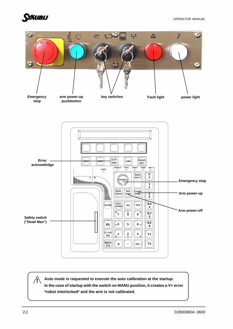
Emergencystop
arm power-uppushbutton
key switches power light
EDIT DISPCLRERR
CMD PROGSET
WORLD TOOL JOINT FREE DEV 2
MANHALT
COMPPWR
DISPWR
RUNHOLD
DONE NO YES
987
654
321
0 DEL. T2
T1
RZ6
RX4
RY5
Z3
Y2
DEVF3
J7-J12
F2
F1
SLOW
X1+--
PANIC
USER
REC
Erroracknowledge
Safety switch("Dead Man")
Emergency stop
Arm power-up
Arm power-off
Auto mode is requested to execute the auto calibration at the startup.In the case of startup with the switch on MANU position, it creates a V+ error*robot interlocked* and the arm is not calibrated.
Fault light

D28009604 - 0600 2.3
OPERATOR MANUAL
CHAPITRE 2 - ROBOT START-UP
2.1. INTRODUCTION
The robot can operate in two modes:
• Automatic mode:used to execute the production cycle, cell closed, nobody inside; arm movements are controlled by aprogram.
• Manual mode:used to move the arm with the manual control pendant (slow speed); the operator can enter the cell holdingthe manual control pendant.
2.2. CONTROL POWER-UP
• Check that the two key switches are set to (automatic mode) and (local mode).
• Set to 1 (ON) the general circuit breaker.
• Set to 1 (ON) display console (or start up PC for AdeptWindows PC interface).
Various messages will be displayed on the screen:• Loading… which indicates that the system is loading its memory.
• The system version numbers.
• Auto calibration… which performs absolute calibration of the arm.Throughout startup, the FAULT light is on.
Wait until “.” is displayed on the left of the screen indicating that controller startup is completed.
Automatic startup procedure:
In most cases, the application program is triggered automatically by an automatic startup procedure.
This procedure depends on the configuration of the cell (operator terminal or interface on PC).
2.3. ARM POWER-UP
2.3.1. AUTOMATIC MODE ( )
• On the controller, set key switch to .
• On keyboard, type ENABLE POWER (or EN PO) or press the COMP/PWR key on the manual controlpendant.
The “Press HIGH POWER button to enable power” message is displayed on the screen.
• On the controller, press the green button (flashing) within 15 seconds. The green button stays on.
If you have not pressed within 15 seconds, the pushbutton stops flashing and procedure must berepeated.

2.4 D28009604 - 0600
OPERATOR MANUAL
2.3.2. MANUAL MODE ( )
• On the controller, set key switch to .
• Take hold of the manual control pendant, press and hold the safety switch ("Dead man").
• Press the COMP/PWR key on the manual control.
The "Push, release, hold MCP enable switch" message is displayed on the screen.
• Within 10 seconds, release then repress and hold the safety switch.
The “Press HIGH POWER button to enable power” message is displayed on the screen.
• On the controller, press the green button (flashing) within 15 seconds. The green button stays on.
If you have not pressed within 15 seconds, the pushbutton stops flashing and procedure must be
repeated.
USE IN MANUAL MODE
When the safety switch (“Dead man”) is released, power to the arm is automaticallycut off.
To reactivate it, press and hold the safety switch, then press the COMP/PWR buttonon the manual control pendant.
Exceeding the assigned power-up times may trigger an aural signal and an error message may flash on themanual control pendant.
Before restarting the procedure, press the CLR ERR button. If required, do this several times until the light onthe key goes off.
2.4. CUTTING OFF POWER ON ARM
ROBOT's arm must be static and no robot programs must be in progress.
There are 5 possibilities:
1. switching on DIS PWR button of the teach pendant.
2. typing DISABLE POWER (DIS PO) on keyboard.
3. switching on the "ermergency stop" push button of the controller or of the teach pendant.
4. switching again on button when the ARM POWER indicator light is on.
5. modifying the switch position.
Cutting off power on arm in manual mode triggers an error on the manual control pendant that must beacknowledged (by pressing the CLR ERR key).

D28009604 - 0600 3.1
OPERATOR MANUAL
CHAPTER 3
TEACH PENDANT USE

3.2 D28009604 - 0600
OPERATOR MANUAL
EDIT DISPCLRERR
CMD PROGSET
WORLD TOOL JOINT FREE DEV 2
MANHALT
COMPPWR
STEPRUNHOLD
RECDONE NO YES
987
654
321
0 DEL. T2
T1
RZ6
RX4
RY5
Z3
Y2
DEVF3
F2
F1
SLOW
X1+--
PANIC
USER
CHAPTER 3 - TEACH PENDANT USE
Once the controller has been switched on, there are two ways to move the arm :- via the teach pendant- by running a program.
3.1. GENERAL
The controller allows the robot to be controlled from the optional teach pendant (also called manual controlpendant).
To use the pendant, place your left hand in the LH opening of the pendant by keeping the safety switch ("Deadman") pressed, and, using your left thumb, press the manual travel speed bars. Use your right hand for all theother functions. The various groups of keys will be explained in this section.
DISPWR
J7-J12F2

D28009604 - 0600 3.3
OPERATOR MANUAL
EDIT DISPCLRERR
CMD PROGSET
WORLD TOOL JOINT FREE DEV 2
MANHALT
COMPPWRSTEP
RUNHOLD
DONE NO YES
987
654
321
0 DEL. T2
T1
RZ6
RX4
RY5
Z3
Y2
DEVF3
F2
F1
SLOW
X1+--
PANIC
USER
REC
Userkeys
Predefiniedfunctionkeys
Mode's indicationLEDs
Modeselectionkeys
Manualcontrolkeys
Travel speedbars
SLOWkey(slow)
Liquid crystaldisplay (LCD)
Dataentrykeys
Programmablesfunctionkeys
3.2. PRESENTATION OF TEACH PENDANT KEYS
User LED
DISPWR
J7-J12F2
STEP

3.4 D28009604 - 0600
OPERATOR MANUAL
EDIT DISPCLRERR
CMD PROGSET
WORLD TOOL JOINT FREE DEV 2
MANHALT
COMPPWRSTEP
RUNHOLD
DONE NO YES
987
654
321
0 DEL. T2
T1
RZ6
RX4
RY5
Z3
Y2
DEVF3
F2
F1
SLOW
X1+--
PANIC
USER
REC
Userkey
3.2.1. USER KEYS
The user keys without set names under the LCD allow you to make the choices offered by the predefined functionkeys below or to choose an option in the menu displayed on the LCD by pressing the corresponding key duringthe execution of the application program.
DISPWR
J7-J12F2
STEP

D28009604 - 0600 3.5
OPERATOR MANUAL
EDIT DISPCLRERR
CMD PROGSET
WORLD TOOL JOINT FREE DEV 2
MANHALT
COMPPWRSTEP
RUNHOLD
DONE NO YES
987
654
321
0 DEL. T2
T1
RZ6
RX4
RY5
Z3
Y2
DEVF3
F2
F1
SLOW
X1+--
PANIC
USER
REC
Programmablefunctionkeys
Predefinedfunctionkeys
3.2.2. FUNCTION KEYS
The function keys allow you to start specific operations.There are two types: predefined and programmable.
The pendant has five predefined function keys used in conjunction with the operating system. These keys aredescribed below.
DISPWR
J7-J12F2
STEP
EDIT DISPCLRERR
CMD PROGSET
WORLD TOOL JOINT FREE DEV 2USER

3.6 D28009604 - 0600
OPERATOR MANUAL
EDIT function
The EDIT function key allows the location and real variables to be edited so that they can be modified, if applicable,by using the numerical teach pendant keys.
DISP function
The DISP function key is used to display on the teach pendant (from right to left in the figure below), the jointvalues, the values according to the WORLD location, the status of the system, the binary I/O status or the lasterror message.
CLR ERR function
Each time an error occurs, the pendant generates an audible warning, displays a flashing error message andswitches on the CLR ERR button LED. In manual mode, no other actions will be accessible while CLR ERRbutton LED is on.
Press the CLR ERR button to continue execution. The error message is deleted and the teach pendant returnsto the state it was in prior to the error.
EDIT DISPCLRERR
CMD PROGSET
WORLD TOOL JOINT FREE DEV 2USER
*PANIC BUTTON PRESSED*
EDIT DISPCLRERR
CMD PROGSET
WORLD TOOL JOINT FREE DEV 2USER
REAL LOC
SELECT DATA TO MODIFY
EDIT DISPCLRERR
CMD PROGSET
WORLD TOOL JOINT FREE DEV 2USER
JOINTVALUES
WORLDLOCATION STATUS
BINARYI /O
LASTERROR
* POWER DISABLED MANUAL/AUTO CHANGED *

D28009604 - 0600 3.7
OPERATOR MANUAL
CMD function
The CMD function key is used (from left to right in figure below) for automatic start, storing of complete memoryon disk (STORE ALL), or to activate the command programs CMD1 or CMD2) (loading, execution, saving).
PROG SET function
The PROG SET function key allows you to select a new program to be executed, set the number of start-up steps,set the number of program cycles to be executed, adjust the monitor speed and (or) initialize/start the applicationprogram resident in memory.
F1, J7-J12/F2, DEV/F3 keys
The three free programmable function keys (F1, F2 and DEV/F3) can be used by any application program forspecific needs (these keys are also used to control the external joints).
EDIT DISPCLRERR
CMD PROGSET
WORLD TOOL JOINT FREE DEV 2USER
STARTAUTO
CALIB ALLSTORE
CMD1 CMD2
EDIT DISPCLRERR
CMD PROGSET
WORLD TOOL JOINT FREE DEV 2USER
NEW STEP CYCLE SPEED START1 1 50
654
321
0 DEL. T2
T1
RZ6
DEVF3
F2
F1
STEP
J7-J12F2

3.8 D28009604 - 0600
OPERATOR MANUAL
3.2.3. DATA ENTRY KEYS
The data entry keys allow you to reply to messages displayed on the pendant LCD. These keys are: +/Yes, -/No, Del (delete), the numerical keys 0 to 9 and a decimal point.
REC/DONE key
The REC/DONE key behaves in the same way as the terminal keyboard -ENTER- key.When the LED of this key flashes and the data to be entered are keyed in, press the REC/DONE key to completedata entry. This key is also used to teach locations.
RECDONE NO YES
987
654
321
0 DEL. T2
T1
RZ6
RX4
RY5
DEVF3
F2
F1
SLOW
J7-J12F2
STEP
RECDONE NO YES
987
654
321
0 DEL. T2
T1
RZ6
RX4
RY5
DEVF3
F2
F1
SLOW
STEP
J7-J12F2

D28009604 - 0600 3.9
OPERATOR MANUAL
3.2.4. MODE SELECTION KEYS
The mode selection keys are the only pendant keys allowing you to change the robot arm movement mode.
EMERGENCY STOP button
The EMERGENCY STOP button stops the robot by deactivating the arm power supply (which activates thebrakes) and stops the program by creating a system error. This key must be used in case of emergency only.For easy identification, they are coloured red and yellow.
Regular use of this button (like all system emergency stops) will reduce the life of the motors.
WORLD TOOL JOINT FREE DEV 2
MANHALT
COMPPWR
STEPRUNHOLD Z
3
Y2
X1+--
PANIC
USER
WORLD TOOL JOINT FREE DEV 2
MANHALT
COMPPWR
STEPRUNHOLD Z
3
Y2
X1+--
PANIC
USER
DISPWR
DISPWR

3.10 D28009604 - 0600
OPERATOR MANUAL
WORLD TOOL JOINT FREE DEV 2
MANHALT
COMPPWR
STEPRUNHOLD Z
3
Y2
X1+--
PANIC
USER
WORLD TOOL JOINT FREE DEV 2
MANHALT
COMPPWR
STEPRUNHOLD Z
3
Y2
X1+--
PANIC
USER
RUN/HOLD key
The HOLD function of this key causes the immediate stop of the robot arm. The program sequence is interruptedand the message "HOLD" is displayed on the visual display unit.
Then if RUN/HOLD is pressed again, the cycle will continue while the key is pressed (AUTO mode on controlpanel).
DIS PWR key
Create a Disable Power as the monitor command.
DISPWR
DISPWR

D28009604 - 0600 3.11
OPERATOR MANUAL
COMP/PWR key
The PWR (POWER) function of this key is to authorize arm power-up (equivalent to ENABLE POWER).
The COMP (COMPUTER) function of this key is to authorize execution of programs.
When this button is pressed, the press button blinks and the system is waiting for an action on it (after15 seconds the system is desactived).
If the execution of a program is requested and the COMP/PWR key is inactive (MAN/HALT key activated),the *COMP MODE DISABLED* message is displayed on the terminal screen and the program is stopped.
MAN/HALT key
The MAN/HALT function of this key causes the immediate stop of the robot arm. The execution of the programis interrupted and the *COMP MODE DISABLED* message is displayed on the visual display unit.
The MAN function of this key is to enable selection of manual motion mode. In manual mode, all motioninstructions given via the system terminal keyboard have no effect on the robot arm (*COMP MODE DISABLED*message).
The manual mode is accessible only from the computer mode (COMP) and when the arm is powered. The systemremains in manual mode until ARM POWER is deactivated or the COMP/PWR key pressed.
WORLD TOOL JOINT FREE DEV 2
MANHALT
COMPPWR
STEPRUNHOLD Z
3
Y2
X1+--
PANIC
USER
DISPWR
WORLD TOOL JOINT FREE DEV 2
MANHALT
COMPPWR
STEPRUNHOLD Z
3
Y2
X1+--
PANIC
USER
DISPWR

3.12 D28009604 - 0600
OPERATOR MANUAL
The system is in WORLD mode when manual mode is pressed for the first time after switching on the system.Once in manual mode, press the MAN/HALT key successively to select required mode (WORLD —> TOOL —> JOINT —> FREE and return to WORLD). If you quit then return to manual mode (without switching off thecontroller), last activated status is automatically chosen.
NOTE : To comply with safety standards, the FREE MODE is no longer operative.
Use of all thes motion modes is described in paragraph 3.3
3.2.5. MANUAL CONTROL KEYS
The keys on the RH side are the manual control keys. Once in manual mode, these keys allow you to selectthe direction of each joint for manual motion: X/1, Y/2, Z/3, RX/4, RY/5, RZ/6. These keys are described laterin the robot motion modes.
Speed bars
The speed bars allow you to select the speed and manual motion direction. Robot motion is started by pressingthe speed bars with your left thumb. You can select a fast or slow speed in the two motion directions (+/-).
SLOW key
The SLOW key allows you to select between two different speed bar ranges. You can select a normal or veryslow travel speed.
RECDONE NO YES
987
RX4
RY5
SLOW
Fast
Fast Move direction
WORLD TOOL JOINT FREE DEV 2
MANHALT
COMPPWR
STEPRUNHOLD Z
3
Y2
X1+--
PANIC
USER
DISPWR
Slow

D28009604 - 0600 3.13
OPERATOR MANUAL
3.3. ROBOT MANUAL MOTION MODES
3.3.1. JOINT MODE
Joint motion is made around the axes of the various joints 1, 2, 3, etc. Rotational direction is given by the +or - speed bar keys.
3.3.2. FREE MODE
For safety reasons, the FREE key is no longer operational. To free the joints, use the brake release selectorlocated on the rear of the robot arm.
Motion aroundJoint 3

3.14 D28009604 - 0600
OPERATOR MANUAL
Motion of joint 3by User
1
RX RX 90
R
1
2
3.3.3. BRAKE RELEASE SYSTEM
The controller is power on. Put the button of joints selection (1) on the joint concerned. Make sure that the armand the load are well fixed in relation with this joint. Pressing the brake release push button (2), the selected jointis totally free. Take care to the fall of some axes under the gravity action. As soon as the button is released, themotor is braked again and the joint blocked.
The arm must then be supported manually.
Note: • Take care of joint 4 and 6 over rotation• Joint 5 is not reversible

D28009604 - 0600 3.15
OPERATOR MANUAL
3.3.4. COORDINATES SYSTEMS
3.3.4.1 PRELIMINARY
- To locate a point in space (3D), we use a coordinate system.
- The coordinate system is represented by origin and 3 axis called X Y Z all perpendicular "in between".
- The orientation of these 3 axis follows the "rule of the 3 fingers" of the RIGHT HAND.
Where X: Thumb X: Index finger
Y: Index finger OR Y: Middle finger
Z: Middle finger Z: Thumb
Example :
In the coordinate system REF 1:
- Location loc_a has for coordinates (4, 2, 5)
- Location loc_b has for coordinates (-2, 1, 0)
REF 1-2 0 4 X
1
2
5
Z Y
loc_b
loc_a
!!! Right hand !!! !!! Right hand !!!

3.16 D28009604 - 0600
OPERATOR MANUAL
Translation
A move in the direction of axis X will be called X+ and in the opposite direction of axis will be called X-. Samefor Y (Y+, Y-) and Z (Z+, Z-).
Rotation
RX represents a rotation around axis X.
To determine the sign of the rotation, when you do the move of rotation, if you screw on in the direction of theaxis X, you are doing RX+, else RX- (rule of the SCREW or CORK-SCREW). Same for Y (Y+, Y-) and Z (Z+, Z-
).
X
SCREW ON = RX+
X
UNSCREW = RX-

D28009604 - 0600 3.17
OPERATOR MANUAL
3.3.4.2. COORDINATE SYSTEM IN RX ROBOTS
WORLD Coordinate system (WORLD mode on the teach Pendant)
All translation motions are parallel to the WORLD coordinates. The RX, RY and RZ rotations are made withrespect to the WORLD coordinates. The motions are made by pressing the + or - speed bar keys.
TOOL Coordinate System (TOOL MODE on the teach Pendant)
All motions are parallel to the TOOL coordinates. Joint X is attached by the groove in tool attachment clamp.The RX, RY and RZ rotations are also made with respect to the TOOL coordinates. The motions are made bythe + or - speed bar keys.
Z+
Y+
X+
X-
Y+
X+ Z-
Z+
Z
X
Y
X+
X-
Y+
Y-
Z+
Z-
BASE CartesianCoordinate System
(WORLD fixed)

3.18 D28009604 - 0600
OPERATOR MANUAL
A point located in space will always be represented by 6 parameters, X, Y, Z, y, p, r.
- Value of X, Y, Z will be expressed in mm and represents the distance between the tool flange center and theorigin of the base Cartesian coordinates. These values represent the robot position.
- Value y, p, r will be expressed in degrees and represents the orientation of the local tool coordinates.
See definitions in Appendix (A2).
3.3.5. HOW TO VISUALIZE THE CURRENT POSITION OF THE ARM
Z+
Y+
X+ ZX
Y

D28009604 - 0600 3.19
OPERATOR MANUAL
WHERE
EFFECT Gives robot position and status of the hand at time when this command is declared.
SYNTAX WHERE value
If "value" given is none zero, the values are permanently displayed.Press ^C (Ctrl C) to stop it.
NOTE Points are displayed in Cartesian and revolute values.
EXAMPLE WHERE
Position % X Y Z y p r
base ref. in mm 45.53 35.28 -28.42 90 -85.32 17.427
Angular position Jt1 Jt2 Jt3 Jt4 Jt5 Jt6 Hand
in degrees -3.47 -85.983 84.728 -69.46 6.438 5.87 1.000

D28009604 - 0600 4.1
OPERATOR MANUAL
CHAPTER 4
EXECUTION AND CONTROL OF A PROGRAM
4.2 D28009604 - 0600
OPERATOR MANUAL
CHAPTER 4 - EXECUTION AND CONTROL OF A PROGRAM
4.1. HOW TO TRIGGER EXECUTION OF A PROGRAM
We will consider that the program was produced by an integrator or an in-house programmer, but, prior tothis, we will give the writing conventions that we will use throughout this document.
For reasons of simplicity, we will use BOLD UPPER CASE characters to describe the commands or instructions.Mandatory parameters will be given in bold lower-case characters.
Optional parameters will be given in ordinary lower case characters.
Example: EXECUTE prog name, number of loops, step EXECUTE PROG, 3, 2means that program name PROG is mandatory, but 3 and 2 are optional.
NOTE
Certain instructions may be entered with a minimum syntax.
For example, EXECUTE --> EX, EDIT --> ED
However, we request that this is only used after a certain amount of experience has been gainedin programming to avoid all ambiguities and interpretation errors.
To start a program, the following command is used:
EXECUTE prog name, number of loops, 1st loop step
Example: EX TOTO, 3, 4
We wish to execute the program TOTO, 3 times successively, (a negative number would lead to the executionof an unlimited number of loops) from program step No. 4, for execution of 1st loop only.
Example : EX TOTO, 1, 2
We require execution of TOTO program once only from step No. 2 (for first loop).
Example : EX TOTO, 1 or EX TOTO
Execution of program TOTO once only from step No. 1.
REMARK
If execution has already been performed once and you wish to execute the same program,simply enter EX.

D28009604 - 0600 4.3
OPERATOR MANUAL
The name of a program must always:
Start by a letter and never a number.Include a maximum number of 15 characters, alphabetical (a - z), digits (0 - 9), underlined characters (-), andpossibly points (.), and be entered as upper case or lower case characters. V+ language always displays programnames in lower case letters.
No other characters or spaces are permitted.
Example : Correct program name:TOTO.PROGTOTO.12TOTO_Num1
However, 1TOTO or TOTO+ is incorrectPI is incorrect (it is a key word).
The rules above are also valid for the names of the locations and realvariables etc.
Also, there is a risk that certain names may be confused with certain reservedwords which are given in the list that you can consult at the end of this manual.
Before triggering a program for the first time, comply with the followingconditions :- Prohibit all access to the area where the robot is working.- Always do a no-load simulation standing by to intervene on the emergency
stop pushbutton.- Perform the first cycles at slow speed (SP 2 to SP 15 depending on
application). You will always have the time to increase speed gradually.- Save your application program on disk or floppy.

4.4 D28009604 - 0600
OPERATOR MANUAL
We can mention here that there are two other system prompts; these are [*] and [?].The table below summarizes the three base indications.
Remark: Command mode includes a buffer of 15 commands which can be selected using the and keys on the keyboard.
Mode Action
.
*
Command
Execution
Indication given byrobot
Only commands of DIR, FDIR, FORMAT typeetc. can be given to the robot.
Commands of AB, PANIC type etc. canbe given.
Only editor instructions or commands canbe given (editor EDIT).
? Edit
It is possible to move from one MODE to another as follows :
COMMAND MODE(Mode by default)Used by ROBOT
(.)
EXECUTION MODE
(*)
EDITOR MODE
EX name.prog
Stop prog
Press F4 (for SEE) SEE name.prog

D28009604 - 0600 4.5
OPERATOR MANUAL
4.2. HOW TO ADJUST ROBOT SPEED
To specify on arm motion speed, you must use the SPEED command.
SYNTAX .SPEED value
"value" represents the robot maximum speed percentage(value must be between 1 and 100)
This speed adjustment is called “monitor speed”
EXAMPLE .SPEED 50 or SP 50.EXECUTE TOTO
Starts the TOTO program with arm motions limited to 50% of maximum speed.
NOTE
There is no need to stop execution of program in progress to modify arm motion speed.
Example .SPEED 10 command mode.EXECUTE TOTOSPEED 50 execution mode
Never specify a speed greater than the one recommended by the application.
NOTE
For certain applications (insertion, assembly, etc.), motions can be made at low speed inspite of a high monitor speed setting. Indeed, by program, a lower speed can be specified.

4.6 D28009604 - 0600
OPERATOR MANUAL
4.3. HOW TO EXECUTE A PROGRAM STEP BY STEP
By the following command:
XSTEP prog name, number of loops, Step
The description of the parameters and the action of this command are the same as the EXECUTE command thatwe discussed previously except that only one instruction is executed at the time.
To execute the next step, simply type X then hit the RETURN key.
PS : ® corresponds to hitting the - RETURN - key on the programming keyboard (or - ENTER - dependingon type of keyboard).
R
R
R
MOVE a
MOVE b
MOVE c
MOVE d
A
B
C
D
X
X
X
a
b
c
d

D28009604 - 0600 4.7
OPERATOR MANUAL
MOVE AMOVE B
Etc...
4.4. HOW TO FOLLOW THE EXECUTION OF A PROGRAM
In command mode (.), type the following command:
ENABLE TRACE (EN TRACE)
The various instructions will be displayed and scrolled on the screen as execution progresses. This allowsthe running of the program to be followed.
To return to normal mode, use the following command:
DISABLE TRACE(DIS TRACE)

4.8 D28009604 - 0600
OPERATOR MANUAL
4.5 HOW TO EXECUTE A SINGLE INSTRUCTION
EFFECT All the program instructions that we will examine can be executed in command modeif prefix "DO" is added.
SYNTAX DO instruction
NOTE If a DO instruction is given alone when a DO instruction has already been executed,the new DO will be equivalent to the previous DO.
EXAMPLE MOVE a can be executed in command mode, if you write:
DO MOVE a
Otherwise "illegal monitor command" will be displayed.
EXAMPLE DO b = (a * 4) / 7 + 4 - 2 ((3 + 8 - 2) / 4) - 3 (Return)
The result calculated immediately when - Return - key is pressed will be assigned tovariable b.
If DO (Return) is typed now, the machine will repeat all the calculations and assignthem to b thus avoiding retyping of the complete formula.

D28009604 - 0600 4.9
OPERATOR MANUAL
a
a
ABORT
b
STOP robotmotion
b
x
x
PANIC or HOLD
Immediate STOPof robot motion fromthe keyboard
4.6. HOW TO STOP A PROGRAM DURING EXECUTION
- Press the RUN/HOLD pushbutton on the teach pendant if you wish to immediatly stop the arm and the program,
or
- Enter ABORT via keyboard if stop is to be made at end of execution of instruction in progress,
or
- By typing PANIC via keyboard if immediate stop is required.
This command has the same function as pressing the MAN/HALT pushbutton.Under internal software control, it causes immediate stop in the robot motion and stops the execution programfrom the screen/keyboard.

4.10 D28009604 - 0600
OPERATOR MANUAL
4.7. HOW TO RESTART A PROGRAM
Two cases can occur.
4.7.1. STOP BY ABORT
Either RETRY or PROCEED can be used.
4.7.2. STOP BY RUN/HOLD OR MAN/HALT ON TEACH PENDANT
RUN/HOLD
a b
d c
a b
d c
ABORT
RETPRO
RET
PRO

D28009604 - 0600 4.11
OPERATOR MANUAL
4.8. MULTITASKS PROGRAMS
The V+ system is able to execute several tasks at the same time.7 tasks (0 to 6) are available in the standard version and 28 tasks (0 to 27) in the V+ extension version.The syntax of the declaration in multitasks functionning is the following:
By default num_task=0
EXECUTE num_task Program name, cycles, step
ABORT num_task
PROCEED num_task
RETRY num_task
Example : • EXECUTE traject
• EXECUTE 1 dialog
• EXECUTE 4 io_scrut
Task 0 Task 1 Task 4
traject is running dialog is running … io_scrut is running

4.12 D28009604 - 0600
OPERATOR MANUAL
STATUS
STATUS
EFFECT Gives the internal status of the robot, that is:- The program being executed,- Program step,- Number of cycles performed, task status, etc...
SYNTAX STATUS value
Where value can take value -1, 0 (or positive number)
Value at -1 :Status of all active tasks are displayed continually until CTRL+C is pressed.
Value at 0 (or positive) :Indications are shown once only.
NOTE If value is omitted, indications are shown once only.
EXAMPLE STATUS

D28009604 - 0600 4.13
OPERATOR MANUAL
KILL
TYPE Instruction or monitor command
EFFECT Clears the program execution stack and detaches any I/O devices that are attached.
SYNTAX KILL task.num
PARAMETER
task.num Integer specifying system task (0, 1, 2, etc.) to be activated. Default value: 0.
REMARK The KILL command is only valid when the specified program is not being executed(program terminated or aborted by ABORT task.num).

D28009604 - 0600 5.1
OPERATOR MANUAL
CHAPTER 5
EDITOR

5.2 D28009604 - 0600
OPERATOR MANUAL
CHAPTER 5 - EDITOR
5.1. PRELIMINARY
Before the editor of a program, a great time in developpement of an application is dedicated to the analysis of it.
The analysis will permit to write a well structured program, easier to read and understand and easier to maintain.
START
Definition of CLEAR ANDACCURATE specifications
FLOWCHART (desirable)
Edition of a program using a line orpage editor
EDIT or SEE
Correction of errors with helpfrom
DEBUGGERS functions
Morespecifications
?
END
Y
N
Triggering of program execution

D28009604 - 0600 5.3
OPERATOR MANUAL
5.2. HOW TO EDIT A PROGRAM
An editor allows you to : - Modify a program.- Insert new instructions.- Delete instructions.- Search for certain instructions, etc..
There are 2 editors : - A line editor: EDIT- A full-page editor: SEE
5.2.1. LINE EDITOR: EDIT
This editor is dealt with in the appendix for persons well acquainted with VAL language.
The LINE editor (EDIT prog.name) is less powerful than the PAGE editor (SEE prog.name), but it is the only editorwhich allows the robot to be placed in TEACH MODE.
The teach mode allows you to easily teach the robot a trajectory to be followed in its work envelope. To changeto teach mode, proceed as follows:
Enter EDIT prog.name
When in EDITOR MODE (?) type T name.location ®(or TS name.location ® to obtain the segments of the straight lines).
Record the instructions and the associated positions which make up the trajectory that the robot must reproduceby pressing the RECORD pushbutton on the teach pendant (REC/DONE).
To quit the teach mode, press - RETURN - and quit line editor by typing E ®

5.4 D28009604 - 0600
OPERATOR MANUAL
5.2.2. FULL-PAGE EDITOR: SEE
This editor has higher performances.
We shall now look at the main PAGE editor commands.
If you are in command mode (.), go to editing mode by entering:
SEE prog.name
If prog.name is not resident in system memory, you are asked to create it on the bottom of the screen.
«Prog.name» doesn’t exist. Create it ? Y/N
If you reply «Y», the program will be created and the SEE editor cursor will move towards the top of the editingwindow automatically entering the line specifying the program name.
. PROGRAM Prog.name ( )
and program creation can start.
If you reply «N» or press the - RETURN - key, you will return to the system and the named program will not becreated.
If «prog.name» is omitted, last edited or executed program is recalled.
ADVICE:
Try to avoid lines exceeding the editing window's width (80 columns), since the whole line will not be visible, andprogram flow and readability may be difficult to track.

D28009604 - 0600 5.5
OPERATOR MANUAL
Cursor
MONITOR
The following page editing window will be displayed:
; This is a comment
; You can write all your comments
; after a semi-colomn.
||||| list of instructions||||

5.6 D28009604 - 0600
OPERATOR MANUAL
REPLACEMode
INSERTMode
COMMANDMode
ESCKey
ESCKey
IKey
RKey
The SEE editor has three main editing modes : COMMAND, INSERT and REPLACE.
The COMMAND mode is the mode initially taken by the editor. In this mode, new program code is notentered, only special editor commands are active.
The INSERT mode allows new characters to be inserted into the program at the position where cursor isplaced. The cursor and existing codes move to the right of the screen.
The REPLACE mode allows existing text to be replaced by new text. The character entered replaces theone located above the cursor, the cursor moves to the right of the screen.
CHANGE OF MODE

D28009604 - 0600 5.7
OPERATOR MANUAL
1 2 3
4 5 6
7 8 9
0Enter
+
_/ *NumLook
NumLook
CapsLook
Scroll Look
InsertHome
Pg.Up.
Pg.Dn.EndDelete
Black Space
Enter
1 2 3
4 5 6
7 8 9
0Enter
+
_/ *NumLookInsert
HomePg.Up.
Pg.Dn.EndDelete
Shift
CurseurBall
Ctrl
Inserts a line on cursorline in insert mode.
Inserts a line on cursorline in insert mode.
Deletes character to left of cursor ininsert mode.
Del
This key must be inoff mode
Deletes a character at cursorlocation in all modes.
Deletes a character to right ofcursor in insert mode.
Note Other LINE EDITOR commands exist, they are given at the end of this manual (appendix).5.3. EDITING FUNCTION KEYS OF THE SEE EDITOR
5.3.1. CURSOR CONTROL

5.8 D28009604 - 0600
OPERATOR MANUAL
F1 F2 F3 F4
<F3>To create or edit theprogram called whencursor is on CALL instruction.
<F2>Creates a new program or allowsyou to enter the name of an existingprogram to be edited.
F9 F10 F11 F12
<shift-F9>Cuts line where cursoris located
<shift-F3>Search in editorprogram list
<shift-F10>Pastes buffer contents at cursorlocation
<F10>Pastes last line entered in buffer atcursor location
5.3.2. EDIT MULTIPLE PROGRAMS
<F9>Copies line where cursor islocated

D28009604 - 0600 5.9
OPERATOR MANUAL
5.3.4. TO QUIT EDITOR
Simply press key F4.
Caution: Make sure that buffer (copy, cut, paste) is empty.
For the robots equiped by a WYSE terminal, press <CTRL-E>, it means press simultaneously "CTRL"and on key E.
5.3.3. SEARCH, FIND AND REPLACE
5.3.5. EDITOR ENVIRONMENT PROBLEMS
Key to activate ordeactivate screen scroll
PrintScrn
Scroll Look Pause
If this task has already been used, then display is locked and a red band is displayed on top of the screen.
F4
F4
F5 F6 F7 F8
<F6>Cancels lastSearch Replace
<F8>RepeatsorRepeatsSearch Replace
<shift-F7>StartsSearch Replace
<F7>StartsSearch Find

5.10 D28009604 - 0600
OPERATOR MANUAL
Attempt to exit editor when buffer is not empty.When you have pressed function key F4, the following will be displayed :
To solve the problem, proceed as follows:
1. Enter number of attached lines
2. Press Ctrl + K
Attempt to change program_name with editor
Function key to solve problem

D28009604 - 0600 6.1
OPERATOR MANUAL
CHAPTER 6
DECLARATION OF VARIABLES ANDOPERATIONS ON MEMORY
6.2 D28009604 - 0600
OPERATOR MANUAL
Locations area(geographical locations of the various robots' positions)
Real Variable Area
Program area(Instructions)
String variable area(Alphanumeric messages)
Protected area inaccessibleto the user
SYSTEM and V+Language AREA
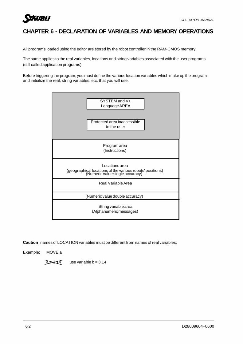
CHAPTER 6 - DECLARATION OF VARIABLES AND MEMORY OPERATIONS
All programs loaded using the editor are stored by the robot controller in the RAM-CMOS memory.
The same applies to the real variables, locations and string variables associated with the user programs(still called application programs).
Before triggering the program, you must define the various location variables which make up the programand initialize the real, string variables, etc. that you will use.
Caution : names of LOCATION variables must be different from names of real variables.
Example: MOVE a
a = 3.14 use variable b = 3.14
(Numeric value single accuracy)
(Numeric value double accuracy)
D28009604 - 0600 6.3
OPERATOR MANUAL
6.1 REAL VARIABLES
This consists of assigning an integer (eg: 123) or a real value (eg: 1.238) to a name.V+ considers that integrals are specific real value cases. INTEGERS must be between -16 777 216 and16 777 215.
Example : DO a = 12 (Monitor command)a = 12 means that 12 has been assigned to variable named a (Program instructions).
It also means that 12 is the content of variable a.
In the V+ case, the value must mandatorily be between:+/-3.4 * 1038 or under the "scientific notation" +/-3.4E + 38
The real values are stored with an accuracy of around 7 digits after the decimal point, however, rounding offgenerated by the computer must be taken into account.
Remember that, for example, 2.1 * 106 corresponds to the number 2 100 000 and 2.1 * 10-6 is equal to 0.0000021.
This type of notation is called the scientific notation.
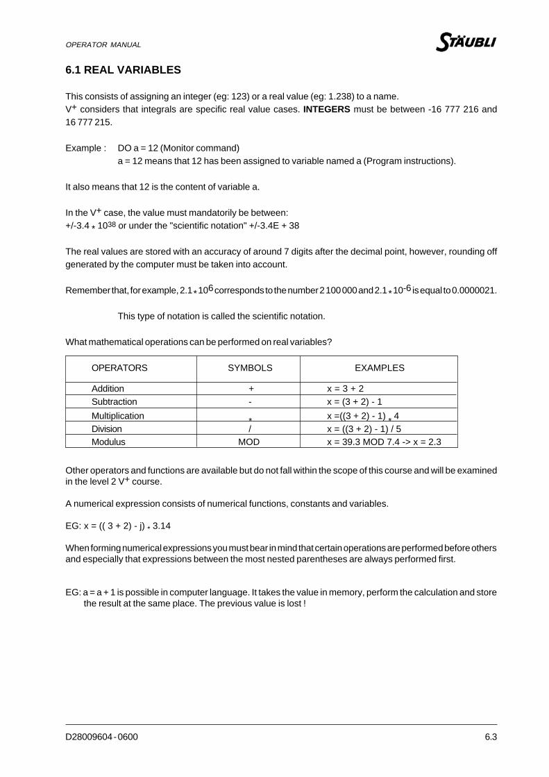
What mathematical operations can be performed on real variables?
OPERATORS SYMBOLS EXAMPLES
Other operators and functions are available but do not fall within the scope of this course and will be examinedin the level 2 V+ course.
A numerical expression consists of numerical functions, constants and variables.
EG: x = (( 3 + 2) - j) * 3.14
When forming numerical expressions you must bear in mind that certain operations are performed before othersand especially that expressions between the most nested parentheses are always performed first.
EG: a = a + 1 is possible in computer language. It takes the value in memory, perform the calculation and storethe result at the same place. The previous value is lost !
Addition + x = 3 + 2Subtraction - x = (3 + 2) - 1
Division / x = ((3 + 2) - 1) / 5Multiplication * x =((3 + 2) - 1) * 4
Modulus MOD x = 39.3 MOD 7.4 -> x = 2.3

6.4 D28009604 - 0600
OPERATOR MANUAL
6.2 STRING VARIABLES
A string of alphanumerical characters is assigned to a variable preceded by a $ (dollar).
SYNTAX $name = "alphanumerical characters"
EXAMPLE $reply = "reply by Yes or No"
NOTE The name of the variable following the "$" must not have more than 15 characters(other characters will be truncated without warning).Each variable name must start by a letter and can contain only letters, numbers,points and underlined characters.Characters can be entered in upper case and/or lower case, the system will displayand consider them as lower case characters.Avoid using names belonging to the list of keywords as variable names (see appendixat the end of the document).The content of a character string must not exceed 126 characters and must notcontain « characters (quotes to avoid confusion with delimiters).
WHAT OPERATIONS CAN BE PERFORMED ON STRING VARIABLES ?
Strings can be concatenated.
EXAMPLE $Total.1_compt = "All" + "Is" + "Well"...» will be equivalent to:$Total.1_compt = "All is well..."

D28009604 - 0600 6.5
OPERATOR MANUAL
6.3. LOCATION VARIABLES
6.3.1. CARTESIAN LOCATIONS / PRECISIONS LOCATIONS
A precision point is a location whose coordinates are not expressed in Cartesian coordinates (in mm withrespect to the X, Y, Z axes, etc.) but in degrees with respect to an absolute position specific to each joint.
It is recognized or declared as a precision point when # is added in front of the location name.
Example : #a and a are two separate locations.
One is defined in angular coordinates (#a).
The other is defined in Cartesian transform coordinates (a).
JT1 18° X 120 mmJT2 -123° Y 12 mm
#a JT3 +14° a Z 5 mmJT4 90° y 90°JT5 -90° p -90°JT6 0° r 0°
The advantages of precision points are :
Precision points describes the configuration of the arm.Precision points prevent axis alignment problems on 6-axis robots (singularity).
The disadvantages of precision points are:
No correlation with the metric system as dimensions are not expressed in mm.
6.3.2. DEFINE A LOCATION IN MONITOR COMMAND MODE
For this, use the POINT variable.name command
Example: POINT a (Return)
CHANGE ? 10,30, - 15,18 (Return)
CHANGE ? (Return)
You have assigned dimensions X, Y, Z, etc. to a location named a.
This instruction is only active in command mode.
This instruction is also available for precision locations.
Example: Definition of the TOOL transformation.
X/JT1 Y/JT2 Z/JT3 y/JT4 p/JT5 r/JT60 0 0
X/JT1 Y/JT2 Z/JT3 y/JT4 p/JT5 r/JT610 30 -15 18
0 0 0
0 0

6.6 D28009604 - 0600
OPERATOR MANUAL
6.3.3. HOW TO MOVE THE TOOL REFERENCE SYSTEM
Why move the tool frame to the tool extremity ?
It is always good practice, during an industrial application, to position the tool coordinates not at the centre ofthe tool flange (default setting), but to the end of the tooling:
- It makes the teaching of locations easier: minimize the manual motion operations;
- It allows to control the position and the speed of trajectory at the tool extremity;- When using a cutting tool, it's easier to correct its geometrical characteristics than to teach again all
locations of the application.
If the geometrical and dimensional characteristics of the tool to be fitted to the end of the wrist are known, it willbe easy to move the tool coordinates with the following instruction...
D28009604 - 0600 6.7
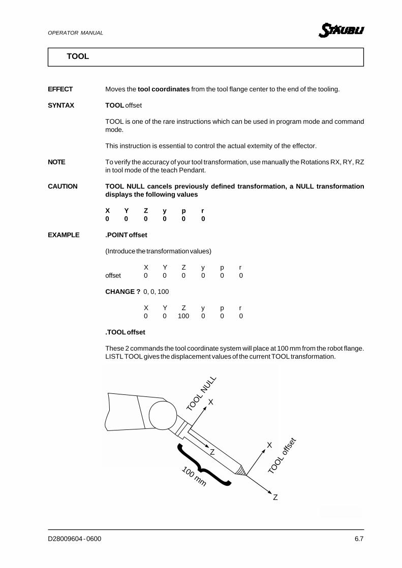
OPERATOR MANUAL
TOOL
EFFECT Moves the tool coordinates from the tool flange center to the end of the tooling.
SYNTAX TOOL offset
TOOL is one of the rare instructions which can be used in program mode and commandmode.
This instruction is essential to control the actual extemity of the effector.
NOTE To verify the accuracy of your tool transformation, use manually the Rotations RX, RY, RZin tool mode of the teach Pendant.
CAUTION TOOL NULL cancels previously defined transformation, a NULL transformationdisplays the following values
X Y Z y p r0 0 0 0 0 0
EXAMPLE .POINT offset
(Introduce the transformation values)
X Y Z y p roffset 0 0 0 0 0 0
CHANGE ? 0, 0, 100
X Y Z y p r0 0 100 0 0 0
.TOOL offset
These 2 commands the tool coordinate system will place at 100 mm from the robot flange.LISTL TOOL gives the displacement values of the current TOOL transformation.
100 mmX
ZX
Z
{100 mm
TOO
L NULL
TOO
L of
fset

6.8 D28009604 - 0600
OPERATOR MANUAL
6.3.4. HOW TO DEFINE A LOCATION BY TEACHING
Move the robot to the required position and enter via keyboard :
HERE a (Return)
CHANGE ? (Return)
When the RETURN key is pressed, the current robot arm position coordinates are assigned to location a.
This command is also available for precision locations: HERE #start
Unlike POINT, the HERE instruction is active both in command and program modes.
X/JT1 Y/JT2 Z/JT3 y/JT4 p/JT5 r/JT6120 12 -80 85 -40 0
D28009604 - 0600 6.9
OPERATOR MANUAL
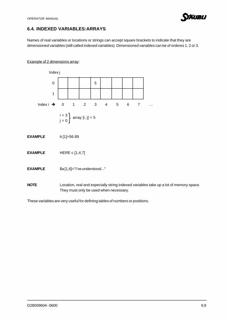
6.4. INDEXED VARIABLES:ARRAYS
Names of real variables or locations or strings can accept square brackets to indicate that they aredimensioned variables (still called indexed variables). Dimensioned variables can be of orderes 1, 2 or 3.
Example of 2 dimensions array:
Index j
0 5
1
Index i � 0 1 2 3 4 5 6 7 …
i = 3 }j = 0 array [i, j] = 5
EXAMPLE b [1]=56.89
EXAMPLE HERE c [1,4,7]
EXAMPLE $a [1,6]="I’ve understood..."
NOTE Location, real and especially string indexed variables take up a lot of memory space.They must only be used when necessary.
These variables are very useful for defining tables of numbers or positions.

6.10 D28009604 - 0600
OPERATOR MANUAL
We can see that :
The first index between square brackets represents position in height.The second index represents the width.The third index represents the depth.
This makes it very easy to locate a packet on a pallet.
Also, a variable or a mathematical expression can be used for the index instead of a numerical value whichcan sometimes make the program easier to write.
C 3,1,1
C 2,1,1
C 1,1,1
C 3,2,1
C 2,2,1
C 3,3,1
C 2,3,1
C 1,3,1
C 1,2,1
C 3,3,2
C 1,3,2
C 2,3,2

D28009604 - 0600 6.11
OPERATOR MANUAL
TEACH
TYPE Monitor Command
EFFECT Very useful and fast for teaching a lot of locations along a trajectory
SYNTAX TEACH loc.name[index]
NOTE index can take any positive integer value
EXAMPLE TEACH traj[ ] (RETURN)
The REC/DONE key is blinking on the teach Pendant :
Each time you press the REC/DONE key, the system memorises the location. The index isautomatically increased at each memorization.
X/J1 Y/J2 Z/J3 y/J4 p/J5 r/J6
traj[0] _ _ _ _ _ _
traj[1] _ _ _ _ _ _
traj[2] _ _ _ _ _ _
To exit from teaching, just press ENTER key on the keyboard.
traj [0]
traj [4]
traj [10]

6.12 D28009604 - 0600
OPERATOR MANUAL
6.5. MEMORY OPERATIONS
The following monitor commands will be very useful to manage the system and debug programs.
D28009604 - 0600 6.13
OPERATOR MANUAL
.DIRTOTO
TITI
TUTU
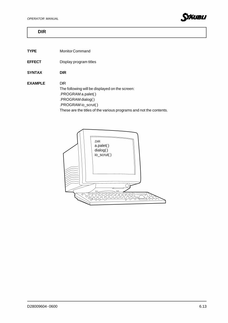
DIR
TYPE Monitor Command
EFFECT Display program titles
SYNTAX DIR
EXAMPLE DIRThe following will be displayed on the screen:.PROGRAM a.palet( ).PROGRAM dialog( ).PROGRAM io_scrut( )These are the titles of the various programs and not the contents.
a.palet( )dialog( )io_scrut( )
6.14 D28009604 - 0600
OPERATOR MANUAL
LIST
TYPE Monitor Command
EFFECT Display memory contentsThis can only be done in command mode (.)
SYNTAX LISTP to display program contents.
EXAMPLE LISTP prog3, paintwill display on screen:
.PROGRAM prog3()1 MOVE a2 MOVE b.END
.PROGRAM painting()1 MOVE k2 MOVE g.END
SYNTAX LISTL to obtain a display of various location coordinates.
EXAMPLE LISTL #a,b,c, etc..
SYNTAX LISTR to obtain content of real variables.
EXAMPLE LISTR x,y,z, etc..
SYNTAX LISTS to display string variables.
EXAMPLE LISTS $name, $toto
LISTP TITI.Program TITI
MOVE A
MOVE B
.END
prog3painting
ab
D28009604 - 0600 6.15
OPERATOR MANUAL
NOTE: TERMINAL CONTROL CHARACTERS
(Screen-Keyboard)
These control characters are operative when the CONTROL key and the corresponding alphanumeric keyare pressed. They facilitate reading of programs on screen.
EXAMPLE For ^C, simply press the "CTRL" key and the C key.
- ̂ C Stops execution of DIRECTORY, LISTP, STORE instructions, etc., but not theexecution of the program in progress.
- ̂ S Stops scrolling of a program on display.or SCROLL lock key
- ̂ Q Restarts scrolling interrupted by ̂ S.
- ̂ W Slows down scrolling to make contents easier to read.A second ̂ W will return you to previous state.
NOTE The codes above are not active on all terminals.
}

6.16 D28009604 - 0600
OPERATOR MANUAL
(Le programme TUTU existe toujours)
Mémoire Centrale
TUTU Program
TOTO Program(The TUTU program still exists)
COPY
TYPE Monitor Command
EFFECT Copy programs
SYNTAX COPY new prog name = old prog name
EXAMPLE COPY TOTO = TUTU
You will obtain a copy of the TUTU program called TOTO.
Primary storage

D28009604 - 0600 6.17
OPERATOR MANUAL
Mémoire Centrale
(Le programme TUTU n'existe plus)
RENAME
TYPE Monitor Command
EFFECT Rename programs, locations, real variables, etc
SYNTAX RENAME new prog name = old prog name
EXAMPLE RENAME TOTO = TUTU
After this instruction has been executed, TUTU PROG is called TOTO.
Primary storage
TUTU program
TOTO program(TUTU program no longer exists)

6.18 D28009604 - 0600
OPERATOR MANUAL
Mémoire Centrale
DELETEP Prog1,TITI
DELETE
TYPE Monitor Command
EFFECT Delete programs, locations, real, variables, etc
SYNTAX DELETE prog 1 [,..., prog n] for programs, locations, associated variables.
EXAMPLE DELETE prog1,TITI, etc.
SYNTAX DELETEP prog 1 [,..., prog n] for programs,
EXAMPLE DELETEP TOTO will delete TOTO.PG
SYNTAX DELETEL locations [,...locations] for locations.
EXAMPLE DELETEL A,#P1, B6
Deletes location A, #P1 and B6.
SYNTAX DELETER real variable [,..., real variable] for real variables.
EXAMPLE DELETER C,D,A[1].
If we had simply written A [ ], all A[1], A[2],..., A[n] dimensioned variables would havebeen deleted.
SYNTAX DELETES string 1,[,...,] for strings.
EXAMPLE DELETE $A,$YU
Primary storage
Prog 1 program
DELETEP Prog1, TITITITI program

D28009604 - 0600 6.19
OPERATOR MANUAL
x x x x . PG PROGRAMS AREA
x x x x . LC POINTS AREA
ProtectedareaV+
x x x x . DB DOUBLE REALS AREA
x x x x . ST STRINGS AREA
x x x x . RV REALS AREA
ZERO
TYPE Monitor Command
EFFECT Dumps total memory contents and external inputs/outputs.
SYNTAX ZERO
The machine will reply : ARE YOU SURE (Y,N) ?
NOTE ZERO obviously cannot be incorporated into an Autostart program.

D28009604 - 0600 7.1
OPERATOR MANUAL
CHAPTER 7
SOME MOTION PROGRAM INSTRUCTIONS

7.2 D28009604 - 0600
OPERATOR MANUAL
MOVE
EFFECT This instruction commands the robot to move to an indicated location along a trajectorynot imposed by the user.
SYNTAX MOVE location.name
EXAMPLE
NOTE The V+ software is based on a multitasking structure.
The software executes, in parallel, an application program including robot arm motions and an input/outputmanagement calculation program.
Also, during execution of the various motion instructions, the robot will not wait for the end of the motion inprogress to analyze and execute mathematical operations, input/output operations, etc. This may lead, ifcare is not taken, to the execution of unexpected motion instructions.
Hence, caution :
In the V+ software, remember that if instructions which do not make reference to motions are insertedbetween motion instructions, these will be executed in parallel with the motion.
EXAMPLE MOVE a1MOVE a2x = h + 34.56 ;Calculation instructionSIG 1 ;Instruction setting output No. 1 to logic 1t = x + 56 ;Calculation instructionMOVE b...
MOVE b
a
b

D28009604 - 0600 7.3
OPERATOR MANUAL
We can see that instructions x, SIG 1, t will be executed during motion to point a2.
If simultaneous operation is not required, insert a BREAK instruction (see trajectory control chapter).
Hence :MOVE a1MOVE a2 ;Motion instructionBREAKx = 34.56 ;Calculation instructionSIG 1 ;Instruction setting output No. 1 to logic 1t = x + 56 ;Calculation instructionMOVE b

7.4 D28009604 - 0600
OPERATOR MANUAL
MOVES e
A
B
MOVES
EFFECT This instruction commands the robot to move to location along a straight line trajectory.
SYNTAX MOVES location.name
NOTE A straight line movement is not the fastest motion despite the fact that the path isthe shortest.
EXAMPLE
e
a

D28009604 - 0600 7.5
OPERATOR MANUAL
X
X
50 mm
MOVE A
Ax e Z
OU
T IL
APPRO 1,50
APPRO
EFFECT This instruction, generally followed by MOVE, allows the robot to approach location by avalue in mm along tool Z-axis.
SYNTAX APPRO location.name, distance
NOTE The axis assigned to the distance will always be the tool Z-axis
EXAMPLE APPRO a,50
TOOL Z-Axis
A
MOVE a
a
APPRO a,50
TOO
L Z-Axis

7.6 D28009604 - 0600
OPERATOR MANUAL
APPROS
EFFECT Same as previous instruction but location A approach is made along a straight line.
SYNTAX APPROS location.name, distance
NOTE The axis assigned to the distance will always be the tool Z-axis
EXAMPLE APPROS a,50
Straight line approach
APPROS a,50
50 mm
MOVE a
a
TOO
L Z-axis

D28009604 - 0600 7.7
OPERATOR MANUAL
50 mm
X
Ax e Z O
UT
IL
Etc...
DEPART 50
DEPART
EFFECT This instruction performs the opposite function to the APPRO instruction. It allows therobot to move from the point where it was located during the execution of the DEPARTinstruction, moving along the tool Z-axis by a value given in mm.
SYNTAX DEPART distance
NOTE The axis assigned to the distance will always be the tool Z-axis and movement will bemade in relation to the position that the robot occupies at time when this instruction isexecuted.
EXAMPLE DEPART 50
TOOL Z-axis
TOO
L Z-axis

7.8 D28009604 - 0600
OPERATOR MANUAL
50 mm
DEPARTS 50
DEPARTS
EFFECT Same as previous instruction, but movement will be made along a straight line.
SYNTAX DEPARTS distance
NOTE The axis assigned to the distance will always be the tool Z-axis
EXAMPLE DEPARTS 50
Straight linedepart
TOOL Z-axis

D28009604 - 0600 7.9
OPERATOR MANUAL
OPENI, CLOSEI
EFFECT Robot solenoïd instructions.
SYNTAX OPENI Immediate opening of pneumatic jaws.
CLOSEI Immediate closing of pneumatic jaws.
NOTE 50 ms delay by default.
EXAMPLE MOVE aOPENI ;Immediate opening with breakpoint.MOVE bCLOSEI ;Immediate closing with breakpoint....
Delay of several secondsbefore motion restarts
AMOVE A
MOVE B
B
a
b
b
a

7.10 D28009604 - 0600
OPERATOR MANUAL
OPEN, CLOSE
EFFECT Gripper motions instruction jaws.
SYNTAX OPEN Opening of pneumatic jaws
CLOSE Closing of pneumatic jaws.
NOTE It is often preferable to use OPENI, CLOSEI to be sure that there is a breakpointensuring a certain stability in the grip.
EXAMPLE MOVE aOPEN ;Opening during motion to point B without breakpointMOVE bCLOSE ;Closing of jaws...
No stop in motion
A
MOVE A
MOVE B B
a a
b b

D28009604 - 0600 7.11
OPERATOR MANUAL
DELAY
EFFECT Stops the robot for the time stipulated in the instruction. This time must be given inseconds and cannot be less than 16 ms.
SYNTAX DELAY time
NOTE The delay is generated in software form.
CAUTION The DELAY instruction must be considered as a motion instruction to go nowhere.
EXAMPLE MOVE aBREAKDELAY 180BREAKMOVE b...
Wait 180 seconds
EXAMPLE c = 2MOVE aBREAKDELAY 30BREAK ;for b=3+c to be executed at the end of temporizationb=3+cMOVE f
MOVE bMOVE a ax
b
7.12 D28009604 - 0600
OPERATOR MANUAL
BREAK
EFFECT Switches to DISABLE CP mode only for the next motion instruction. It suspends executionof the program until the motion has reached its destination.
SYNTAX BREAK
NOTE BREAK is prefered to avoid execution of calculation and input/output managementinstructions, etc. (other than motion instructions) located between two locations.
EXAMPLE MOVE aMOVE b ;Breakpoint on bBREAK ;as breakpoint recognized during motion to bMOVE cMOVE d
NOTE Use of this instruction is mandatory to observe the wait time with the DELAY instruction.

D28009604 - 0600 7.13
OPERATOR MANUAL
TYPE
EFFECT This instruction is used to display a message on the screen during the execution of aprogram and/or display the content of one or more declared variables.
SYNTAX TYPE control character, "message","variable",{etc.}
EXAMPLE TYPE /B, "VALUE OF x =",x
will display value of x = 3 if content of variable x is equal to 3 and terminal bell willsound.
Some of the most useful control characters are listed below:
/B Rings terminal bell;
/Cn Causes n line skips (n times CR and n times LF);
/S No line skips (no CR’s or LF’s);
/Un Moves cursor up n lines.
/Xn Moves cursor n spaces to the right.
CAUTION Control characters do not operate on all terminals.
EXAMPLES TYPE /C3, /B, "Hello"
TYPE /X30, "Hello"<— 30 spaces —> Hello…
NOTE If TYPE includes no parameters, a blank line is generated.

7.14 D28009604 - 0600
OPERATOR MANUAL
PROMPT
EFFECT This instruction is used to enter values assigned to variables via the keyboard.
SYNTAX PROMPT "MESSAGE", VARIABLE
The program will be suspended until the operator replies.
The reply can be a real variable or variables and/or a string of characters.If the user replies to several parameters, these must be separated by a comma.
NOTE Avoid requesting several values. It is preferable to request different values one afterthe other.
EXAMPLE 1 PROMPT "Give me the length of part", length.
EXAMPLE 2 PROMPT "Give me the programmer’s name",$name
EXAMPLE 3 PROMPT "Enter + to increase or - to dicrease:", $ans
IF ($ans == "+") THENdistance = distance + 1
END
IF ($ans == "-") THENdistance = distance - 1
END

D28009604 - 0600 8.1
OPERATOR MANUAL
CHAPTER 8
DIGITAL INPUTS AND OUTPUTS

8.2 D28009604 - 0600
OPERATOR MANUAL
CHAPTER 8 - DIGITAL INPUTS AND OUTPUTS
8.1 EXTERNAL OUTPUTS (on/off)
These outputs are still called DIGITAL outputs.
Number depends on options selected when purchasing robot (256 max.).
Their addresses are as follows:
1—> output No. 1
2—> output No. 2
3—> output No. 3
4—> output No. 4
etc... until 8 in standard version.The 7 and 8 outputs are used by default by the solenoid valves of the ROBOT arm.
Programming of outputs :
SIG 1, -2,...,8
RESET
RUNSIG
SIGNAL val1, val2, val3, ...
With different values which can be constants, variables or mathematical expressions.
We shall now look at each of these instructions.
+ -
D.C. SUPPLY
OUTPUT N°1
BASIC I/O
01-
01+
SIG1
WIRING DIAGRAM
24 V 0 V

D28009604 - 0600 8.3
OPERATOR MANUAL
SIGNAL
EFFECT Activates the contact of an external digital output.
SYNTAX SIG output1, output2,...
NOTE The outputs remain as such until a new SIG instruction cancels the corresponding output.
This instruction operates in command mode and program mode.
EXAMPLE SIG 2, -1, 4
Outputs No. 2 and No. 4 will change to logic 1 and output No. 1 will change to logic 0.
EXAMPLE Sucker = 2Grip1 = 1Grip2 = 4SIG Sucker,-(Grip1),Grip2
This example sets up same condition as previous example.
EXAMPLE FOR OUTPUT = 1 TO 8SIG OUTPUTDELAY 1BREAK
END...
In this case, outputs between 1 and 8 will pass to logic 1 in a sequence delayed by a onesecond interval.
24 V 0 V
ROBOT SIG1 Action

8.4 D28009604 - 0600
OPERATOR MANUAL
BEFORE
AFTER
Output 1
Output 1
Output 5
Output 5
RESET
EFFECT Resets all outputs.
SYNTAX RESET
NOTE Switching off the controller also resets all outputs.
This instruction operates in command mode and program mode.
EXAMPLE SIG 1,5RESET Outputs 1 to 5 (and the other outputs at 1) will be reset
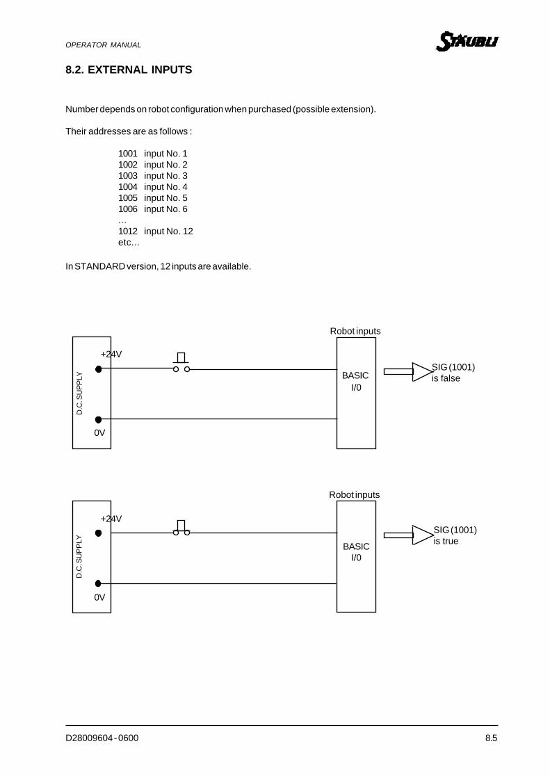
D28009604 - 0600 8.5
OPERATOR MANUAL
8.2. EXTERNAL INPUTS
Number depends on robot configuration when purchased (possible extension).
Their addresses are as follows :
1001 input No. 11002 input No. 21003 input No. 31004 input No. 41005 input No. 51006 input No. 6...1012 input No. 12etc...
In STANDARD version, 12 inputs are available.
SIG (1001)is false
SIG (1001)is true
+24V
+24V
Robot inputs
0V
0V
D.C
. SU
PPLY
D.C
. SU
PPLY
BASICI/0
BASICI/0
Robot inputs
8.6 D28009604 - 0600
OPERATOR MANUAL
IO
TYPE Monitor command
EFFECT Displays the current states of the external binary input/output signals and/orthe internal software signals.
SYNTAX IO sig_group
PARAMETERS
sig_group Integer which, if specified, selects the binary signals to be displayed.
0 Display of binary output signals.
1 Display of binary input signals.
2 Display of system software signals.
EXAMPLES
Dashes Signal not configured.
0 Low signal
1 High signal

D28009604 - 0600 8.7
OPERATOR MANUAL
Motion to a
button (1001)pressed ?
Motion to b
NO YES
WAIT...
EFFECT This instruction will interrupt the program until corresponding expression is valid.
SYNTAX WAIT <condition>
If the result of the operation is «0», the machine considers that the result is false.For all other values, the result will be considered as true.
NOTE Inputs, outputs, variables, etc. can be tested.
EXAMPLE WAIT SIG(1001,-1003,1002)
EXAMPLE WAIT (SIG(1001,-2) OR SIG(1008))
EXAMPLE MOVE aWAIT SIG(1001)MOVE b...

D28009604 - 0600 9.1
OPERATOR MANUAL
CHAPTER 9
DISKETTE OR DISK SAVING OPERATIONS

9.2 D28009604 - 0600
OPERATOR MANUAL
CHAPTER 9 - DISKETTE OR DISK SAVE OPERATION
9.1 WHY YOU SHOULD USE A DIRECTORY
On account of their high capacities, diskettes or hard disks can contain a high number of files.
If all file names are conserved in a single list, searching for a file may take a long time.By grouping files of the same type or those relevant to a given theme into subdirectories, you can reduce thetime required to locate a given file. Also, deletion of a "PART1.V2" file in a given directory will not delete the same"PART1.V2" file located in another directory.
RECOMMENDATIONS
Always try to place files of a given application in the same directory.Various commands will allow you to create, delete and select directories. We will look at these later.
9.2 WHY YOU SHOULD SAVE PROGRAMS
Although the memory is saved, when a program has been written, it should always be saved to avoid having toreconstruct it again at a later stage.Saving is made under a file name defined by the user.
The meanings of the suffixes displayed after the file names are as follows:PRO_NAME.XXX where XXX —> suffix
EXAMPLE TOTO.PG for application filesTOTO.LC for location filesTOTO.RV for real variable filesTOTO.DB for long real variable filesTOTO.ST for string filesTOTO.V2 for all of the above files.
ASSIGNMENT of a PHYSICAL unit.
The standard version includes a Compact Flash. However, optionally, a second"3-1/2" drive can be added.
The V+ language operating system uses designations "A:", "B:", "C:", "D:"
The standard 3-1/2" disk drive is called "B:".The standard hard disk is called "D:".
When the controller is switched on, the system goes to "D:" by default.
However, the DEFAULT DISK command can be used to temporarily assign required unit or path.
EXAMPLE DEF D = B:DEF D = D:\program\toto\

D28009604 - 0600 9.3
OPERATOR MANUAL
9.3 COMMANDS ASSOCIATED WITH COMPACT FLASH OR FLOPPY DISK DRIVE
1. FDIRECTORY
2. DEF D =… OR CD
3. STORE, STOREP, STOREL, STORER, STORES…
4. LOAD
5. FDIRECTORY/C
6. FDIRECTORY/D
7. FLIST
8. FCOPY
9. FDELETE
10. FRENAME

9.4 D28009604 - 0600
OPERATOR MANUAL
FDIRECTORY
TYPE Monitor command
EFFECT Displays the files contained on the disk and the available storage space.
SYNTAX FDIRECTORY
The system gives the following:NameSuffixNumber of sectors that the file takes up.Codes of special attributes.Date and time when file was recorded.
NOTE Attribute «P» indicates that the file can be executed, but not edited, displayed ortraced during execution, also, the programs cannot be transferred to disk.Attribute «R» indicates that the file can be loaded into the memory and that programcontents can be executed and displayed. The programs cannot however be edited orsaved on disk.Attribute «D» indicates a directory.
EXAMPLE FDIRECTORY TOTO.*
Displays the information of all TOTO files (TOTO.PG, TOTO.LC, etc.) on the disktaken by default and the current directory.
Generic characters can be used, for example, if FDIRECTORY f* is written, all files starting by f will be displayed.
F DIRDirectory of a:
ALI.V2 26-Mar.93 09:31
ALO.V2 21-Apr.93 04:31
ALA.V2 21-Mar.93 09:32
1281/2847 Sectors
FDIR

D28009604 - 0600 9.5
OPERATOR MANUAL
TOTO TITI
D : \
DEF D =... or CD
TYPE Monitor command
EFFECT Changes the directory, or disk unit and/or diskette.
SYNTAX DEF D=D:\Directory1\Directory2\etc...or CD Directory 1
EXAMPLE DEF D=D:\toto\titi\
NOTE DEF D=.. moves you back one directory path (adjacent directory).
EXAMPLE You are in directory D:\TOTO\TITI\DEF D=.. will transfer you to directory D:\TOTO\
REMARK From the recent V+ language versions, the command cd.. is accepted to ensurecompatibility with DOS.
Also: cd D:\TOTO\TITI
cd (or def) also enable to visualize the default directory.

9.6 D28009604 - 0600
OPERATOR MANUAL
STORE, STOREP, STOREL, STORER, STORES...
TYPE Monitor command
EFFECT Stores the programs in the robot’s RAM memory and the associated variables onto disk file.
SYNTAX STORE File=Prog1,prog2,...,Prog n
If no program is specified, all programs, variables and associated subprograms are loadedonto disk file.
Use STOREL to save locations onlySTOREP for programsSTORER for real variablesSTORES for strings
NOTE You should not create files with the ".BN*" extension.
STORER generates an xxx.RV and/or xxx.DB file following type of real variables encounteredin the various programs.
EXAMPLE STORE FICHE=PROG1,...,PRG6
NOTE The system saves the subprograms associated with the calling programs, it saves all thatis required to run the application...
STÄ
UB
LI
CPU
RO
BO
T M
EMO
RY
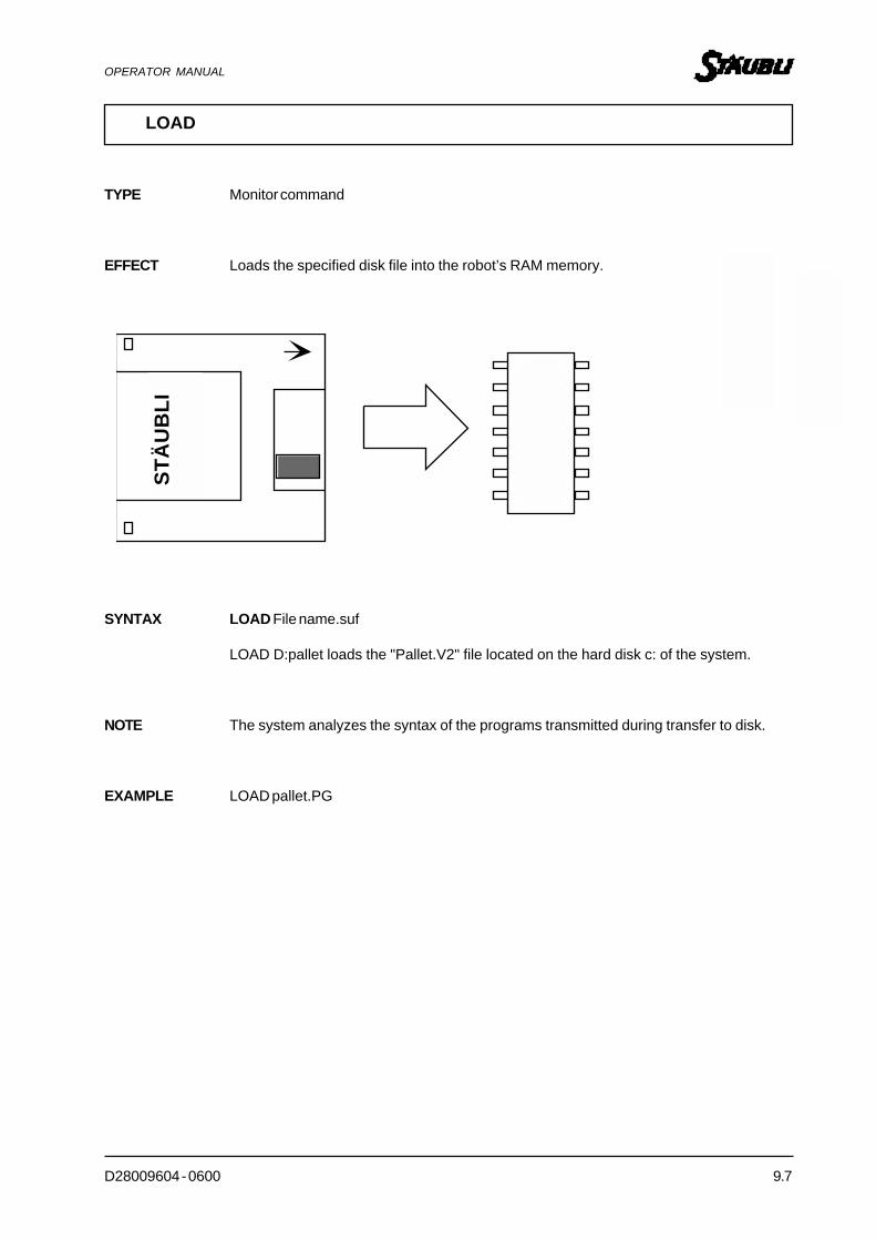
D28009604 - 0600 9.7
OPERATOR MANUAL
LOAD
TYPE Monitor command
EFFECT Loads the specified disk file into the robot’s RAM memory.
SYNTAX LOAD File name.suf
LOAD D:pallet loads the "Pallet.V2" file located on the hard disk c: of the system.
NOTE The system analyzes the syntax of the programs transmitted during transfer to disk.
EXAMPLE LOAD pallet.PG
STÄ
UB
LI
Rob
ot's
CPU
mem
ory

9.8 D28009604 - 0600
OPERATOR MANUAL
c : Main directory (Root directory)
Spoon Fork
Curved Straight
Spoon Fork
Sanding
FDIRECTORY/C
TYPE Monitor command
EFFECT Creates a directory from the current directory.
SYNTAX FDIR/C
EXAMPLE To define "Spoon" directory in "Deburr" branch
FDIR/C D:\DEBURR\ (if «Deburr» directory does not exist)
and then:FDIR/C D:\DEBURR\SPOON\
Deburr

D28009604 - 0600 9.9
OPERATOR MANUAL
FDIRECTORY/D
TYPE Monitor command
EFFECT Deletes a directory from current directory.
SYNTAX FDIR/D
EXAMPLE FDIR/D D:\TOTO\TITI\TUTU\Directory TUTU will be deleted.
D : \
TOTO TITI TUTU
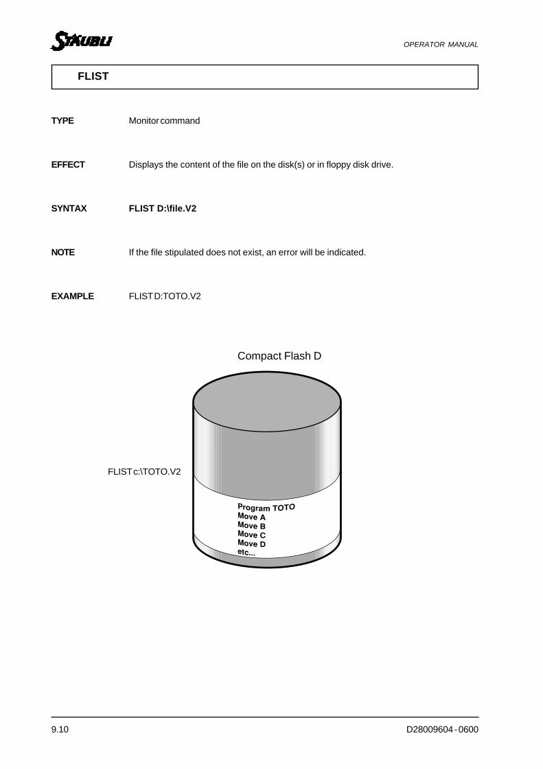
9.10 D28009604 - 0600
OPERATOR MANUAL
Disque Dur C
FLIST c: TOTO.PG
FLIST c:\TOTO.V2
FLIST
TYPE Monitor command
EFFECT Displays the content of the file on the disk(s) or in floppy disk drive.
SYNTAX FLIST D:\file.V2
NOTE If the file stipulated does not exist, an error will be indicated.
EXAMPLE FLIST D:TOTO.V2
Compact Flash D

D28009604 - 0600 9.11
OPERATOR MANUAL
FCOPY c: TOTO.V2 = c: TUTU.V2
Disque Dur C
FCOPY
TYPE Monitor command
EFFECT Copies an existing file onto a new file.
SYNTAX FCOPY file Target=Source file
EXAMPLE FCOPY D:NEWTOTO.V2=B:OLDTOTO.V2
NOTE Protected files cannot be copied.If the source file has a read only attribute, the target file will also have this attribute.
REMARK FCOPY does not accept the symbol *.V2 for example.
Compact Flash D
FCOPY D: TOTO.V2 = D: TUTU.V2

9.12 D28009604 - 0600
OPERATOR MANUAL
FDELETE c: TOTO.PG
Disque Dur C
FDELETE
TYPE Monitor command
EFFECT Deletes specified file.
SYNTAX FDELETE File.name
EXAMPLE FDELETE *.V2 will delete all files ending with the V2 extension.
Compact Flash D
FDELETE D:TOTO.V2

D28009604 - 0600 9.13
OPERATOR MANUAL
Disque Dur C
FRENAME
TYPE Monitor command
EFFECT Changes disk file name.
SYNTAX FRENAME D:New file name=Old file name
NOTE The system changes only the file name, the contents are not affected.
EXAMPLE FRENAME D:NEW.V2=OLD.V2
Compact Flash D

D28009604 - 0600 10.1
OPERATOR MANUAL
CHAPTER 10
CONTROL OF ROBOT CONFIGURATION

10.2 D28009604 - 0600
OPERATOR MANUAL
READY
READY
EFFECT Places robot arm in a specific reference position.
SYNTAX READY
NOTE Generally this specific position corresponds to the centre of all the axes.
This position may be slightly misaligned to each axis.
EXAMPLE .DO READY
In order to check the alignment of the marks on each axis, do READY with an RX_B (coordinates adjusted infactory after V_REGAUTO.

D28009604 - 0600 10.3
OPERATOR MANUAL
ALIGNWORLD Z
Z OUTIL
+X
+Z
WORLD
ALIGN
EFFECT Places the tool Z-axis parallel to the nearest axis of the world reference system (X or Y or Z).
SYNTAX ALIGN
NOTE This instruction avoids having to perform many handling operations using the teach pendantto set tool axes parallel with the Z-axis of the WORLD coordinates.
EXAMPLE . DO ALIGN
Z WORLD
Z TOOL
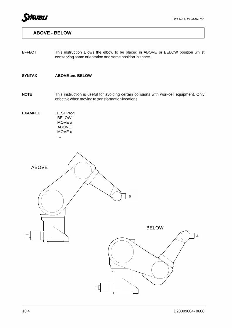
10.4 D28009604 - 0600
OPERATOR MANUAL
A
A
ABOVE
BELOW
ABOVE - BELOW
EFFECT This instruction allows the elbow to be placed in ABOVE or BELOW position whilstconserving same orientation and same position in space.
SYNTAX ABOVE and BELOW
NOTE This instruction is useful for avoiding certain collisions with workcell equipment. Onlyeffective when moving to transformation locations.
EXAMPLE .TEST Prog BELOW MOVE a ABOVE MOVE a ...
a
a

D28009604 - 0600 10.5
OPERATOR MANUAL
RIGHTY
LEFTY
RIGHTY-LEFTY
A
RIGHTY - LEFTY
RIGHTY - LEFTY
EFFECT Allows RIGHTY of LEFTY configuration to be set up while conserving same orientation andposition in space.
SYNTAX RIGHTY and LEFTY
NOTE This instruction is useful for avoiding certain collisions with workcell equipment. Onlyeffective when moving to transformation locations.
EXAMPLE LEFTYMOVE aRIGHTYMOVE a...
a

10.6 D28009604 - 0600
OPERATOR MANUAL
FLIP - NOFLIP
EFFECT Sets joint 5 configuration whilst conserving same y, p, r angles in WORLD referencesystem and same X, Y, Z position.
SYNTAX FLIP and NOFLIP
FLIP will give negative angle values at JT5NOFLIP will give positive angle values at JT5.
NOTE This instruction is useful for avoiding certain collisions with workcell equipment.
EXAMPLE FLIPMOVE aNOFLIPMOVE a
A
Z OUTIL
Z O
UT
IL
-
+
Z TOOL
Z TO
OL
a

D28009604 - 0600 A.1
OPERATOR MANUAL
APPENDIX

A.2 D28009604 - 0600
OPERATOR MANUAL
A.1. SAFETY NOTICE
The following notice is mandatory reading for all personnel involved with the operation, programming,maintenance or installation of the robot.
A robot, due to it's flexible, reprogrammable nature, represents a potential danger to personnel. It may not bepossible to predict with any accuracy it's motion at any point in time.
The duty falls therefore upon the personnel involved to ensure the following:- The area of operation of the robot is safeguarded by suitable physical barriers;- No personnel can approach the robot whilst it is under program control;- Reduced speed operations selected prior to personnel being in proximity with the robot arm;- Adequate training is given to personnel involved in any of the above activities;- Safe working practises are employed in all dealings with the robot;- Personnel involved with the robot are aware of guidelines which are provided and details of any local safe working
practises.
The following warnings should be complied with all dealings with the robot system.
DO NOT's:- DO NOT replace any components or make any adjustments to the equipment with any electrical or pneumatic
supply connected;- DO NOT attempt to move the robot arm until it has been securely mounted;- DO NOT block cooling fans when positioning the controller. Ensure that an unobstructed air flow is available;- DO NOT stop arm motion by using the emergency stop button except under emergency conditions;- DO NOT stop arm motion by using EMERGENCY STOP control except under exceptional circumstances. Arm
motion should be stopped by aborting program or selecting hold mode;- DO NOT stop arm motion by turning off cabinet mains control or isolator except under exceptional
circumstances. Arm motion should be stopped by aborting program or selecting hold mode;- DO NOT connect or disconnect any cables or pneumatic hoses unless all power has been removed from the
system;- DO NOT operate any equipment with the covers removed or doors open;- DO NOT approach the arm when it is operating under program controlled conditions;- DO NOT approach the arm when it is operating under teach conditions unless you personally have control of
the arm via the teach pendant.
DO's:- DO ensure that operating and maintenance personnel observe all safety precautions;- DO ensure that the robot working area is enclosed by a suitable physical barrier, which is suitably interlocked
with the robot control system such that entry forces an E-stop on the robot controller;- DO realise that when establishing the barrier position, consideration should be given to the working envelope
of the robot arm, including all payloads it may carry;- DO attempt to physically limit the working envelope of the robot arm to the minimum necessary to carry out
it's tasks;- DO ensure that all possible obstructions are removed from the robot's working area;- DO ensure that all personnel and obstructions are clear of the arm before applying ARM POWER;- DO ensure that whenever applying emergency stop a hand is kept near "Emergency stop" or DIS PWR buttons,
such that they can be easily operated should the need arise;- DO ensure that power is removed before connecting or disconnecting any electrical equipment;- DO ensure that the power is removed before opening any covers or attempting any mechanical or electrical
maintenance;

D28009604 - 0600 A.3
OPERATOR MANUAL
- Do follow the proper power up sequence when connecting components to line power;- DO start motions at lowspeed and only increase speed when paths are fully defined;
- DO realise that the automatic startup program will lead to the execution of a program and possible robot arm motion;- DO ensure that any tools and loads fitted to the robot meet the payload and inertial requirements of the arm;- DO realise that operations in excess of V+ speed 100 could cause over load of the motors and drive components
in the robot.
The manualsinvolved in any of the above activities; provided by Stäubli, both for the robot system and the V+programming language, are not intended as self-teaching guides. Personnel using them are expected to haveundertaken a period of training such as that proposed by Stäubli.
Failure to comply with these and over warnings may rsult in serious injury to personnel and/or damage to therobot system.

A.4 D28009604 - 0600
OPERATOR MANUAL
y = 100x = 30
z = 125
+X
+Y
+Z
+X+Y
+Z
A.2. TRANSFORMATION ELEMENTS
A.2.1. X, Y, Z, VALUES
In this example, X = 30, Y = 100, Z = 125, yaw = 0, pitch = 0 and roll = 0.
There is no orientation of the local (TOOL) coordinates with respect to the base (WORLD) Cartesian coordinates.
WORLD
TOOL
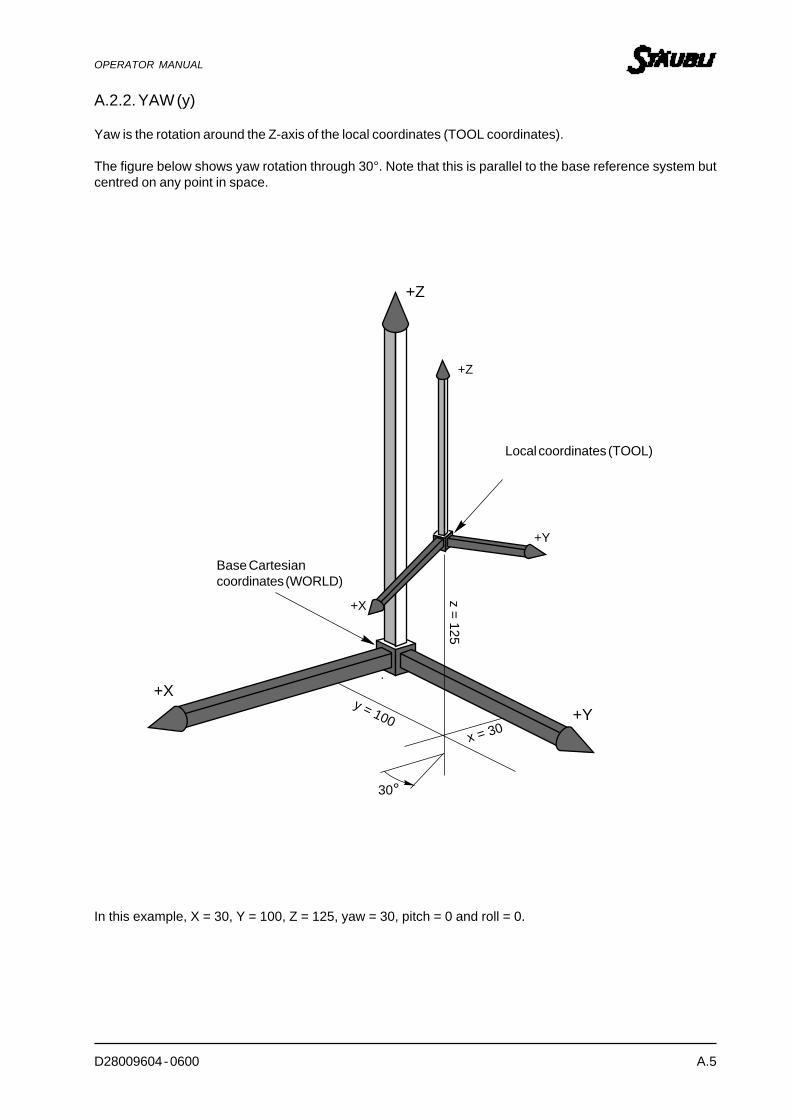
D28009604 - 0600 A.5
OPERATOR MANUAL
y = 100x = 30
z = 125
+X
+Y
+Z
+X
+Y
+Z
30°
A.2.2. YAW (y)
Yaw is the rotation around the Z-axis of the local coordinates (TOOL coordinates).
The figure below shows yaw rotation through 30°. Note that this is parallel to the base reference system butcentred on any point in space.
In this example, X = 30, Y = 100, Z = 125, yaw = 30, pitch = 0 and roll = 0.
Base Cartesiancoordinates (WORLD)
Local coordinates (TOOL)
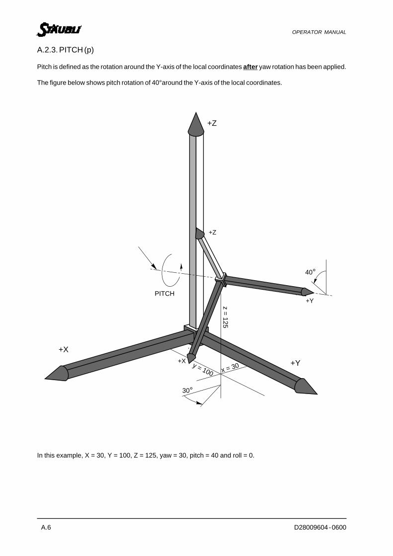
A.6 D28009604 - 0600
OPERATOR MANUAL
+Y
+X y = 100 x = 30
z = 125
+X
+Y
+Z
30°
40°
+Z
PITCH
A.2.3. PITCH (p)
Pitch is defined as the rotation around the Y-axis of the local coordinates after yaw rotation has been applied.
The figure below shows pitch rotation of 40°around the Y-axis of the local coordinates.
In this example, X = 30, Y = 100, Z = 125, yaw = 30, pitch = 40 and roll = 0.

D28009604 - 0600 A.7
OPERATOR MANUAL
+X
+Y
+Z+
: 125
20°
30°
+Z
+X
40°
ROLL
Z-axis of local coordinatesafter YAW and PITCH havebeen applied
A.2.4. ROLL (r)
Roll is defined as the rotation around the Z-axis of the local coordinates after YAW and PITCH rotations havebeen applied.
The figure below shows Roll rotation of 20° around the Z-axis of the local coordinates.
In this example, X = 30, Y = 100, Z = 125, yaw = 30, pitch = 40 and roll = 20.

A.8 D28009604 - 0600
OPERATOR MANUAL
A.3. LINE EDITOR
The advantage of this editor is that it is simple and compatible with the VAL 2 language editor.
This editor includes a certain number of commands.
NOTE These commands can be used only in editing mode («?» on LH side) to enter V+ instructions intothe robot.
These commands can be used to : - Modify a program.- Insert new instructions.- Delete instructions.- Search for certain instructions.- etc...
We shall now look at these editor instructions.
If you are in execution mode (*) or in command mode (.), go to editing mode by typing : EDIT

D28009604 - 0600 A.9
OPERATOR MANUAL
.
Commandmode
(.)
EDITORmode
(?)E
EDIT prog.name
(.) EDIT
EFFECT Places the robot in editor mode at specified line number.
SYNTAX EDIT prog.name, n
n: No. of line on which you wish to be positioned in a previously edited program.
EXAMPLE EDIT TOTO,7
NOTE Avoid EDITING a running program as serious incidents may occur.
REMARKS As this command is frequently used, it is preferable to use ED instead of EDIT.

A.10 D28009604 - 0600
OPERATOR MANUAL
Editor Mode Command Mode
(.)
Quit editorE
(?) E (EXIT)
EFFECT Quits editing mode and returns you to robot command mode, that is from (?) to (.).
SYNTAX E
NOTE This command is only active when robot is in editor mode.
EXAMPLE 1 ? MOVE a2 ? MOVE b3 ? E
Return to command mode...This command is used when you have finished writing or modifying a program.
REMARK You can exit from any program line.
1 ? MOVE a2 ? MOVE b3 ? E
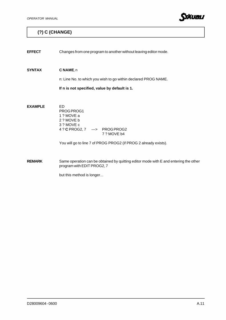
D28009604 - 0600 A.11
OPERATOR MANUAL
(?) C (CHANGE)
EFFECT Changes from one program to another without leaving editor mode.
SYNTAX C NAME, n
n: Line No. to which you wish to go within declared PROG NAME.
If n is not specified, value by default is 1.
EXAMPLE EDPROG PROG11 ? MOVE a2 ? MOVE b3 ? MOVE c4 ? C PROG2, 7 —> PROG PROG2
7 ? MOVE b4
You will go to line 7 of PROG PROG2 (if PROG 2 already exists).
REMARK Same operation can be obtained by quitting editor mode with E and entering the otherprogram with EDIT PROG2, 7
but this method is longer...

A.12 D28009604 - 0600
OPERATOR MANUAL
(?) D (DELETE)
EFFECT Deletes the specified number of lines.
SYNTAX D nn : number of lines.
NOTE If no value is specified for n, value by default is 1.
EXAMPLE ED TITI1 ? MOVE a2 ? MOVE b3 ? MOVE c4 ? MOVE d5 ? MOVE f6 ? MOVE g
If on line 2 ? MOVE byou type: 2 ? D 3you will delete line 2 and the 2 following lines.
Hence : 1 ? MOVE a2 ? MOVE f3 ? MOVE g
REMARK If you are 2 lines before the end of the program and you type D 21, deletion will not goback to start of program, it always stops at the end of the program.

D28009604 - 0600 A.13
OPERATOR MANUAL
(?) I (INSERT)
EFFECT Inserts one or more lines in a program.
SYNTAX I
NOTE To exit insertion mode, simply hit the -Return- key on a blank line.
EXAMPLE ED TOTO1 ? MOVE a To insert MOVE c1 and MOVE c2 between lines 3 and 42 ? MOVE b3 ? MOVE c4 ? MOVE d5 ? MOVE e
Therefore 4 ? MOVE d4 ? I4 ? MOVE c15 ? MOVE c25 ? (press -Return-)
Result ED TOTO1 ? MOVE a2 ? MOVE b3 ? MOVE c4 ? MOVE c15 ? MOVE c26 ? MOVE d7 ? MOVE e
Line numbers are automatically reassigned.

A.14 D28009604 - 0600
OPERATOR MANUAL
(?) L (LAST)
EFFECT Returns you to previous line.
SYNTAX L
NOTE To skip back several instructions, it is preferable to use the editor command S.
EXAMPLE ED TOTO1 ? MOVE a2 ? MOVE b3 ? MOVE c4 ? MOVE d4 ? L3 ? MOVE c
You can only move back one step at the time.
REMARK If you enter L when on program line No. 1, you will remain on line No. 1, but this isnonsensical.

D28009604 - 0600 A.15
OPERATOR MANUAL
(?) S (SEARCH)
EFFECT Searches for required line number.
SYNTAX S n where n: line No.
EXAMPLE 1 ED TOTO EXAMPLE 2 ED TOTO1 ? MOVE a 1 ? MOVE a2 ? MOVE b 2 ? MOVE b3 ? MOVE c 3 ? MOVE c4 ? MOVE d 4 ? MOVE d5 ? S 2 5 ? MOVE e2 ? MOVE b 6 ? S 20
20 ? MOVE k
Search backwards or Search forwards
REMARK If you specify a number which exceeds program line number, you will simply go to theend of the program.

A.16 D28009604 - 0600
OPERATOR MANUAL
(?) P (PRINT)
EFFECT Displays a certain number of lines on the screen.
SYNTAX P n where n: number of lines.
REMARK If P is given alone, only content of line where P command is located will be displayed.
NOTE Useful for displaying only a limited number of lines on screen.
EXAMPLE ED TOTO1 ? MOVE a1 ? P 31 ? MOVE a2 ? MOVE b3 ? MOVE c
REMARK If you are 2 lines off the end of the program and you enter P21, display will alwaysstop at end of program.
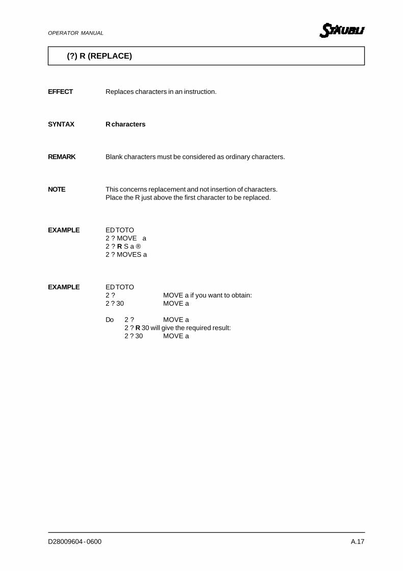
D28009604 - 0600 A.17
OPERATOR MANUAL
(?) R (REPLACE)
EFFECT Replaces characters in an instruction.
SYNTAX R characters
REMARK Blank characters must be considered as ordinary characters.
NOTE This concerns replacement and not insertion of characters.Place the R just above the first character to be replaced.
EXAMPLE ED TOTO2 ? MOVE a2 ? R S a ®2 ? MOVES a
EXAMPLE ED TOTO2 ? MOVE a if you want to obtain:2 ? 30 MOVE a
Do 2 ? MOVE a2 ? R 30 will give the required result:2 ? 30 MOVE a

A.18 D28009604 - 0600
OPERATOR MANUAL
(?) T (TEACH)
EFFECT Records the coordinates of a set of locations and automatically writes motion orderassociated with these locations (each time REC/DONE pushbutton located on teachpendant is pressed).Allows robot to be set to teach mode.
SYNTAX T point.name
NOTE This mode is useful when a succession of locations is to be recorded.
EXAMPLE ED TOTO1 Program TOTO ( )2 ? T d1When REC/DONE pushbutton is pressed, the following will be displayed:
2 MOVET d1,0 if grip closedorMOVET d1,1 if grip open.
If Record is pressed again, the following will be obtained :3 MOVET d2,0etc...
Each time REC/DONE is pressed, location index is automatically incremented.
REMARK A location recorded in TEACH mode can be modified later.

D28009604 - 0600 A.19
OPERATOR MANUAL
(?) TS (TEACH STRAIGHT)
EFFECT This command is same as T, except that motions will be straight line motions betweenrecorded locations.
SYNTAX TS variable name
NOTE This mode is useful when a succession of straight line locations is to be recorded.
EXAMPLE ED TOTO
1 Program TOTO ( )2 ? TS d1when REC/DONE pushbutton is pressed, the following will be displayed:
2 MOVEST d1, 0 if grip is closed or MOVEST d1, 1 if grip is open.
If REC/DONE is pressed again, the following will be obtained:3 MOVEST d2,0
etc.
Each time REC/DONE is pressed, location index is automatically incremented.
REMARK T and TS can be mixed within a program, but this is tedious.