rubber-cushioned wheels for light rail transit
TRANSCRIPT

Rubber-Cushioned Wheels for Light
Rail Transit
K. H. WEBER AND E. L. VAN SICKEL
F or decades rubber-cushioned wheels have proven very reli-able for light rail transit all
over the world. These wheels reduce shock and noise, and offer other bene-fits. With nearly 150,000 rubber-cushioned wheels in use, the following advantages can be demonstrated: less wear and tear of both permanent way and vehicle components, reduced dis-turbance from noise for both pas-sengers and people living along the track, and lower maintenance costs.
Traveling comfort and running quality of vehicles equipped with rubber-cushioned wheels are superior to vehi-cles equipped with rigid steel wheels. Recent tests using rubber-cushioned wheels on high-speed vehicles have also been successful. Today the rubber-cushioned wheel has been proven reliable for speeds up to 160 km/h (100 mph). Further tests are being planned for speeds up to 280 km/h (175 mph).
THE AVERAGE PERSON THINKING of a rail transit system thinks of rigid steel wheels. The uninformed are often surprised to find rubber in the midst of the steel wheel. That is because for all traditional rail traffic, with the exception of light rail transit, the wheel and rail are made of steel and are the essential load-bearing members. The steel wheel and the steel rail are always used when high load capacity and safe transportation are needed.
Over 50 years ago, however, Herschfeld in the United States invented the first commercially used rubber-cushioned--or resilient—wheel. He de-veloped this wheel so that he could build the light-weight car that became known as the President's Conference Committee (PCC) car. Prior to that time
Penn Machine Company, 905 Porter Building, Pittsburgh, Pa. 15219.

System Design and Vehicle Performance487
street rail vehicles had heavy trucks and heavy bodies to withstand the everyday pounding from special trackwork and rail joints. After Herschfeld perfected the rubber-cushioned wheel, he was able to lighten the truck and the carbody components to provide greater acceleration and deceleration. This improvement allowed the street rail vehicle to compete with the automobile in traffic. Since that time most light rail vehicles have been built using one type of rubber-cushioned wheel or another.
USE OF RUBBER SPRING MATERIAL
Rubber will not take high-tensile loads. Therefore, springs made of. rubber should be arranged so that they are not subject to tensile loads, or the rubber will be destroyed after a very short time. On the other hand, rubber is suited to take high-compression and shear loads. In the majority of the wheel designs that have been proposed in very large numbers and varieties, the rubber is usually subjected to a combination of compression and shear loads. Under compression loads the rubber body must not be totally enclosed because in this condition the rubber reacts like a liquid. That is, the rubber is fully inelastic and rigid and offers no spring travel.
The size of the rubber bodies should be such that under operating condi-tions the rubber is deformed over its total cross-section. If parts of the cross-section are not properly squeezed, the rubber is subject to premature aging that gradually leads to its destruction.
If rubber is subjected to shear loads, the largest possible deflection must not result in any lengthening of the rubber. That is, additional tensile loads must not occur. Therefore, rubber bodies subjected to shear loads should always be prestressed with compression.
Under compression loads the deflections are small. Under shear loads larger deflections can be obtained. On the other hand, under compression loads the required rubber volume can be less as compared with shear loads since higher load is permitted.
Premature aging of the rubber also occurs if it is subjected to higher temperatures than acceptable. Different grades of rubber can be used that vary only in their capability to resist heat (110°C being the maximum). Apart from the formation of heat from the normal operation of the rubber wheel in service, heat is also put into the wheel from outside of the rolling operations and should be taken into consideration. This outside heat souive can be from tread braking or reprofiling of the tread by means of grinding. The heat input from tread braking is generally well above the acceptable temperature that the rubber can take. Therefore, the rubber-cushioned wheel cannot be recom-mended for vehicles using tread brakes as the main service brake.

488 Lici-rr RAn.. TRANSIr NEW SYSTEM SUCCESSES
ADVANTAGES OF RUBBER-CUSHIONED WHEELS
Rubber-cushioned wheels were designed to reduce the unsprung masses in the wheelset resulting in the reduction of shock forces between the wheel and the rail, and to reduce the noise of operation.
In the general design of rail vehicles, the primary suspension is situated between the axle boxes and the truck frame. This suspension not only improves the traveling comfort of passengers but also reduces the shock forces because of its resilience. With traditional rigid wheelsets the wheels, axles, and other components mounted to the axle, such as gears, brake discs, roller bearings, and journal boxes, form what is called the unsprung mass. In driving wheelsets part of the mass of the motor may also be supported by the axle, which thus increases the total unsprung mass.
With rigid steel wheels the complete wheelset, with all these components, is bouncing and hammering on the track. With high traveling speeds, high dynamic forces both in vertical and lateral directions are occurring between the wheel and rail, leading to fatigue and wear of material. By lowering the unsprung mass of the wheelset the impact of the dynamic forces is consider-ably reduced. With the cushioning member built into the wheels the unsprung mass is limited to the two-wheel tires. Figure 1 illustrates the unsprung masses of the wheelset with rigid wheels compared with a wheelset with rubber-cushioned wheels.
The reduction of noise is also one of the advantages of rubber-cushioned wheels. With the reduction of the shock forces between the wheel and the rail as explained above, the rolling noises from traction are reduced. The largest amount of noise reduction for the passengers comes from the fact that the ground vibration is damped on its way from the source, the wheel/rail contact surface, to the bogies and the carbody. Also, the curve squeal is changed to a lower, less disturbing frequency.
Another advantage of the rubber-cushioned wheel is that it reduces shock forces tangent to the wheel tread caused by sudden acceleration and decelera-tion. This results in longer gear life.
MAJOR DESIGNS OF RUBBER-CUSHIONED WHEELS
First design proposals were made and patents taken out for rubber-cushioned wheels as early as 1880. First designs, however, did not go beyond the stage of testing, probably because of lack of knowledge of the characteristics of rubber.

System Design and Vehicle Performance 489
FIGURE 1 Unsprung mass of a wheelset.
Figure 2 shows basic sketches of the major designs of rubber-cushioned wheels. Next to each sketch there is information as to the direction in which the built-in rubber body is loaded (radial, axial, and tangential direction).
With certain reservations, the respective spring characteristic of each wheel can be determined from the way that the rubber is loaded. The wheel shown at the top of Figure 2 will show less deflection in the radial direction because the rubber is predominantly compression loaded. However, the wheel should show a larger deflection in axial and tangential directions as there is shear load in those directions. In contrast to the top wheel, a wheel designed like the bottom one in Figure 2 should give higher deflection in the radial and tangential directions than in the axial direction, where it would be loaded in compression.
The middle wheel shown in Figure 2 has a soft spring characteristic in the tangential direction. By changing the angle of inclination of the rubber body, the combination of compression and shear loads can be arranged to allow for a wide range of deflection in both the radial and axial directions.

490 LIGHT RAIL Tiwisrr. NEW SYSTEM SUCCESSES
Kind of Stressing
radial predorninent pressure
axial shear
tangential shear
radial
axial pressure . shear
tangential shear
radial shear
axial pressure
- tangential shear
FIGURE 2 Types of rubber-cushioned wheels.
DESIGN CRITERIA
A rubber-cushioned wheel for rail vehicles should be of simple design, economical, reliable, and offer the previously mentioned advantages, such as reduction of vertical and lateral shock forces; reduction of rolling, squealing, and internal noises; and reduction of wheel tire wear. These requirements are met ideally by the wheel of the design Bochum 54, illustrated in Figure 3. This is a design that, for more than 30 years, has proved successful in light rail transit up to a wheel load of 6 metric tons.
By this time, nearly 150,000 wheels of this design have been put in use by transit authorities all over the world, including the United States. The simple design consists of three elements: the wheel tire, the rubber elements, and the wheel center. In line with the best practice for the use of rubber as a spring element, the rubber bodies are built in between the wheel tire and the wheel center and are prestressed by high radial pressure. This ensures that in the critical axial and tangential directions most of the deformation of the rubber takes place as shear loads.
Assembly of the wheel is accomplished easily by a special pressing-in device (see Figure 4). The wheel center is pressed into the rubber-lined bore of the wheel tire by means of a cone. The rubber blocks are designed so that a static radial deflection of 0.5 to 0.7 mm and an axial deflection of approx-imately 2 mm are obtained under service conditions. The spring rate in
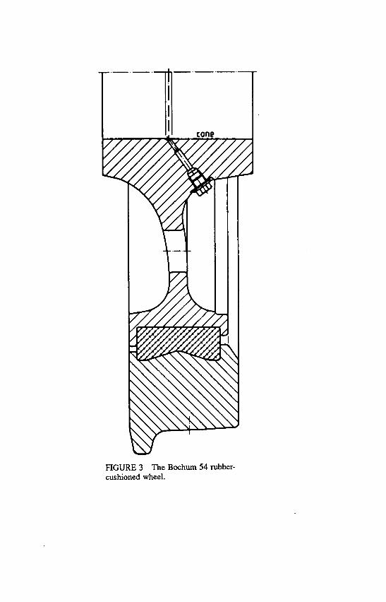
HGURE 3 The Bochum 54 rubber-cushioned wheel.

492 LIGHT RAil. TlNsrr NEw SYSTEM SUCCESSES
FIGURE 4 Assembly of the Bochum 54.
transverse, tangential, and radial directions has been adapted for various types of vehicles by changing the size of the rubber blocks to obtain optimum spring characteristics for each application.
The wheel illustrated in Figure 5 has been developed based on the same principles of design as the Bochum 54 wheel. This wheel is marketed under the name Bochum 84 and consists of four construction members: the wheel tire, the rubber blocks, the wheel center, and the detachable ring (see Figure 6). The detachable ring is fitted to the wheel center by a cOnical pressfit. In addition to the pressfit, the detachable ring is secured to the wheel center with bolts, although the pressfit alone is enough to hold the ring in proper position under load conditions occurring in service.
For easy disassembly the detachable ring is provided with an oil injection hole so that oil pressure can assist in taking off the ring. Assembly and disassembly of the rubber-cushioned wheel design Bochum 84 can be accom-plished easily with hand tools. In the case of wheelsets with inner roller bearings, the wheel can be equipped with new tires with the axles still under the vehicle.

System Design and Vehicle Performance 493
Wheels of this new Bochum 84 design are now being used under the new light rail vehicles in Grenoble, France, and have been ordered for light rail vehicles in Lausanne, Switzerland. Under service conditions, similar perfor-mance can be expected from both wheel designs as they are manufactured to more or less identical spring characteristics. The two wheels are equal with regard to reduction of shock and noise.
FIELD TESTS OF BOCHUM 54 AND 84 WHEELS
To prove that rubber-cushioned wheels have the advantages claimed, tests have been carried out with a number of transit authorities to measure reduc-tion of both shock and noise compared to vehicles equipped with conven-tional rigid steel wheels. We will discuss here some tests run with transit authorities in Hamburg (Hamburger Hochbahn AG) (1) and Vienna (Wiener Verkehrsbetriebe), among others.
Reduction of Shock
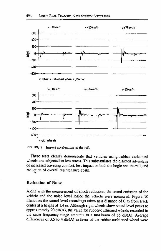
A steel plate 2 mm high was welded on the rail head to simulate a badly maintained rail joint or a frog point on a turnout. The test vehicles passed over this steel plate at speeds of 30 km/h, 50 km/h, and 75 km/h. The test results summarized in Figure 7 clearly show the advantage offered by the rubber-cushioned wheel. With the rubber-cushioned wheel, the peak values of the shock forces are lower by approximately 30 to 40 percent at 75 km/h.
The effect that speed has on the shock forces is illustrated in Figure 8. This diagram illustrates the accelerations at the rail, at the journal box, and at the bogie or truck frame.
Measurements of the bending stresses occurring in the main beam of the truck frame made in the Hamburg tests show that the pulsating bending stresses are reduced by an average of 16 percent for vehicles equipped with rubber-cushioned wheels as compared with vehicles with rigid wheels. Ac-cording to test data, engineers can take into consideration for stress calcula-tions a reduction of 50 percent of the acceleration peaks for lateral and vertical loads when using rubber-cushioned wheels.
Figure 9 illustrates the acceleration peaks determined for the stress calcula-tion of the construction members used on wheelsets with rigid wheels and

FIGURE 5 The Bochum 84 rubber-cushioned wheel.

System Design and Vehicle Performance 495
FIGURE 6 The Bochum 84 wheel.
rubber-cushioned wheels, respectively. These values have been established for a new guideline for calculations issued by the German Association of Public Transit Authorities (V0V) (2). In the design of wheelsets, dynamic loads must be added to the static loads that the wheelset must carry. These dynamic loads can be reduced by 25 percent in the lateral direction and 37.5 to 50 percent in the vertical direction when rubber-cushioned wheels instead of rigid wheels are used.
Similar reductions of dynamic forces have been taken into consideration in the stress calculations for axles. Therefore, in the design of axles for wheel-sets with rubber-cushioned wheels the dimensions can be reduced. Con-versely, tests have shown that such axles with smaller dimensions designed for the use of rubber-cushioned wheels have actually cracked after a few million load cycles when used with rigid wheels.
yr 30km/h
496 Lici-rr R.krL. T1t.ANsrr NEW SYSTEM SUCCESSES
v50kmfh v75km/h
rubber cushioned wheels ,,Bo 54•
v: 30km/h v50km/h v:lSkm/h
rigid wheels
FIGURE 7 Impact acceleration at the rail.
These tests clearly demonstrate that vehicles using rubber cushioned wheels are subjected to less stress. This substantiates the claimed advantage of increased traveling comfort, less impact on both the bogie and the rail, and reduction of overall maintenance costs.
Reduction of Noise
Along with the measurement of shock reduction, the sound emission of the vehicle and the noise level inside the vehicle were measured. Figure 10 illustrates the sound level recordings taken at a distance of 6 m from track center at a height of 1.4 m. Although rigid wheels show sound level peaks to approximately 90 dB(A), the value for rubber-cushioned wheels recorded in the same frequency range amounts to a maximum of 85 dB(A). Average differences of 3.5 to 4 dB(A) in favor of the rubber-cushioned wheel were

acceleration at the roil
/<A
-200 0 •-•
50 75 vlkmlhi
acceleration at axle box
80- 0
60- 01--<
30 50 75 vtkin/b
acceleration at the bogie fume
2Z3 o---O
A_._. -A
AS(3P 8o54 0 SGP, rigid wheel (damped)
50 75 v (km/hi
FIGURE 8 Impact acceleration at rail, axle box, and bogie frame.

498 Licwr RAIL Tiw.jsrn NEw SYsTEM SuccEssEs
main level direction direction of yield point fatigue of oscillation oscillaben
with vertical 20-30 15-20 rubber cushioned horizontal wheels transverse 4-5 3-4
vertical 30-40 20-20 with
horizontal rigid wheels
transverse 6-8 5-6
FIGURE 9 Acceleration amplitudes (m/s2) as proof of strength.
rigid wheels (damped)
FIGURE 10 Noise level.
rubber cushioned wheels
measured. Inside the car the sound level transmitted by air is lower by 3 dB(A), with the noise coming in a lower frequency range that is less disturbing to the passengers. All of these results were based on tests on tangent track with continuous welded rail plus ballast and tie construction. They represent measurements of the mlling noise.
Curve squeal of rigid wheels is generally eliminated with a rubber-cushioned wheel. Under some adverse conditions squealing might still be heard, but because of the good damping characteristics of the rubber blocks the noise level is reduced by approximately 8 to 10 dB(A) compared with rigid wheels. This reduction of noise by rubber-cushioned wheels not only benefits the peeple riding in the vehicle but also is much less disturbing to the people living along the track.

System Design and Vehicle Performance 499
Reduction of Wear
For light rail vehicles the life of a wheel is determined by the wear of the flange rather than by the wear of the tread. This is because most light rail vehicles travel around fairly sharp radius curves in comparison to main line or heavy rail transit. When the flange is worn to its limit, tread and flange contours require recontouring. To reproduce the original size of the flange, it is necessary to machine off good material from the tread during the machin-ing operation. With the use of rubber cushioned wheels, either Bochum 54 or Bochum 84, wear at the tread, and particularly at the flange, is reduced. The reduction of the peak loads in both the vertical and lateral directions, as mentioned above, leads to less wear on the tread. In addition, flange wear is reduced by the spring characteristics in the axial direction. This allows the shock forces resulting when the flange hits the rail, particularly when nego-. dating curves, to be absorbed elastically. Also, the forces on the flange cause the tire to rotate about a vertical axis, thus smoothing the angle of attack of the wheel towards the edge of the rail. Wear is proportional to the product of force and angle of attack. Thus the wearing components are changed to smaller values, which results in reduced wear.
Experience by many users shows that rubber-cushioned wheels increase the mileage as compared with rigid wheels by between 25 and 40 percent. This obviously is an economic advantage because of longer periods between reconditioning operations, reduced down time for vehicles, and reduced general maintenance costs.
Maintenance
Experience with a number of users has shown that a mileage life of 350,000 to 600,000 km is quite common with rubber-cushioned wheels with axle loads of 9 to 12 metric tons. Under favorable operating conditions a mileage life of 1.1 million km has been reached.
The rubber-cushioned wheels do not require the user to observe special maintenance instructions. Reconditioning of the tread and flange profile can be done on standard underfloor grinding machines or turning lathes in the same way that it is done for rigid wheels. The only precaution needed is that, when the tread by is reprofiled by grinding, care should be taken that the temperature of the surface of the bore of the tire is kept within acceptable limits so the rubber will not age prematurely. If a user is going to reprofile wheels by grinding, rubber material that is able to take temperatures of 100°C without risk of Josing its damping and spring characteristics should be used.
Re-tiring of the rubber-cushioned wheel is done at room temperature on a specially designed pressing-in device, either with a single wheel or with a

500 Licwr R.n. TRAiJsrn NEW SYsTEM SUCCESSES
complete wheelset. Re-tiring on a loose wheel is particularly advantageous for wheels that have been equipped with oil pressure-assisted conical pressfits to the axle. The conical pressfit with a taper of 1:150 or 1:300 has proven itself in service in Europe for over 15 years. There have been no pmblems with regard to proper seating of the wheel on the axle. This practice should be considered in America. As the wheels do not require any special shrink fit or press-on fit tolerance, the wheels can be stored in finished machined condi-don for use at random, thus speeding up the rewheeling operation.
FIGURE 11 Bochum 84 wheel for high speeds.

System Design and Vehicle Performance 501
FIGURE 12 Light-weign rubber-cushioned wheel.
The natural useful life of the rubber blocks is approximately 10 to 12 years. Normally the rubber blocks are replaced during the re-tiring operation. If the rubber blocks have not been subjected to excessive peak loads during service, they may be reused for another cycle of operation. However, rubber blocks with built-in shunts should be replaced during each re-tiring operation. The contact surface between shunt and wheel center and wheel tire, respectively, must be coated properly with an anticorrosive, but conductive, agent such as zinc paint to ensure low resistance to the current.
The Bochum 84 wheel does not need a special pressing-in device. This wheel design is assembled easily using only hand tools.
If the vehicle is parked for a long period, the rubber blocks will take a certain "set." That is, the wheel tire will be eccentric in relation to the wheel

502 LIGHT RAIl. TiNsrc NEW SYSTEM SUCCESSES
center. This is not a problem because after a few turns of the wheel the true running characteristics of the wheel are quickly reestablished.
PROSPECTS FOR RUBBER-CUSHIONED WHEELS
Bochum 54 and Bochum 84 wheels are presently adapted for use under high speeds (see Figure 11). As of today, the rubber-cushioned wheel has proved reliable in service up to a speed of 160 km/h (100 mph). In early 1989, the wheels will be tested under vehicles of the German Federal Railways at speeds up to 280 km/h (175 mph).
In addition to this development, steps have been taken to further reduce the weight of the wheel. The design of a wheel center with a tangentially corrugated web is one step in this direction. This design offers a reduction of weight by approximately 30 to 35 kg for a wheel having 900 mm diameter tread (see Figure 12).
REFERENCES
E. Raquet. Ermittlung der dynamischen Beanspruchung von Schiene und Farhzeug beim Einsatz starrer und gefederter Racier. Messtechnische Briefe MTB 11, Vol. 3, 1975. H. Burgarcic. Die Vorlaufige Fassung der Empfehlungen für die Festigkeits-auslegung von Personenfahrzeugen nach BOStrab. ZEV-Glasers Annalen Nr. 111, Vol. 8, 1987.