rt15 berkeley | real-time simulation of a modular multilevel converter based hybrid energy storage...
TRANSCRIPT
Real-Time Simulation of A Modular Multilevel
Converter Based Hybrid Energy Storage System
Feng Guo, PhDNEC Laboratories America, Inc.
Cupertino, CA
5/13/2015

2
Outline
• Introduction
• Proposed MMC for Hybrid Energy Storage System
• Real-Time Simulation Results
• Conclusions

Research TargetDesign and Management
Technologies that enable the development of robust multi-
carrier energy hubs ( akamicro-grids) addressing the
triple bottom line of reliability, economy, and environment.
• Power/Energy Systems – Dynamics and Operation, Power electronics.
• Optimization – Linear and non-linear techniques, Stochastic and Dynamic programming, Robust optimization.
• Economics – economic dispatch, energy markets.
ExpertiseExpertise
Reliability
EnvironmentEconomy
Energy Management Department
3
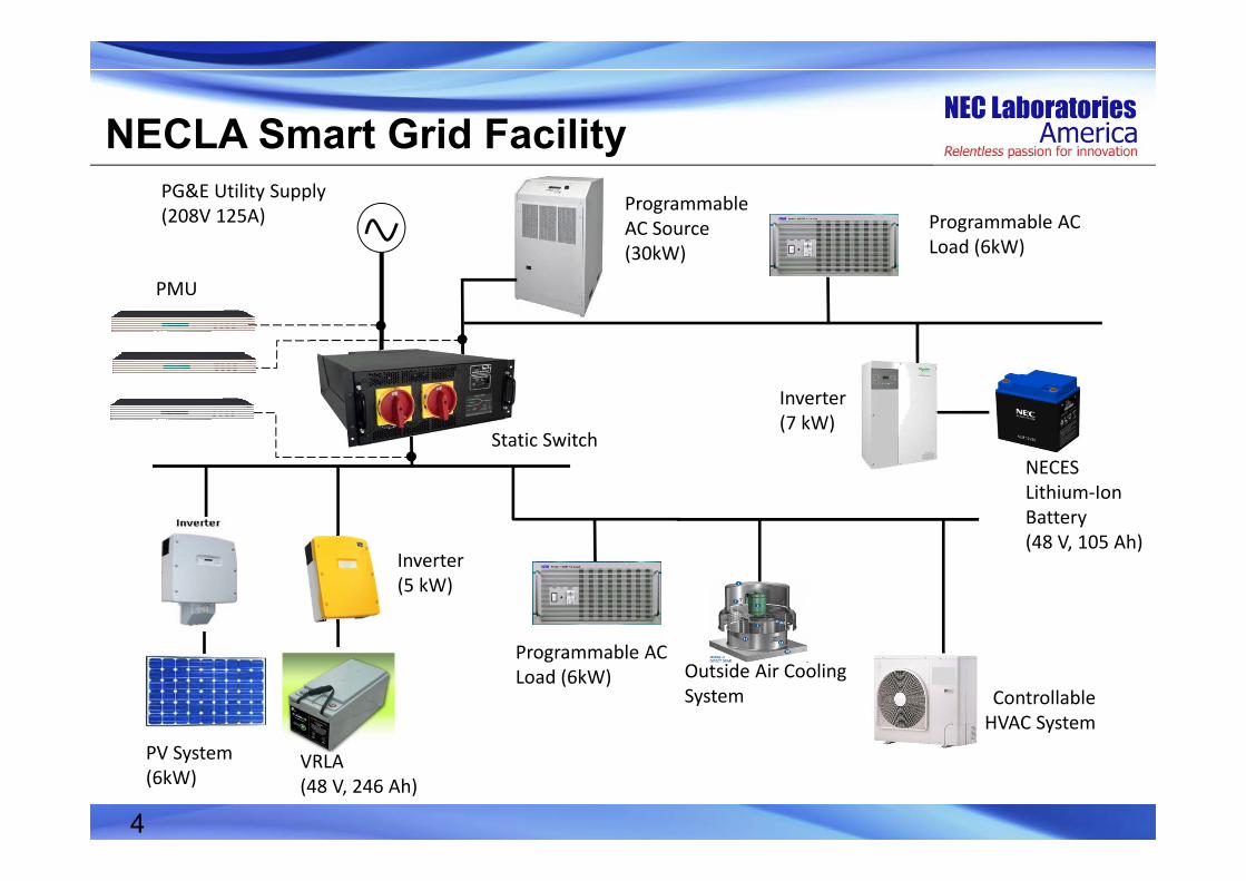
Outside Air Cooling System
PG&E Utility Supply (208V 125A)
ControllableHVAC System
NECLA Smart Grid Facility
Static Switch
Programmable AC Source(30kW)
Programmable AC Load (6kW)
NECES Lithium‐Ion Battery (48 V, 105 Ah)
PV System(6kW)
Programmable AC Load (6kW)
VRLA(48 V, 246 Ah)
Inverter (7 kW)
Inverter (5 kW)
PMU
4
5
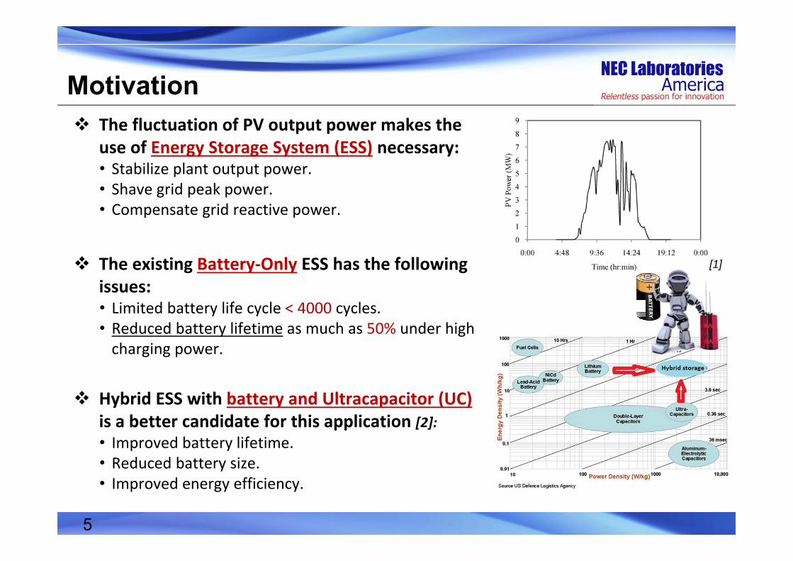
Motivation The fluctuation of PV output power makes the
use of Energy Storage System (ESS) necessary:• Stabilize plant output power.• Shave grid peak power.• Compensate grid reactive power.
The existing Battery‐Only ESS has the following issues:• Limited battery life cycle < 4000 cycles.• Reduced battery lifetime as much as 50% under high charging power.
Hybrid ESS with battery and Ultracapacitor (UC) is a better candidate for this application [2]:• Improved battery lifetime.• Reduced battery size.• Improved energy efficiency.
[1]

Battery UltraCap
Utility Grid
Existing Circuit Topologies However, current Power Conversion System (PCS) of the HESS has the
following issues:• Extra dc/dc converters are needed.• Not suitable for high power systems (>100 kW).• Lower reliability.
Battery
UltraCap
Utility Grid
Utility Grid
Battery
UltraCap
One dc/ac inverter [3] One dc/dc converter and one dc/ac inverter [4]
Two dc/dc converters and one dc/ac inverter [5]
6

Proposed MMC Based HESS
SubModule Two switches One UC
Arm N SMs in series One inductor
MMC Six identical arms One battery
UCSwitch
SM 1
Inductor
SM 2
SM n
BatteryA B C
Equivalent SMs
Inductor
7

Operation Principle
Compared to a typical MMC case, the proposed MMC has different operation principles: 1) The average active power of each SM is not necessarily equal to zero, and the power
from the dc side is not necessarily equal to the ac side.2) The sum of UC voltages in one arm will not necessarily be equal to the battery
voltage at dc bus.
8
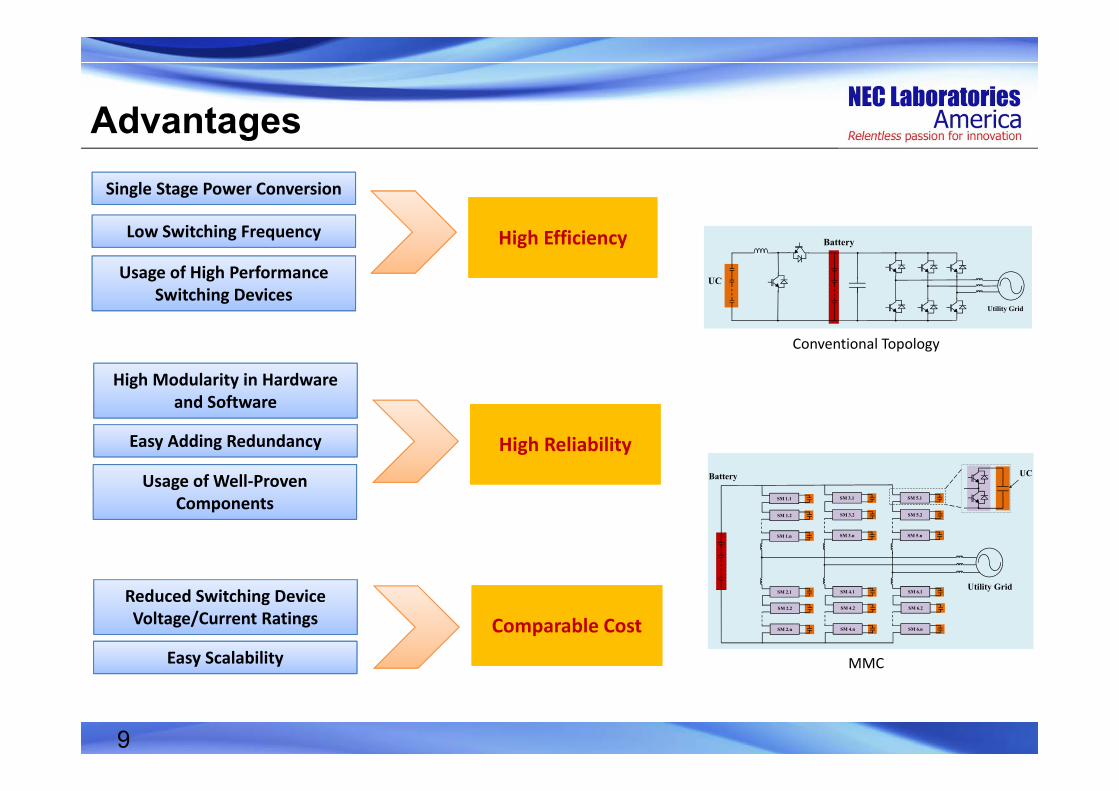
AdvantagesSingle Stage Power Conversion
Low Switching Frequency High EfficiencyHigh Efficiency
Reduced Switching Device Voltage/Current Ratings Comparable CostComparable Cost
Easy Scalability
Easy Adding Redundancy High ReliabilityHigh Reliability
High Modularity in Hardware and Software
MMC
Conventional Topology
Usage of Well‐Proven Components
Usage of High Performance Switching Devices
SM 5.n
SM 5.1
Utility Grid
Battery
SM 6.1
SM 6.n
SM 4.1
SM 4.n
SM 2.1
SM 2.n
SM 3.n
SM 3.1
SM 1.n
SM 1.1
SM 5.2 SM 3.2 SM 1.2
SM 6.2 SM 4.2 SM 2.2
UC
Battery
UC
Utility Grid
9
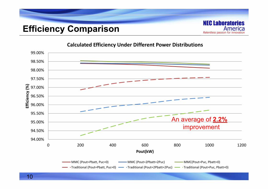
Efficiency Comparison
94.00%
94.50%
95.00%
95.50%
96.00%
96.50%
97.00%
97.50%
98.00%
98.50%
99.00%
0 200 400 600 800 1000 1200
Efficiency (%
)
Pout(kW)
Calculated Efficiency Under Different Power Distributions
MMC (Pout=Pbatt, Puc=0) MMC (Pout=2Pbatt=2Puc) MMC(Pout=Puc, Pbatt=0)Traditional (Pout=Pbatt, Puc=0) Traditional (Pout=2Pbatt=2Puc) Traditional (Pout=Puc, Pbatt=0)
An average of 2.2%improvement
10
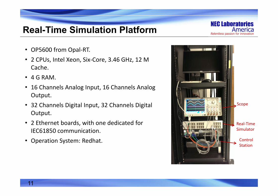
Real-Time Simulation Platform
Real‐Time Simulator
Scope
Control Station
• OP5600 from Opal‐RT.• 2 CPUs, Intel Xeon, Six‐Core, 3.46 GHz, 12 M Cache.
• 4 G RAM.• 16 Channels Analog Input, 16 Channels Analog Output.
• 32 Channels Digital Input, 32 Channels Digital Output.
• 2 Ethernet boards, with one dedicated for IEC61850 communication.
• Operation System: Redhat.
11

Circuit Topology Simulation• CPU based simulation.• One core can handle the entire model.• Simulation time step: 20 us.
Number of submodules per arm, N 4Battery voltage, VBatt 1 kVRated power, Pout 1 MWGrid voltage, Vgrid 480 VrmsFundamental frequency, f 60 HzSwitching frequency, fs 1.25 kHzCapacitance of the UC, C 2.5 FResistance of the buffer inductor, Rc 2 mΩInductance of the buffer inductor, Lc 500 uHLine resistance, Rf 1 mΩLine inductance, Lf 120 uH
SM 5.n
SM 5.1
Utility Grid
Battery
SM 6.1
SM 6.n
SM 4.1
SM 4.n
SM 2.1
SM 2.n
SM 3.n
SM 3.1
SM 1.n
SM 1.1
SM 5.2 SM 3.2 SM 1.2
SM 6.2 SM 4.2 SM 2.2
UCVC11
12
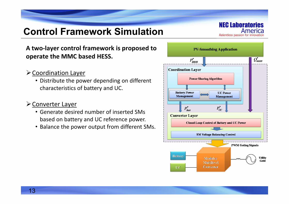
Control Framework SimulationA two‐layer control framework is proposed to operate the MMC based HESS.
Coordination Layer• Distribute the power depending on different characteristics of battery and UC.
Converter Layer• Generate desired number of inserted SMs based on battery and UC reference power.
• Balance the power output from different SMs.
13

Real-Time Simulation Results• The power from the battery and UC can be controlled independently from each other.
• The multilevel AC output voltage can be seen clearly.
14

Real-Time Simulation Results (Cont’d)• The HESS helps to smooth the PV output power.• The real‐time simulation helps us obtain the circuit operation detail, at the same time reach a long period of time.
15

Conclusions
In this presentation, a Modular Multilevel Converter based Battery‐UltraCapacitor Hybrid Energy Storage System is proposed for Photovoltaic applications.
Compared to the traditional HESS topologies, the proposed system features high efficiency, high reliability, and comparable cost.
A two‐layer control framework is proposed to operate the MMC based HESS.
Real‐time simulation results validate the effectiveness of the proposed control framework.
16

References[1] A. Omran, M. Kazerani, and M.M.A. Salama, “Investigation of methods for reduction of power fluctuations
generated from large grid-connected Photovoltaic systems,” IEEE Trans. Energy Conversion, vol. 26, no. 1, pp. 318-327, Mar. 2011.
[2] Y. Ye, P. Garg, and R. Sharma, “An Integrated Power Management Strategy of Hybrid Energy Storage for Renewable Application,” Proceedings of IECON 2014 -- The 40th Annual Conference of the IEEE Industrial Electronics Society, 2014, pp. 3088-3093.
[3] R. Dougal, S. Liu, and R. White, “Power and life extension of battery-ultracapacitor hybrids,” IEEE Trans. Components and Packaging Technologies, vol. 25, no. 1, pp. 120-131, Mar. 2002.
[4] L. Gao, R. Dougal, and S. Liu, “Power enhancement of an actively controlled battery/ultracapacitor hybrid,” IEEE Trans. Power Electronics, vol. 20, no. 1, pp. 236-243, Jan. 2005.
[5] B. Hredzak, V. Agelidis, and G. Demetriades, “A Low Complexity Control System for a Hybrid DC Power Source Based on Ultracapacitor–Lead–Acid Battery Configuration,” IEEE Trans. Power Electronics, vol. 29, no. 6, June 2014.