rt120 - ditch witch · the rt120 is a riding trencher designed to install buried service lines of...
TRANSCRIPT

RT120
Operator’s Manual
Issue 1.0Original Translation
CMW® 053-2697

RT120 Operator’s Manual Overview - 1
CMW
Overview
Chapter Contents
Serial Number Location . . . . . . . . . . . . . . . . . . . . . . 2
Intended Use . . . . . . . . . . . . . . . . . . . . . . . . . . . . . . . 3
Equipment Modification . . . . . . . . . . . . . . . . . . . . . . 3
Unit Components . . . . . . . . . . . . . . . . . . . . . . . . . . . 4
Operator Orientation. . . . . . . . . . . . . . . . . . . . . . . . . 5
About This Manual . . . . . . . . . . . . . . . . . . . . . . . . . . 5
• Bulleted Lists. . . . . . . . . . . . . . . . . . . . . . . . . . . . . . . . . . . . . . . . . . . . . . 5
• Numbered Lists . . . . . . . . . . . . . . . . . . . . . . . . . . . . . . . . . . . . . . . . . . . . 5

Overview - 2 RT120 Operator’s ManualSerial Number Location
CMW
Serial Number LocationRecord serial numbers and date of purchase in spaces provided. RT120 (1) and engine serial numbers (2) are located as shown.
Date of manufacture
Date of purchase
RT120 serial number
Front attachment serial number
Rear attachment serial number
Trailer serial number
Engine serial number
t41om001w.eps
1 2

RT120 Operator’s Manual Overview - 3Intended Use
CMW
Intended UseThe RT120 is a riding trencher designed to install buried service lines of various sizes using a variety of Ditch Witch attachments.
This unit is designed for operation in temperatures typically experienced in earth moving and construction work environments. Provisions may be required to operate in extreme temperatures. Contact your Ditch Witch dealer. Use in any other way is considered contrary to the intended use.
The RT120 should be used with genuine Ditch Witch chain, teeth, and sprockets. It should be operated, serviced, and repaired only by persons familiar with their particular characteristics and acquainted with the relevant safety procedures.
Equipment ModificationThis equipment was designed and built in accordance with applicable standards and regulations. Modification of equipment could mean that it will no longer meet regulations and may not function properly or in accordance with the operating instructions. Modification of equipment should only be made by competent personnel possessing knowledge of applicable standards, regulations, equipment design functionality/requirements and any required specialized testing.
The protection offered by the Rollover Protective System (ROPS) will be impaired if it has been subjected to any modification, structural damage, or has been involved in an overturn accident. The ROPS must be replaced after a roll-over.
Attachment Max. width/diameter Max. depth*
H910 trencher 24” (610 mm) 100” (2.5 m)
H911 trencher 24” (610 mm) 96” (2.4 m)
H932 plow 3” (80 mm) 36” (915 mm)
H952 combo
trencher 12” (305 mm) 70” (1.8 m)
plow 3” (76 mm) 36” (915 mm)
H1140 saw 6” (150 mm) 40” (1000 mm)
RC120 reel carrier
A920 backhoe 24” (610 mm) 109” (2.4 m)
Overview - 4 RT120 Operator’s ManualUnit Components
CMW
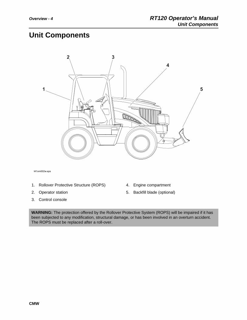
Unit Components
1. Rollover Protective Structure (ROPS)
2. Operator station
3. Control console
4. Engine compartment
5. Backfill blade (optional)
WARNING: The protection offered by the Rollover Protective System (ROPS) will be impaired if it has been subjected to any modification, structural damage, or has been involved in an overturn accident. The ROPS must be replaced after a roll-over.
t41om002w.eps
1
2 34
5

RT120 Operator’s Manual Overview - 5Operator Orientation
CMW
Operator Orientation
Right and left sides of machine are determined by facing front of unit while seated at the controls.
About This ManualThis manual contains information for the proper use of this machine. See Operation Overview for basic operating procedures. Cross references such as “See page 50” will direct you to detailed procedures.
Bulleted Lists
Bulleted lists provide helpful or important information or contain procedures that do not have to be performed in a specific order.
Numbered Lists
Numbered lists contain illustration callouts or list steps that must be performed in order.
1. Front of unit
2. Right of unit
3. Rear of unit
4. Left of unit

Overview - 6 RT120 Operator’s ManualAbout This Manual
CMW
RT120 Operator’s Manual Foreword - 7
CMW
Foreword
This manual is an important part of your equipment. It provides safety information and operation instructions to help you use and maintain your Ditch Witch equipment.
Read this manual before using your equipment. Keep it with the equipment at all times for future reference. If you sell your equipment, be sure to give this manual to the new owner.
If you need a replacement copy, contact your Ditch Witch dealer. If you need assistance in locating a dealer, visit our website at www.ditchwitch.com or write to the following address:
The Charles Machine Works, Inc.Attn: Marketing DepartmentPO Box 66Perry, OK 73077-0066 USA
The descriptions and specifications in this manual are subject to change without notice. The Charles Machine Works, Inc. reserves the right to improve equipment. Some product improvements may have taken place after this manual was published. For the latest information on Ditch Witch equipment, see your Ditch Witch dealer.
Thank you for buying and using Ditch Witch equipment.

Foreword - 8 RT120 Operator’s Manual
CMW
RT120 Tier 4iOperator’s Manual
Issue number 1.0/OM-09/13Part number 053-2697
Copyright 2013by The Charles Machine Works, Inc.
, Ditch Witch, CMW, and Roto Witch are registered trademarks of The Charles Machine Works, Inc.
RT120 Operator’s Manual Contents - 9
CMW
Contents
Overviewmachine serial number, information about the type of work this machine is designed to perform, basic machine components, and how to use this manual
1
Forewordpart number, revision level, and publication date of this manual, and factory contact information
7
Safetymachine safety alerts and emergency procedures
11
Controlsmachine controls, gauges, and indicators and how to use them
29
Operation Overviewan overview for completing a job with this machine: planning, setting up, installing product, and restoring the jobsite; with cross references to detailed procedures
73
Prepareprocedures for inspecting and classifying the jobsite, planning the installation path, and preparing the jobsite for work
77
Driveprocedures for startup, cold start, driving, and shutdown
83
Transportprocedures for lifting, hauling, and towing
89
Trenchprocedures for trenching
101
Plowprocedures for plowing
109
Reel Carrierprocedures for using reel carrier
119
Backhoeprocedures for digging with backhoe
123

Contents - 10 RT120 Operator’s Manual
CMW
Drillprocedures for drilling
129
Sawprocedures for sawing
137
Systems and Equipmentchain, teeth, sprockets, and optional equipment
145
Complete the Jobprocedures for backfilling and restoring the jobsite and rinsing and storing equipment
151
Serviceservice intervals and instructions for this machine including lubrication, replacement of wear items, and basic maintenance
153
Specificationsmachine specifications including weights, measurements, power ratings, and fluid capacities
197
Supportthe warranty policy for this machine, and procedures for obtaining warranty consideration and training
217
Service Recorda record of major service performed on the machine
221

RT120 Operator’s Manual Safety - 11
CMW®
Safety
Chapter Contents
Guidelines . . . . . . . . . . . . . . . . . . . . . . . . . . . . . . . . 12
Emergency Procedures . . . . . . . . . . . . . . . . . . . . . 13
• Electric Strike Description . . . . . . . . . . . . . . . . . . . . . . . . . . . . . . . . . . . 13
• If an Electric Line is Damaged . . . . . . . . . . . . . . . . . . . . . . . . . . . . . . . 14
• If a Gas Line is Damaged . . . . . . . . . . . . . . . . . . . . . . . . . . . . . . . . . . . 15
• If a Fiber Optic Cable is Damaged . . . . . . . . . . . . . . . . . . . . . . . . . . . . 15
• If Machine Catches on Fire . . . . . . . . . . . . . . . . . . . . . . . . . . . . . . . . . . 15
Safety Alert Classifications . . . . . . . . . . . . . . . . . . 17
Machine Safety Alerts . . . . . . . . . . . . . . . . . . . . . . 18
Attachment Safety Alerts . . . . . . . . . . . . . . . . . . . . 19
Safety - 12 RT120 Operator’s ManualGuidelines
CMW®
GuidelinesFollow these guidelines before operating any jobsite equipment:
• Complete proper training and read operator’s manual before using equipment.
• Contact your local One-Call (811 in USA) or the One-Call referral number (888-258-0808 in USA and Canada) to have underground utilities located before digging. Also contact any utilities that do not participate in the One-Call service. Mark proposed path with white paint prior to contacting One-Call or utilities.
• Classify jobsite based on its hazards and use correct tools and machinery, safety equipment, and work methods for jobsite.
• Mark jobsite clearly and keep spectators away.
• Wear personal protective equipment.
• Review jobsite hazards, safety and emergency procedures, and individual responsibilities with all personnel before work begins. Safety videos are available from your Ditch Witch® dealer.
• Replace missing or damaged safety shields and safety signs.
• Use equipment carefully. Stop operation and investigate anything that does not look or feel right.
• Do not operate unit where flammable gas may be present.
• Contact your Ditch Witch dealer if you have any question about operation, maintenance, or equipment use.
• Complete the equipment checklist located at www.ditchwitch.com/resources/safety.
RT120 Operator’s Manual Safety - 13Emergency Procedures
CMW®
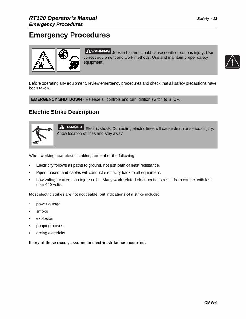
Emergency Procedures
Before operating any equipment, review emergency procedures and check that all safety precautions have been taken.
Electric Strike Description
When working near electric cables, remember the following:
• Electricity follows all paths to ground, not just path of least resistance.
• Pipes, hoses, and cables will conduct electricity back to all equipment.
• Low voltage current can injure or kill. Many work-related electrocutions result from contact with less than 440 volts.
Most electric strikes are not noticeable, but indications of a strike include:
• power outage
• smoke
• explosion
• popping noises
• arcing electricity
If any of these occur, assume an electric strike has occurred.
Jobsite hazards could cause death or serious injury. Use correct equipment and work methods. Use and maintain proper safety equipment.
EMERGENCY SHUTDOWN - Release all controls and turn ignition switch to STOP.
Electric shock. Contacting electric lines will cause death or serious injury. Know location of lines and stay away.

Safety - 14 RT120 Operator’s ManualEmergency Procedures
CMW®
If an Electric Line is Damaged
If you suspect an electric line has been damaged and you are near pedestrian unit, DO NOT MOVE and do not touch unit. Take the following actions. The order and degree of action will depend upon the situation.
• Warn people nearby that an electric strike has occurred. Instruct them to leave the area and contact utility.
• Do not allow anyone into area until given permission by utility company.
• Do not allow anyone to touch equipment.
If a Gas Line is Damaged
If you suspect a gas line has been damaged, take the following actions. The order and degree of action will depend on the situation.
• Immediately shut off engine(s), if this can be done safely and quickly.
• Remove any ignition source(s), if this can be done safely and quickly.
• Warn others that a gas line has been cut and that they should leave the area.
• Leave jobsite as quickly as possible.
• Immediately call your local emergency phone number and utility company.
• If jobsite is along street, stop traffic from driving near jobsite.
• Do not return to jobsite until given permission by emergency personnel and utility company.

RT120 Operator’s Manual Safety - 15Emergency Procedures
CMW®
If a Fiber Optic Cable is Damaged
Do not look into cut ends of fiber optic or unidentified cable. Vision damage can occur.
If Machine Catches on Fire
Perform emergency shutdown procedure and then take the following actions. The order and degree of action will depend on the situation.
• Immediately move battery disconnect switch (if equipped and accessible) to disconnect position.
• If fire is small and fire extinguisher is available, attempt to extinguish fire.
• If fire cannot be extinguished, leave area as quickly as possible and contact emergency personnel

Safety - 16 RT120 Operator’s ManualEmergency Procedures
CMW®
RT120 Operator’s Manual Safety - 17Safety Alert Classifications
CMW®
Safety Alert ClassificationsThese classifications and the icons defined on the following pages work together to alert you to situations which could be harmful to you, jobsite bystanders or your equipment. When you see these words and icons in the book or on the machine, carefully read and follow all instructions. YOUR SAFETY IS AT STAKE.
Watch for the three safety alert levels: DANGER, WARNING and CAUTION. Learn what each level means.
indicates a hazardous situation that, if not avoided, will result in death or serious injury. This signal word is to be limited to the most extreme situations.
indicates a hazardous situation that, if not avoided, could result in death or serious injury.
indicates a hazardous situation that, if not avoided, could result in minor or moderate injury.
Watch for two other words: NOTICE and IMPORTANT.
NOTICE indicates information considered important, but not hazard-related (e.g., messages relating to property damage).
IMPORTANT can help you do a better job or make your job easier in some way.

Safety - 18 RT120 Operator’s ManualMachine Safety Alerts
CMW®
Machine Safety Alerts
1
Runaway possible. Machine could run over you or others. Learn how to use all controls. Start and operate only from operator’s position.
2
Fall possible. Riders can fall from machine and be injured or killed. Only operator is allowed on machine.
3Moving parts could cut off hand or foot. Stay away.

RT120 Operator’s Manual Safety - 19Machine Safety Alerts
CMW®
4
Tiedown location. See Transport chapter for more information.
5
Rollover possible. If machine rolls over, you could be thrown from seat and killed or crushed. Wear seat belt.
6
Read operator’s manual. Know how to use all
controls before operating machine. When you see this sign on the machine or in the manual, read it and use caution. Your safety is at stake.
Safety - 20 RT120 Operator’s ManualAttachment Safety Alerts
CMW®
Attachment Safety Alerts
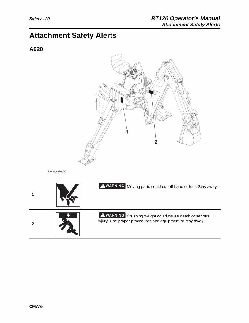
A920
1
Moving parts could cut off hand or foot. Stay away.
2
Crushing weight could cause death or serious injury. Use proper procedures and equipment or stay away.

RT120 Operator’s Manual Safety - 21Attachment Safety Alerts
CMW®
H910
1
Moving digging teeth will cause death or serious injury. Trench cave-in can cause you to fall. Stay away.
2
Tiedown location. See Transport chapter for more information.
3
Moving digging teeth will cause death or serious injury. Trench cave-in can cause you to fall. Stay away.
4
Lift point. See Transport chapter for more information.

Safety - 22 RT120 Operator’s ManualAttachment Safety Alerts
CMW®
H911
1
Moving digging teeth will cause death or serious injury. Trench cave-in can cause you to fall. Stay away.
2
Lift point. See Transport chapter for more information.
3Moving parts could cut off hand or foot. Stay away.
4
Tiedown location. See Transport chapter for more information.

RT120 Operator’s Manual Safety - 23Attachment Safety Alerts
CMW®
5
Moving digging teeth will cause death or serious injury. Trench cave-in can cause you to fall. Stay away.

Safety - 24 RT120 Operator’s ManualAttachment Safety Alerts
CMW®
H932
1
Tiedown location. See Transport chapter for more information.
2Moving parts could cut off hand or foot. Stay away.
3
Crushing weight could cause death or serious injury. Use proper procedures and equipment or stay away.
4
Lift point. See Transport chapter for more information.

RT120 Operator’s Manual Safety - 25Attachment Safety Alerts
CMW®
H952
1
Moving digging teeth will cause death or serious injury. Trench cave-in can cause you to fall. Stay away.
2
Tiedown location. See Transport chapter for more information.
3
Lift point. See Transport chapter for more information.
4
Crushing weight could cause death or serious injury. Use proper procedures and equipment or stay away.
5Moving parts could cut off hand or foot. Stay away.
Safety - 26 RT120 Operator’s ManualAttachment Safety Alerts
CMW®
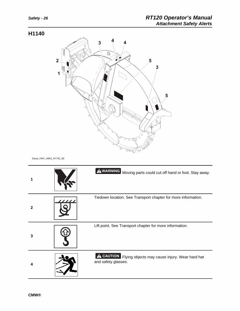
H1140
1Moving parts could cut off hand or foot. Stay away.
2
Tiedown location. See Transport chapter for more information.
3
Lift point. See Transport chapter for more information.
4
Flying objects may cause injury. Wear hard hat and safety glasses.

RT120 Operator’s Manual Safety - 27Attachment Safety Alerts
CMW®
RC120
5
Moving digging teeth will cause death or serious injury. Trench cave-in can cause you to fall. Stay away.
1
Lift point. See Transport chapter for more information.
2
Crushing weight could cause death or serious injury. Use proper procedures and equipment or stay away.

Safety - 28 RT120 Operator’s ManualAttachment Safety Alerts
CMW®

RT120 Operator’s Manual Controls - 29
CMW
Controls
Chapter Contents
Center Console . . . . . . . . . . . . . . . . . . . . . . . . . . . . 30
Graphic Display. . . . . . . . . . . . . . . . . . . . . . . . . . . . 34
Right Console . . . . . . . . . . . . . . . . . . . . . . . . . . . . . 47
Left Console . . . . . . . . . . . . . . . . . . . . . . . . . . . . . . 50
Seat Console . . . . . . . . . . . . . . . . . . . . . . . . . . . . . . 53
Seat Deck. . . . . . . . . . . . . . . . . . . . . . . . . . . . . . . . . 55
Trencher Controls. . . . . . . . . . . . . . . . . . . . . . . . . . 57
Plow Controls . . . . . . . . . . . . . . . . . . . . . . . . . . . . . 59
Combo Controls . . . . . . . . . . . . . . . . . . . . . . . . . . . 61
Backhoe Console . . . . . . . . . . . . . . . . . . . . . . . . . . 64
Saw Controls . . . . . . . . . . . . . . . . . . . . . . . . . . . . . . 68
Drill Controls . . . . . . . . . . . . . . . . . . . . . . . . . . . . . . 69
Battery Disconnect . . . . . . . . . . . . . . . . . . . . . . . . . 71
Controls - 30 RT120 Operator’s ManualCenter Console
CMW
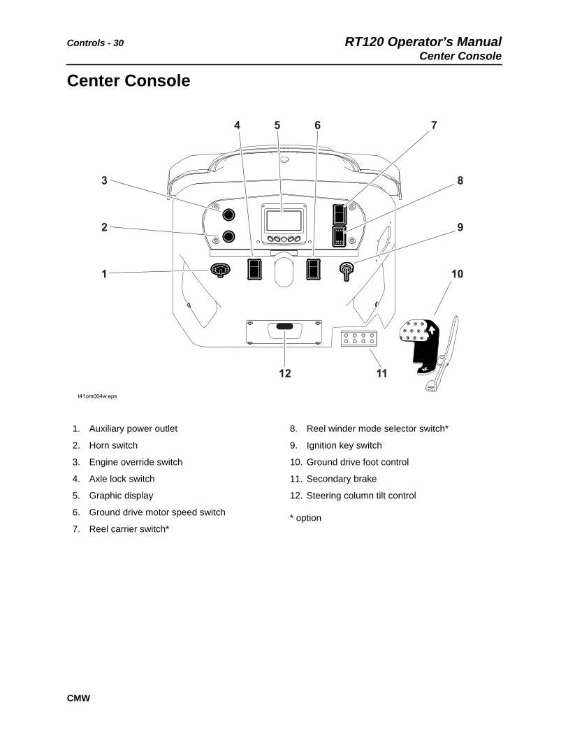
Center Console
1. Auxiliary power outlet
2. Horn switch
3. Engine override switch
4. Axle lock switch
5. Graphic display
6. Ground drive motor speed switch
7. Reel carrier switch*
8. Reel winder mode selector switch*
9. Ignition key switch
10. Ground drive foot control
11. Secondary brake
12. Steering column tilt control
* option
t41om004w.eps
1
2
3
4 5 6 7
8
9
10
12 11

RT120 Operator’s Manual Controls - 31Center Console
CMW
Item Description Notes
1. Auxiliary outlet Provides power for other equipment.
Power output is 12V, 10A.
2. Horn switch To sound horn, press.
3. Engine override switch For engine override, press.
4. Axle lock switch To lock rear axle, press top.
To unlock rear axle, press bottom.
NOTICE: To prevent mechanical damage, stop tractor before operating axle lock switch.
IMPORTANT: After pressing switch to unlock axle, it may be necessary to move tractor 6’ (2 m) in reverse to fully unlock.
c00ic179h.eps
c00ic044h.eps
c00ic024w.eps

Controls - 32 RT120 Operator’s ManualCenter Console
CMW
5. Graphic display Graphic symbols are displayed for indicators and conditions previously shown with gauges.
See more information in “Graphic Display” on page 34.
6. Ground drive motor speed switch
To select High or Low, press appropriate switch position.
Motor speed can be shifted while tractor is in motion.
Screen icon displays High or Low selection.
For more information see “Drive” on page 86.
7. Reel carrier switch To raise, press top.
To lower, press bottom.
Optional.
8. Reel winder mode selector switch
To change backfill blade joystick to reel winder control mode, press top.
To return to backfill blade mode, press bottom.
Optional.
Item Description Notes
c00ic604w.eps
!
c00ic044w.eps
H
L
c00ic205h.eps
c00ic642w.eps
RT120 Operator’s Manual Controls - 33Center Console
CMW
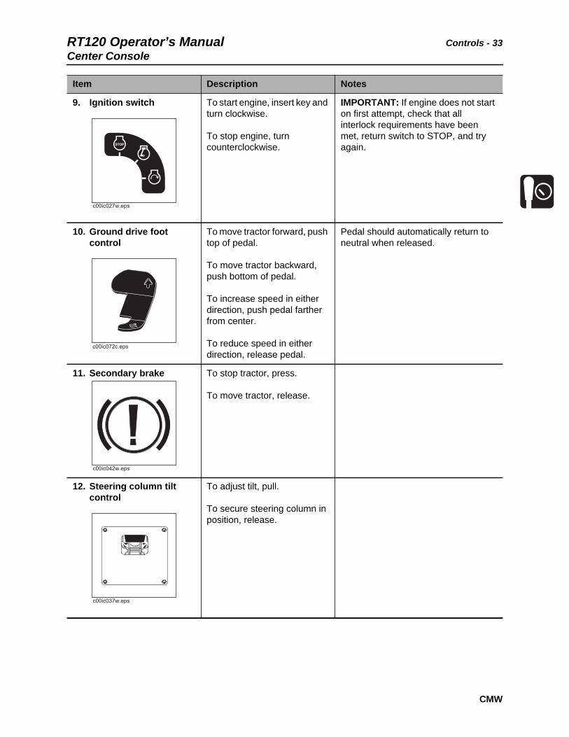
9. Ignition switch To start engine, insert key and turn clockwise.
To stop engine, turn counterclockwise.
IMPORTANT: If engine does not start on first attempt, check that all interlock requirements have been met, return switch to STOP, and try again.
10. Ground drive foot control
To move tractor forward, push top of pedal.
To move tractor backward, push bottom of pedal.
To increase speed in either direction, push pedal farther from center.
To reduce speed in either direction, release pedal.
Pedal should automatically return to neutral when released.
11. Secondary brake To stop tractor, press.
To move tractor, release.
12. Steering column tilt control
To adjust tilt, pull.
To secure steering column in position, release.
Item Description Notes
c00ic027w.eps
c00ic072c.eps
c00ic042w.eps
c00ic037w.eps

Controls - 34 RT120 Operator’s ManualGraphic Display
CMW
Graphic Display
The graphic display module shows engine RPM and has icons for other functions. Soft keys allow the operator to toggle between various screens and functions.
Item Description Notes
Attachment speed Displays percentage of attachment speed, and plow or trencher/saw mode.
Note: Screen icons change according to attachment being operated.
0
RPMx1000 %
0 % 0 %
0 F
0.0 v 0 PSI
0.0 H
15
5 2530
0
10 20
H H
t41om040w.eps
RPM00 00 AM/PM: 00:
c00ic028w.eps
RT120 Operator’s Manual Controls - 35Graphic Display
CMW
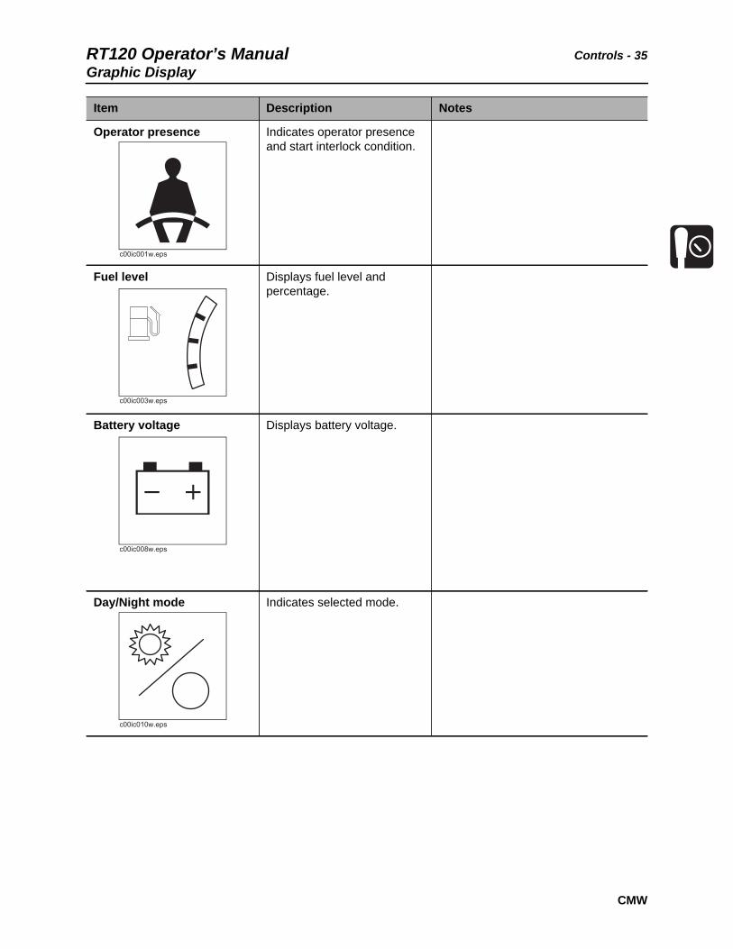
Operator presence Indicates operator presence and start interlock condition.
Fuel level Displays fuel level and percentage.
Battery voltage Displays battery voltage.
Day/Night mode Indicates selected mode.
Item Description Notes
c00ic001w.eps
c00ic003w.eps
c00ic008w.eps
c00ic010w.eps
Controls - 36 RT120 Operator’s ManualGraphic Display
CMW
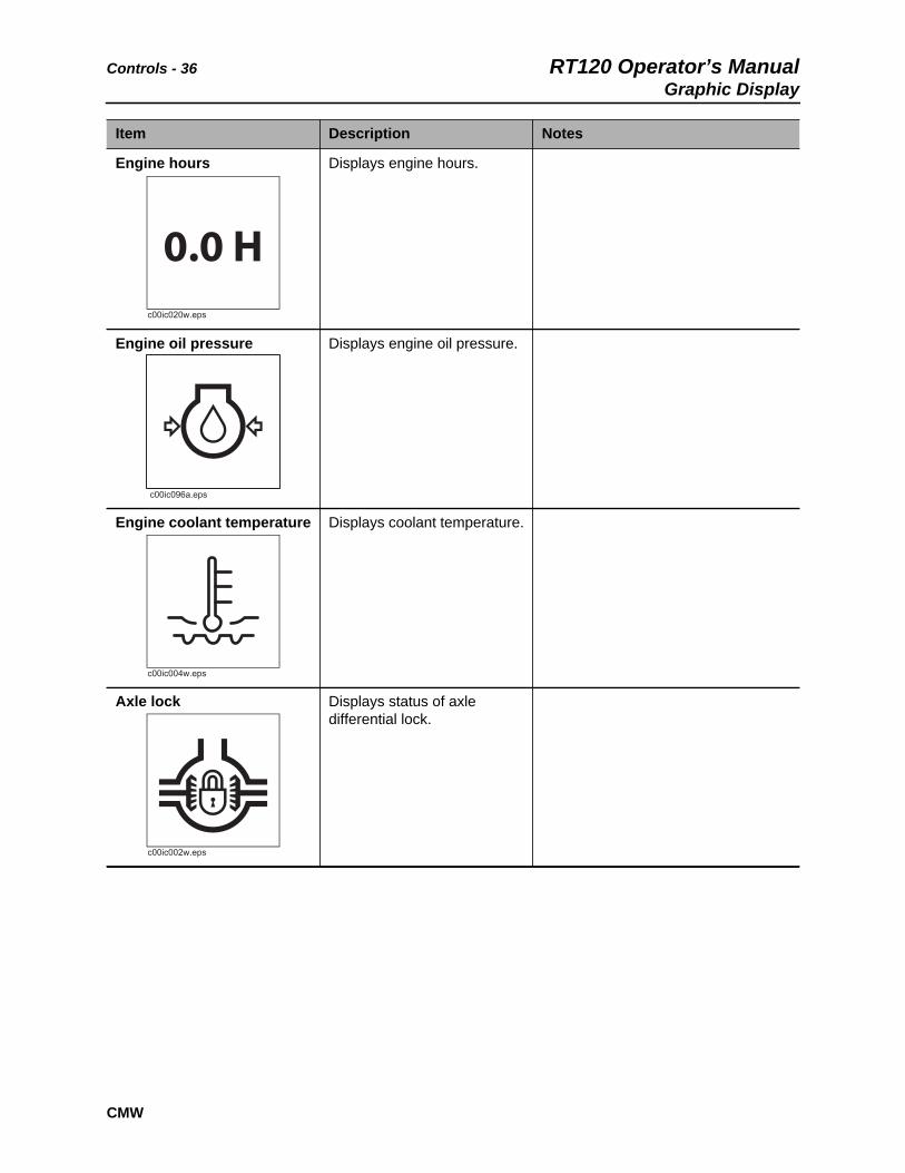
Engine hours Displays engine hours.
Engine oil pressure Displays engine oil pressure.
Engine coolant temperature Displays coolant temperature.
Axle lock Displays status of axle differential lock.
Item Description Notes
c00ic020w.eps
0.0 H
c00ic004w.eps
c00ic002w.eps
RT120 Operator’s Manual Controls - 37Graphic Display
CMW
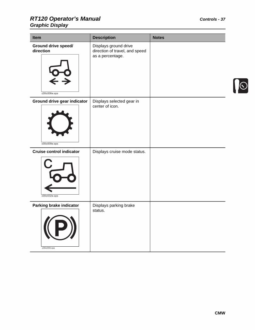
Item Description Notes
Ground drive speed/direction
Displays ground drive direction of travel, and speed as a percentage.
Ground drive gear indicator Displays selected gear in center of icon.
Cruise control indicator Displays cruise mode status.
Parking brake indicator Displays parking brake status.
c00ic006w.eps
c00ic009w.eps
c00ic032w.eps
c00ic055t.eps

Controls - 38 RT120 Operator’s ManualGraphic Display
CMW
Hydraulic filter restriction indicator
Displays restriction status.
Hydraulic fluid high temperature indicator
Displays hot fluid status.
Menu indicator Displays menu icon over key 3.
Item Description Notes
c00ic037t.eps
c00ic031w.eps

RT120 Operator’s Manual Controls - 39Graphic Display
CMW
Main Menu
Press the center soft key to display the main menu screen, which has icons for other functions. Soft keys below on screen icons allow the operator to toggle between various screens and functions.
Item Description Notes
System Settings This is an information display.
SYSTEMSETTINGS
USERSETTINGS
GAUGEDISPLAY
DIGNOSTICS
t33om093w.eps
c00ic015w.eps

Controls - 40 RT120 Operator’s ManualGraphic Display
CMW
User Settings Allows operator to customize settings.
Gauge Display Press the soft key below this on screen icon to select.
Diagnostics Displays interlock icons and diagnostic codes, if any.
Press soft key below on screen icons to return to main menu or gauge display.
Note: If diagnostic codes are displayed, contact your Ditch Witch dealer.
Item Description Notes
c00ic016w.eps
c00ic017w.eps
c00ic018w.eps
RT120 Operator’s Manual Controls - 41Graphic Display
CMW
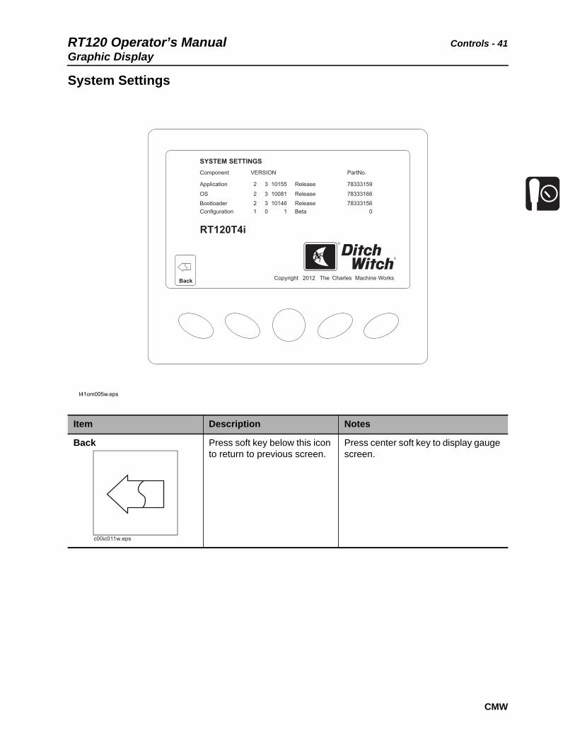
System Settings
Item Description Notes
Back Press soft key below this icon to return to previous screen.
Press center soft key to display gauge screen.
Back
t41om005w.eps
Copyright
Component
SYSTEM
RT120T4i
SETTINGS
Application
OS
Bootloader Configuration
2
2
21 1
3
3
3
10155
10081
101460 0
Release
Release
Release
78333159
78333166
78333156 Beta
VERSION Part No.
2012 The Charles Machine Works
c00ic011w.eps

Controls - 42 RT120 Operator’s ManualGraphic Display
CMW
User Settings
Item Description Notes
Back Press soft key below this icon to return to previous screen.
Press center soft key to display gauge screen.
Down Press soft key below this icon to toggle through selections 1-4.
Press center soft key to display gauge screen.
USER
Day
USA Standard Units
Language English
Ambient Light
100%Brightness
SETTINGS
t33om092w.eps
1
2
3
4
Back Save Reset
c00ic011w.eps
c00ic012w.eps

RT120 Operator’s Manual Controls - 43Graphic Display
CMW
Save Press soft key below this icon to save settings.
Reset Press soft key below this icon to return to default settings.
Day/Night Press soft key below this icon to select day or night mode.
Item Description Notes
c00ic013w.eps
c00ic014w.eps
c00ic010w.eps

Controls - 44 RT120 Operator’s ManualGraphic Display
CMW
Diagnostics
Note: If diagnostic codes are displayed, contact your Ditch Witch dealer.
Item Description Notes
Attachment Neutral Indicates attachment controls in neutral position.
MAIN DISPLAYGAUGE
MENU
t37om044w.eps
NN
c00ic021w.eps
N
RT120 Operator’s Manual Controls - 45Graphic Display
CMW
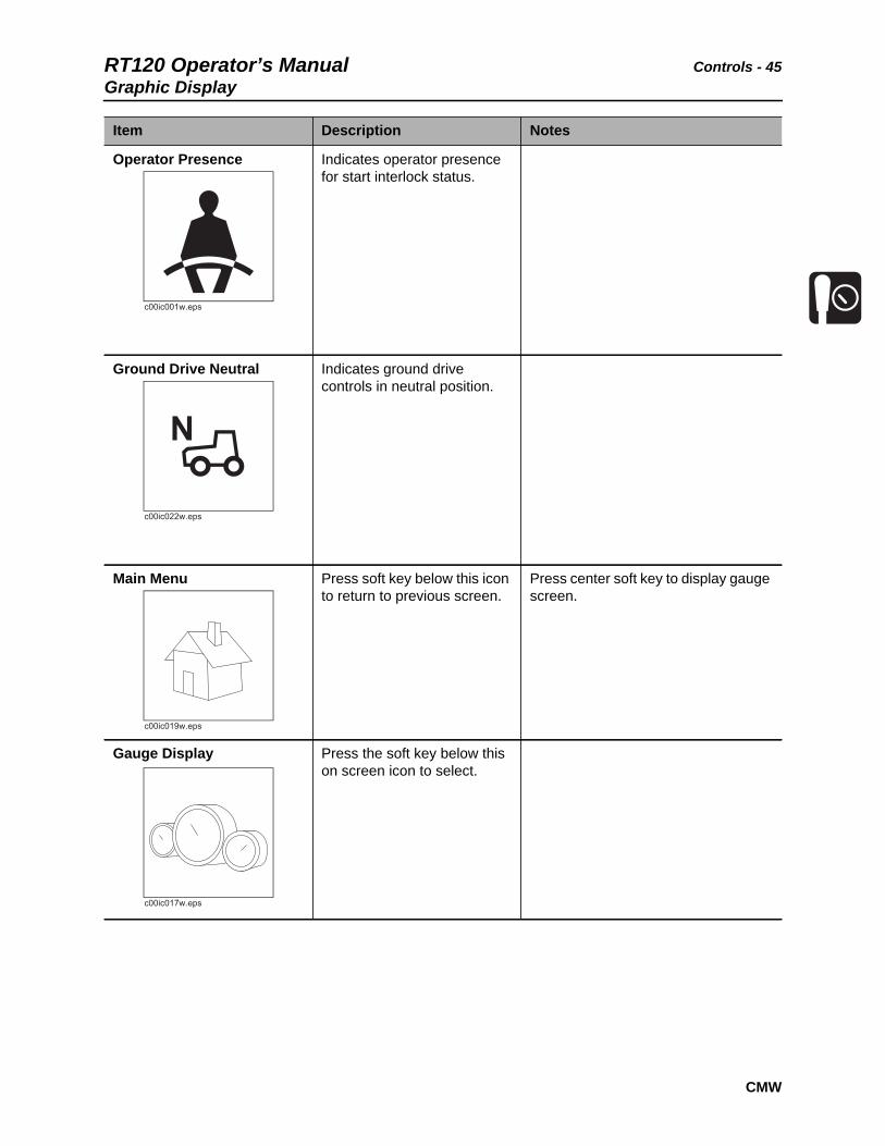
Operator Presence Indicates operator presence for start interlock status.
Ground Drive Neutral Indicates ground drive controls in neutral position.
Main Menu Press soft key below this icon to return to previous screen.
Press center soft key to display gauge screen.
Gauge Display Press the soft key below this on screen icon to select.
Item Description Notes
c00ic001w.eps
c00ic022w.eps
N
c00ic019w.eps
c00ic017w.eps

Controls - 46 RT120 Operator’s ManualGraphic Display
CMW
Engine stop Flashing icon indicates engine stop switch has been pressed from backhoe operator’s station.
Switch must be raised (reset) to allow engine starting.
Item Description Notes
c00ic649w.eps
RT120 Operator’s Manual Controls - 47Right Console
CMW
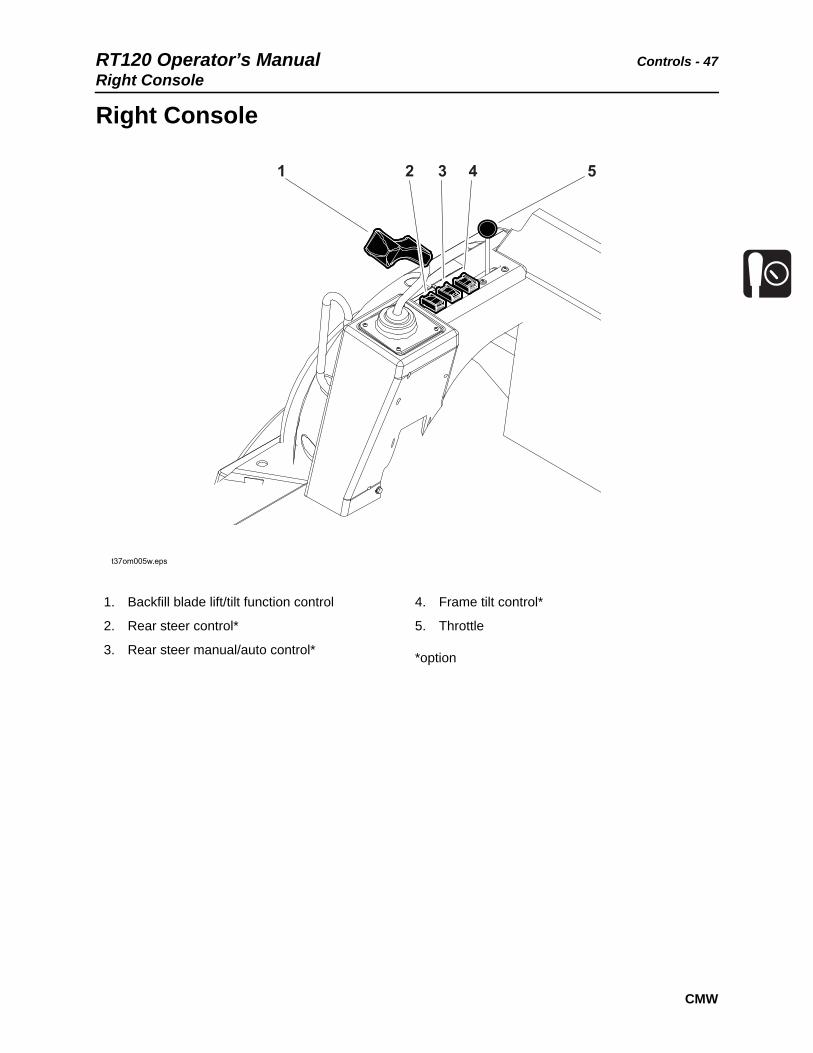
Right Console
1. Backfill blade lift/tilt function control
2. Rear steer control*
3. Rear steer manual/auto control*
4. Frame tilt control*
5. Throttle
*option
t37om005w.eps
1 2 3 4 5

Controls - 48 RT120 Operator’s ManualRight Console
CMW
Item Description Notes
1. Backfill blade lift/tilt function control
Backfill blade mode:
• To lower, move forward.
• To float, move forward to end.
• To raise, move backward.
• To tilt right side down, move right.
• To tilt left side down, move left.
Reel winder mode selector switch on center console changes function to control reel winder arm lift and winder direction.
Reel winder function control
Reel winder mode:
• To unwind, move forward.
• To wind, move backward.
• To lower reel winder arm, move right.
• To raise reel winder arm, move left.
2. Rear steer switch To move rear tires left, press left.
To move rear tires right, press right.
NOTICE:
• Tires move when you press the switch. To stop movement, release switch.
• Visually verify tire position
3. Rear steer manual/auto switch
To center tires, press left.
To manually steer rear tires, press right.
Use manual mode and the manual rear steer switch to bypass auto mode.
c00ic625w.eps
c00ic207h.eps

RT120 Operator’s Manual Controls - 49
CMW
4. Frame tilt control To tilt left, press left.
To tilt right, press right.
5. Throttle To increase speed, move forward.
To decrease speed, move rearward.
Item Description Notes
c00ic626w.eps
Controls - 50 RT120 Operator’s ManualLeft Console
CMW
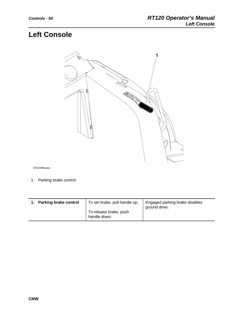
Left Console
1. Parking brake control
1. Parking brake control To set brake, pull handle up.
To release brake, push handle down.
Engaged parking brake disables ground drive.
1
t37om006w.eps
RT120 Operator’s Manual Controls - 51Rear Console
CMW
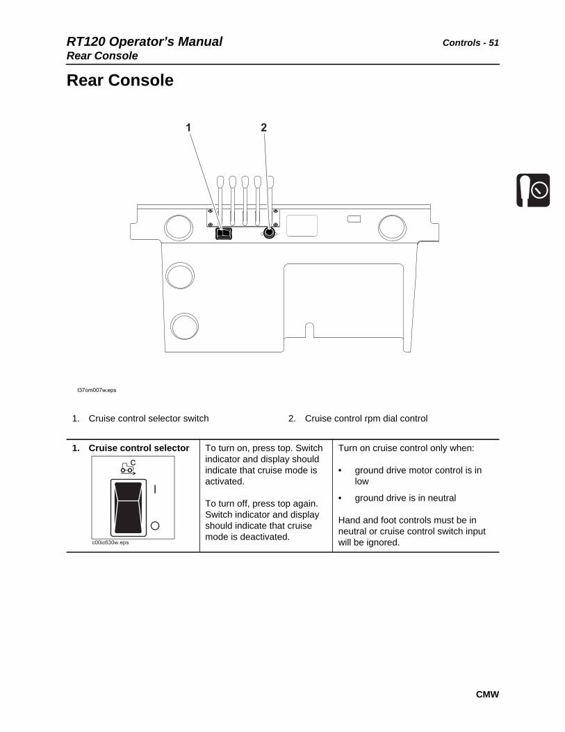
Rear Console
1. Cruise control selector switch 2. Cruise control rpm dial control
1. Cruise control selector To turn on, press top. Switch indicator and display should indicate that cruise mode is activated.
To turn off, press top again. Switch indicator and display should indicate that cruise mode is deactivated.
Turn on cruise control only when:
• ground drive motor control is in low
• ground drive is in neutral
Hand and foot controls must be in neutral or cruise control switch input will be ignored.
1 2
t37om007w.eps
c00ic630w.eps
Controls - 52 RT120 Operator’s Manual
CMW
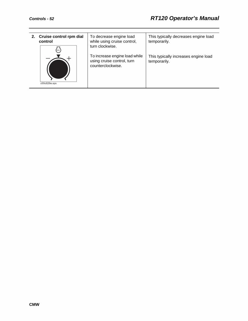
2. Cruise control rpm dial control
To decrease engine load while using cruise control, turn clockwise.
To increase engine load while using cruise control, turn counterclockwise.
This typically decreases engine load temporarily.
This typically increases engine load temporarily.
c00ic629w.eps
RPM

RT120 Operator’s Manual Controls - 53Seat Console
CMW
Seat Console
1. Ground drive speed/direction control
2. Attachment speed/direction control
3. Ground drive gear selector
Item Description Notes
1. Ground drive speed/direction control
To go faster in either direction, move farther from neutral.
To stop, return to center.
NOTICE: Control does not automatically return to neutral.
IMPORTANT: This control is disabled in high gear.
j26rg157h.jpg
11
22
3
c00ic631w.eps

Controls - 54 RT120 Operator’s ManualSeat Console
CMW
2. Attachment speed/direction control
To go faster in either direction, move farther from neutral.
To stop, return to center.
NOTICE: Control does not automatically return to neutral.
3. Ground drive gear selector
To select low speed, set to position 1.
To select high speed, set to position 2.
NOTICE: Tractor must be stopped before shifting.
Item Description Notes
c00ic632w.eps
c00ic043w.eps
1
2

RT120 Operator’s Manual Controls - 55Seat Deck
CMW
Seat Deck
1. Seat belt
2. Armrest adjustment control
3. Seat slide control
4. Seat height adjustment lock
5. Seat pivot control
Item Description Notes
1. Seat belt To fasten, insert latch into buckle. Adjust until seat belt is low and tight.
To release, lift top of buckle.
2. Armrest adjustment control
To raise or lower armrests:
• Remove knob.
• Adjust armrest to desired position.
• Replace knob.
11
22
22
11
34
45t33om003w.epst33om003w.eps
3
Controls - 56 RT120 Operator’s ManualSeat Deck
CMW
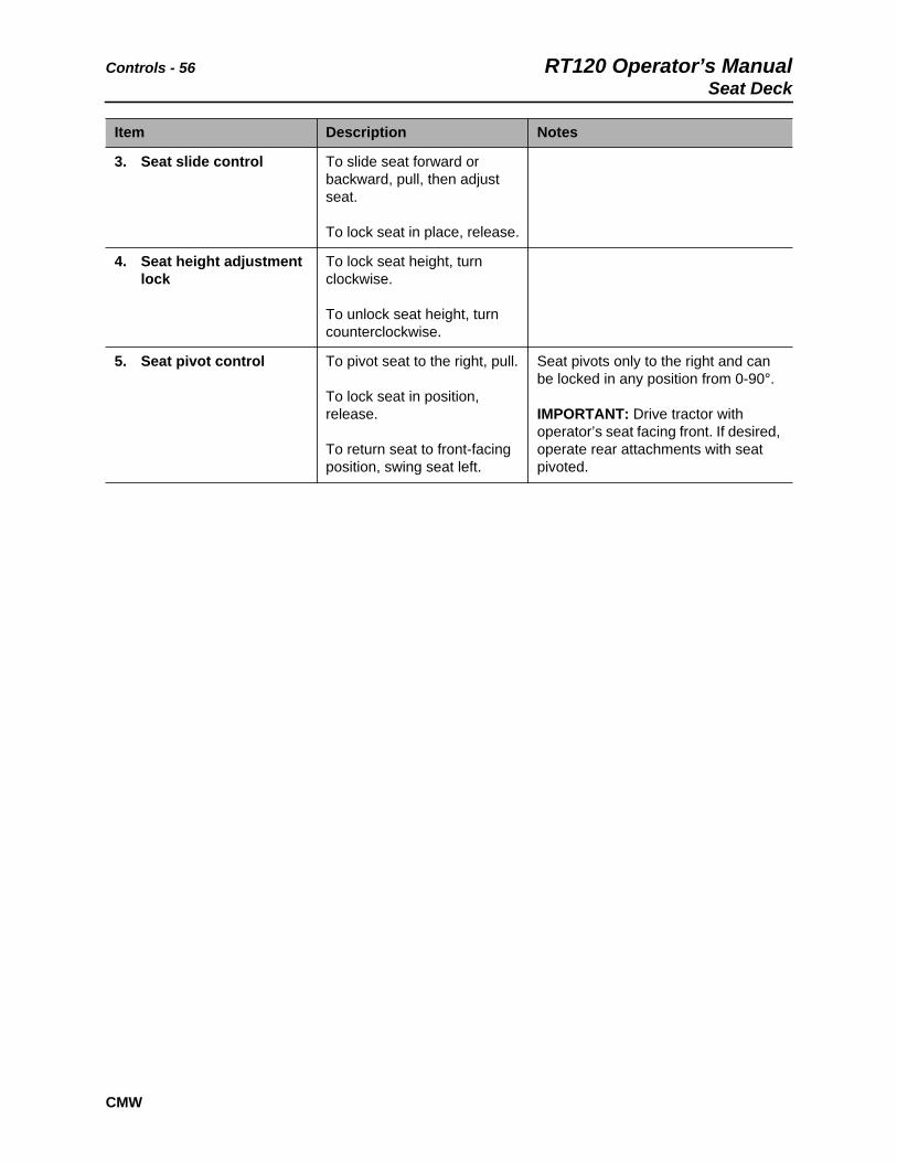
3. Seat slide control To slide seat forward or backward, pull, then adjust seat.
To lock seat in place, release.
4. Seat height adjustment lock
To lock seat height, turn clockwise.
To unlock seat height, turn counterclockwise.
5. Seat pivot control To pivot seat to the right, pull.
To lock seat in position, release.
To return seat to front-facing position, swing seat left.
Seat pivots only to the right and can be locked in any position from 0-90°.
IMPORTANT: Drive tractor with operator’s seat facing front. If desired, operate rear attachments with seat pivoted.
Item Description Notes

RT120 Operator’s Manual Controls - 57Trencher Controls
CMW
Trencher Controls
1. Trencher slide control*
2. Trench cleaner lift control*
3. Boom lift control
*optional
Item Description Notes
1. Trencher slide control (H911 only)
To slide trencher right, push.
To slide trencher left, pull.
1 2 3
t37om008w.eps
c00ic198h.eps
Controls - 58 RT120 Operator’s ManualTrencher Controls
CMW
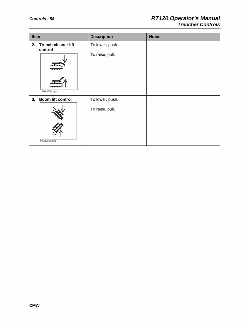
2. Trench cleaner lift control
To lower, push.
To raise, pull.
3. Boom lift control To lower, push.
To raise, pull.
Item Description Notes

RT120 Operator’s Manual Controls - 59Plow Controls
CMW
Plow Controls
1. Plow swing control
2. Blade steer control
3. Plow lift control
4. Stow lock control
Item Description Notes
1. Plow swing control To swing left, pull.
To swing right, push.
To float, push to end.
NOTICE:
• If soil conditions allow, operate in float position.
• Lower plow into ground before moving control to float position.
• Do not raise plow with control in float position.
1 2 3 4
t37om009w.eps
c00ic202h.eps
Controls - 60 RT120 Operator’s ManualPlow Controls
CMW
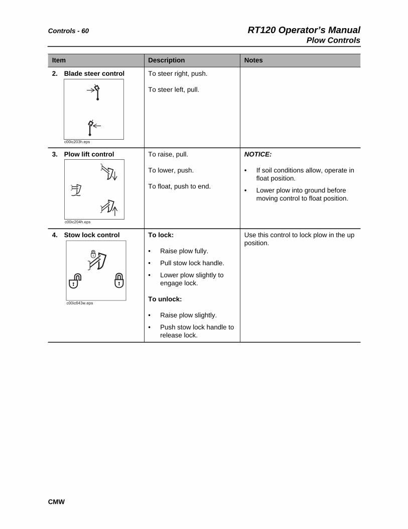
2. Blade steer control To steer right, push.
To steer left, pull.
3. Plow lift control To raise, pull.
To lower, push.
To float, push to end.
NOTICE:
• If soil conditions allow, operate in float position.
• Lower plow into ground before moving control to float position.
4. Stow lock control To lock:
• Raise plow fully.
• Pull stow lock handle.
• Lower plow slightly to engage lock.
To unlock:
• Raise plow slightly.
• Push stow lock handle to release lock.
Use this control to lock plow in the up position.
Item Description Notes
c00ic203h.eps
c00ic204h.eps
c00ic643w.eps

RT120 Operator’s Manual Controls - 61Combo Controls
CMW
Combo Controls
1. Plow swing control
2. Blade steer control
3. Plow lift control
4. Boom lift control
5. Plow stow lock control
6. Trench / Plow switch
Item Description Notes
1. Plow swing control To swing left, pull.
To swing right, push.
To float, push to end.
NOTICE:
• If soil conditions allow, operate in float position.
• Lower plow into ground before moving control to float position.
• Do not raise plow with control in float position.
1 2 3 4 5 6
t37om010w.eps
c00ic202h.eps

Controls - 62 RT120 Operator’s ManualCombo Controls
CMW
2. Blade steer control To steer right, push.
To steer left, pull.
3. Plow lift control To raise, pull.
To lower, push.
To float, push to end.
NOTICE:
• If soil conditions allow, operate in float position.
• Lower plow into ground before moving control to float position.
4. Boom lift control To lower, push.
To raise, pull.
5. Plow stow lock control To lock:
• Raise plow fully.
• Pull stow lock handle.
• Lower plow slightly to engage lock.
To unlock:
• Raise plow slightly.
• Push stow lock handle to release lock.
Use this control to lock plow in the up position.
c00ic203h.eps
c00ic204h.eps
c00ic643w.eps

RT120 Operator’s Manual Controls - 63Combo Controls
CMW
6. Trench / Plow switch To trench, set switch to trench position.
To plow, set switch to plow position.
Controls - 64 RT120 Operator’s ManualBackhoe Console
CMW
Backhoe Console
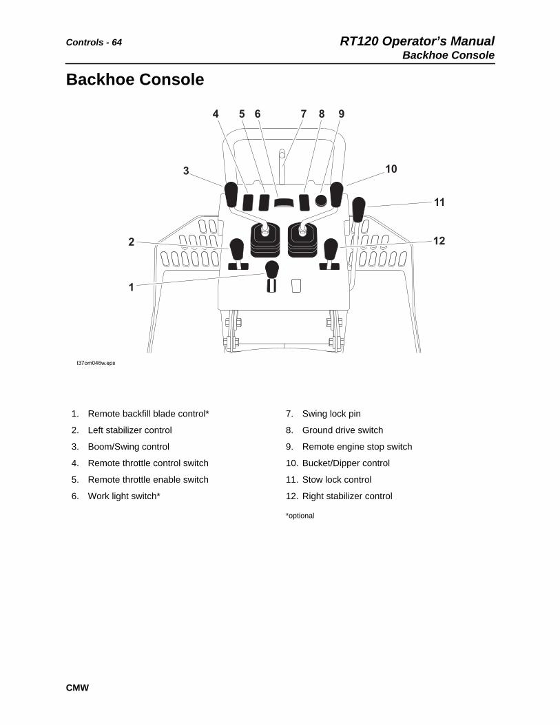
1. Remote backfill blade control*
2. Left stabilizer control
3. Boom/Swing control
4. Remote throttle control switch
5. Remote throttle enable switch
6. Work light switch*
7. Swing lock pin
8. Ground drive switch
9. Remote engine stop switch
10. Bucket/Dipper control
11. Stow lock control
12. Right stabilizer control
*optional
t37om046w.eps

RT120 Operator’s Manual Controls - 65Backhoe Console
CMW
Item Description Notes
1. Remote backfill blade control
To lower, push.
To raise, pull.
2. Left stabilizer control To lower, push out.
To raise, pull in.
3. Boom/Swing control To swing boom left, move left.
To swing boom right, move right.
To raise boom, pull.
To lower boom, push.
Control can perform more than one action at a time. By “feathering” the control, operator can combine backhoe operations.
NOTICE: Do not operate with backhoe in the stowed (upright) position.
4. Remote throttle To increase engine speed, press top.
To decrease engine speed, press bottom.
c00ic029w.eps

Controls - 66 RT120 Operator’s ManualBackhoe Console
CMW
5. Remote throttle enable To enable remote throttle control, press top.
To disable remote throttle control, press bottom.
Note: This switch must be returned to the OFF position for normal throttle control at tractor.
6. Work light switch To turn on, press right.
To turn off, press left.
7. Swing lock pin To lock:
• Engage stow lock.
• Insert swing lock pin into hole (1).
To release:
• Remove pin and store in hole (2).
• Release stow lock.
This pin locks boom from swinging during transport.
NOTICE: Do not store pin in holes marked with an “X.” Backhoe could swing and destroy pin.
8. Remote ground drive control
To move tractor forward, push.
To move tractor backward, pull.
NOTICE:
• This control is disabled if tractor seat is occupied.
• Tractor must be in low speed for remote ground drive to function.
• Ensure that backfill blade, if equipped, and stabilizers are raised before operating this control.
• Do not move more than 30’ (10 m) at a time.
Item Description Notes
c00ic030w.eps
c00ic216h.eps
RT120 Operator’s Manual Controls - 67Backhoe Console
CMW
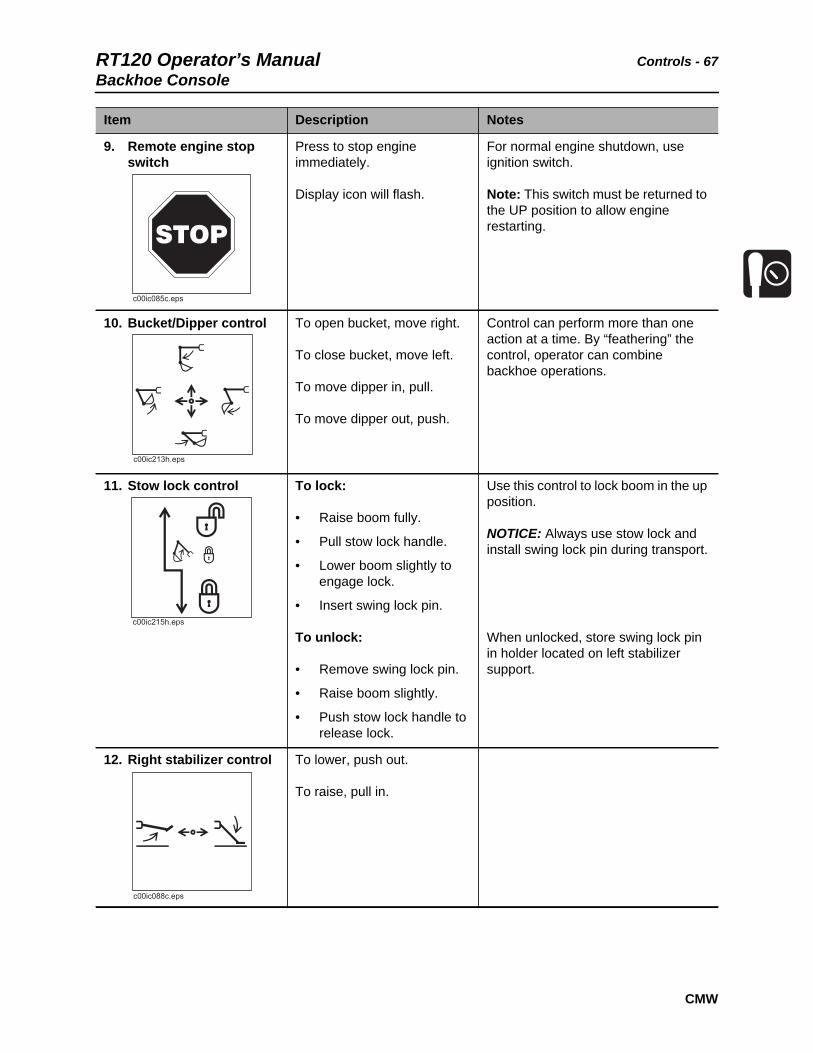
9. Remote engine stop switch
Press to stop engine immediately.
Display icon will flash.
For normal engine shutdown, use ignition switch.
Note: This switch must be returned to the UP position to allow engine restarting.
10. Bucket/Dipper control To open bucket, move right.
To close bucket, move left.
To move dipper in, pull.
To move dipper out, push.
Control can perform more than one action at a time. By “feathering” the control, operator can combine backhoe operations.
11. Stow lock control To lock:
• Raise boom fully.
• Pull stow lock handle.
• Lower boom slightly to engage lock.
• Insert swing lock pin.
To unlock:
• Remove swing lock pin.
• Raise boom slightly.
• Push stow lock handle to release lock.
Use this control to lock boom in the up position.
NOTICE: Always use stow lock and install swing lock pin during transport.
When unlocked, store swing lock pin in holder located on left stabilizer support.
12. Right stabilizer control To lower, push out.
To raise, pull in.
Item Description Notes

Controls - 68 RT120 Operator’s ManualSaw Controls
CMW
Saw Controls
1. Saw slide control 2. Saw lift control
Item Description Notes
1. Saw slide control To slide saw right, push.
To slide saw to center, pull.
1 2
t37om045w.eps

RT120 Operator’s Manual Controls - 69
CMW
2. Saw lift control To lower, push.
To raise, pull.
Item Description Notes
c00ic209h.eps

Controls - 70 RT120 Operator’s ManualDrill Controls
CMW
Drill Controls
1. Drilling attachment control 2. Drilling attachment
Item Description Notes
1. Drilling attachment control
To rotate clockwise, press bore.
To rotate counterclockwise, press reverse.
IMPORTANT: Always rotate clockwise during drilling and backreaming. Rotate counterclockwise only to dislodge a dry bore bit or reamer that has seized in the bore hole.
Switch should return to neutral position when released.
t33om063w.eps
2
1
c00ic655w.eps

RT120 Operator’s Manual Controls - 71Battery Disconnect
CMW
Battery Disconnect
1. Battery disconnect switch
Item Description Notes
1. Battery disconnect switch
To connect, move left.
To disconnect, move right.
NOTICE: Do not operate battery switch with engine running.
t41om007w.eps
1
c00ic063t.eps
+_
+_

Controls - 72 RT120 Operator’s Manual
CMW

RT120 Operator’s Manual Operation Overview - 73
CMW
Operation Overview
Chapter Contents
Planning. . . . . . . . . . . . . . . . . . . . . . . . . . . . . . . . . . 74
Trenching. . . . . . . . . . . . . . . . . . . . . . . . . . . . . . . . . 74
Plowing . . . . . . . . . . . . . . . . . . . . . . . . . . . . . . . . . . 74
Drilling . . . . . . . . . . . . . . . . . . . . . . . . . . . . . . . . . . . 74
Digging with Backhoe . . . . . . . . . . . . . . . . . . . . . . 75
Sawing . . . . . . . . . . . . . . . . . . . . . . . . . . . . . . . . . . . 75
Leaving Jobsite. . . . . . . . . . . . . . . . . . . . . . . . . . . . 75

Operation Overview - 74 RT120 Operator’s ManualPlanning
CMW
Planning1. Gather information about jobsite. See page 78.
2. Inspect jobsite. See page 79.
3. Classify jobsite. See page 80.
4. Select chain and teeth to match your soil type, if necessary. See page 148
5. Check supplies and prepare equipment. See page 82.
6. Haul equipment to jobsite. See page 96.
Trenching1. Start unit. See page 84.
2. Position tractor and controls. See page 103.
3. Begin trenching. See page 104.
4. Engage cruise control if desired. See page 146.
5. Complete the installation. See page 151.
6. Shut down tractor. See page 88.
Plowing1. Start unit. See page 84.
2. Position tractor and controls. See page 110.
• offset plowing - page 117
• coordinated plowing - page 117
• crabbing - page 117
3. Attach product. See page 111.
4. Begin plowing. See page 113.
5. Engage cruise control if desired. See page 146.
6. Complete the installation. See page 151.
7. Shut down tractor. See page 88.
Drilling1. Start unit. See page 84.
2. Dig approach trench and target trench. See page 131.
3. Assemble drill string and position tractor. See page 132.

RT120 Operator’s Manual Operation Overview - 75Digging with Backhoe
CMW
4. Begin drilling. See page 133.
5. Use drill string guide as needed. See page 134.
6. Add rod. See page 135.
7. Backream. See page 135.
8. Shut down tractor. See page 88.
9. Disassemble joints. See page 136.
Digging with Backhoe1. Start unit. See page 84.
2. Set stabilizers and unstow backhoe. See page 124.
3. Excavate. See page 125.
4. Stow backhoe properly. See page 126.
5. Shut down tractor. See page 88.
Sawing1. Start unit. See page 84.
2. Position tractor and controls. See page 138.
3. Begin sawing. See page 140.
4. Complete the installation. See page 151.
5. Backfill the trench. See page 152.
6. Shut down tractor. See page 88.
Leaving Jobsite1. Backfill if necessary. See page 152.
2. Rinse equipment. See page 152.
3. Stow tools. See page 152.
4. Haul equipment from jobsite. See page 96.

Operation Overview - 76 RT120 Operator’s ManualLeaving Jobsite
CMW

RT120 Operator’s Manual Prepare - 77
CMW
Prepare
Chapter Contents
Gather Information . . . . . . . . . . . . . . . . . . . . . . . . . 78
• Review Job Plan . . . . . . . . . . . . . . . . . . . . . . . . . . . . . . . . . . . . . . . . . . 78
• Notify One-Call Services . . . . . . . . . . . . . . . . . . . . . . . . . . . . . . . . . . . . 78
• Arrange for Traffic Control. . . . . . . . . . . . . . . . . . . . . . . . . . . . . . . . . . . 78
• Plan for Emergency Services . . . . . . . . . . . . . . . . . . . . . . . . . . . . . . . . 78
Inspect Site . . . . . . . . . . . . . . . . . . . . . . . . . . . . . . . 79
• Identify Hazards . . . . . . . . . . . . . . . . . . . . . . . . . . . . . . . . . . . . . . . . . . 79
Classify Jobsite. . . . . . . . . . . . . . . . . . . . . . . . . . . . 80
• Inspect Jobsite . . . . . . . . . . . . . . . . . . . . . . . . . . . . . . . . . . . . . . . . . . . 80
• Select a Classification . . . . . . . . . . . . . . . . . . . . . . . . . . . . . . . . . . . . . . 80
• Apply Precautions . . . . . . . . . . . . . . . . . . . . . . . . . . . . . . . . . . . . . . . . . 81
Check Supplies and Prepare Equipment . . . . . . . 82
• Supplies . . . . . . . . . . . . . . . . . . . . . . . . . . . . . . . . . . . . . . . . . . . . . . . . 82
• Fluid Levels . . . . . . . . . . . . . . . . . . . . . . . . . . . . . . . . . . . . . . . . . . . . . . 82
• Condition and Function . . . . . . . . . . . . . . . . . . . . . . . . . . . . . . . . . . . . . 82
• Accessories. . . . . . . . . . . . . . . . . . . . . . . . . . . . . . . . . . . . . . . . . . . . . . 82

Prepare - 78 RT120 Operator’s ManualGather Information
CMW
Gather InformationA successful job begins before you dig. The first step in planning is reviewing information already available about the job and jobsite.
Review Job Plan
Review blueprints or other plans. Check for information about existing or planned structures, elevations, or proposed work that may be taking place at the same time.
Notify One-Call Services
Contact your local One-Call (811 in USA) or the One-Call referral number (888-258-0808 in USA and Canada) to have underground utilities located before digging. Also contact any utilities that do not participate in the One-Call service.
Arrange for Traffic Control
If working near a road or other traffic area, contact local authorities about safety procedures and regulations.
Plan for Emergency Services
Have the telephone numbers for local emergency and medical facilities on hand. Check that you will have access to a telephone.

RT120 Operator’s Manual Prepare - 79Inspect Site
CMW
Inspect SiteInspect jobsite before transporting equipment. Check for the following:
• changes in elevation such as hills or other open trenches
• obstacles such as buildings, railroad crossings, or streams
• signs of utilities
• traffic
• access
• soil type and condition
Identify Hazards
Identify safety hazards and classify jobsite. See “Classify Jobsite” on page 80.
Jobsite hazards could cause death or serious injury. Use correct equipment and work methods. Use and maintain proper safety equipment.
To Help Avoid Injury:
• Wear personal protective equipment including hard hat, safety eye wear, and hearing protection.
• Do not wear jewelry or loose clothing.
• Notify One-Call and companies which do not subscribe to One-Call.
• Comply with all utility notification regulations before digging or drilling.
• Verify location of previously marked underground hazards.
• Mark jobsite clearly and keep spectators away.
Remember, jobsite is classified by hazards in place -- not by line being installed.

Prepare - 80 RT120 Operator’s ManualClassify Jobsite
CMW
Classify Jobsite
Inspect Jobsite
• Follow U.S. Department of Labor regulations on excavating and trenching (Part 1926, Subpart P) and other similar regulations.
• Contact your local One-Call (811 in USA) or the One-Call referral number (888-258-0808 in USA and Canada) to have underground utilities located before digging. Also contact any utilities that do not participate in the One-Call service.
• Inspect jobsite and perimeter for evidence of underground hazards, such as:
– “buried utility” notices
– utility facilities without overhead lines
– gas or water meters
– junction boxes
– drop boxes
– light poles
– manhole covers
– sunken ground
• Have an experienced locating equipment operator sweep area within 20’ (6 m) to each side of trench path. Verify previously marked line and cable locations.
• Mark location of all buried utilities and obstructions.
• Classify jobsite.
Select a Classification
Jobsites are classified according to underground hazards present.
If working... then classify jobsite as...
within 10’ (3 m) of a buried electric line electric
within 10’ (3 m) of a natural gas line natural gas
in sand, granite, or concrete which is capable of producing crystalline silica (quartz) dust
crystalline silica (quartz) dust
within 10’ (3 m) of any other hazard other
NOTICE: If you have any doubt about jobsite classification, or if jobsite might contain unmarked hazards, take steps outlined previously to identify hazards and classify jobsite before working.

RT120 Operator’s Manual Prepare - 81Classify Jobsite
CMW
Apply Precautions
Once classified, precautions appropriate for jobsite must be taken.
Electric Jobsite Precautions
Use one or both of these methods.
• Expose line by careful hand digging or soft excavation.
• Have service shut down while work is in progress. Have electric company test lines before returning them to service.
Natural Gas Jobsite Precautions
In addition to positioning equipment upwind from gas lines, use one or both of these methods.
• Expose lines by careful hand digging or soft excavation.
• Have gas shut off while work is in progress. Have gas company test lines before returning them to service.
Crystalline Silica (Quartz) Dust Precautions
Crystalline silica dust is a naturally occurring substance found in soil, sand, concrete, granite, and quartz. Breathing silica dust particles while cutting, drilling, or working materials may cause lung disease or cancer. To reduce exposure:
• Use water spray or other means to control dust.
• Refer to U.S. Department of Labor Occupational Safety and Health Administration guidelines to learn more about appropriate breathing protection and permissible exposure limits.
Other Jobsite Precautions
You may need to use different methods to safely avoid other underground hazards. Talk with those knowledgeable about hazards present at each site to determine which precautions should be taken or if job should be attempted.

Prepare - 82 RT120 Operator’s ManualCheck Supplies and Prepare Equipment
CMW
Check Supplies and Prepare Equipment
Supplies
• fuel
• keys
• personal protective equipment, such as hard hat and safety glasses
Fluid Levels
• fuel
• hydraulic fluid
• battery charge
• engine oil
Condition and Function
• digging chain and teeth
• brake pads and disc
• fan belts
• light bulbs
• filters (air, oil, hydraulic)
• tires
• pumps and motors
• hoses and valves
• signs, guards, and shields
Accessories
Fire Extinguisher
If required, mount a fire extinguisher near the power unit but away from possible points of ignition. The fire extinguisher should always be classified for both oil and electric fires. It should meet legal and regulatory requirements.

RT120 Operator’s Manual Drive - 83
CMW
Drive
Chapter Contents
Start Unit . . . . . . . . . . . . . . . . . . . . . . . . . . . . . . . . . 84
Drive . . . . . . . . . . . . . . . . . . . . . . . . . . . . . . . . . . . . . 86
Safe Slope Operation . . . . . . . . . . . . . . . . . . . . . . . 87
Shut Down . . . . . . . . . . . . . . . . . . . . . . . . . . . . . . . . 88

Drive - 84 RT120 Operator’s ManualStart Unit
CMW
Start UnitBefore operating tractor, read engine manufacturer’s starting and operating instructions. Follow instructions for new engine break-in.
Read operator’s manual. Know how to use all controls before operating
machine. When you see this sign on the machine or in the manual, read it and use caution. Your safety is at stake.
To help avoid injury:
• Read operator’s manual before operating equipment. Follow instructions carefully. Contact Ditch Witch dealership for operation information or demonstration.
• Wear hard hat, safety glasses, and other protective equipment required by job. Do not wear jewelry or loose clothing that can catch on controls.
Runaway possible. Machine could run over you or others. Learn how to use all controls. Start and operate only from operator’s position.
Rollover possible. If machine rolls over, you could be thrown from seat and killed or crushed. Wear seat belt.

RT120 Operator’s Manual Drive - 85Start Unit
CMW
1. Fasten and adjust seat belt.
2. Check that ground drive control and attachment speed/direction control are in neutral.
3. Move throttle to idle.
4. Verify that parking brake is engaged.
5. Turn ignition switch to the run position (key on, engine off). Cold start wait indicator will light (if equipped).
6. When cold start wait indicator goes off, turn ignition switch all the way clockwise to start tractor. Warning alarm will sound. Indicators will light.
• If engine does not crank, check start interlock display.
• If engine turns but does not start within 10 seconds, allow starter to cool before trying to start again.
7. Run engine at half-throttle or less for five minutes before operating tractor. During warm up, check that all controls work properly.
Explosion possible. Serious injury or equipment damage could occur. Follow directions carefully.
To help avoid injury: Do not use ether or any other type of aerosol starting fluid when unit is equipped with cold start option.
Improper control function could cause death or serious injury.
To help avoid injury: Stop machine and have it serviced if control does not work as described in instructions.
IMPORTANT: Machine will not start if start interlock requirements are not met.
Drive - 86 RT120 Operator’s ManualDrive
CMW
Drive
General Operation
1. Turn on lights as needed.
2. Raise backfill blade and all attachments.
3. Release parking brake.
4. Adjust throttle.
5. When operating in low:
• if using the hand control, the foot control will only increase speed.
• any opposing signal from controls causes ground drive to stop.
6. When operating in high, ground drive stops if hand control is moved out of neutral position.
Moving traffic – hazardous situation. Death or serious injury could result. Avoid moving vehicles, wear high visibility clothing, post appropriate warning signs.
To help avoid injury:
• Drive carefully in congested areas. Know machine’s clearance and turning radius.
• Keep attachments low when operating on slope. Drive slowly and cautiously.
EMERGENCY SHUTDOWN: Turn ignition switch to STOP.

RT120 Operator’s Manual Drive - 87Drive
CMW
Safe Slope Operation
Operating safely on a slope depends upon many factors including:
• Distribution of machine weight, including front loading and absence of load
• Height of load
• Even or rough ground conditions
• Potential for ground giving way causing unplanned tilt forward, reverse or sideways
• Nearness of ditches, ruts, stumps or other obstructions and sudden changes in slope
• Speed
• Turning
• Braking performance
• Operator skill
These varying factors make it impractical to specify a maximum safe operating angle in this manual. It is therefore important for the operator to be aware of these conditions and adjust operation accordingly.
Tipover possible. Machine can tip over and crush you.
To help avoid injury:
• Always operate with heavy end uphill.
• Drive cautiously at all times.
• Never jerk control levers. Use a steady even motion.
• Do not park unit on slope without lowering digging attachment to the ground, returning all controls to neutral position, shutting down unit, and applying parking brake.

Drive - 88 RT120 Operator’s ManualShut Down
CMW
Shut Down1. When job is complete, move ground drive control to neutral.
2. Engage parking brake and verify parking brake indicator is on.
3. Lower all attachments to ground and let machine idle for three minutes to cool.
4. Turn ignition switch to STOP. If leaving machine unattended, remove key.
5. For maintenance or long-term storage, turn battery disconnect switch to disconnect position.

RT120 Operator’s Manual Transport - 89
CMW
Transport
Chapter Contents
Lift . . . . . . . . . . . . . . . . . . . . . . . . . . . . . . . . . . . . . . 90
• Points . . . . . . . . . . . . . . . . . . . . . . . . . . . . . . . . . . . . . . . . . . . . . . . . . . 90
• Procedure . . . . . . . . . . . . . . . . . . . . . . . . . . . . . . . . . . . . . . . . . . . . . . . 90
Tie Down . . . . . . . . . . . . . . . . . . . . . . . . . . . . . . . . . 93
• Points . . . . . . . . . . . . . . . . . . . . . . . . . . . . . . . . . . . . . . . . . . . . . . . . . . 93
• Procedure . . . . . . . . . . . . . . . . . . . . . . . . . . . . . . . . . . . . . . . . . . . . . . . 93
Haul . . . . . . . . . . . . . . . . . . . . . . . . . . . . . . . . . . . . . 96
• Procedure . . . . . . . . . . . . . . . . . . . . . . . . . . . . . . . . . . . . . . . . . . . . . . . 96
Tow . . . . . . . . . . . . . . . . . . . . . . . . . . . . . . . . . . . . . 99
• Procedure . . . . . . . . . . . . . . . . . . . . . . . . . . . . . . . . . . . . . . . . . . . . . . . 99

Transport - 90 RT120 Operator’s ManualLift
CMW
Lift
Points
Lifting points are identified by lifting decals. Lifting at other points is unsafe and can damage machinery.
Procedure
Tractor
This machine is not configured for lifting. If the machine must be lifted, load machine into a container or onto a platform appropriate for lifting. See “Specifications” on page 197 for size and weight of machine.
Crushing weight. If load falls or moves it could kill or crush you. Use proper procedures and equipment or stay away.
Read operator’s manual. Know how to use all controls before operating
machine. When you see this sign on the machine or in the manual, read it and use caution. Your safety is at stake.

RT120 Operator’s Manual Transport - 91Lift
CMW
Centerline Trencher
Use crane capable of supporting the equipment's size and weight. See “Specifications” on page 197 or measure and weigh equipment before lifting.
Traversing Trencher
Use crane capable of supporting the equipment's size and weight. See “Specifications” on page 197 or measure and weigh equipment before lifting.
Combo
Use crane capable of supporting the equipment’s size and weight. See “Specifications” on page 197 or measure and weigh equipment before lifting.

Transport - 92 RT120 Operator’s ManualLift
CMW
Plow
Use crane capable of supporting the equipment's size and weight. See “Specifications” on page 197 or measure and weigh equipment before lifting.
Reel Carrier
Use crane capable of supporting the equipment's size and weight. See page 197 or measure and weigh equipment before lifting.
RT120 Operator’s Manual Transport - 93Tie Down
CMW
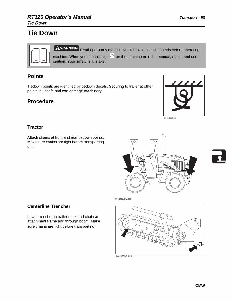
Tie Down
Points
Tiedown points are identified by tiedown decals. Securing to trailer at other points is unsafe and can damage machinery.
Procedure
Tractor
Attach chains at front and rear tiedown points. Make sure chains are tight before transporting unit.
Centerline Trencher
Lower trencher to trailer deck and chain at attachment frame and through boom. Make sure chains are tight before transporting.
Read operator’s manual. Know how to use all controls before operating
machine. When you see this sign on the machine or in the manual, read it and use caution. Your safety is at stake.
t41om008w.eps

Transport - 94 RT120 Operator’s ManualTie Down
CMW
Traversing Trencher
Lower trencher to trailer deck and chain at attachment frame and through boom. Make sure chains are tight before transporting.
Combo
Lower attachment to trailer deck and chain at attachment frame and vibrator box. Make sure chains are tight before transporting.
NOTICE:
• Engage attachment stow lock and swing lock devices in addition to securing at tiedowns.
• Unsecured plow can swing outside the trailer and become a traffic hazard. Lower plow and chain to trailer deck before hauling.

RT120 Operator’s Manual Transport - 95Tie Down
CMW
Plow
Lower plow to trailer deck and chain at attachment frame and vibrator box. Make sure chains are tight before transporting.
Reel Carrier
Lower reel carrier to lowest position and tie down at attachment arms. Make sure chains are tight before transporting.
NOTICE:
• Engage attachment stow lock and swing lock devices in addition to securing at tiedowns.
• Unsecured plow can swing outside the trailer and become a traffic hazard. Lower plow and chain to trailer deck before hauling.

Transport - 96 RT120 Operator’s ManualHaul
CMW
Haul
Procedure
Inspect Trailer
1. Check hitch for wear and cracks. Lubricate if needed.
2. Check battery for 12V charge.
3. Inspect lights for cleanliness and correct operation. Inspect reflectors and replace if needed.
4. Check trailer tire pressure. Check lug nut torque with a torque wrench. Adjust if needed.
5. Ensure trailer brakes are adjusted to come on in synchronization with tow vehicle brakes.
6. Check ramps and trailer bed for cracks.
Read operator’s manual. Know how to use all controls before operating
machine. When you see this sign on the machine or in the manual, read it and use caution. Your safety is at stake.
To help avoid injury:
• Read trailer operator’s manual before loading or transporting your machine. Incorrectly loaded machine can slip or cause trailer sway.
• Ensure that tow vehicle has proper tow capacity rating.
• Attach trailer to tow vehicle before loading or unloading.
• Park, load, and unload trailer on level ground.
• Check that unit and trailer do not exceed size or weight regulations.
• Load trailer correctly to avoid trailer sway. Ten to fifteen percent of total vehicle weight (equipment plus trailer) must be on tongue to help prevent trailer sway.
• Connect safety chains to tow vehicle. Attach left chain to right side of tow vehicle and vice versa to cradle hitch. Do not connect to pintle hook or hitch ball.
• Connect breakaway switch cable to tow vehicle. Do not connect to pintle hook or hitch ball.
RT120 Operator’s Manual Transport - 97Haul
CMW
Load
1. Fasten and adjust seat belt.
2. Tilt steering column down.
3. Start tractor. See page 84 for proper start-up procedures.
4. Raise attachments, but keep them low and centered. Check that they are not in float.
5. Release parking brake and verify that parking brake indicator is off.
6. Move ground drive gear selector to position 1 and motor speed switch to low.
7. Slow engine to low throttle and slowly drive tractor onto trailer.
8. Position tractor on trailer deck for proper weight distribution.
9. Engage parking brake and verify that parking brake indicator is on.
10. Lower attachments to trailer bed and turn tractor off. See page 88 for proper shutdown procedures.
11. Attach chains to tractor and attachments where tiedown decals are located. See page 93.
Crushing weight. If load falls or moves it could kill or crush you. Use proper procedures and equipment or stay away.
To help avoid injury:
• Attach trailer to tow vehicle before loading or unloading.
• Load and unload trailer on level ground.
• Block trailer wheels.
• Put ground drive control into neutral. Turn off ignition. Set parking brake.
Rollover possible. If machine rolls over, you could be thrown from seat and killed or crushed. Wear seat belt.

Transport - 98 RT120 Operator’s ManualHaul
CMW
Unload
1. Lower trailer or ramps.
2. Check that parking brake is engaged and verify that parking brake indicator is on.
3. Check that ground drive controls are in neutral.
4. Remove chains from tiedowns.
5. Fasten and adjust seat belt.
6. Tilt steering column down.
7. Start tractor. See page 84 for proper start-up procedures.
8. Raise attachments, but keep them low and centered. Check that they are not in float.
9. Release parking brake and verify that parking brake indicator is off.
10. Slow engine to low throttle and slowly back unit down trailer or ramps.
Crushing weight. If load falls or moves it could kill or crush you. Use proper procedures and equipment or stay away.
NOTICE:
• Attach trailer to tow vehicle before loading or unloading.
• Load and unload trailer on level ground.
• Block trailer wheels.
Rollover possible. If machine rolls over, you could be thrown from seat and killed or crushed. Wear seat belt.

RT120 Operator’s Manual Transport - 99Tow
CMW
Tow
Under normal conditions, tractor should not be towed. If tractor becomes disabled and towing is necessary:
• Do not tow for more than 200 yd (180 m).
• Tow at less than 1 mph (1.6 km/h).
• Steering will be very difficult.
Procedure
1. Engage parking brake.
2. Block front and rear tires to prevent unit from rolling.
3. Attach tow line to all available tie-down points facing towing vehicle.
4. Activate the tow valve (shown).
• Remove floor plate.
• Locate two hex-shaped relief valves.
• Turn each valve (whole hex) counterclockwise three complete revolutions.
• Replace floor plate.
5. Remove blocks.
6. Fasten seat belt and adjust seat belt.
7. Disengage parking brake.
8. After towing, turn tow valve clockwise three complete revolutions.
Read operator’s manual. Know how to use all controls before operating
machine. When you see this sign on the machine or in the manual, read it and use caution. Your safety is at stake.
NOTICE: Do not turn tow valve more than three revolutions.
Warning: While towing, unit will not have brakes.
t41om009w.eps

Transport - 100 RT120 Operator’s ManualTow
CMW

RT120 Operator’s Manual Trench - 101
CMW
Trench
Chapter Contents
Setup . . . . . . . . . . . . . . . . . . . . . . . . . . . . . . . . . . . 102
Operation . . . . . . . . . . . . . . . . . . . . . . . . . . . . . . . . 104

Trench - 102 RT120 Operator’s ManualSetup
CMW
Setup
EMERGENCY SHUTDOWN - Turn ignition switch to STOP.
Crushing weight could cause death or serious injury. Use proper procedures and equipment or stay away.
To help avoid injury: Use attachments or counterweights to make front and rear loads balance when all attachments are raised. Contact your Ditch Witch dealer about counterweighting for your equipment.
Jobsite hazards could cause death or serious injury. Use correct equipment and work methods. Use and maintain proper safety equipment.
To help avoid injury: Comply with all utility notification regulations before digging or drilling.
Read operator’s manual. Know how to use all controls before operating
machine. When you see this sign on the machine or in the manual, read it and use caution. Your safety is at stake.
NOTICE: The RT120 is programmed to operate with the original attachment (trencher or plow) configuration. If you change attachments, contact your Ditch Witch dealer to make sure the electronic programming is updated. If you change attachments without updating the electronic programming, your attachment may not function correctly.
RT120 Operator’s Manual Trench - 103Setup
CMW
1. If using optional trench cleaner, remove bolt installed for transport.
2. Fasten and adjust seat belt.
3. Start tractor. See page 84 for start-up procedures.
4. Drive to starting point. Move in line with planned trench. See page 86 for driving procedures.
5. Engage parking brake and verify parking brake indicator is on.
6. Move ground drive gear selector to position 1 and motor speed switch to low.
7. Turn seat to the desired position.
8. Engage axle lock.
9. Lower boom to just above ground.
10. Check that attachment speed/direction control is in neutral.
11. Check that boom is in line with planned trench.
Trench - 104 RT120 Operator’s ManualOperation
CMW
Operation
Read operator’s manual. Know how to use all controls before operating
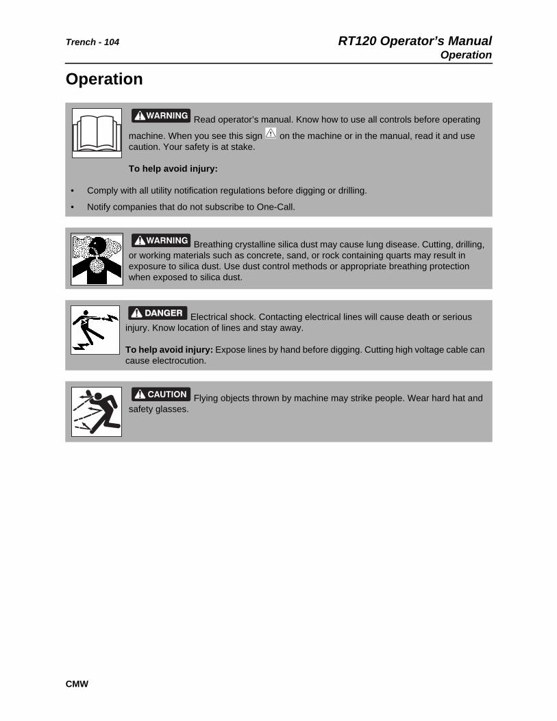
machine. When you see this sign on the machine or in the manual, read it and use caution. Your safety is at stake.
To help avoid injury:
• Comply with all utility notification regulations before digging or drilling.
• Notify companies that do not subscribe to One-Call.
Breathing crystalline silica dust may cause lung disease. Cutting, drilling, or working materials such as concrete, sand, or rock containing quarts may result in exposure to silica dust. Use dust control methods or appropriate breathing protection when exposed to silica dust.
Electrical shock. Contacting electrical lines will cause death or serious injury. Know location of lines and stay away.
To help avoid injury: Expose lines by hand before digging. Cutting high voltage cable can cause electrocution.
Flying objects thrown by machine may strike people. Wear hard hat and safety glasses.

RT120 Operator’s Manual Trench - 105Operation
CMW
Start Trench
1. Lower backfill blade, if equipped, to reduce shock when trenching begins.
2. If equipped with combo, set trench/plow switch to the trench position.
3. Move attachment speed/direction control to desired speed. DIGGING CHAIN WILL MOVE.
4. Set throttle to full engine speed.
5. Lift trench cleaner, if equipped.
6. Slowly lower digging boom to desired trench depth.
Moving digging teeth will cause death or serious injury. Stay away.
To help avoid injury:
• Machine might jerk when digging starts. Allow 3’ (1 m) between digging teeth and obstacle.
• Keep everyone at least 6’ (2 m) from machine, attachments, and their range of movement.

Trench - 106 RT120 Operator’s ManualOperation
CMW
Move Forward
1. Raise backfill blade, if equipped.
2. Release parking brake, if set, and verify parking brake indicator is off.
3. If using trench cleaner:
• Use ground drive foot control to move forward about 1 foot (30 cm), or until there is enough room for trench cleaner to enter trench.
• Return ground drive control to neutral to stop forward movement.
• Raise boom slightly, then fully lower trench cleaner to lock it in place.
• Lower boom to desired trench depth.
4. Move ground drive hand control to desired speed. Always start trenching with ground drive gear selector in position 1 and motor speed switch in low.
5. Increase ground drive speed only as soil conditions permit.
6. Operate engine at full throttle when working.
NOTICE:
• Do not have trench cleaner in working position when starting a trench.
• Do not back up with trench cleaner in working position.
• Do not use trench cleaner in working position in conditions where large rocks can get between chain and cleaner.
IMPORTANT:
• Ground drive speed/direction can be controlled with foot pedal or hand lever. When trenching, set ground drive speed with hand lever. Use foot pedal to temporarily adjust speed if digging conditions change for a short distance.
• For cruise control operation, see page 138.
NOTICE:
• Do not make sharp turns. Lower boom to full depth when turning.
• If an object becomes lodged in chain, move attachment speed/direction control to neutral and raise boom slightly. Reverse chain direction. If object must be removed manually, turn engine off and engage parking brake.
RT120 Operator’s Manual Trench - 107Operation
CMW
Finish Trenching
1. When trench is complete, move ground drive hand control to neutral.
2. Adjust throttle to low idle.
3. Raise boom.
4. As boom clears top of trench, move attachment speed/direction control to neutral.
5. Raise trench cleaner.
6. Swivel seat to the drive position.
7. Disengage axle lock.
8. Drive a short distance away from work site. See page 86 for driving procedures.
9. Shut down tractor. See page 88 for proper shutdown procedures.
10. Stow trench cleaner.
IMPORTANT: Drive tractor in reverse 6’ (2 m) while turning steering wheel left to right to fully disengage axle lock.

Trench - 108 RT120 Operator’s ManualOperation
CMW
RT120 Operator’s Manual Plow - 109
CMW
Plow
Chapter Contents
Setup . . . . . . . . . . . . . . . . . . . . . . . . . . . . . . . . . . . 110
• Position Tractor . . . . . . . . . . . . . . . . . . . . . . . . . . . . . . . . . . . . . . . . . . 111
• Attach Product. . . . . . . . . . . . . . . . . . . . . . . . . . . . . . . . . . . . . . . . . . . 111
Operation . . . . . . . . . . . . . . . . . . . . . . . . . . . . . . . . 113
• Special Plowing. . . . . . . . . . . . . . . . . . . . . . . . . . . . . . . . . . . . . . . . . . 117

Plow - 110 RT120 Operator’s ManualSetup
CMW
Setup
EMERGENCY SHUTDOWN - Turn ignition switch to STOP.
Crushing weight could cause death or serious injury. Use proper procedures and equipment or stay away.
To help avoid injury: Keep everyone at least 6’ (2 m) from machine, attachments, and their range of movement.
Jobsite hazards could cause death or serious injury. Use correct equipment and work methods. Use and maintain proper safety equipment.
To help avoid injury: Comply with all utility notification regulations before digging or drilling.
Read operator’s manual. Know how to use all controls before operating
machine. When you see this sign on the machine or in the manual, read it and use caution. Your safety is at stake.
To help avoid injury: Use attachments or counterweights to make front and rear loads balance when all attachments are raised. Contact your Ditch Witch dealer about counterweighting for your equipment.
NOTICE:
• Do not operate vibrator unless plow is in the ground.
• The RT120 is programmed to operate with the original attachment (trencher or plow) configuration. If you change attachments, contact your Ditch Witch dealer to make sure the electronic programming is updated. If you change attachments without updating the electronic programming, your attachment may not function correctly.

RT120 Operator’s Manual Plow - 111Setup
CMW
Position Tractor
1. Fasten and adjust seat belt.
2. Start tractor. See page 84 for start-up procedures.
3. Drive to starting point. Move in line with planned trench.
4. Engage parking brake and verify parking brake indicator is on.
5. Lower backfill blade, if equipped.
6. If equipped with combo, set trench/plow switch to the plow position.
7. Lower plow to starting point of trench.
8. Turn ignition switch to STOP.
Attach Product
To Pull Product
1. Insert material into pulling grip.
2. Tape grip with duct tape.
IMPORTANT: If material must be at a constant depth, dig starting and target trenches.

Plow - 112 RT120 Operator’s ManualSetup
CMW
To Feed Product
1. Remove cable guide.
2. Feed cable through tube from top to bottom.
3. Replace cable guide and tighten fasteners.
4. Secure cable.
IMPORTANT: ROPS-attached cable guide should be a genuine Ditch Witch cable guide manufactured for this purpose.
CAUTION: Keep everyone away from material being installed.

RT120 Operator’s Manual Plow - 113Operation
CMW
Operation
Read operator’s manual. Know how to use all controls before operating
machine. When you see this sign on the machine or in the manual, read it and use caution. Your safety is at stake.
To help avoid injury:
• Comply with all utility notification regulations before digging or drilling.
• Notify companies that do not subscribe to One-Call.
Breathing crystalline silica dust may cause lung disease. Cutting, drilling, or working materials such as concrete, sand, or rock containing quarts may result in exposure to silica dust. Use dust control methods or appropriate breathing protection when exposed to silica dust.
Electrical shock. Contacting electrical lines will cause death or serious injury. Know location of lines and stay away.
To help avoid injury: Expose lines by hand before digging. Cutting high voltage cable can cause electrocution.
Crushing weight could cause death or serious injury. Use proper procedures and equipment or stay away.
NOTICE: Do not drive backward with plow in the ground.
Plow - 114 RT120 Operator’s ManualOperation
CMW
Prepare
1. Fasten and adjust seat belt.
2. Start tractor.
3. Adjust throttle to low idle.
4. Check that ground drive hand and foot controls are in neutral.
5. Release parking brake and verify parking brake indicator is off.
6. Move ground drive gear selector to position 1 and motor speed switch to low.
7. Lower reel carrier to lowest position possible, if equipped.
8. Raise backfill blade, if equipped.
9. Swivel seat to the desired position.
10. Engage axle lock.
NOTICE: Use extreme caution when operating reel carrier on sloped surfaces.

RT120 Operator’s Manual Plow - 115Operation
CMW
Lower Plow
1. If equipped with combo, ensure that the trench/plow switch is in the plow position.
2. Move ground drive hand control forward to plowing speed and lower plow blade into ground.
3. Move plow lift control to float.
4. Move plow swing control to float.
5. Increase engine speed to full throttle.
6. Move attachment speed/direction control forward to start plow vibration. PLOW WILL VIBRATE.
7. Reduce attachment speed to a point with the least tractor vibration and the highest ground drive speed possible without track slippage. Adjust vibrator speed if ROPS vibrates excessively.
8. Check cable for damage during plowing. Run continuity checks on electric cable and check pipe pressure. Damage can result from improper operation, incorrect blade choice, striking underground obstructions, or other conditions.
NOTICE:
• Lower plow into ground before moving plow lift control or plow swing control to float.
• Do NOT move ground drive to reverse with plow blade in the ground.
IMPORTANT: Keep sod cutter edge sharp when plowing in areas with heavy grass cover or surface clutter.
Note: In some soil conditions, changing vibrator weights can improve plow performance. Contact your Ditch Witch dealer for details.
Plow - 116 RT120 Operator’s ManualOperation
CMW
Finish Plowing
1. When installation is complete, move plow swing out of float.
2. With vibrator running, raise plow to ground level.
3. Move attachment speed/direction control to neutral.
4. Swivel seat to the drive position.
5. Engage parking brake and verify parking brake indicator is on.
6. Lower backfill blade, if equipped.
7. Turn ignition switch to STOP and remove product from plow.
8. Swing plow to center position and engage swing lock and stow lock.
9. Raise backfill blade, if equipped.
10. Disengage axle lock.
11. Drive a short distance away from work site.
12. Shut down tractor. See page 88 for proper shutdown procedures.
NOTICE: Do not operate vibrator when plow is out of the ground. This will cause excessive vibration resulting in rapid wear, and possible damage to the unit and product being installed.
IMPORTANT: Drive tractor in reverse 6’ (2 m) while turning steering wheel left to right to fully disengage axle lock.
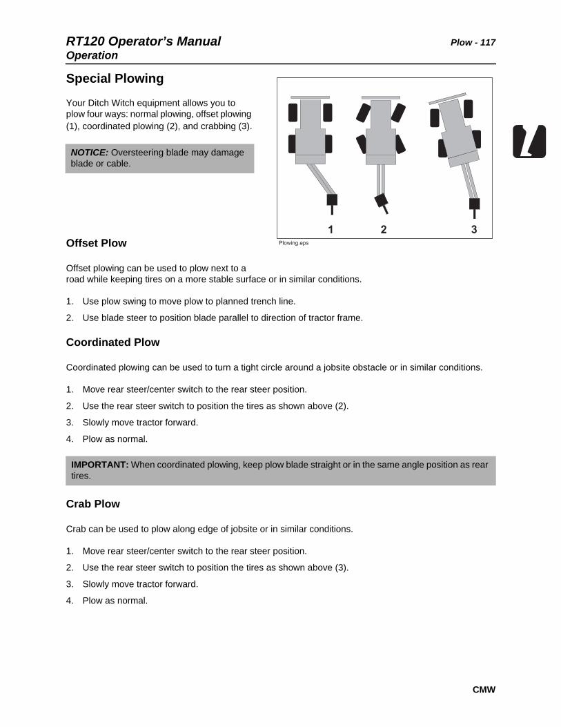
RT120 Operator’s Manual Plow - 117Operation
CMW
Special Plowing
Your Ditch Witch equipment allows you to plow four ways: normal plowing, offset plowing (1), coordinated plowing (2), and crabbing (3).
Offset Plow
Offset plowing can be used to plow next to a road while keeping tires on a more stable surface or in similar conditions.
1. Use plow swing to move plow to planned trench line.
2. Use blade steer to position blade parallel to direction of tractor frame.
Coordinated Plow
Coordinated plowing can be used to turn a tight circle around a jobsite obstacle or in similar conditions.
1. Move rear steer/center switch to the rear steer position.
2. Use the rear steer switch to position the tires as shown above (2).
3. Slowly move tractor forward.
4. Plow as normal.
Crab Plow
Crab can be used to plow along edge of jobsite or in similar conditions.
1. Move rear steer/center switch to the rear steer position.
2. Use the rear steer switch to position the tires as shown above (3).
3. Slowly move tractor forward.
4. Plow as normal.
NOTICE: Oversteering blade may damage blade or cable.
IMPORTANT: When coordinated plowing, keep plow blade straight or in the same angle position as rear tires.

Plow - 118 RT120 Operator’s ManualOperation
CMW

RT120 Operator’s Manual Reel Carrier - 119
CMW
Reel Carrier
Chapter Contents
Setup . . . . . . . . . . . . . . . . . . . . . . . . . . . . . . . . . . . 120
• Adjust Reel Winder . . . . . . . . . . . . . . . . . . . . . . . . . . . . . . . . . . . . . . . 120
Operation . . . . . . . . . . . . . . . . . . . . . . . . . . . . . . . . 122

Reel Carrier - 120 RT120 Operator’s ManualSetup
CMW
Setup
Adjust Reel Winder
1. Lower reel carrier.
2. Turn ignition switch to STOP.
3. Remove reel.
4. While supporting lever arm (3), remove bolt (1) that attaches hydraulic lift cylinder to lever arm.
5. Attach cylinder rod to the correct mounting hole for your diameter reel:
• For 2-5’ (61-152 cm) diameter reels, attach to bottom mounting hole (1).
• For 5-7’ (152-213 cm) diameter reels, attach to top mounting hole (2).
Read operator’s manual. Know how to use all controls before operating
machine. When you see this sign on the machine or in the manual, read it and use caution. Your safety is at stake.
Crushing weight could cause death or serious injury. Use proper procedures and equipment or stay away.

RT120 Operator’s Manual Reel Carrier - 121Setup
CMW
Reel Position
1. Install reel in one of two positions:
• P1
• P2
See “RC120 Reel Carrier” on page 213.
Ref. Maximum weight reel
Maximum length from blade
P1 2500 lb (1134 kg) 84 in (2.13 m)
P2 2200 lb (998 kg) 96 in (2.44 m)
t41om042w.eps
P1 P2

Reel Carrier - 122 RT120 Operator’s ManualOperation
CMW
Operation1. Fasten and adjust seat belt.
1. Drive to beginning of planned plow path.
2. Engage parking brake.
3. Lower backfill blade, if equipped.
4. Lower plow attachment.
5. Adjust throttle.
6. Attach service line to reel.
7. Move reel winder selector switch to activate reel winder control functions.
8. Lower reel winder arm until track meets reel flange.
9. Wind service line.
10. When finished winding, raise reel winder arm.
11. Adjust throttle.
12. Move reel winder selector switch to activate backfill blade controls.
13. Raise backfill blade, if equipped.
14. Release parking brake.
15. Follow directions in “Plow” on page 109 to begin plowing.
Moving parts could cut off hand or foot. Stay away.

RT120 Operator’s Manual Backhoe - 123
CMW
Backhoe
Chapter Contents
Setup . . . . . . . . . . . . . . . . . . . . . . . . . . . . . . . . . . . 124
Operation . . . . . . . . . . . . . . . . . . . . . . . . . . . . . . . . 125
Stowing . . . . . . . . . . . . . . . . . . . . . . . . . . . . . . . . . 126
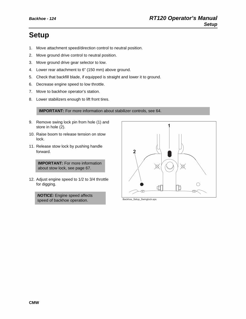
Backhoe - 124 RT120 Operator’s ManualSetup
CMW
Setup1. Move attachment speed/direction control to neutral position.
2. Move ground drive control to neutral position.
3. Move ground drive gear selector to low.
4. Lower rear attachment to 6” (150 mm) above ground.
5. Check that backfill blade, if equipped is straight and lower it to ground.
6. Decrease engine speed to low throttle.
7. Move to backhoe operator’s station.
8. Lower stabilizers enough to lift front tires.
9. Remove swing lock pin from hole (1) and store in hole (2).
10. Raise boom to release tension on stow lock.
11. Release stow lock by pushing handle forward.
12. Adjust engine speed to 1/2 to 3/4 throttle for digging.
IMPORTANT: For more information about stabilizer controls, see 64.
IMPORTANT: For more information about stow lock, see page 67.
NOTICE: Engine speed affects speed of backhoe operation.
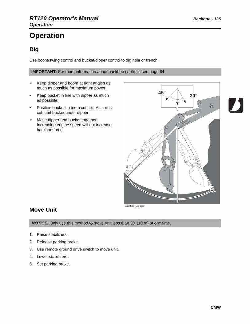
RT120 Operator’s Manual Backhoe - 125Operation
CMW
Operation
Dig
Use boom/swing control and bucket/dipper control to dig hole or trench.
• Keep dipper and boom at right angles as much as possible for maximum power.
• Keep bucket in line with dipper as much as possible.
• Position bucket so teeth cut soil. As soil is cut, curl bucket under dipper.
• Move dipper and bucket together. Increasing engine speed will not increase backhoe force.
Move Unit
1. Raise stabilizers.
2. Release parking brake.
3. Use remote ground drive switch to move unit.
4. Lower stabilizers.
5. Set parking brake.
IMPORTANT: For more information about backhoe controls, see page 64.
NOTICE: Only use this method to move unit less than 30’ (10 m) at one time.

Backhoe - 126 RT120 Operator’s ManualOperation
CMW
Stow
1. When hole or trench is complete, lift boom while keeping dipper pointed at ground.
2. Curl bucket closed and move dipper fully toward boom.
3. Lift boom to highest position and latch stow lock.
4. Lower boom slightly to engage lock.
5. Engage swing lock. See page 64.
NOTICE: Before returning to tractor operator station, raise stabilizers, return remote throttle to low idle, and stow and lock boom.
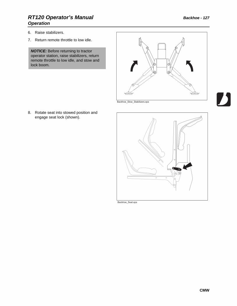
RT120 Operator’s Manual Backhoe - 127Operation
CMW
6. Raise stabilizers.
7. Return remote throttle to low idle.
8. Rotate seat into stowed position and engage seat lock (shown).
NOTICE: Before returning to tractor operator station, raise stabilizers, return remote throttle to low idle, and stow and lock boom.

Backhoe - 128 RT120 Operator’s ManualOperation
CMW
RT120 Operator’s Manual Drill - 129
CMW
Drill
Chapter Contents
Drilling Attachment. . . . . . . . . . . . . . . . . . . . . . . . 130
Prepare Jobsite and Equipment . . . . . . . . . . . . . 131
• Approach Trench. . . . . . . . . . . . . . . . . . . . . . . . . . . . . . . . . . . . . . . . . 131
• Target Trench . . . . . . . . . . . . . . . . . . . . . . . . . . . . . . . . . . . . . . . . . . . 131
• Drill Rod and Equipment . . . . . . . . . . . . . . . . . . . . . . . . . . . . . . . . . . . 132
Drill . . . . . . . . . . . . . . . . . . . . . . . . . . . . . . . . . . . . . 133
• Using Drill String Guide. . . . . . . . . . . . . . . . . . . . . . . . . . . . . . . . . . . . 134
Add Rod . . . . . . . . . . . . . . . . . . . . . . . . . . . . . . . . . 135
Backream. . . . . . . . . . . . . . . . . . . . . . . . . . . . . . . . 135
Disassemble Joints . . . . . . . . . . . . . . . . . . . . . . . 136

Drill - 130 RT120 Operator’s ManualDrilling Attachment
CMW
Drilling Attachment
Turning shaft will kill you or crush arm or leg. Stay away.
To help avoid injury:
• Do not straddle trench or drill pipe while drilling. Keep everybody at least 10’ (3 m) away from drill pipe during operation.
• Keep all persons away from material being installed. If swivel malfunctions, material being installed can rotate.
• Use a guide to align drill rod when starting a bore. Guides are available from your Ditch Witch dealership.
Jobsite hazards could cause death or serious injury. Use correct equipment and work methods. Use and maintain proper safety equipment.
To help avoid injury: Set up warning barriers and keep people away from equipment and jobsite while drilling.
Read operator’s manual. Know how to use all controls before operating
machine. When you see this sign on the machine or in the manual, read it and use caution. Your safety is at stake.
Improper control function could cause death or serious injury. If control does not work as described in instructions, stop machine and have it serviced.
To help avoid injury:
• Do not alter controls. Improper control function can cause serious injury.
• Do not tape or tie down switch or lever.
• Stop drilling and turn off power supply if releasing control does not stop turning shaft. Have unit repaired.

RT120 Operator’s Manual Drill - 131Prepare Jobsite and Equipment
CMW
Prepare Jobsite and Equipment
Approach Trench (1)
1. Mark path where you intend to drill.
2. Dig an approach trench (1) along the intended bore path.
Target Trench (2)
1. Select a completion point for the drilling project.
2. Dig a target trench (2) across the anticipated completion point.
IMPORTANT: The approach trench should be at least:
• deep enough for pipe to lay flat and enter soil at correct angle
• 20’ (6 m) long
• 4” (100 mm) wide
IMPORTANT:
• The actual length of the target trench depends on soil conditions and length of pipe sections. Make it deep enough for drill bit to enter slightly above the trench floor.
• An alternative to digging a target trench is to use an electronic tracker to locate the bit, then dig down with posthole diggers. This method may be desirable to minimize surface soil disturbance.

Drill - 132 RT120 Operator’s ManualPrepare Jobsite and Equipment
CMW
Drill Rod and Equipment
1. Assemble at least 20’ (6 m), but not more than 30’ (9 m), of drill rod.
2. Install drill bit to the cutting end of the drill string.
3. Put drill string in approach trench.
4. Move tractor to the approach trench and align the drilling attachment with the intended bore path.
5. Turn off engine.
6. Attach drill string to drilling attachment.
NOTICE: More than 10-15’ (3-4.5 m) of drill rod out of the trench increases the tendency of drill rod to bend.

RT120 Operator’s Manual Drill - 133Drill
CMW
Drill
1. Start tractor’s engine and begin clockwise (forward) rotation.
2. Slowly advance tractor while maintaining clockwise rotation.
EMERGENCY SHUTDOWN: Release drilling control and turn ignition switch to STOP.
NOTICE:
• Drilling too quickly causes bit to drift off course and may bend drill rod. After bore path is established, speed may be slightly increased.
• If drill rod starts to bend, stop forward movement of unit and back the unit slightly until rod straightens. Do not drill with bent rod.
• If drill rod hits an obstruction, rotate drill string counterclockwise to back up slightly.

Drill - 134 RT120 Operator’s ManualDrill
CMW
Using Drill String Guide
Use drill string guide to align drill string as it enters the soil. When using drill string guide, follow these guidelines:
• Use only approved Ditch Witch drill string guide (p/n 179-737).
• Stand only on the left side of the approach trench.
• Keep drill string guide at least 3’ (1 m) behind bit.
• Use drill string guide to control only the first 5’ (1.5 m) of the bore path.
• After drilling 5’ (1.5 m), stop unit and remove drill string guide.
• Do not use drill string guide during backreaming or any time the drill string is being pulled back.
Turning shaft will kill you or crush arm or leg. Stay away.
To help avoid injury:
• Do not straddle trench or drill rod while drilling. Keep everybody at least 10’ (3 m) away from drill rod during operation.
• Use a drill string guide to align drill rod when starting a bore. Guides are available from your Ditch Witch dealership.

RT120 Operator’s Manual Drill - 135Add Rod
CMW
Add Rod
1. Use control to stop drilling attachment.
2. Use ground drive controls to back up unit 6” (150 mm) to loosen drill rod in ground.
3. Disconnect drill rod from drilling attachment.
4. Use ground drive controls to move unit away from bore.
5. Add one drill rod to continue bore.
• Have a helper direct unit operator to align drilling attachment with new rod and stop when drilling attachment and rod are 1” (25 mm) apart.
• Have a helper lightly hold rod and direct unit operator to move unit forward slowly.
• As soon as rod begins to engage drilling attachment, have helper release rod and move hands and arms clear of drilling attachment.
BackreamAfter drill bit enters target trench, the bore hole may be enlarged by changing the drill bit to a backreamer and drawing it back through the initial bore.
1. Turn tractor ignition switch to STOP.
2. Replace drill bit with backreamer.
3. Start tractor engine and begin clockwise rotation.
4. Slowly back up tractor while maintaining rotation.
5. When backreamer exits the bore hole, stop rotation immediately.
IMPORTANT: It is recommended that a helper be used to add drill rod.
NOTICE: Always rotate clockwise during backreaming. Rotate counterclockwise only to dislodge a dry bore bit or reamer that has seized in the bore hole.
NOTICE:
• Do not try to increase hole size too much in one pass. Several passes using successively larger reamers will save wear on machine.
• During backreaming, keep drill string straight. Sharp bends in the drill rod at the motor coupling can cause rod failure.

Drill - 136 RT120 Operator’s ManualDisassemble Joints
CMW
Disassemble Joints1. Press tab through hole in female side of
joint (1) using special tool or screwdriver.
2. Pull rods apart (2).

RT120 Operator’s Manual Saw - 137
CMW
Saw
Chapter Contents
Setup . . . . . . . . . . . . . . . . . . . . . . . . . . . . . . . . . . . 138
• Before First Use . . . . . . . . . . . . . . . . . . . . . . . . . . . . . . . . . . . . . . . . . 138
Operation . . . . . . . . . . . . . . . . . . . . . . . . . . . . . . . . 140
• Normal Use . . . . . . . . . . . . . . . . . . . . . . . . . . . . . . . . . . . . . . . . . . . . . 141
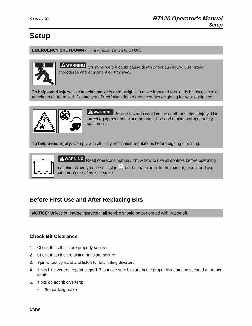
Saw - 138 RT120 Operator’s ManualSetup
CMW
Setup
Before First Use and After Replacing Bits
Check Bit Clearance
1. Check that all bits are properly secured.
2. Check that all bit retaining rings are secure.
3. Spin wheel by hand and listen for bits hitting diverters.
4. If bits hit diverters, repeat steps 1-3 to make sure bits are in the proper location and secured at proper depth.
5. If bits do not hit diverters:
• Set parking brake.
EMERGENCY SHUTDOWN - Turn ignition switch to STOP.
Crushing weight could cause death or serious injury. Use proper procedures and equipment or stay away.
To help avoid injury: Use attachments or counterweights to make front and rear loads balance when all attachments are raised. Contact your Ditch Witch dealer about counterweighting for your equipment.
Jobsite hazards could cause death or serious injury. Use correct equipment and work methods. Use and maintain proper safety equipment.
To help avoid injury: Comply with all utility notification regulations before digging or drilling.
Read operator’s manual. Know how to use all controls before operating
machine. When you see this sign on the machine or in the manual, read it and use caution. Your safety is at stake.
NOTICE: Unless otherwise instructed, all service should be performed with tractor off.

RT120 Operator’s Manual Saw - 139Setup
CMW
• Fasten and adjust seat belt.
• Start tractor and adjust throttle.
• Raise saw slightly.
• Use attachment speed/direction control to rotate saw slowly. As it rotates, listen for clicking sounds. If clicking is present, repeat steps 1-4.

Saw - 140 RT120 Operator’s ManualOperation
CMW
Operation
Breathing crystalline silica dust may cause lung disease. Cutting, drilling, or working materials such as concrete, sand, or rock containing quartz may result in exposure to silica dust. Use dust control methods or appropriate breathing protection when exposed to silica dust.
Electrical shock. Contacting electrical lines will cause death or serious injury. Know location of lines and stay away.
To help avoid injury: Expose lines by hand before digging. Cutting high voltage cable can cause electrocution.
Read operator’s manual. Know how to use all controls before operating
machine. When you see this sign on the machine or in the manual, read it and use caution. Your safety is at stake.
Flying objects thrown by machine may strike people. Wear hard hat and safety glasses.
Moving digging teeth will kill you or cut off arm or leg. Stay away.
To help avoid injury:
• Allow 3’ (1 m) between digging teeth and obstacle. Machine might jerk when digging starts.
• Keep everyone at least 6’ (2 m) from machine, attachments, and their range of movement.

RT120 Operator’s Manual Saw - 141
CMW
Normal Use
1. Fasten and adjust seat belt.
2. Start tractor. See page 84 for start-up procedures.
3. Drive to starting point. Move in line with planned trench. See page 78 for correct operating procedures.
4. Engage parking brake and verify parking brake indicator is on.
5. Move ground drive gear selector to position 1 and motor speed switch to low.
6. Tilt steering wheel column up.
7. Swivel seat to the desired position.
8. Engage axle lock.
9. Lower saw to just above ground.
10. Lower stabilizer until distance from bottom of skid shoe to bottom of saw bits equals desired trench depth.
11. Ensure that saw is aligned with planned trench and that tires are pointing straight ahead. Work slowly and carefully.
IMPORTANT:
• Saw use is not recommended for soft, wet, or sticky soil conditions.
• Before operating saw, check bits for free rotation. Tap bits lightly with a hammer and turn by hand. If bits are stuck, remove and clean packed soil from bit block.
• For best results, use retaining clip loading and removing tool and a knock-out bar included with saw to remove and reinsert bits.
• Carbide bits are recommended for cutting abrasive material, such as sandstone or frozen sands or gravels.

Saw - 142 RT120 Operator’s Manual
CMW
1. Adjust throttle to low idle.
2. Move attachment speed/direction control to desired speed. SAW WILL TURN.
3. Slowly lower saw to trench depth.
4. Release parking brake and verify parking brake indicator is off.
5. Increase engine speed to full throttle.
6. Push ground drive control forward to trenching speed.
7. If a curved trench must be cut, make a series of straight cuts.
8. When trench is complete, adjust throttle to low idle.
9. Raise saw and stabilizers.
10. As saw clears top of trench, move attachment speed/direction control to neutral.
11. Swivel seat to the drive position.
12. Tilt steering wheel column down.
13. Drive a short distance away from work site.
Moving digging teeth will kill you or cut off arm or leg. Stay away.
To help avoid injury:
• Machine might jerk when digging starts. Allow 3’ (1 m) between digging teeth and obstacle.
• Keep everyone at least 6’ (2 m) from machine, attachments, and their range of movement.
Read operator’s manual. Know how to use all controls before
operating machine. When you see this sign on the machine or in the manual, read it and use caution. Your safety is at stake.
To help avoid injury: Ensure that stabilizers are in contact with the ground while sawing. Failure to use stabilizers correctly will damage equipment.
IMPORTANT:
• Lower saw into softer material then move into harder or abrasive material. For example, lower saw into dirt at shoulder before cutting across road.
• For cruise control operation, see page 146.

RT120 Operator’s Manual Saw - 143
CMW
14. Disengage axle lock.
15. Shut down tractor. See “Shut Down” on page 88 for correct shutdown procedures.
16. Wash bits and mounting blocks with high pressure water before parking unit overnight.
IMPORTANT: Drive tractor in reverse 6’ (2 m) while turning steering wheel left to right to fully disengage axle lock.

Saw - 144 RT120 Operator’s Manual
CMW

RT120 Operator’s Manual Systems and Equipment - 145
Systems and Equipment
Chapter Contents
Cruise Control . . . . . . . . . . . . . . . . . . . . . . . . . . . . 146
• Operate Cruise Control . . . . . . . . . . . . . . . . . . . . . . . . . . . . . . . . . . . . 146
Chain, Teeth, and Sprockets . . . . . . . . . . . . . . . . 148
• Chain and Tooth Maintenance . . . . . . . . . . . . . . . . . . . . . . . . . . . . . . 148
• Chain Types . . . . . . . . . . . . . . . . . . . . . . . . . . . . . . . . . . . . . . . . . . . . 148
• Chain Selection . . . . . . . . . . . . . . . . . . . . . . . . . . . . . . . . . . . . . . . . . . 148
Optional Equipment . . . . . . . . . . . . . . . . . . . . . . . 150
• RT120 Tractor . . . . . . . . . . . . . . . . . . . . . . . . . . . . . . . . . . . . . . . . . . . 150
• H910/H911 Trencher. . . . . . . . . . . . . . . . . . . . . . . . . . . . . . . . . . . . . . 150
• H932 Plow. . . . . . . . . . . . . . . . . . . . . . . . . . . . . . . . . . . . . . . . . . . . . . 150
• H1140 Saw . . . . . . . . . . . . . . . . . . . . . . . . . . . . . . . . . . . . . . . . . . . . . 150
• A920 Backhoe. . . . . . . . . . . . . . . . . . . . . . . . . . . . . . . . . . . . . . . . . . . 150

Systems and Equipment - 146 RT120 Operator’s ManualCruise Control
Cruise ControlCruise control is a standard feature that allows the unit to automatically adjust ground drive speed according to digging conditions. In easier soil conditions, the ground drive speed will increase. When the unit encounters difficult soil conditions, the ground drive speed will decrease. The unit does this by adjusting ground drive pump output to maintain a preset engine speed.
Operate Cruise Control
Plowing
1. First set the following controls:
• ground drive controls to neutral
• ground drive switch to low
• ensure cruise control is off
• all other controls set as desired
2. Move ground drive gear selector to position 1.
3. Press cruise control switch once and ensure that cruise control indicator lights.
4. Use RPM control to select optimum engine speed for digging conditions.
5. When finished plowing, move ground drive control to neutral and press cruise control switch again to turn off cruise control.
EMERGENCY SHUTDOWN - Turn ignition switch to STOP.

RT120 Operator’s Manual Systems and Equipment - 147Cruise Control
Trenching
1. First set the following controls:
• ground drive controls to neutral
• ground drive switch to low
• ensure cruise control is off
• all other controls set as desired
2. Move ground drive gear selector to position 1.
3. Press cruise control switch once and ensure that cruise control indicator lights.
4. Following procedures on page 104, begin trenching to desired depth.
5. When desired depth is reached, ensure throttle is fully open.
6. Slowly move ground drive control forward.
7. Slowly adjust cruise control RPM control to match digging conditions.
8. When finished trenching, move ground drive control to neutral and press cruise control switch again to turn off cruise control.
9. Allow chain to dig itself free before stopping attachment.
IMPORTANT:
• In harder digging conditions, higher cruise control rpm setting may improve digging performance.
• In easier digging conditions, lower cruise control rpm setting may increase ground drive speed.
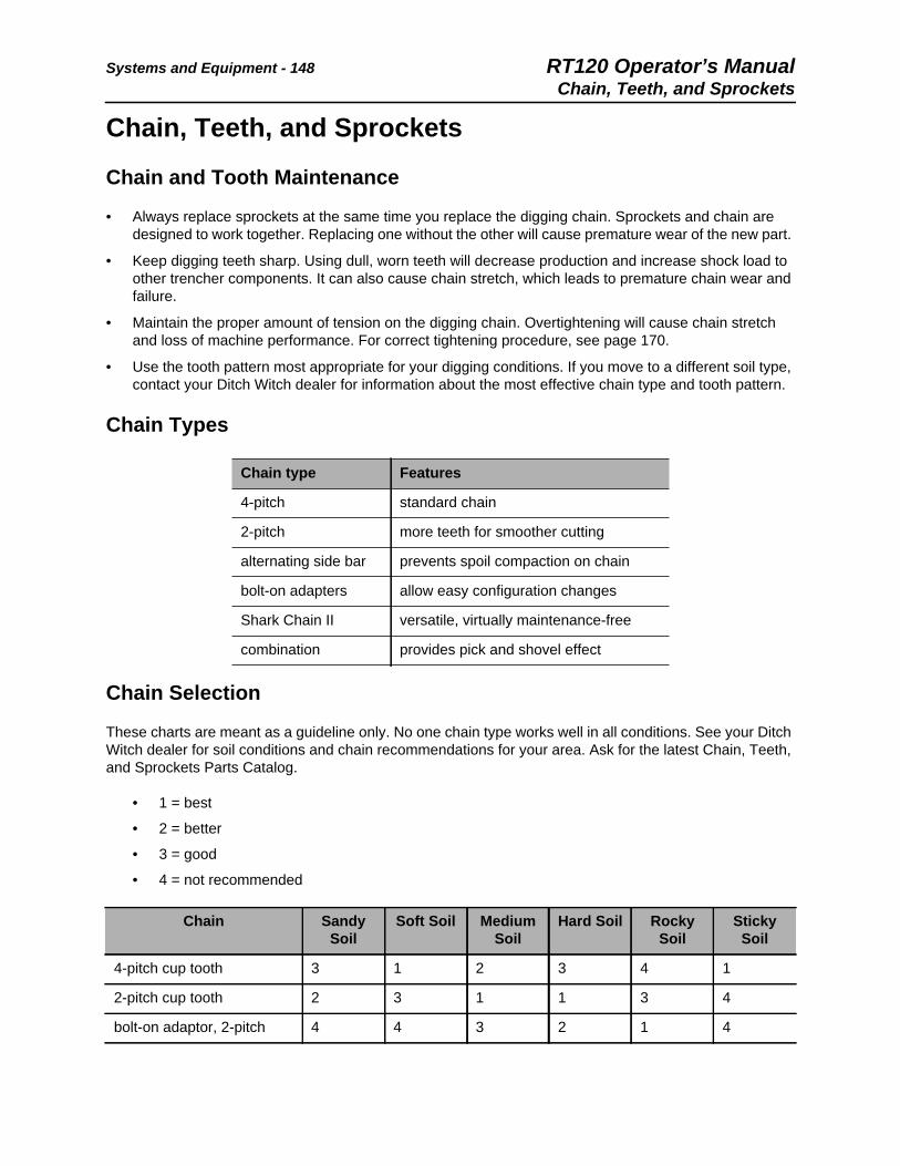
Systems and Equipment - 148 RT120 Operator’s ManualChain, Teeth, and Sprockets
Chain, Teeth, and Sprockets
Chain and Tooth Maintenance
• Always replace sprockets at the same time you replace the digging chain. Sprockets and chain are designed to work together. Replacing one without the other will cause premature wear of the new part.
• Keep digging teeth sharp. Using dull, worn teeth will decrease production and increase shock load to other trencher components. It can also cause chain stretch, which leads to premature chain wear and failure.
• Maintain the proper amount of tension on the digging chain. Overtightening will cause chain stretch and loss of machine performance. For correct tightening procedure, see page 170.
• Use the tooth pattern most appropriate for your digging conditions. If you move to a different soil type, contact your Ditch Witch dealer for information about the most effective chain type and tooth pattern.
Chain Types
Chain Selection
These charts are meant as a guideline only. No one chain type works well in all conditions. See your Ditch Witch dealer for soil conditions and chain recommendations for your area. Ask for the latest Chain, Teeth, and Sprockets Parts Catalog.
• 1 = best
• 2 = better
• 3 = good
• 4 = not recommended
Chain type Features
4-pitch standard chain
2-pitch more teeth for smoother cutting
alternating side bar prevents spoil compaction on chain
bolt-on adapters allow easy configuration changes
Shark Chain II versatile, virtually maintenance-free
combination provides pick and shovel effect
Chain Sandy Soil
Soft Soil Medium Soil
Hard Soil Rocky Soil
Sticky Soil
4-pitch cup tooth 3 1 2 3 4 1
2-pitch cup tooth 2 3 1 1 3 4
bolt-on adaptor, 2-pitch 4 4 3 2 1 4

RT120 Operator’s Manual Systems and Equipment - 149Chain, Teeth, and Sprockets
bolt-on adaptor/cup tooth combo
4 3 2 1 2 4
Shark Chain II 4 3 2 1 1 4
alternating side bar 4 4 4 4 4 1
Soil Description
sandy soil sugar sand, blow sand, or other soils where sand is the predominant component
soft soil sandy loam
medium soil loams, loamy clays
hard soil packed clays, gumbo, all compacted soils
rocky soil chunk rock, glacial till, cobble, rip rap, gravel
sticky soil gumbo, sticky clays
Chain Sandy Soil
Soft Soil Medium Soil
Hard Soil Rocky Soil
Sticky Soil
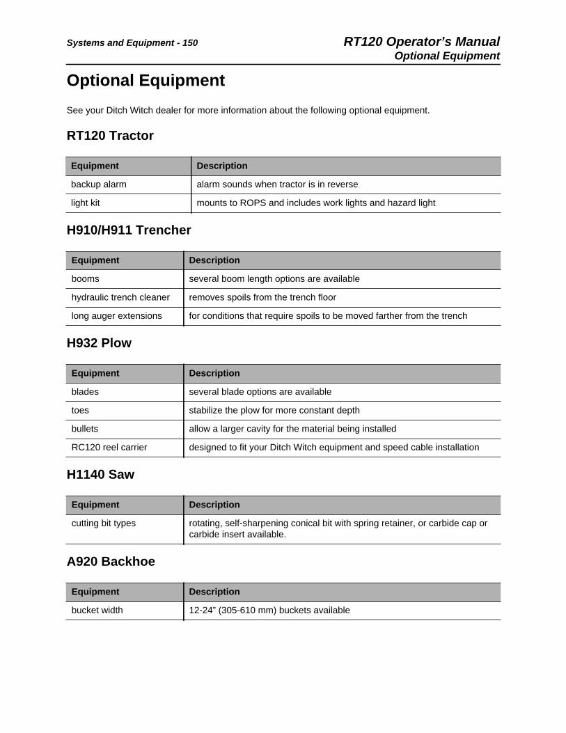
Systems and Equipment - 150 RT120 Operator’s ManualOptional Equipment
Optional EquipmentSee your Ditch Witch dealer for more information about the following optional equipment.
RT120 Tractor
H910/H911 Trencher
H932 Plow
H1140 Saw
A920 Backhoe
Equipment Description
backup alarm alarm sounds when tractor is in reverse
light kit mounts to ROPS and includes work lights and hazard light
Equipment Description
booms several boom length options are available
hydraulic trench cleaner removes spoils from the trench floor
long auger extensions for conditions that require spoils to be moved farther from the trench
Equipment Description
blades several blade options are available
toes stabilize the plow for more constant depth
bullets allow a larger cavity for the material being installed
RC120 reel carrier designed to fit your Ditch Witch equipment and speed cable installation
Equipment Description
cutting bit types rotating, self-sharpening conical bit with spring retainer, or carbide cap or carbide insert available.
Equipment Description
bucket width 12-24” (305-610 mm) buckets available

RT120 Operator’s Manual Complete the Job - 151
CMW
Complete the Job
Chapter Contents
Restore Jobsite . . . . . . . . . . . . . . . . . . . . . . . . . . . 152
• Backfilling . . . . . . . . . . . . . . . . . . . . . . . . . . . . . . . . . . . . . . . . . . . . . . 152
Rinse Equipment . . . . . . . . . . . . . . . . . . . . . . . . . 152
Stow Tools . . . . . . . . . . . . . . . . . . . . . . . . . . . . . . 152

Complete the Job - 152 RT120 Operator’s ManualRestore Jobsite
CMW
Restore JobsiteAfter product is installed, return spoils to the trench with optional backfill blade.
Backfilling
1. Position unit at end of trench, several feet from spoils. Aim tractor at outer edge of spoils.
2. Adjust backfill blade to fit land contour.
3. Move outer edge of spoils toward trench. Take two or more passes at spoils rather than moving all spoils at once.
4. Repeat on other side of trench, if necessary.
5. Engage float and make final pass over trench.
Rinse EquipmentSpray water onto equipment to remove dirt and mud.
Stow ToolsMake sure all tools and accessories are loaded and properly secured on trailer.
NOTICE: Do not spray water onto operator’s console. Electrical components could be damaged. Wipe down instead.

RT120 Operator’s Manual Service - 153
Service
Chapter Contents
Service Precautions . . . . . . . . . . . . . . . . . . . . . . . 154
Lubrication Overview . . . . . . . . . . . . . . . . . . . . . . 155
Tier 4i Engine . . . . . . . . . . . . . . . . . . . . . . . . . . . . 156
Recommended Lubricants/Service Key . . . . . . 157
• Approved Fuel. . . . . . . . . . . . . . . . . . . . . . . . . . . . . . . . . . . . . . . . . . . 159
• Approved Coolant . . . . . . . . . . . . . . . . . . . . . . . . . . . . . . . . . . . . . . . . 160
• Engine Oil Temperature Chart . . . . . . . . . . . . . . . . . . . . . . . . . . . . . . 160
10 Hour . . . . . . . . . . . . . . . . . . . . . . . . . . . . . . . . . 161
50 Hour . . . . . . . . . . . . . . . . . . . . . . . . . . . . . . . . . 173
100 Hour. . . . . . . . . . . . . . . . . . . . . . . . . . . . . . . . . 175
250 Hour . . . . . . . . . . . . . . . . . . . . . . . . . . . . . . . . 178
500 Hour . . . . . . . . . . . . . . . . . . . . . . . . . . . . . . . . 180
1000 Hour . . . . . . . . . . . . . . . . . . . . . . . . . . . . . . . 183
2000 Hour. . . . . . . . . . . . . . . . . . . . . . . . . . . . . . . . 185
As Needed . . . . . . . . . . . . . . . . . . . . . . . . . . . . . . 187

Service - 154 RT120 Operator’s ManualService Precautions
Service Precautions
Welding
Cleaning
Changing Attachments
The RT120 T4i is programmed to operate with the original attachment configuration. If you change attachments, contact your Ditch Witch dealer to make sure the electronic programming is updated. If you change attachments without updating the electronic programming, your attachment may not function correctly.
Read operator’s manual. Know how to use all controls before operating
machine. When you see this sign on the machine or in the manual, read it and use caution. Your safety is at stake.
To help avoid injury:
• Perform all service with the engine off unless otherwise instructed.
• Refer to engine manufacturer’s manual for engine maintenance instructions.
• Lower unstowed attachments to ground, before servicing equipment,
NOTICE: Welding can damage electronics.
• Disconnect battery at battery disconnect switch, if equipped, or disconnect battery cables before welding to prevent damage to battery. Do not turn off battery disconnect switch with engine running or alternator and other electronic devices may be damaged.
• Connect welder ground clamp close to welding point and make sure no electronic components are in the ground path.
• Always disconnect the ECU ground connection from the frame, harness connections to the ECU, and other electronic components prior to welding on machine or attachments.
NOTICE: When cleaning equipment, do not spray electrical components with water.

RT120 Operator’s Manual Service - 155Lubrication Overview
Lubrication Overview
t41om010w.eps2705525-1
CHECK LEVEL CHANGE FILTER
10 h50 h
100 h250 h500 h
1000 h

Service - 156 RT120 Operator’s ManualTier 4i Engine
Tier 4i EngineThe Deutz Tier 4i TCD 3.6 L4 engine uses a computer-controlled fuel management system, turbocharger with charge air cooling, and exhaust after treatment system (EAT). The engine and the corresponding EAT system are adapted to each other and linked by an appropriate electronic controller.
The diesel oxidation catalytic converter behind the cylinder head at the rear of the engine is a very recognizable feature. A crankcase breather is located on top of the left side of engine.
Diagnostic and maintenance work may only be carried out by authorized personnel using equipment approved by Deutz.
Deutz control units are equipped with self-diagnostics. Active and passive error codes are saved in the error memory. Active errors are displayed on the electronic display panel or error lamp (flash code) CAN bus. If error codes are recorded, call Product Support.
NOTICE: Diesel engines that are equipped with an exhaust after treatment system (EAT) may only be operated with an ultra low sulfur diesel fuel. See “Approved Fuel” on page 159.
RT120 Operator’s Manual Service - 157Recommended Lubricants/Service Key
Recommended Lubricants/Service Key
Item Description
Tier 4i
DEO
Diesel engine oil meeting or exceeding Deutz specification DQC III- LA.
NOTICE: Shipped from factory with API CJ-4 DEO meeting Deutz specification DQC II-LA. Change oil initially at 250 hours.
• Engine must use low sulfated ash, phosphorous, and sulfur (low SAPS) oil.
• See viscosity chart.
• If oils meeting only API CJ-4 or ACEA E6/E9 are used, service interval is reduced to 250 hours.
Tier 3
DEO
Diesel engine oil meeting or exceeding Deutz specification DQC III.
NOTICE: Shipped from factory with API CJ-4 DEO meeting Deutz specification DQC II- LA. Change oil initially at 100 hours if fuel sulphur content exceeds 500 ppm (500 mg/kg). Otherwise, initial oil change should be at 250 hours.
• See viscosity chart.
• If oils meeting only API CJ-4 or ACEA E7 are used, service interval is reduced to 250 hours.
MPG Multipurpose grease. Use polyurea based NLGI GC-LB Grade 1.5 or lithium based NLGI GC-LB Grade 2.
EPG Extreme pressure grease. Use polyurea based NLGI GC-LB Grade 1.5 or lithium based NLGI GC-LB Grade 2, with extreme pressure additives.
MPL Multipurpose gear oil meeting API service classification GL-5 (SAE 80W90)
THF Tractor hydraulic fluid, similar to Phillips 66 HG, Mobilfluid 423, Chevron Tractor Hydraulic Fluid, Texaco TDH Oil, or equivalent
DEAC Low silicate, fully formulated diesel engine antifreeze/coolant meeting ASTM D6210.
Check level of fluid or lubricant
Check condition
Filter
Change, replace.
Adjust, service, or test

Service - 158 RT120 Operator’s ManualRecommended Lubricants/Service Key
Proper lubrication and maintenance protects Ditch Witch equipment from damage and failure. Service intervals listed are for minimum requirements. In extreme conditions, service machine more frequently. Use only recommended lubricants. Fill to capacities listed in “Fluid Capacities” on page 200.
For more information on engine lubrication and maintenance, see your Deutz engine manual.
NOTICE:
• Use only genuine Ditch Witch parts, filters, approved lubricants, TJC, and approved coolants to maintain warranty.
• Use the “Service Record” on page 221 to record all required service to your machine.

RT120 Operator’s Manual Service - 159Recommended Lubricants/Service Key
Approved Fuel
Tier 4i Engine (U.S., Canada, EU, and Japan)
This engine is designed to run on diesel fuel. Use only high quality fuel meeting ASTM D975 No. 2D, EN590, or equivalent. At temperatures below 32°F (0°C) winter fuel blends are acceptable. See the engine operation manual for more information.
Biodiesel blends up to 5% (B5) are approved for use in this unit. The fuel used must meet the specifications for diesel fuel shown above. In certain markets, higher blends may be used if certain steps are taken. Extra attention is needed when using biodiesel, especially when operating in cold weather or storing fuel. Contact your Ditch Witch dealer or the engine manufacturer for more information.
Tier 3 Engine (Rest of World)
This engine is designed to run on diesel fuel. Use only high quality fuel meeting ASTM D975 No. 2D, EN590, or equivalent. At temperatures below 32°F (0°C) winter fuel blends are acceptable. See the engine operation manual for more information.
Biodiesel blends up to 5% (B5) are approved for use in this unit. The fuel used must meet the specifications for diesel fuel shown above. In certain markets, higher blends may be used if certain steps are taken. Extra attention is needed when using biodiesel, especially when operating in cold weather or storing fuel. Contact your Ditch Witch dealer or the engine manufacturer for more information.
Avoid static electricity when fueling. Ultra Low Sulfur Diesel (ULSD) poses a greater static ignition hazard than earlier diesel formulations. Avoid death or serious injury from fire or explosion. Consult with your fuel system supplier to ensure the delivery system is in compliance with fueling standards for proper grounding and bonding practices.
NOTICE: Use only Ultra Low Sulfur Diesel (less than 15 ppm (15 mg/kg) sulfur content) in this unit. Operating with higher sulfur content will damage the engine and after treatment device.
IMPORTANT: Worldwide, fuel sulfur regulations vary widely. Fuel used should always comply with local regulations. Prior to shipping, Tier 3 units were filled with API CJ-4 DEO. If operating fuel with sulfur content above 500 ppm (500 mg/kg), change oil initially at 100 hours.

Service - 160 RT120 Operator’s ManualRecommended Lubricants/Service Key
Approved Coolant
This unit was filled with John Deere Cool-Gard II coolant before shipment from factory. Add only John Deere Cool-Gard II (p/n 255-006) or any fully formulated, ethylene glycol based, low-silicate, heavy-duty diesel engine coolant meeting ASTM specification D6210.
Engine Oil Temperature Chart
NOTICE:
• Use only pre-diluted coolant or concentrated coolant mixed with distilled water. Do not use tap water.
• Do not use water or high-silicate automotive-type coolant. This will lead to engine damage or premature engine failure.
• Do not mix heavy-duty diesel engine coolant and automotive-type coolant. This will lead to coolant breakdown and engine damage.
t37om047w.eps
SAE 0W-30
SAE 0W-40
SAE 5W-30
SAE 5W-40
SAE 10W-30
SAE 10W-40
SAE 15W-40
SAE 20W-50
Temperature range anticipated before next oil change
RT120 Operator’s Manual Service - 16110 Hour
10 Hour
Location Task Notes
TRACTOR Check engine oil level DEO
Check air filter indicator and clean dust trap
Check hydraulic fluid level THF
Check hydraulic hoses
Check coolant level DEAC
Check radiator fins
Check tire pressure and lugnuts
TRENCHER Lube trencher tail roller EPG
Lube trencher pivot EPG
Lube trencher auger bearings EPG
Lube trencher auger shaft EPG
Check trencher auger bolts
Check digging chain teeth and bits
Check boom mounting bolts 250 ft•lb (339 N•m)
Check attachment mounting bolts 200 ft•lb (271 N•m)
Check restraint bar position
Check trench cleaner position (if equipped)
Check personnel restraint bar/trench cleaner bolts 350 ft•lb (475 N•m)
Check digging chain tension
PLOW Lube plow pivots EPG
Check plow vibrator oil level MPL
Check plow arm pins and bushings
Check plow connector pivots
Check attachment mounting bolts 200 ft•lb (271 N•m)

Service - 162 RT120 Operator’s Manual10 Hour
Tractor
Check Engine Oil Level
Check engine oil at dipstick (1) before operation and every 10 hours thereafter. Add DEO at fill (2) as necessary to keep oil level at highest line on dipstick.
Check Air Filter Indicator and Clean Dust Trap
Check air filter indicator (1) and clean dust trap every 10 hours. Red band indicates filter must be changed. Push button (2) to re-set indicator.
Wipe dust from trap every 10 hours.
NOTICE: Only open the air filter canister when air restriction is indicated. Change the elements, do not attempt to clean them.
• Compressed air or water may damage filter elements.
• Tapping filter elements to loosen dirt may damage the elements.
t41om011w.eps
1 2
t41om012w.eps
1
2
t41om013w.eps
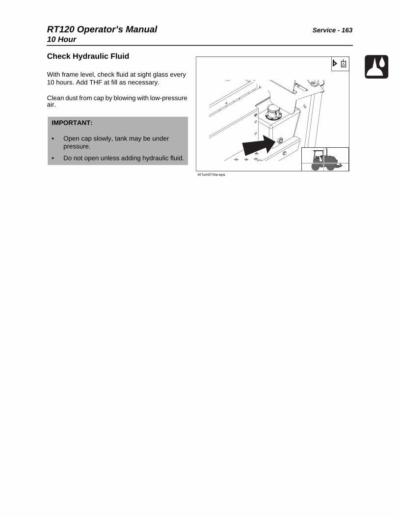
RT120 Operator’s Manual Service - 16310 Hour
Check Hydraulic Fluid
With frame level, check fluid at sight glass every 10 hours. Add THF at fill as necessary.
Clean dust from cap by blowing with low-pressure air.
IMPORTANT:
• Open cap slowly, tank may be under pressure.
• Do not open unless adding hydraulic fluid.
t41om014w.eps

Service - 164 RT120 Operator’s Manual10 Hour
Check Hydraulic Hoses
Check all hydraulic hoses every 10 hours.
Fluid or air pressure could pierce skin and cause injury or death. Stay away.
To help avoid injury:
• Before disconnecting a hydraulic line, turn engine off and operate all controls to relieve pressure. Lower, block, or support any raised component with a hoist. Cover connection with heavy cloth and loosen connector nut slightly to relieve residual pressure. Catch all fluid in a container.
• Before using system, check that all connections are tight and all lines are undamaged.
• Use a piece of cardboard or wood, rather than hands, to search for leaks.
• Wear protective clothing, including gloves and eye protection.
If you are injured, seek immediate medical attention from a doctor familiar with this type of injury.

RT120 Operator’s Manual Service - 16510 Hour
Check Coolant Level
With engine cool, check coolant level in expansion tank sight glass every 10 hours. Maintain level so that coolant is visible in sight glass and no higher than bottom of fill neck. If low, add approved coolant. Do not overfill. Add pre-diluted coolant to maintain proper freeze protection.
Check Radiator Fins
Check radiator for dirt, grass, and other foreign matter every 10 hours. Clean out with compressed air or spray wash if required. Be careful not to damage fins with high pressure air or water. Check more often if operating in dusty or grassy conditions.
Check Tire Pressure and Lugnuts
Check tire pressure every 10 hours.
Check tightness of wheel lugnuts (shown) every 10 hours. Tighten lugnuts to 295 ft•lb (400 N•m).
IMPORTANT: See page 160 for information on approved coolants.
Tire option Maximum pressure
38 x 18.00-20 16-ply 40 psi (2.8 bar)
t41om015w.eps
t41om016w.eps
Tires_Service.eps

Service - 166 RT120 Operator’s Manual10 Hour
Trencher
Lube Trencher Tail Roller
Wipe zerks clean and lube every 10 hours with EPG. Lube roller zerks on both sides of boom.
Lube Trencher Pivot
Wipe five zerks located on right of trencher pivot clean and lube every 10 hours with EPG.
Wipe four zerks located on left of trencher pivot clean and lube every 10 hours with EPG.
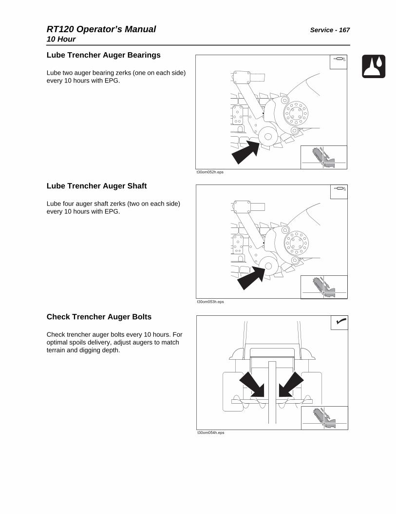
RT120 Operator’s Manual Service - 16710 Hour
Lube Trencher Auger Bearings
Lube two auger bearing zerks (one on each side) every 10 hours with EPG.
Lube Trencher Auger Shaft
Lube four auger shaft zerks (two on each side) every 10 hours with EPG.
Check Trencher Auger Bolts
Check trencher auger bolts every 10 hours. For optimal spoils delivery, adjust augers to match terrain and digging depth.

Service - 168 RT120 Operator’s Manual10 Hour
Check Digging Chain Teeth and Bits
Check teeth (1) for wear every 10 hours. Replace worn teeth, using Ditch Witch replacement parts and maintaining original tooth pattern.
For more efficient digging, contact your Ditch Witch dealer for information about the tooth pattern best suited to your jobsite.
If using rock chain bits, check that bits rotate freely. Clean chain and check bits after each use. Replace bit when carbide cap or insert is worn or adapter can be damaged.
Check chain every 10 hours. Replace worn or broken chains. If sidebars (2) are bent or loose on chain pins (3), chain spacers should be used to join sidebars.
Check Boom Mounting Bolts
Check 14 bolts (7 on each side) every 10 hours and tighten as necessary to keep bolts and other fasteners tight. Check for looseness or wear. Check that bolts are tightened to 250 ft•lb (28 N•m).

RT120 Operator’s Manual Service - 16910 Hour
Check Attachment Mounting Bolts
Check bolts every 10 hours and tighten as necessary to keep bolts and other fasteners tight. Check for looseness or wear. Apply Loctite 271® adhesive. Check that bolts are tightened to 200 ft•lb (271 N•m).
Check Restraint Bar Position
Check restraint bar position every 10 hours, or anytime the digging chain is adjusted or replaced. The restraint bar is properly positioned when the end of bar extends between the center of the tail roller/sprocket and the end of the digging chain. Check for looseness or wear.
Tighten bolts as necessary to keep them tight. Bolts mounting arm to boom should be tightened to 400 ft•lb (542 N•m). Apply Loctite 271® adhesive.
Check Trench Cleaner Position
Check trench cleaner position (if equipped) every 10 hours, or anytime the digging chain is adjusted or replaced. The trench cleaner is properly positioned when there is 3-4 in (76-102 mm) between the digging teeth and the inside of the trench cleaner shoe (A).
Check that bolts holding personnel restraint bar/trench cleaner to arm are tightened to 350 ft•lb (475 N•m). Apply Loctite 271® adhesive.
t33om89w.eps
AA
t33om90w.eps

Service - 170 RT120 Operator’s Manual10 Hour
Check Personnel Restraint Bar/Trench Cleaner Bolts
Check all bolts that mount restraint bar/trench cleaner to arm every 10 hours and tighten as necessary to keep bolts tight. Check for looseness or wear. Apply Loctite 271® adhesive.
Check that bolts holding personnel restraint bar/trench cleaner to arm are tightened to 350 ft•lb (475 N•m). Bolts mounting arm to boom should be tightened to 400 ft•lb (542 N•m).
Check Digging Chain Tension.
Check digging chain tension every 10 hours. With boom horizontal, measure distance from bottom of boom to chain. When properly adjusted, distance should be 4.5 - 5.5” (114 - 140 mm).
To tighten chain, loosen six bolts on trencher boom and pump EPG into cylinder. To relieve chain tension, loosen plug on grease cylinder.
Fluid pressure could pierce skin and cause injury or death. Stay away.
To help avoid injury: Service digging boom grease cylinder only while standing on opposite side of boom. Wear gloves and safety glasses, and cover fitting with cloth when relieving pressure in cylinder.

RT120 Operator’s Manual Service - 17110 Hour
Plow
Lube Plow Pivots
Lube pivots every 10 hours with EPG.
Check Plow Vibrator Oil Level
Check plow vibrator oil on each side of vibrator every 10 hours. With vibrator horizontal, oil should be halfway up sight glass (2). Add MPL as needed at fill (1).
Hot parts may cause burns. Do not touch until cool.

Service - 172 RT120 Operator’s Manual10 Hour
Check Plow Arm Pins and Bushings
Check plow arm pins and bushings every 10 hours. Tighten as needed.
Check Plow Connector Pivots
Visually check pivots every 10 hours for wear or damage.
Check Attachment Mounting Bolts
Check mounting bolts every 10 hours and tighten as necessary to keep bolts and other fasteners tight. Check for looseness or wear. Apply Loctite 271® adhesive. Check that bolts are tightened to 200 ft•lb (271 N•m).
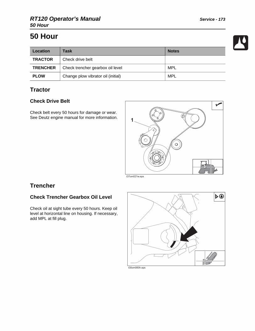
RT120 Operator’s Manual Service - 17350 Hour
50 Hour
Tractor
Check Drive Belt
Check belt every 50 hours for damage or wear. See Deutz engine manual for more information.
Trencher
Check Trencher Gearbox Oil Level
Check oil at sight tube every 50 hours. Keep oil level at horizontal line on housing. If necessary, add MPL at fill plug.
Location Task Notes
TRACTOR Check drive belt
TRENCHER Check trencher gearbox oil level MPL
PLOW Change plow vibrator oil (initial) MPL
t37om021w.eps
1
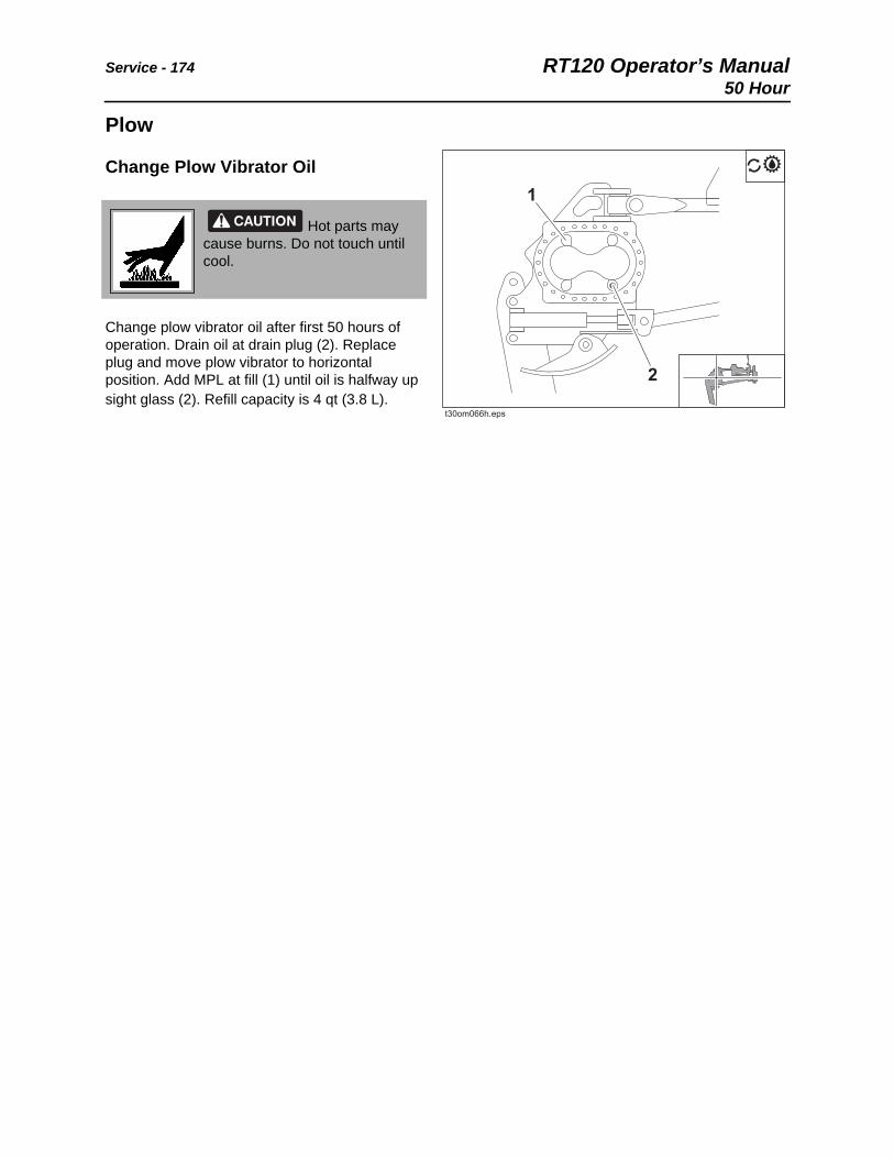
Service - 174 RT120 Operator’s Manual50 Hour
Plow
Change Plow Vibrator Oil
Change plow vibrator oil after first 50 hours of operation. Drain oil at drain plug (2). Replace plug and move plow vibrator to horizontal position. Add MPL at fill (1) until oil is halfway up sight glass (2). Refill capacity is 4 qt (3.8 L).
Hot parts may cause burns. Do not touch until cool.

RT120 Operator’s Manual Service - 175100 Hour
100 Hour
Tractor
Change Engine Oil and Filter (Initial)
Change engine oil and filter at 100 hours if fuel sulfur content is above 500 ppm (500 mg/kg). See page 157 for more information about DEO specifications.
To change:
1. While oil is warm, remove drain plug (3). Drain oil and replace plug.
2. Remove filter (1) and replace with new filter each time oil is changed. Add DEO at fill neck (2).
Location Task Notes
TRACTOR Change engine oil (Tier 3) Initial; if using fuel with sulfur content above 500 ppm (500 mg/kg)
Lube axle mounts EPG
Lube driveshaft U-joints EPG
Lube king pins EPG
PLOW Check plow shear mounts
Test plow connector pivots
13
2
t41om018w.eps

Service - 176 RT120 Operator’s Manual100 Hour
Lube Axle Mounts
Lube axle mount pivots every 100 hours with EPG.
Lube U-Joints
Lube driveshaft U-joints every 100 hours with EPG.
Lube King Pins
Lube king pins every 100 hours with EPG.
t41om019w.eps
t41om021w.eps
t41om020w.eps

RT120 Operator’s Manual Service - 177100 Hour
Plow
Check Shear Mounts
Check shear mounts for wear every 100 hours. Replace as needed.
Test Plow Connector Pivots
Test upper and lower connector pivots every 100 hours.
To test upper pivot:
1. Lower plow to ground.
2. Use plow lift control to put hydraulic load on pivot joints. Do not raise plow.
3. As hydraulic load is applied and released, visually check joints for motion. If motion is observed, contact your Ditch Witch dealer.
To test lower pivot:
1. Lower plow to ground.
2. Use hydraulic jack to place load on lower arm.
3. As hydraulic load is applied and released, visually check joints for motion. If motion is observed, contact your Ditch Witch dealer.
IMPORTANT: When replacing shear mounts, it is important to compress the shear mounts with the washers to prevent the shear mount from tearing.
IMPORTANT: Lower plow blade to ground and visually inspect bushings and joints. Replace bushings if there is excessive motion.

Service - 178 RT120 Operator’s Manual250 Hour
250 Hour
Tractor
Engine Oil and Filter Change (Tier 3)
Change engine oil and filter every 250 hours when using motor oils meeting only API CJ-4 or ACEA E7. See page 157 for more information about DEO specifications.
To change:
1. While oil is warm, remove drain plug (3). Drain oil and replace plug.
2. Remove filter (1) and replace with new filter each time oil is changed. Add DEO at fill neck (2).
Engine Oil and Filter Change (Tier 4i)
Change engine oil and filter every 250 hours when using motor oils meeting only API CJ-4 or ACEA E6/E9. See page 157 for more information about DEO specifications.
To change:
1. While oil is warm, remove drain plug (3). Drain oil and replace plug.
2. Remove filter (1) and replace with new filter each time oil is changed. Add DEO at fill neck (2).
Location Task Notes
TRACTOR Engine oil and filter change DEO
Check ground drive gearbox oil level MPL
Check differential oil level MPL
Lube planetary wheel ends MPL
13
2
t41om018w.eps
13
2
t41om018w.eps

RT120 Operator’s Manual Service - 179250 Hour
Check Ground Drive Gearbox Oil Level
Check oil level at fill (shown) every 250 hours. Keep level at raised horizontal line on gearbox. Add MPL as needed.
Check Differential Oil Level
Check oil level at fill (shown) every 250 hours. Add MPL as needed.
Check Planetary Wheel End Oil Level
Check oil level in planetary wheel ends every 250 hours. Add MPL as needed.
t41om022w.eps
t41om023w.eps
t41om024w.eps
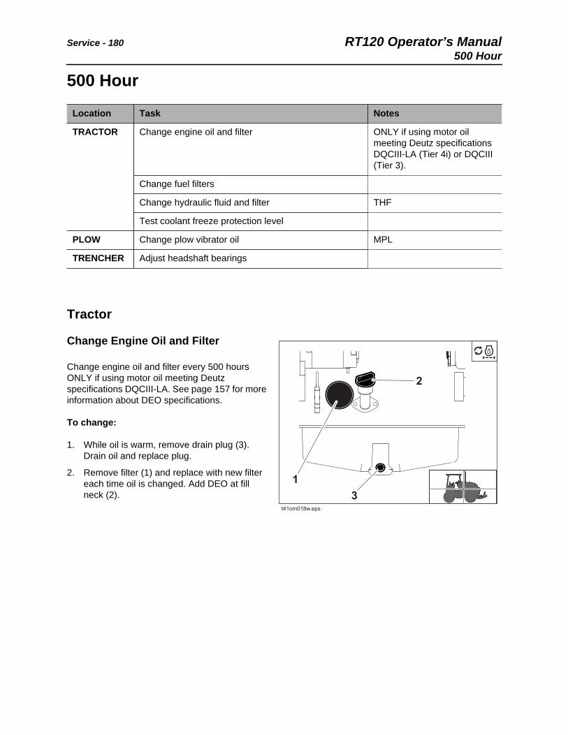
Service - 180 RT120 Operator’s Manual500 Hour
500 Hour
Tractor
Change Engine Oil and Filter
Change engine oil and filter every 500 hours ONLY if using motor oil meeting Deutz specifications DQCIII-LA. See page 157 for more information about DEO specifications.
To change:
1. While oil is warm, remove drain plug (3). Drain oil and replace plug.
2. Remove filter (1) and replace with new filter each time oil is changed. Add DEO at fill neck (2).
Location Task Notes
TRACTOR Change engine oil and filter ONLY if using motor oil meeting Deutz specifications DQCIII-LA (Tier 4i) or DQCIII (Tier 3).
Change fuel filters
Change hydraulic fluid and filter THF
Test coolant freeze protection level
PLOW Change plow vibrator oil MPL
TRENCHER Adjust headshaft bearings
13
2
t41om018w.eps

RT120 Operator’s Manual Service - 181500 Hour
Change Fuel Filters
Change fuel filters (shown) every 500 hours.
Change Hydraulic Fluid and Filter
Change hydraulic fluid and filter every 500 hours.
Change hydraulic fluid and filter every 250 hours if jobsite temperature exceeds 100°F (38°C) more than 50% of the time.
To change:
1. Remove drain plug (1).
2. Drain fluid and replace plug.
3. Change filter (2).
4. Add THF at fill (3).
Test Coolant Freeze Protection Level
With engine cool, test coolant freeze protection level using a hydrometer or refractometer. Recommended freeze protection level is -34°F (-37°C). Adjust as needed.
If colder temperatures are expected, consult your Ditch witch dealer or coolant supplier.
Use pre-diluted coolant to maintain proper freeze protection.
IMPORTANT: See page 160 for information on approved coolants.
t41om025w.eps
1
2
3
t41om026w.eps
t41om015w.eps

Service - 182 RT120 Operator’s Manual500 Hour
Plow
Change Plow Vibrator Oil
Change plow vibrator oil every 500 hours. If normal operating temperature exceeds 100°F (38°C), change plow vibrator oil every 250 hours.
Drain oil at drain plug (2). Replace plug and move plow vibrator to horizontal position. Add MPL at fill until oil is halfway up sight glass (1). Refill capacity is 4 qts (3.8 L).
Trencher
Adjust Headshaft Bearing
Adjust headshaft bearing every 500 hours.
To adjust:
1. Remove cover. Remove bolts attaching trenching attachment motor to gearbox.
2. Remove bolt and washers in left end of headshaft.
3. Support gearbox with hoist and slide it off headshaft.
4. Install spacer (p/n 184-044) in place of gearbox while checking bearings.
5. Replace bolt on end of headshaft.
6. Remove chain from headshaft sprocket.
7. Turn chain sprocket until headshaft sprocket turns. When properly adjusted, it will take two hands and some effort. If it turns easily, remove a shim.
Hot parts may cause burns. Do not touch until cool.

RT120 Operator’s Manual Service - 1831000 Hour
1000 Hour
Tractor
Change Differential Oil
Change differential oil every 1000 hours.
To change:
1. Remove drain plug (2).
2. Drain fluid and replace plug.
3. Add MPL at fill (1).
Change Ground Drive Gearbox Oil
Change ground drive gearbox oil every 1000 hours.
To change:
1. Remove drain plug (2).
2. Drain oil and replace plug.
3. Fill gearbox with MPL at fill (1).
Location Task Notes
TRACTOR Change differential oil MPL
Change ground drive gearbox oil MPL
Change planetary wheel end oil MPL
TRENCHER Change trencher gearbox oil MPL
t41om027w.eps
1
2t41om028w.eps

Service - 184 RT120 Operator’s Manual1000 Hour
Change Planetary Wheel End Oil
Change wheel end oil every 1000 hours.
To change:
1. Position wheel with plug at bottom.
2. Remove plug.
3. Drain oil.
4. Reposition wheel with plug at midway position.
5. Fill with MPL to plug opening.
6. Replace plug.
Trencher
Change Trencher Gearbox Oil
Change trencher gearbox oil every 1000 hours. Drain at plug. Replace drain plug and fill with MPL to lowest line on sight tube.
t41om029w.eps

RT120 Operator’s Manual Service - 1852000 Hour
2000 Hour
Tractor
Change Engine Coolant
Drain cooling system at drain (2) every two years or 2000 hours. Add approved coolant at fill (1).
Location Task Notes
TRACTOR Change engine coolant DEAC
Check seatbelt and seatbelt mounting hardware
NOTICE:
• The use of non-approved coolant may lead to engine damage or premature engine failure and will void engine warranty.
• See “Approved Coolant” on page 160 for list of approved coolants.
1
2
t41om030w.eps
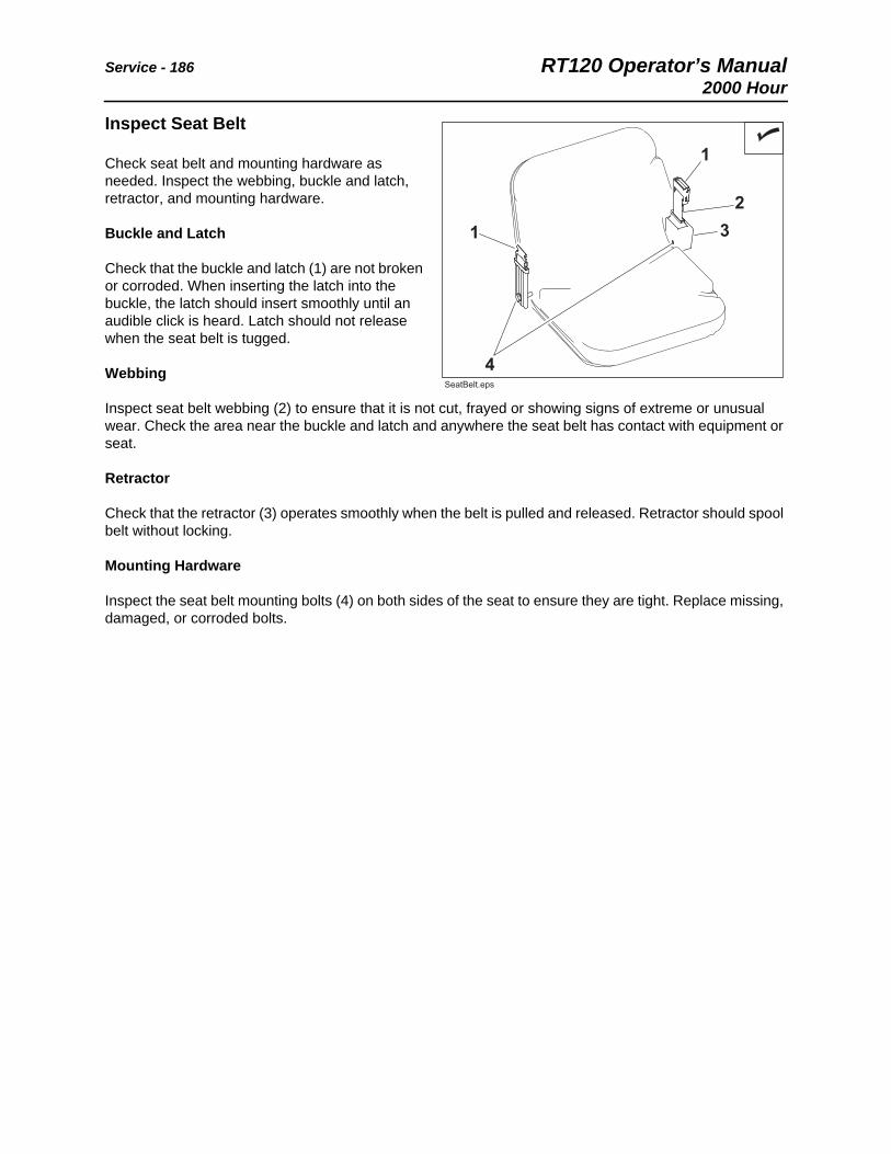
Service - 186 RT120 Operator’s Manual2000 Hour
Inspect Seat Belt
Check seat belt and mounting hardware as needed. Inspect the webbing, buckle and latch, retractor, and mounting hardware.
Buckle and Latch
Check that the buckle and latch (1) are not broken or corroded. When inserting the latch into the buckle, the latch should insert smoothly until an audible click is heard. Latch should not release when the seat belt is tugged.
Webbing
Inspect seat belt webbing (2) to ensure that it is not cut, frayed or showing signs of extreme or unusual wear. Check the area near the buckle and latch and anywhere the seat belt has contact with equipment or seat.
Retractor
Check that the retractor (3) operates smoothly when the belt is pulled and released. Retractor should spool belt without locking.
Mounting Hardware
Inspect the seat belt mounting bolts (4) on both sides of the seat to ensure they are tight. Replace missing, damaged, or corroded bolts.
22
11
11 33
44
SeatBelt.epsSeatBelt.eps
RT120 Operator’s Manual Service - 187As Needed
As Needed
Location Task Notes
TRACTOR Adjust parking brake
Clean radiator fins
Drain water separators and fuel filter As indicated on dash display
Check battery
Charge battery
TRENCHER Replace digging chain
PLOW Clean feed tube
Replace sod cutter and blade
Check plow blade bolts 210 ft•lb (285 N•m)
BACKHOE Replace pins and bushings

Service - 188 RT120 Operator’s ManualAs Needed
Tractor
Adjust Parking Brake
Adjust parking brake as needed.
To adjust:
1. Release parking brake.
2. Remove orange sleeve.
3. Twist lever clockwise to tighten.
4. Engage parking brake to test tension. If tension is too tight, the brake lever will not engage fully. Repeat steps 1-3 as necessary.
5. Replace orange sleeve.
Clean Radiator Fins
Clean out radiator fins with compressed air or spray wash if required. Be careful not to damage fins with high-pressure air or water. Check more often if operating in dusty or grassy conditions.
Drain Water Separators and Fuel Filter
Drain water separators and fuel filter as needed. WIF (water in fuel) indicator will indicate need.
Drain at plug as needed until water is removed and fuel runs from drain.
t41om031w.eps
t41om032w.eps
t41om033w.eps

RT120 Operator’s Manual Service - 189As Needed
Check Batteries
Check batteries as needed. Keep batteries clean and terminals free of corrosion.
To clean:
1. Turn battery disconnect switch, if equipped, to the off position.
2. Ensure that no ignition sources are near batteries.
3. Loosen and remove battery cable clamps carefully, negative (-) cable first.
4. Clean cable clamps and terminals to remove dull glaze.
5. Check for signs of internal corrosion in cables.
6. Apply MPG to terminals after cleaning to reduce corrosion.
7. Connect battery cable clamps, positive (+) cable first.
8. Tighten any loose connections.
9. Ensure that battery tiedowns are secure.
10. Turn battery disconnect switch to the on position.
Explosion possible. Serious injury or equipment damage could occur. Follow directions carefully.
To help avoid injury: Do not create sparks and do not short across battery terminals for any reason.
j37om035h.epsj37om035h.eps
Service - 190 RT120 Operator’s ManualAs Needed
Charge Battery
Before You Start
Electronic components can be easily damaged by electrical surges. Jump starting can damage electronics and electrical systems, and is not recommended. Try to charge the battery instead. Use quality large diameter booster cables capable of carrying high currents (400 amps or more). Cheap cables may not allow enough current flow to charge a dead/discharged battery.
Read all steps thoroughly and review illustration before performing procedure.
Explosion possible. Serious injury or equipment damage could occur. Follow directions carefully.
To help avoid injury:
• Use a single 12V maximum source for charging. Do not connect to rapid chargers or dual batteries.
• Use caution and wear personal protective equipment such as safety eyewear, when charging or cleaning battery.
• Keep sparks, flames, and any ignition source away from batteries at all times. Internal contents are extremely hazardous. Leaking fluid is corrosive. Battery may be explosive at higher temperatures.
• NEVER lean over battery when making connections.
• Do not allow vehicles to touch when charging.
• Do not attempt to charge a battery that is leaking, bulging, heavily corroded, frozen, or otherwise damaged.
• NEVER short-circuit battery terminals for any reason or strike battery posts or cable terminals.
• Refer to MSDS for additional information regarding this battery.
IMPORTANT: Some equipment may have a positive booster cable terminal located externally. If so equipped, use this terminal instead of connecting directly to battery.

RT120 Operator’s Manual Service - 191As Needed
Charging Procedure (Engine Off)
1. Park service vehicle close to disabled equipment but do not allow vehicles to touch. Engage parking brake in both vehicles.
2. Turn the ignition switch to the OFF position in both vehicles, and turn off all electrical loads. Disconnect the machine controller.
3. Inspect battery in disabled vehicle (B) for signs of cracking, bulging, leaking, or other damage. Connect red positive (+) booster cable clamp to positive (+) post (2) of battery in disabled vehicle first.
4. Connect the other red positive (+) booster cable clamp to positive (+) post of battery (A) in the service vehicle.
5. Connect black negative (-) cable clamp to negative (-) post of battery (A) in service vehicle.
6. Connect the other black negative (-) cable clamp to the engine or frame ground on the disabled vehicle, at least 12” (305 mm) from the failed battery, as shown.
7. Operate service vehicle engine at 1500-2000 rpm for a few minutes to build an electrical charge in the failed battery.
8. Stop engine in service vehicle.
9. Remove booster cables from the service vehicle, black negative (-) clamp first. Do not allow clamps to touch.
10. Remove black negative (-) cable clamp from the disabled engine or frame ground first.
11. Remove red positive (+) cable clamp from the disabled vehicle positive (+) battery post last.
12. Reconnect machine controller and try to start disabled vehicle.
If the disabled vehicle did not start, check for loose or corroded battery cable connections. Poor connections will prevent current from charging the failed battery. Clean terminals and posts if necessary and repeat steps above.
IMPORTANT: Some equipment may have a positive booster cable terminal (1) located externally. If so equipped, connect red positive (+) booster cable clamp to terminal.

Service - 192 RT120 Operator’s ManualAs Needed
Trencher
Replace Digging Chain
Visually check digging chains for wear on teeth (1), rollers, and sidebars (2). Check pins (3) and bushing wear by measuring distance between chain pins and comparing it with a new chain.
To remove chain:
1. Fasten and adjust seat belt.
2. Start tractor. See page 84 for proper start-up procedures.
3. Move attachment direction/speed control until digging chain connector pin is on top of boom.
4. Lower boom to ground.
5. Engage parking brake and verify parking brake indicator is on.
6. Turn ignition switch to STOP.
7. Secure chain by clamping links on either side of connector pin with chain jaws. Squeeze jaws to reduce pressure on connector pin.
IMPORTANT: Replace sprockets when a new chain is installed.
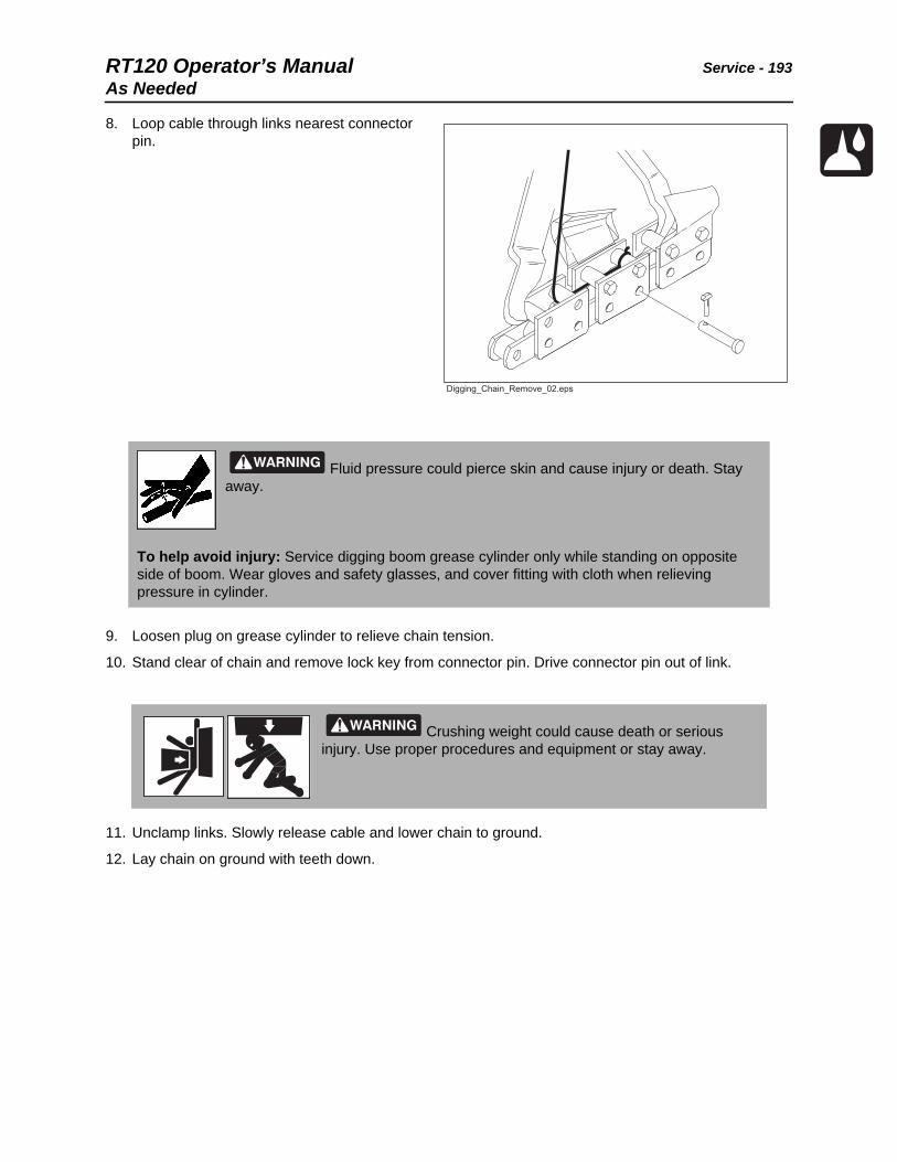
RT120 Operator’s Manual Service - 193As Needed
8. Loop cable through links nearest connector pin.
9. Loosen plug on grease cylinder to relieve chain tension.
10. Stand clear of chain and remove lock key from connector pin. Drive connector pin out of link.
11. Unclamp links. Slowly release cable and lower chain to ground.
12. Lay chain on ground with teeth down.
Fluid pressure could pierce skin and cause injury or death. Stay away.
To help avoid injury: Service digging boom grease cylinder only while standing on opposite side of boom. Wear gloves and safety glasses, and cover fitting with cloth when relieving pressure in cylinder.
Crushing weight could cause death or serious injury. Use proper procedures and equipment or stay away.
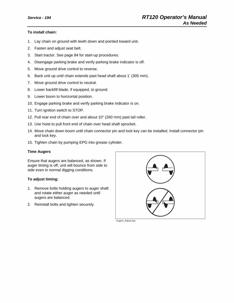
Service - 194 RT120 Operator’s ManualAs Needed
To install chain:
1. Lay chain on ground with teeth down and pointed toward unit.
2. Fasten and adjust seat belt.
3. Start tractor. See page 84 for start-up procedures.
4. Disengage parking brake and verify parking brake indicator is off.
5. Move ground drive control to reverse.
6. Back unit up until chain extends past head shaft about 1’ (305 mm).
7. Move ground drive control to neutral.
8. Lower backfill blade, if equipped, to ground.
9. Lower boom to horizontal position.
10. Engage parking brake and verify parking brake indicator is on.
11. Turn ignition switch to STOP.
12. Pull rear end of chain over and about 10" (260 mm) past tail roller.
13. Use hoist to pull front end of chain over head shaft sprocket.
14. Move chain down boom until chain connector pin and lock key can be installed. Install connector pin and lock key.
15. Tighten chain by pumping EPG into grease cylinder.
Time Augers
Ensure that augers are balanced, as shown. If auger timing is off, unit will bounce from side to side even in normal digging conditions.
To adjust timing:
1. Remove bolts holding augers to auger shaft and rotate either auger as needed until augers are balanced.
2. Reinstall bolts and tighten securely.

RT120 Operator’s Manual Service - 195As Needed
Plow
Clean Feed Tube
Clean feed tube as needed.
Replace Sod Cutter and Blade
Replace worn sod cutter and plow blade as needed.

Service - 196 RT120 Operator’s ManualAs Needed
Check Plow Blade Bolts
Check plow blade bolts as needed. If loose, use Loctite® 242 (blue) and tighten bolts to 210 ft•lb (285 N•m).
Backhoe
Replace Pins and Bushings
Replace pins (1) and bushings (2) when worn or damaged.

RT120 Operator’s Manual Specifications - 197RT120 Tractor
Specifications
RT120 Tractor
Dimensions U.S. Metric
A2 Angle of approach 25° 25°
H1 Height 115 in 2.92 m
L1 Nose to rear mount length 125 in 3.17 m
L2 Length - transport 154 in 3.91 m
L4 Wheelbase 79 in 2.00 m
W2 Width 82 in 2.1 m
W4 Tread 64 in 1.63 m
General
Ditch Witch model RT120 tractor, 4-wheel drive, rigid frame, hydrostatic ground drive through rubber tires, 4-wheel steering, hydrostatic attachment drive, riding unit.
t41om034w.eps
L1L1
L4L4
A2A2
W4W4
H1H1
W2W2L2L2

Specifications - 198 RT120 Operator’s ManualRT120 Tractor
Operation U.S. Metric
Forward speeds
Low/Low 0.5 mph 0.8 km/h
Low/High 1.3 mph 2.1 km/h
High/Low 4.5 mph 7.2 km/h
High/High 9.2 mph 14.8 km/h
Reverse speeds
Low/Low 0.5 mph 0.8 km/h
Low/High 1.3 mph 2.1 km/h
High/Low 3.2 mph 5.1 km/h
High/High 5.5 mph 8.8 km/h
Vehicle clearance circle (SAE) wall to wall with optional backfill blade
Front steer only 34.3 ft 10.4 m
Front and rear steer 20.8 ft 6.3 m
Ground clearance 14 in 356 mm
Basic unit weight 8,700 lb 3,946 kg
Maximum allowable tractor weight 19,300 lb 8,754 kg
Front counterweight 1300 lb 590 kg
Side counterweight (each) 250 lb 114 kg
Backfill Blade (optional) U.S. Metric
Blade width 80 in 2.03 m
Blade height 17 in 430 mm
Lift height above ground 21 in 530 mm
Blade drop below ground 11 in 280 mm
Maximum swing angle (left/right) 30° 30°
Tilt angle (up/down) 24° 24°

RT120 Operator’s Manual Specifications - 199RT120 Tractor
Power Plant U.S. Metric
Engine: Deutz Tier 3 or Tier 4i TCD 3.6 L4 diesel, liquid cooled, 4 cyl, common rail direct injection, turbocharged with charge air cooling, and Tier 4i with exhaust after treatment system (EAT).
Displacement 221 in3 3.6 L
Bore 3.86 in 98 mm
Stroke 4.72 in 120 mm
Engine manufacturer’s gross power rating per SAE J1349 121 hp 90 kW
Estimated net power per SAE J1349 113 hp 84 kW
Rated speed 2300 rpm 2300 rpm
Maximum engine tilt angles*
Longitudinal 30° 30°
Lateral 30° 30°
*Exceeding these operating angles will cause engine damage. This DOES NOT IMPLY machine is stable to maximum angle of safe engine operation.
Emissions compliance EPA Tier 4i EU Stage lllb
Emissions compliance (Rest of World) EPA Tier 3 EU Stage llla
Power Train
Ground drive: hydrostatic
Differentials: planetary front and rear with optional rear steering
Service brake: hydrostatic disc, foot operated
Secondary brake: disc, foot operated
Parking brake: disc, hand operated
Tires: 38 x 18.00-20 14-ply bar lug flotation; inflate to 72 psi (4.9 bar)
Attachment drive: hydrostatic, lever-operated speed infinitely variable from zero to maximum
Hydraulic System U.S. Metric
Ground drive pump capacity at 2300 rpm 27.9 gpm 106 L/min
Ground drive pump relief pressure at 2300 rpm 5000 psi 345 bar
Attachment pump capacity at 2300 rpm 45.5 gpm 172 L/min

Specifications - 200 RT120 Operator’s ManualRT120 Tractor
Unless otherwise specified, all figures are for standard equipment only.
Specifications are called out according to SAE recommended procedures. Specifications are general and subject to change without notice. If exact measurements are required, equipment should be weighed and measured. Due to selected options, delivered equipment may not necessarily match that described.
Attachment pump relief pressure at 2300 rpm 6090 psi 420 bar
Auxiliary pump capacity at 2300 rpm 13.6 gpm 51.5 L/min
Auxiliary pump relief pressure at 2300 rpm 2500 psi 172.4 bar
Fluid Capacities U.S. Metric
Fuel tank 38 gal 144 L
Engine oil 8.5 qt 8 L
Hydraulic reservoir 24 gal 91 L
Hydraulic system 29 gal 110 L
Cooling system 12.3 qt 11.6 L
Battery (2 used)
Group 65, SAE res. cap 165 min., SAE cold crank @ 0° F (-18° C), 875 amp
Auxiliary power outlet - 12 volt, 10 amp
Vibration Level
Average vibration transmitted to the operator’s hand and whole body while plowing is 14.6 and 0.5 m/sec2 respectively.
Operator seat complies with ISO 7096.
Noise Levels
Operator ear sound pressure level is 92 dBa per ISO 6394.
Exterior sound power level is 109 dBa per ISO 6393.

RT120 Operator’s Manual Specifications - 201H910 Trencher
H910 Trencher
Dimensions U.S. Metric
A3 Angle of departure 28° 28°
A Trench depth, maximum 97 in 2.46 m
B Trench width, maximum 24 in 610 mm
C Boom travel down 65° 65°
C1 Boom travel up 50° 50°
E1 Centerline of trench to outside edge, left 41 in 1.04 m
E2 Centerline of trench to outside edge, right 32 in 8.13 mm
F Headshaft height, digging chain 32 in 813 mm
H1 Transport height 124 in 3.15 m
L2 Transport length 112 in 2.85 m
L Headshaft overhang 40 in 1.0 m
N Soil discharge reach 33 in 843 mm
Attachment weight 1750 lb 794 kg
t41om035w.eps

Specifications - 202 RT120 Operator’s ManualH910 Trencher
Operation U.S. Metric
Headshaft speeds @2300 rpm
Ratio low 220 rpm 220 rpm
Ratio standard 270 rpm 270 rpm
Ratio high (not recommended) 362 rpm 362 rpm
Digging chain speeds
Ratio low 628 ft/min 191 m/min
Ratio standard 767 ft/min 234 m/min
Ratio high (not recommended) 1032 ft/min 315 m/min
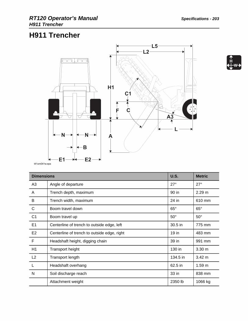
RT120 Operator’s Manual Specifications - 203H911 Trencher
H911 Trencher
Dimensions U.S. Metric
A3 Angle of departure 27° 27°
A Trench depth, maximum 90 in 2.29 m
B Trench width, maximum 24 in 610 mm
C Boom travel down 65° 65°
C1 Boom travel up 50° 50°
E1 Centerline of trench to outside edge, left 30.5 in 775 mm
E2 Centerline of trench to outside edge, right 19 in 483 mm
F Headshaft height, digging chain 39 in 991 mm
H1 Transport height 130 in 3.30 m
L2 Transport length 134.5 in 3.42 m
L Headshaft overhang 62.5 in 1.59 m
N Soil discharge reach 33 in 838 mm
Attachment weight 2350 lb 1066 kg
t41om041w.eps

Specifications - 204 RT120 Operator’s ManualH911 Trencher
Operation U.S. Metric
Headshaft speeds
Ratio low 220 rpm 220 rpm
Ratio standard 270 rpm 270 rpm
Ratio high (not recommended) 362 rpm 362 rpm
Digging chain speeds
Ratio low 628 ft/min 191 m/min
Ratio standard 767 ft/min 234 m/min
Ratio high (not recommended) 1032 ft/min 315 m/min

RT120 Operator’s Manual Specifications - 205H932 Plow
H932 Plow
Dimensions U.S. Metric
A Cover depth* 36 in 920 mm
A’ Penetration* 40 in 1.02 m
A3’ Angle of departure, transport, no blade 30° 30°
A3 Angle of departure, transport, 24” (610-mm) blade 27° 27°
Angle of departure, transport, 30” (760-mm) blade 23° 23°
H Angle of depression, plow max. 10° 10°
H2 Height transport 96 in 2.49 m
J Blade ground clearance, 30” (760-mm) blade 24 in 610 mm
L2 Attachment length, fully lowered, no blade 102 in 2.59 m
L2’ Attachment length, fully raised, no blade 69 in 1.73 m
Plow swing angle 43° 43°
Inclusive blade steer angle 89° 89°
t41om036w.eps

Specifications - 206 RT120 Operator’s ManualH932 Plow
*Suggested maximum. Plow blade used will be determined by job requirements and soil conditions
Center of plow to outside edge of machine, left 40 in 1.02 m
Center of plow to outside edge of machine, right 42 in 1.07 m
Operation U.S. Metric
Plow vibrator force @ 1800 rpm 35,215 lb 157 kN
Maximum material diameter
Pulled 3 in 80 mm
Fed 2 in 50 mm
General U.S. Metric
Attachment weight, without plow blade 2400 lb 1100 kg
Counterweight required. Contact your local Ditch Witch dealer for counterweight requirements.
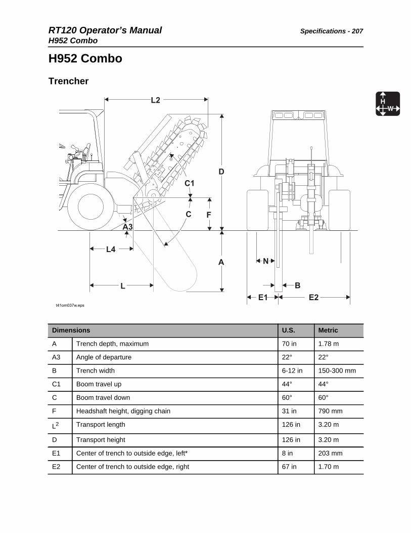
RT120 Operator’s Manual Specifications - 207H952 Combo
H952 Combo
Trencher
Dimensions U.S. Metric
A Trench depth, maximum 70 in 1.78 m
A3 Angle of departure 22° 22°
B Trench width 6-12 in 150-300 mm
C1 Boom travel up 44° 44°
C Boom travel down 60° 60°
F Headshaft height, digging chain 31 in 790 mm
L2 Transport length 126 in 3.20 m
D Transport height 126 in 3.20 m
E1 Center of trench to outside edge, left* 8 in 203 mm
E2 Center of trench to outside edge, right 67 in 1.70 m
t41om037w.eps

Specifications - 208 RT120 Operator’s ManualH952 Combo
N Spoil discharge reach, minimum 19 in 480 mm
L Headshaft overhang 40 in 1.02 m
*Left edge of machine is defined as outside of digging chain guard
Operation U.S. Metric
Maximum headshaft speed
Ratio low 220 rpm 220 rpm
Ratio standard 270 rpm 270 rpm
Ratio high (not recommended) 362 rpm 362 rpm
Maximum digging chain speed
Ratio low 628 ft/min 191 m/min
Ratio standard 767 ft/min 234 m/min
Ratio high 1032 ft/min 315 m/min
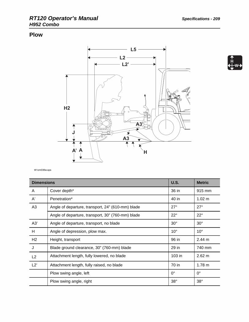
RT120 Operator’s Manual Specifications - 209H952 Combo
Plow
Dimensions U.S. Metric
A Cover depth* 36 in 915 mm
A’ Penetration* 40 in 1.02 m
A3 Angle of departure, transport, 24” (610-mm) blade 27° 27°
Angle of departure, transport, 30” (760-mm) blade 22° 22°
A3’ Angle of departure, transport, no blade 30° 30°
H Angle of depression, plow max. 10° 10°
H2 Height, transport 96 in 2.44 m
J Blade ground clearance, 30” (760-mm) blade 29 in 740 mm
L2 Attachment length, fully lowered, no blade 103 in 2.62 m
L2’ Attachment length, fully raised, no blade 70 in 1.78 m
Plow swing angle, left 0° 0°
Plow swing angle, right 38° 38°
t41om036w.eps

Specifications - 210 RT120 Operator’s ManualH952 Combo
* Suggested maximum. Plow blade used will be determined by job requirements and soil conditions.
**Left edgoe of machine is defined as outside of digging chain guard.
Inclusive blade steer angle 89° 89°
Center of plow to outside edge of machine, left 45 in 1.14 m
Center of plow to outside edge of machine, right 37 in 940 m
Operational U.S. Metric
Plow vibrator force @ 1800 rpm 35,215 lb 156,644 kN
Maximum material diameter
Pulled 3 in 76 mm
Fed 2 in 51 mm
General U.S. Metric
Attachment weight without boom, chain, or plow blade 3065 lb 1390 kg
Counterweight required. Contact your local Ditch Witch dealer for counterweight requirements.
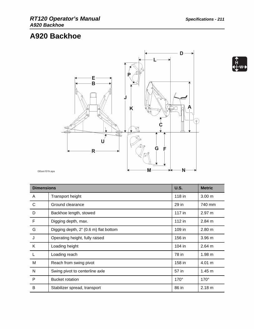
RT120 Operator’s Manual Specifications - 211A920 Backhoe
A920 Backhoe
Dimensions U.S. Metric
A Transport height 118 in 3.00 m
C Ground clearance 29 in 740 mm
D Backhoe length, stowed 117 in 2.97 m
F Digging depth, max. 112 in 2.84 m
G Digging depth, 2” (0.6 m) flat bottom 109 in 2.80 m
J Operating height, fully raised 156 in 3.96 m
K Loading height 104 in 2.64 m
L Loading reach 78 in 1.98 m
M Reach from swing pivot 158 in 4.01 m
N Swing pivot to centerline axle 57 in 1.45 m
P Bucket rotation 170° 170°
B Stabilizer spread, transport 86 in 2.18 m

Specifications - 212 RT120 Operator’s ManualA920 Backhoe
*Lift capacities are for a stationary machine supported by stabilizers.
E Backhoe or basic unit width 82 in 2.08 m
R Stabilizer spread, operating 121 in 3.07 m
U Leveling angle 10° 10°
General U.S. Metric
Bucket
Width 12-24 in 305-610 mm
Capacity 1.7-3.5 ft3 0.05-.1 m3
Backhoe weight with 18” (686 mm) bucket 3300 lb 1497 kg
Lift capacity, boom over end and swing arc, SAE*
@ 48” (1.2 m) 1170 lb 530 kg
@ ground level 1250 lb 567 kg
@ 72” (1.8 m) 1184 lb 537 kg
Lift capacity, dipperstick over end and swing arc, SAE*
@ 52” (1.3 m) 3184 lb 1444 kg
@ 96” (2.4 m) 2242 lb 1017 kg
Swing arc 180° 180°
Digging force
Using bucket cylinder 6600 lb 2994 kg
Using dipperstick cylinder 4475 lb 2030 kg

RT120 Operator’s Manual Specifications - 213RC120 Reel Carrier
RC120 Reel Carrier
Dimensions U.S. Metric
L5 Distance from backfill blade to outside edge of reel carrier 76 in 1.93 m
N Maximum reel diameter 84 in 2.13 m
Internal width 54 in 1.37 m
Capacity 2500 lb 1134 kg
Attachment weight with six 96 lb (44 kg) counterweights 1600 lb 726 kg
t41om038w.eps
NN
L5L5
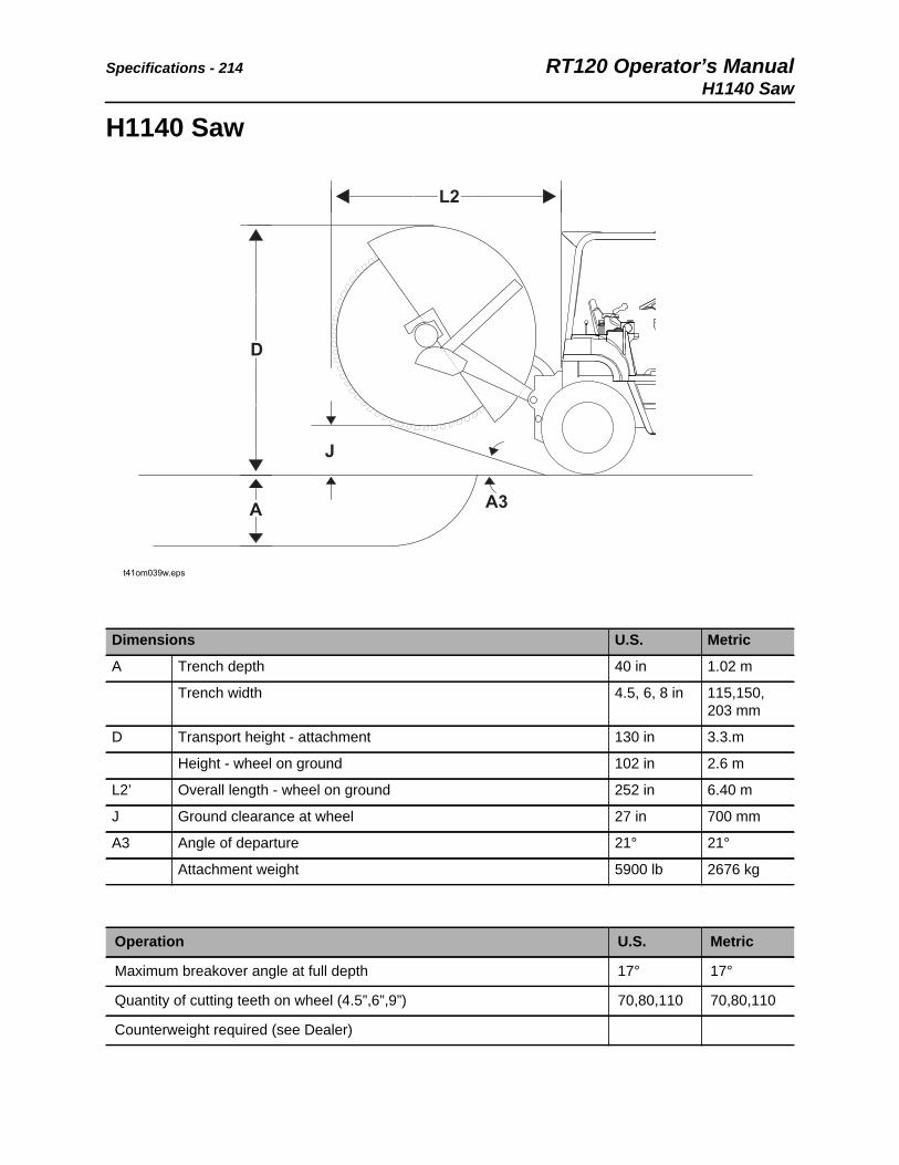
Specifications - 214 RT120 Operator’s ManualH1140 Saw
H1140 Saw
Dimensions U.S. Metric
A Trench depth 40 in 1.02 m
Trench width 4.5, 6, 8 in 115,150, 203 mm
D Transport height - attachment 130 in 3.3.m
Height - wheel on ground 102 in 2.6 m
L2’ Overall length - wheel on ground 252 in 6.40 m
J Ground clearance at wheel 27 in 700 mm
A3 Angle of departure 21° 21°
Attachment weight 5900 lb 2676 kg
Operation U.S. Metric
Maximum breakover angle at full depth 17° 17°
Quantity of cutting teeth on wheel (4.5”,6”,9”) 70,80,110 70,80,110
Counterweight required (see Dealer)
t41om039w.eps
L2L2
DD
JJ
AA A3A3
RT120 Operator’s Manual Specifications - 215H1140 Saw
Power Train
Cutting bit types: Roatating, self-sharpening conical bit with spring retainer. Carbide cap or carbide insert available.
Cutter wheel type: Steel wheel with 10 bolt-on segments.
Wheel motor: 107 in3 (1747 cc) radial piston with pair of tapered roller bearings.
Wheel shaft bearing: 3 in (76 mm) flanged cartridge double row, sperical roller bearing.
Lift provision: Two 4 in (107 mm) hydraulic cylinders.
Gauge shoes: Minimize shock, bearing load, and vibration when cutting and move spoils away from trench.
Spoil placement: Both sides approximatelt 12-18 in (305-457 mm) from trench.

Specifications - 216 RT120 Operator’s ManualH1140 Saw

RT120 Operator’s Manual Support - 217Procedure
CMW®
Support
Procedure
Notify your dealer immediately of any malfunction or failure of Ditch Witch® equipment.
Always give model, serial number, and approximate date of your equipment purchase. This information should be recorded and placed on file by the owner at the time of purchase.
Return damaged parts to dealer for inspection and warranty consideration if in warranty time frame.
Order genuine Ditch Witch replacement or repair parts from your authorized Ditch Witch dealer. Use of another manufacturer's parts may void warranty consideration.
Resources
Publications
Contact your Ditch Witch dealer for publications and videos covering safety, operation, service, and repair of your equipment.
Ditch Witch Training
For information about on-site, individualized training, contact your Ditch Witch dealer.
Warranty - 218 RT120 Operator’s Manual
CMW®
Warranty
Ditch Witch® Equipment and Replacement PartsLimited Warranty Policy
Subject to the limitation and exclusions herein, free replacement parts will be provided at any authorized Ditch Witch dealership for any Ditch Witch equipment or parts manufactured by The Charles Machine Works, Inc. (CMW) that fail due to a defect in material or workmanship within one (1) year of first commercial use. Free labor will be provided at any authorized Ditch Witch dealership for installation of parts under this warranty during the first year following “initial commercial” use of the serial-numbered Ditch Witch equipment on which it is installed. The customer is responsible for transporting their equipment to an authorized Ditch Witch dealership for all warranty work.
Exclusions from Product Warranty• All incidental or consequential damages.
• All defects, damages, or injuries caused by misuse, abuse, improper installation, alteration, neglect, or uses other than those for which products were intended.
• All defects, damages, or injuries caused by improper training, operation, or servicing of products in a manner inconsistent with manufacturer’s recommendations.
• All engines and engine accessories (these are covered by original manufacturer’s warranty).
• Tires, belts, and other parts which may be subject to another manufacturer’s warranty (such warranty will be available to purchaser).
• ALL IMPLIED WARRANTIES NOT EXPRESSLY STATED HEREIN, INCLUDING ANY WARRANTY OF FITNESS FOR A PARTICULAR PURPOSE AND MERCHANTABILITY.
IF THE PRODUCTS ARE PURCHASED FOR COMMERCIAL PURPOSES, AS DEFINED BY THE UNIFORM COMMERCIAL CODE, THEN THERE ARE NO WARRANTIES WHICH EXTEND BEYOND THE FACE HEREOF AND THERE ARE NO IMPLIED WARRANTIES OF ANY KIND WHICH EXTEND TO A COMMERCIAL BUYER. ALL OTHER PROVISIONS OF THIS LIMITED WARRANTY APPLY INCLUDING THE DUTIES IMPOSED.
Ditch Witch products have been tested to deliver acceptable performance in most conditions. This does not imply they will deliver acceptable performance in all conditions. Therefore, to assure suitability, products should be operated under anticipated working conditions prior to purchase.
Defects will be determined by an inspection within thirty (30) days of the date of failure of the product or part by CMW or its authorized dealer. CMW will provide the location of its inspection facilities or its nearest authorized dealer upon inquiry. CMW reserves the right to supply remanufactured replacements parts under this warranty as it deems appropriate.
Extended warranties are available upon request from your local Ditch Witch dealer or CMW.
Some states do not allow exclusion or limitation of incidental or consequential damages, so above limitation of exclusion may not apply. Further, some states do not allow exclusion of or limitation of how long an implied warranty lasts, so the above limitation may not apply. This limited warranty gives product owner specific legal rights and the product owner may also have other rights which vary from state to state.
For information regarding this limited warranty, contact CMW’s Product Support department, P.O. Box 66, Perry, OK 73077-0066, or contact your local Ditch Witch dealer.
First version: 1/91; Latest version: 11/11


RT120 Operator’s Manual Service Record - 221
CMW®
Service Record
Service Performed Date Hours

CMW®
Service Record - 222 RT120 Operator’s Manual
Service Performed Date Hours