ditch witch 1820 operators manual - ben's rental and...
TRANSCRIPT
1820 - SERVICE 1SERIAL NUMBER RECORD
1820 - SERVICE 1SERIAL NUMBER RECORD
SERVICE
SERIAL NUMBER RECORD
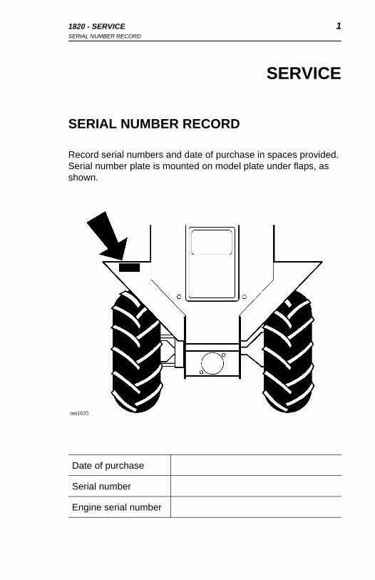
Record serial numbers and date of purchase in spaces provided. Serial number plate is mounted on model plate under flaps, as shown.
Date of purchase
Serial number
Engine serial number
om1635
SERVICE
SERIAL NUMBER RECORD
Record serial numbers and date of purchase in spaces provided. Serial number plate is mounted on model plate under flaps, as shown.
Date of purchase
Serial number
Engine serial number
om1635

2 1820 - SERVICESUPPORT PROCEDURE
2 1820 - SERVICESUPPORT PROCEDURE
SUPPORT PROCEDURE
Notify your dealer immediately of any malfunction or failure of Ditch Witch equipment.
Always give model, serial number, and approximate date of equipment purchase. This information should be recorded and placed on file by owner at time of purchase.
Return damaged parts to dealer for inspection and warranty consideration.
Order genuine Ditch Witch replacement parts from your authorized ditch Witch dealer. Use of another manufacturer’s parts may void warranty.
RESOURCES
Publications
Contact your Ditch Witch dealer for publications and videos covering safety, operation, service, and repair of your equipment.
Ditch Witch TrainingFor information about on-site, individualized training, contact your Ditch Witch dealer.

1820 - FOREWORD 31820 - FOREWORD 3
FOREWORD
This manual is an important part of your equipment. It provides safety information and operation instructions to help you use and maintain your Ditch Witch equipment.
Read this manual before using your equipment. Keep it with the equipment at all times for future reference. If you sell your equipment, be sure to give this manual to the new owner.
If you need a replacement copy, contact your Ditch Witch dealer. If you need assistance in locating a dealer, visit our website at www.ditchwitch.com or write to the following address:
The Charles Machine Works, Inc.Attn: Marketing DepartmentPO Box 66Perry, OK 73077-0066 USA
The descriptions and specifications in this manual are subject to change. The Charles Machine Works, Inc. reserves the right to improve equipment. Some product improvements may have taken place after this manual was published. For the latest information on Ditch Witch equipment, see your Ditch Witch dealer.
Thank you for buying and using Ditch Witch equipment.
4 1820 - FOREWORD 4 1820 - FOREWORD
Operator's Manual1820
Issue Number 5.2/OP-9/04Part Number 054-485
Copyright 1994, 1995, 2003, 2004by The Charles Machine Works, Inc.,
Perry, Oklahoma, 73077-0066.
, Ditch Witch, CMW, AutoCrowd, Modularmatic, Jet Trac, Roto Witch, Subsite, Fluid Miser, Perma-Soil, Power Pipe, Super Witch, Super Witch II, Pierce Airrow, The Underground, and The Underground Authority Worldwide are registered trademarks of The Charles Machine Works, Inc.

1820 - CONTENTS 51820 - CONTENTS 5
CONTENTS
SERVICE . . . . . . . . . . . . . . . . . . . . . . . . . . . . . . . . . . . . . . . 1
Serial Number Record . . . . . . . . . . . . . . . . . . . . . . . . . 1
Support Procedure . . . . . . . . . . . . . . . . . . . . . . . . . . . . 2
Resources . . . . . . . . . . . . . . . . . . . . . . . . . . . . . . . . . . 2
FOREWORD . . . . . . . . . . . . . . . . . . . . . . . . . . . . . . . . . . . . 3
OVERVIEW . . . . . . . . . . . . . . . . . . . . . . . . . . . . . . . . . . . . . 9
CONTROLS . . . . . . . . . . . . . . . . . . . . . . . . . . . . . . . . . . . . 11
Console . . . . . . . . . . . . . . . . . . . . . . . . . . . . . . . . . . . 11
Descriptions . . . . . . . . . . . . . . . . . . . . . . . . . . . . . . . . 12
SAFETY . . . . . . . . . . . . . . . . . . . . . . . . . . . . . . . . . . . . . . . 19
Underground Hazards . . . . . . . . . . . . . . . . . . . . . . . . 20
Emergency Procedures . . . . . . . . . . . . . . . . . . . . . . . 20
Safety Alert Classifications . . . . . . . . . . . . . . . . . . . . . 22
Safety Alerts . . . . . . . . . . . . . . . . . . . . . . . . . . . . . . . . 23
TRANSPORTATION . . . . . . . . . . . . . . . . . . . . . . . . . . . . . 29
Lifting . . . . . . . . . . . . . . . . . . . . . . . . . . . . . . . . . . . . . 29
Hauling . . . . . . . . . . . . . . . . . . . . . . . . . . . . . . . . . . . . 30
Loading . . . . . . . . . . . . . . . . . . . . . . . . . . . . . . . . . . . 31
Towing . . . . . . . . . . . . . . . . . . . . . . . . . . . . . . . . . . . . 33
CONTENTS
SERVICE . . . . . . . . . . . . . . . . . . . . . . . . . . . . . . . . . . . . . . . 1
Serial Number Record . . . . . . . . . . . . . . . . . . . . . . . . . 1
Support Procedure . . . . . . . . . . . . . . . . . . . . . . . . . . . . 2
Resources . . . . . . . . . . . . . . . . . . . . . . . . . . . . . . . . . . 2
FOREWORD . . . . . . . . . . . . . . . . . . . . . . . . . . . . . . . . . . . . 3
OVERVIEW . . . . . . . . . . . . . . . . . . . . . . . . . . . . . . . . . . . . . 9
CONTROLS . . . . . . . . . . . . . . . . . . . . . . . . . . . . . . . . . . . 11
Console . . . . . . . . . . . . . . . . . . . . . . . . . . . . . . . . . . . 11
Descriptions . . . . . . . . . . . . . . . . . . . . . . . . . . . . . . . . 12
SAFETY . . . . . . . . . . . . . . . . . . . . . . . . . . . . . . . . . . . . . . 19
Underground Hazards . . . . . . . . . . . . . . . . . . . . . . . . 20
Emergency Procedures . . . . . . . . . . . . . . . . . . . . . . . 20
Safety Alert Classifications . . . . . . . . . . . . . . . . . . . . 22
Safety Alerts . . . . . . . . . . . . . . . . . . . . . . . . . . . . . . . 23
TRANSPORTATION . . . . . . . . . . . . . . . . . . . . . . . . . . . . . 29
Lifting . . . . . . . . . . . . . . . . . . . . . . . . . . . . . . . . . . . . . 29
Hauling . . . . . . . . . . . . . . . . . . . . . . . . . . . . . . . . . . . 30
Loading . . . . . . . . . . . . . . . . . . . . . . . . . . . . . . . . . . . 31
Towing . . . . . . . . . . . . . . . . . . . . . . . . . . . . . . . . . . . . 33

6 1820 - CONTENTS 6 1820 - CONTENTS
OPERATION . . . . . . . . . . . . . . . . . . . . . . . . . . . . . . . . . . . 35
Inspect Machine . . . . . . . . . . . . . . . . . . . . . . . . . . . . . 35
Startup . . . . . . . . . . . . . . . . . . . . . . . . . . . . . . . . . . . . 37
Driving. . . . . . . . . . . . . . . . . . . . . . . . . . . . . . . . . . . . . 38
TRENCHING ATTACHMENT . . . . . . . . . . . . . . . . . . . . . . 39
Operating Tips . . . . . . . . . . . . . . . . . . . . . . . . . . . . . . 40
DRILLING ATTACHMENT . . . . . . . . . . . . . . . . . . . . . . . . 43
Drilling Attachment Control Descriptions . . . . . . . . . . 44
Prepare Jobsite and Equipment . . . . . . . . . . . . . . . . 45
Drill . . . . . . . . . . . . . . . . . . . . . . . . . . . . . . . . . . . . . . . 47
Add Rod . . . . . . . . . . . . . . . . . . . . . . . . . . . . . . . . . . . 49
Backream . . . . . . . . . . . . . . . . . . . . . . . . . . . . . . . . . . 49
Disassemble Joints . . . . . . . . . . . . . . . . . . . . . . . . . . 50
Optional Equipment . . . . . . . . . . . . . . . . . . . . . . . . . . 50
LUBRICATION . . . . . . . . . . . . . . . . . . . . . . . . . . . . . . . . . 51
Schedule . . . . . . . . . . . . . . . . . . . . . . . . . . . . . . . . . . 52
Engine Oil . . . . . . . . . . . . . . . . . . . . . . . . . . . . . . . . . 54
Hydraulic Oil . . . . . . . . . . . . . . . . . . . . . . . . . . . . . . . 55
Pivot Tube . . . . . . . . . . . . . . . . . . . . . . . . . . . . . . . . . 57
Trail Wheel Bearing . . . . . . . . . . . . . . . . . . . . . . . . . . 57
Cross and Bearing . . . . . . . . . . . . . . . . . . . . . . . . . . . 57
Reducer Boxes . . . . . . . . . . . . . . . . . . . . . . . . . . . . . 58
OPERATION . . . . . . . . . . . . . . . . . . . . . . . . . . . . . . . . . . . 35
Inspect Machine . . . . . . . . . . . . . . . . . . . . . . . . . . . . 35
Startup . . . . . . . . . . . . . . . . . . . . . . . . . . . . . . . . . . . . 37
Driving . . . . . . . . . . . . . . . . . . . . . . . . . . . . . . . . . . . . 38
TRENCHING ATTACHMENT . . . . . . . . . . . . . . . . . . . . . . 39
Operating Tips . . . . . . . . . . . . . . . . . . . . . . . . . . . . . . 40
DRILLING ATTACHMENT . . . . . . . . . . . . . . . . . . . . . . . . 43
Drilling Attachment Control Descriptions . . . . . . . . . . 44
Prepare Jobsite and Equipment . . . . . . . . . . . . . . . . 45
Drill . . . . . . . . . . . . . . . . . . . . . . . . . . . . . . . . . . . . . . 47
Add Rod . . . . . . . . . . . . . . . . . . . . . . . . . . . . . . . . . . 49
Backream . . . . . . . . . . . . . . . . . . . . . . . . . . . . . . . . . 49
Disassemble Joints . . . . . . . . . . . . . . . . . . . . . . . . . . 50
Optional Equipment . . . . . . . . . . . . . . . . . . . . . . . . . . 50
LUBRICATION . . . . . . . . . . . . . . . . . . . . . . . . . . . . . . . . . 51
Schedule . . . . . . . . . . . . . . . . . . . . . . . . . . . . . . . . . . 52
Engine Oil . . . . . . . . . . . . . . . . . . . . . . . . . . . . . . . . . 54
Hydraulic Oil . . . . . . . . . . . . . . . . . . . . . . . . . . . . . . . 55
Pivot Tube . . . . . . . . . . . . . . . . . . . . . . . . . . . . . . . . . 57
Trail Wheel Bearing . . . . . . . . . . . . . . . . . . . . . . . . . . 57
Cross and Bearing . . . . . . . . . . . . . . . . . . . . . . . . . . 57
Reducer Boxes . . . . . . . . . . . . . . . . . . . . . . . . . . . . . 58
1820 - CONTENTS 71820 - CONTENTS 7
MAINTENANCE . . . . . . . . . . . . . . . . . . . . . . . . . . . . . . . . . 61
Schedule . . . . . . . . . . . . . . . . . . . . . . . . . . . . . . . . . . 62
Fuel . . . . . . . . . . . . . . . . . . . . . . . . . . . . . . . . . . . . . . 64
Battery . . . . . . . . . . . . . . . . . . . . . . . . . . . . . . . . . . . . 66
Air Filter . . . . . . . . . . . . . . . . . . . . . . . . . . . . . . . . . . . 68
Cooling System . . . . . . . . . . . . . . . . . . . . . . . . . . . . . 70
Belts . . . . . . . . . . . . . . . . . . . . . . . . . . . . . . . . . . . . . . 71
Headshaft Sprocket Bolts . . . . . . . . . . . . . . . . . . . . . . 71
Wheels and Tires . . . . . . . . . . . . . . . . . . . . . . . . . . . . 71
Trenching Attachment . . . . . . . . . . . . . . . . . . . . . . . . 73
SPECIFICATIONS . . . . . . . . . . . . . . . . . . . . . . . . . . . . . . . 77
MAINTENANCE. . . . . . . . . . . . . . . . . . . . . . . . . . . . . . . . . 61
Schedule . . . . . . . . . . . . . . . . . . . . . . . . . . . . . . . . . . 62
Fuel . . . . . . . . . . . . . . . . . . . . . . . . . . . . . . . . . . . . . . 64
Battery . . . . . . . . . . . . . . . . . . . . . . . . . . . . . . . . . . . . 66
Air Filter . . . . . . . . . . . . . . . . . . . . . . . . . . . . . . . . . . . 68
Cooling System . . . . . . . . . . . . . . . . . . . . . . . . . . . . . 70
Belts . . . . . . . . . . . . . . . . . . . . . . . . . . . . . . . . . . . . . . 71
Headshaft Sprocket Bolts . . . . . . . . . . . . . . . . . . . . . 71
Wheels and Tires . . . . . . . . . . . . . . . . . . . . . . . . . . . . 71
Trenching Attachment . . . . . . . . . . . . . . . . . . . . . . . . 73
SPECIFICATIONS . . . . . . . . . . . . . . . . . . . . . . . . . . . . . . 77

8 1820 - CONTENTS 8 1820 - CONTENTS

1820 - OVERVIEW 91820 - OVERVIEW 9
OVERVIEW
The Ditch Witch 1820 is a self-propelled, walk-along, hydraulically steered, two-wheel drive trencher designed to dig in a variety of soils and move large volumes of dirt in a short time.
With an optional drilling unit attached, it is also designed to drill short distances.
A. Control Panel
B. Restraint Bar
C. Digging Chain/Boom
D. Trail Wheel
E. Drive Wheel
om1641x

10 1820 - OVERVIEW 10 1820 - OVERVIEW

1820 - CONTROLS 11CONSOLE
1820 - CONTROLS 11CONSOLE
CONTROLS
CONSOLE
Gasoline Engine Diesel Engine
om1783aom1783
1. Axle lock (blue)
2. Boom control (green)
3. Oil pressure indicator
4. Operator presence switch (red)
5. Speed/Direction control (orange)
6. Hydraulic pump control (orange)
7. Roto Witch control (optional)
8. Digging chain control (yellow)
9. Ignition switch
10. Voltmeter
11. Hourmeter
12. Choke (gas only)
13. Throttle
14. Battery disconnect switch (diesel only)
15. Water temperature gauge (diesel only)
16. Glow plug indicator (diesel only)

12 1820 - CONTROLSCONSOLE
12 1820 - CONTROLSCONSOLE
DESCRIPTIONS
Axle Lock (blue) This lever locks axle (two-wheel drive) or unlocks axle (one-wheel drive).
• Pull to unlock axle. Use unlocked axle to turn trencher.
• Push to lock axle. Use locked axle for straight trenching.
Boom Control (green)This lever raises or lowers digging boom. Can be used only when engine is running.
• Push to lower.
• Pull to raise.
Oil Pressure IndicatorThis light indicates low oil pressure. Light will come on briefly when engine is started. If light comes on when engine is running:
• Turn engine off.
• Check oil level.
• Check for leaks before starting engine.
ic1034
ic1033
om1008.pcx

1820 - CONTROLS 13CONSOLE
1820 - CONTROLS 13CONSOLE
Operator Presence Switch (red)This button prevents machine from running when digging or driving unless operator is pressing switch. Operator presence switch is on top of speed/direction control.
Speed/Direction Control (orange)This lever controls unit speed and direction.
• Push to move toward digging boom.
• Pull to move toward operator position.
• To go faster in either direction, move control farther from center (neutral) position.
• To stop, return to neutral position.
• To turn, move control to left or right while it is in forward, neutral, or reverse position.
om1014.pcx
ic0029h

14 1820 - CONTROLSCONSOLE
14 1820 - CONTROLSCONSOLE
Hydraulic Pump Control (orange)This lever is used to help start cold engine.
• Push to engage
• Pull to disengage.
Roto Witch Control This lever controls optional boring attachment. Refer to Roto Witch Operator's Manual for additional information.
• Push to rotate clockwise.
• Pull to rotate counterclockwise.
Digging Chain Control (yellow) This lever controls digging chain action and speed.
• Push to start digging chain.
• Pull to stop digging chain.
ic1036
ic1085b
ic1035a

1820 - CONTROLS 15CONSOLE
1820 - CONTROLS 15CONSOLE
Ignition SwitchThis switch is used to start engine.
Gasoline Engines:
• Insert key and turn it clockwise to start position (C).
• When engine starts, release key. It will return to on position (B).
• If engine does not start or is killed, turn switch to off position (A), then restart.
Diesel Engines:
• Insert key and turn it clockwise to on position (B). Glow plug indicator will light as engine heats.
• When glow plug indicator goes out, turn key to start position (C).
• When engine starts, release key. It will return to on position (B).
• If engine does not start or is killed, turn switch to off position (A), then restart.
Voltmeter This gauge measures voltage in electric system. Reading should be between 12 and 15 volts with engine running. If not, stop engine and investigate.
ic1084
om1132.pcx
16 1820 - CONTROLSCONSOLE
16 1820 - CONTROLSCONSOLE
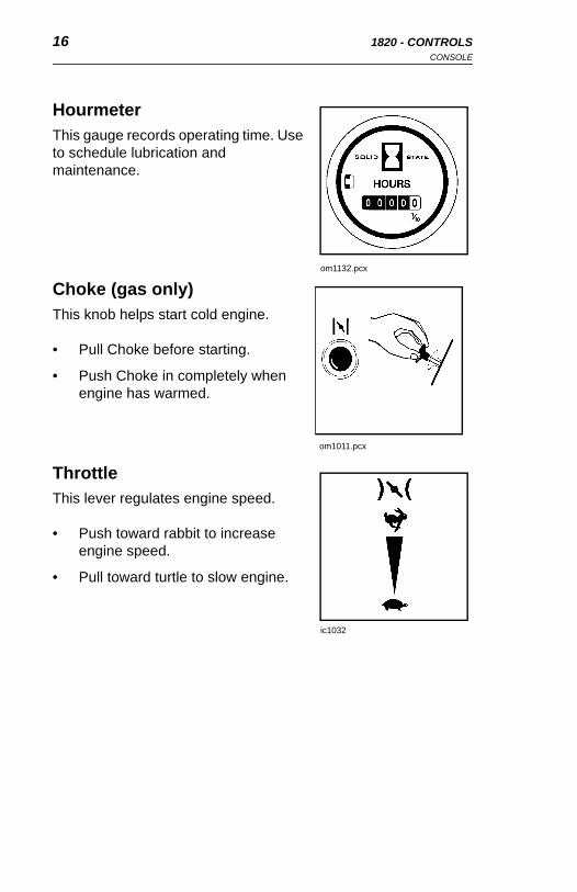
Hourmeter This gauge records operating time. Use to schedule lubrication and maintenance.
Choke (gas only)This knob helps start cold engine.
• Pull Choke before starting.
• Push Choke in completely when engine has warmed.
ThrottleThis lever regulates engine speed.
• Push toward rabbit to increase engine speed.
• Pull toward turtle to slow engine.
om1132.pcx
om1011.pcx
ic1032

1820 - CONTROLS 17CONSOLE
1820 - CONTROLS 17CONSOLE
Water Temperature Gauge (diesel only)This gauge displays temperature of water in cooling system.
Glow Plug Indicator(diesel only)This indicator lights when glow plug is heating.
NOTICE: Do not turn ignition switch to start until glow plug indicator goes out. For complete starting instructions, see OPERATION.
om1463.pcx
ic0026h

18 1820 - CONTROLSCONSOLE
18 1820 - CONTROLSCONSOLE
Battery Disconnect Use for shut-off, when servicing, and during long-term storage.
Battery disconnect is optional on gasoline engines (top illustration) and standard on diesel engines (bottom illustration).
Gasoline engine:
• Turn clockwise to connect battery power.
• Turn counterclockwise to disconnect battery power.
Diesel engine:
• Turn counterclockwise to connect battery power.
• Turn clockwise to disconnect battery power.
om1749
om1486.pcx
1820 - SAFETY 19CONSOLE
1820 - SAFETY 19CONSOLE
SAFETY
Follow these guidelines before operating any jobsite equipment:
• Complete proper training and read operator’s manual before using equipment.
• Contact your local One-Call or utility company. Have all underground lines and cables located and marked before operating equipment. If you damage a utility, contact utility company.
• Classify jobsite based on its hazards and use correct equipment, safety equipment, and work methods for jobsite.
• Mark jobsite clearly and keep spectators away.
• Wear personal protective gear.
• Review jobsite hazards, safety and emergency procedures, and individual responsibilities with all personnel before work begins.
• Replace missing or damaged safety shields and safety signs.
• Use equipment carefully. Stop operation and investigate anything that does not look or feel right.
• Contact your Ditch Witch dealer if you have any question about operation, maintenance, or equipment use.
When you see this safety alert sign, carefully read and follow all instructions. YOUR SAFETY IS AT STAKE.

20 1820 - SAFETYUNDERGROUND HAZARDS
20 1820 - SAFETYUNDERGROUND HAZARDS
UNDERGROUND HAZARDS
Striking underground hazards can cause explosion, electrocution, fire, and exposure to hazardous materials.
Hazards include:
• Electric cables
• Natural gas pipes
• Fiber optic cables
• Water lines
• Sewer lines
• Pipes carrying other chemicals, liquids, or gases
• Storage tanks
EMERGENCY PROCEDURES
If an Electric Line is Damaged
If you suspect an electric line has been damaged and you are off tractor, DO NOT TOUCH TRACTOR. Take the following actions. The order and degree of action will depend upon the situation.
• LEAVE AREA.
• Contact utility company to shut off power.
• Do not return to jobsite or allow anyone into area until given permission by utility company.

1820 - SAFETY 21EMERGENCY PROCEDURES
1820 - SAFETY 21EMERGENCY PROCEDURES
If a Gas Line is Damaged
If you suspect a gas line has been damaged, take the following actions. The order and degree of action will depend on the situation.
• Immediately shut off engine(s), if this can be done safely and quickly.
• Remove any ignition source(s), if this can be done safely and quickly.
• Warn others that a gas line has been cut and that they should leave the area.
• Leave jobsite as quickly as possible.
• Immediately call your local emergency phone number and utility company.
• If jobsite is along street, stop traffic from driving near jobsite.
• Do not return to jobsite until given permission by emergency personnel and utility company.
If a Fiber Optic Cable is Damaged
Do not look into cut ends of fiber optic or unidentified cable. Vision damage can occur.
If Machine Catches on Fire
Perform emergency shutdown procedure and then take the following actions. The order and degree of action will depend on the situation.
• Immediately move battery disconnect switch (if equipped) to disconnect position.
• If fire is small and fire extinguisher is available, attempt to extinguish fire.
If fire cannot be extinguished, leave area as quickly as possible and contact emergency personnel.

22 1820 - SAFETYSAFETY ALERT CLASSIFICATIONS
22 1820 - SAFETYSAFETY ALERT CLASSIFICATIONS
SAFETY ALERT CLASSIFICATIONS
You will see the following safety symbols:
indicates an imminently hazardous situation which, if not avoided, will result in death or serious injury.
indicates a potentially hazardous situation which, if not avoided, could result in death or serious injury.
indicates a potentially hazardous situation which, if not avoided, may result in minor or moderate injury.
In this book, you should look for two other words: NOTICE and IMPORTANT.
NOTICE can keep you from doing something that might damage the machine or someone's property. It may also be used to alert against unsafe practices.
IMPORTANT can help you do a better job or make your job easier in some way.

1820 - SAFETY 23SAFETY ALERTS
1820 - SAFETY 23SAFETY ALERTS
SAFETY ALERTS
Deadly gases. Lack of oxygen or presence of gas will cause sickness or death. Provide ventilation.
Moving digging teeth will kill you or cut off arm or leg. Stay away.
NOTICE: Keep everyone at least 6’ (2 m) away from equipment while operating.
Electrical shock. Contacting electrical lines will cause death or serious injury. Know location of lines and stay away.
24 1820 - SAFETYSAFETY ALERTS
24 1820 - SAFETYSAFETY ALERTS
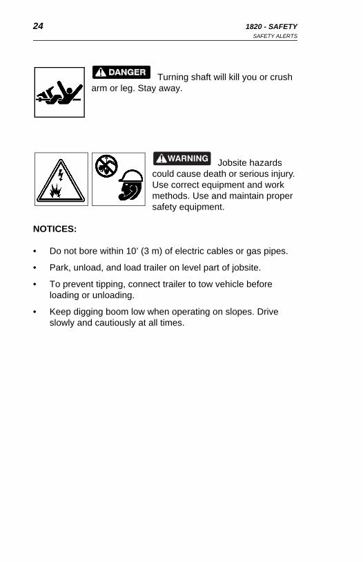
Turning shaft will kill you or crush arm or leg. Stay away.
Jobsite hazards could cause death or serious injury. Use correct equipment and work methods. Use and maintain proper safety equipment.
NOTICES:
• Do not bore within 10’ (3 m) of electric cables or gas pipes.
• Park, unload, and load trailer on level part of jobsite.
• To prevent tipping, connect trailer to tow vehicle before loading or unloading.
• Keep digging boom low when operating on slopes. Drive slowly and cautiously at all times.
1820 - SAFETY 25SAFETY ALERTS
1820 - SAFETY 25SAFETY ALERTS
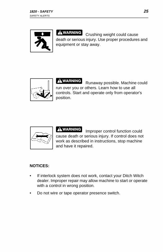
Crushing weight could cause death or serious injury. Use proper procedures and equipment or stay away.
Runaway possible. Machine could run over you or others. Learn how to use all controls. Start and operate only from operator's position.
Improper control function could cause death or serious injury. If control does not work as described in instructions, stop machine and have it repaired.
NOTICES:
• If interlock system does not work, contact your Ditch Witch dealer. Improper repair may allow machine to start or operate with a control in wrong position.
• Do not wire or tape operator presence switch.

26 1820 - SAFETYSAFETY ALERTS
26 1820 - SAFETYSAFETY ALERTS
Incorrect procedures could result in death, injury, or property damage. Learn to use equipment correctly.
NOTICES:
• Keep attachments low when operating on slope. Drive slowly and cautiously at all times.
• Machine may move when chain starts to dig. Allow 3’ (1m) between end of chain and obstacle.
• Digging chain on top side of boom can catch on root or rock. Stand back from console and hold controls loosely.
• Unless otherwise instructed, all service should be performed with engine shut off.
• Refer to engine manufacturer's manual for engine maintenance instructions.
• Before servicing equipment, lower digging boom to ground.

1820 - SAFETY 27SAFETY ALERTS
1820 - SAFETY 27SAFETY ALERTS
Fluid or air under pressure could pierce skin and cause injury or death. Stay away.
NOTICE: Escaping pressurized fluid can cause injury or pierce skin and poison.
• Before disconnecting lines, turn engine off and operate system controls to relieve pressure.
• Before using system, check that all connections are tight and all lines are undamaged.
• Fluid leaks can be hard to detect. Use a piece of cardboard or wood, rather than hands, to search for leaks.
• Wear protective clothing and eye protection.
• If you are injured, seek immediate medical attention from a doctor familiar with this type of injury.
28 1820 - SAFETYSAFETY ALERTS
28 1820 - SAFETYSAFETY ALERTS
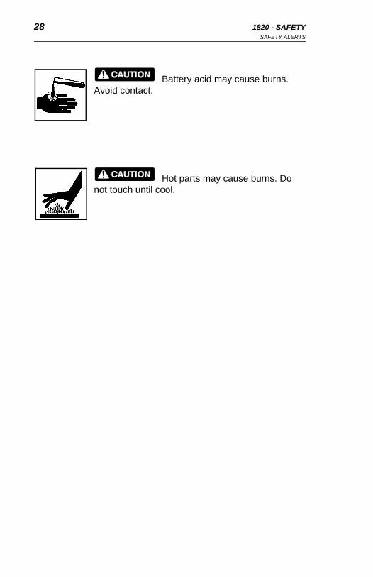
Battery acid may cause burns. Avoid contact.
Hot parts may cause burns. Do not touch until cool.
Battery acid may cause burns. Avoid contact.
Hot parts may cause burns. Do not touch until cool.

1820 - TRANSPORTATION 29LIFTING
1820 - TRANSPORTATION 29LIFTING
TRANSPORTATION
LIFTING
Lifting PointsLifting points are identified by lifting decals. Lifting at any other point is unsafe and can damage machinery.
Lifting UnitBefore lifting, check SPECIFICATIONS. Use a crane capable of supporting the equipment’s size and weight.
Lift trencher by running sling through lift points and through trail wheel housing.
Crushing weight could cause death or serious injury. Use proper procedures and equipment or stay away.
om1362.pcx
om1362.pcx
30 1820 - TRANSPORTATIONHAULING
30 1820 - TRANSPORTATIONHAULING
HAULING
Trencher can be hauled by trailer. Before hauling check the following:
• Check that loading ramps will support weight. See SPECIFICATIONS.
• Check that adequate tiedowns are available.
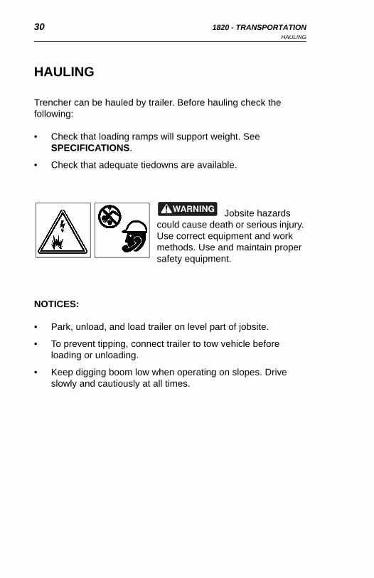
Jobsite hazards could cause death or serious injury. Use correct equipment and work methods. Use and maintain proper safety equipment.
NOTICES:
• Park, unload, and load trailer on level part of jobsite.
• To prevent tipping, connect trailer to tow vehicle before loading or unloading.
• Keep digging boom low when operating on slopes. Drive slowly and cautiously at all times.
HAULING
Trencher can be hauled by trailer. Before hauling check the following:
• Check that loading ramps will support weight. See SPECIFICATIONS.
• Check that adequate tiedowns are available.
Jobsite hazards could cause death or serious injury. Use correct equipment and work methods. Use and maintain proper safety equipment.
NOTICES:
• Park, unload, and load trailer on level part of jobsite.
• To prevent tipping, connect trailer to tow vehicle before loading or unloading.
• Keep digging boom low when operating on slopes. Drive slowly and cautiously at all times.
1820 - TRANSPORTATION 31LOADING
1820 - TRANSPORTATION 31LOADING
LOADING
Load Machine1. Start machine following instructions in OPERATION.
2. Push boom control (green) to lower boom as far as possible without hitting ramps.
3. Engage axle lock (blue).
4. Push throttle (black) to 1/2 open.
EMERGENCY STOP: Release operator presence switch.
5. Move speed/direction control (orange) to forward or reverse position.
To turn, move speed/direction control left or right.
6. Align trencher with ramps or trailer, boom first.
7. Guide trencher onto trailer.
8. When tie down position is reached, move speed/direction control (orange) to neutral position.
9. Push boom control (green) to lower boom.
10. Disengage pump control.
11. Pull throttle to turtle.
12. Turn key to off position.
13. Close fuel shut-off valve on gasoline engine.
14. Tiedown trencher to trailer.
32 1820 - TRANSPORTATIONLOADING
32 1820 - TRANSPORTATIONLOADING
Unload Machine1. Remove tiedowns from trencher.
2. Open fuel shut-off valve on gasoline engine.
3. Start machine.
4. Slowly engage pump control.
5. Move throttle (black) to 1/2 open.
6. Engage axle lock (blue).
7. Pull boom control (green) to raise boom halfway.
8. Use speed/direction control (orange) to slowly back trencher off trailer or down ramps.

1820 - TRANSPORTATION 33TOWING
1820 - TRANSPORTATION 33TOWING
TOWING
This trencher is not designed to be towed. If it must be moved without its own power, optional Spare Hub Assembly should be used.
Spare Hub Assembly is designed for temporary use for distances less than 500’ (150 m) at slow rate of speed. Assembly should only be used for towing.
Spare hub assembly is stored near right drive tire, under guard.
Optional Spare Hub Assembly1. Remove guard covering assembly.
2. Remove two mounting bolts and remove assembly from storage position.
3. Securely block right side of trencher. Right wheel should be off ground.
IMPORTANT: On diesel units, right tire and wheel assembly is filled with tire ballast and weighs approximately 127 lb (58 kg).
4. Remove right wheel.
5. Place assembly on lug bolts and attach with lug nuts. If wrench will not fit through access holes, remove snap ring and outer flange, tighten lug nuts, and replace flange and snap ring.
6. Remove lug nuts from spare hub assembly bolts.
7. Place right wheel on assembly.
8. Securely fasten wheel with lug nuts.
9. Lower trencher.
10. Push axle lock to disengage. Machine will freewheel.
11. Slowly tow trencher.

34 1820 - TRANSPORTATION 34 1820 - TRANSPORTATION

1820 - OPERATION 35INSPECT MACHINE
1820 - OPERATION 35INSPECT MACHINE
OPERATION
INSPECT MACHINE
For safe and efficient use of your machine, check the following before each day's work. Refer to LUBRICATION and MAINTENANCE for additional information.
• General appearance.
• Condition of digging chain, teeth, drive belts, and air filter.
• Fuel lines and fittings for signs of leakage, wear, or other damage.
• Tire pressure. Use reliable tire pressure gauge.
• Engine oil level. Keep oil level at highest line on dipstick.
• Hydraulic oil level. Keep oil level between high and low marks on dipstick.
• Fuel level. Fill tank at end of day to reduce condensation.
• Water level in diesel units. Keep overflow bottle 1/4 to 3/4 full. Add antifreeze as needed.
• Signs are in place and readable.
• Guards and shields are in place.
• Nuts and bolts are tight. Tighten as specified in torque tables in PARTS MANUAL.

36 1820 - OPERATIONSTART-UP
36 1820 - OPERATIONSTART-UP
START-UP
Deadly gases. Lack of oxygen or presence of gas will cause sickness or death. Provide ventilation.
Incorrect procedures could result in death, injury, or property damage. Learn to use equipment correctly.
IMPORTANT: Read engine manufacturer's starting and operating instructions. Follow directions for new engine break-in.
1. Disengage pump control (orange).
2. Check that speed/direction control (orange) is in neutral position.
3. Check that digging chain control (yellow) is at stop position.
4. Open fuel shut-off valve on gasoline engine.
5. Push throttle (black) to 1/4 open.

1820 - OPERATION 37START-UP
1820 - OPERATION 37START-UP
6. Start engine. If engine does not start within ten seconds, release key, allow starter motor to cool, and try to start again. If engine does not start after three tries, check machine.
Gasoline Engine:Choke cold engine. Put key in ignition and turn to start posi-tion. When engine starts, release key. Push choke in.
Diesel Engine:Put key in ignition and turn to on position until glow plug indi-cator goes out. Turn key to start position. When engine starts, release key.
7. Engage pump control (orange) slowly.
8. Idle engine 3-5 minutes before moving. Engine will idle with digging chain disengaged and speed/direction control in neutral position.
9. Check controls for correct operation.
Improper control function could cause death or serious injury. If control does not work as described in instructions, stop machine and have it repaired.
NOTICES:
• If interlock system does not work, contact Ditch Witch dealer. Improper repair may allow machine to start or operate with a control in wrong position.
• Do not wire or tape operator presence switch.
38 1820 - OPERATIONDRIVE
38 1820 - OPERATIONDRIVE
DRIVE
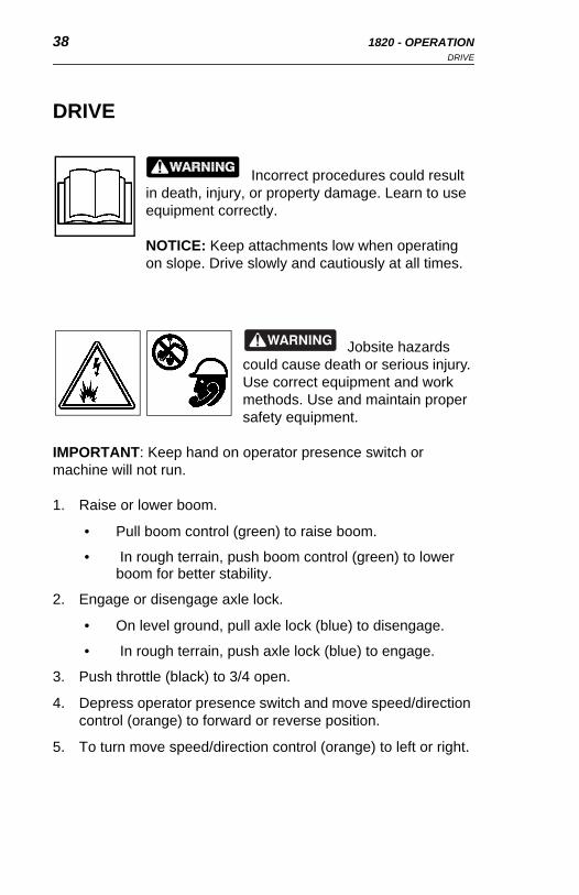
Incorrect procedures could result in death, injury, or property damage. Learn to use equipment correctly.
NOTICE: Keep attachments low when operating on slope. Drive slowly and cautiously at all times.
Jobsite hazards could cause death or serious injury. Use correct equipment and work methods. Use and maintain proper safety equipment.
IMPORTANT: Keep hand on operator presence switch or machine will not run.
1. Raise or lower boom.
• Pull boom control (green) to raise boom.
• In rough terrain, push boom control (green) to lower boom for better stability.
2. Engage or disengage axle lock.
• On level ground, pull axle lock (blue) to disengage.
• In rough terrain, push axle lock (blue) to engage.
3. Push throttle (black) to 3/4 open.
4. Depress operator presence switch and move speed/direction control (orange) to forward or reverse position.
5. To turn move speed/direction control (orange) to left or right.
DRIVE
Incorrect procedures could result in death, injury, or property damage. Learn to use equipment correctly.
NOTICE: Keep attachments low when operating on slope. Drive slowly and cautiously at all times.
Jobsite hazards could cause death or serious injury. Use correct equipment and work methods. Use and maintain proper safety equipment.
IMPORTANT: Keep hand on operator presence switch or machine will not run.
1. Raise or lower boom.
• Pull boom control (green) to raise boom.
• In rough terrain, push boom control (green) to lower boom for better stability.
2. Engage or disengage axle lock.
• On level ground, pull axle lock (blue) to disengage.
• In rough terrain, push axle lock (blue) to engage.
3. Push throttle (black) to 3/4 open.
4. Depress operator presence switch and move speed/direction control (orange) to forward or reverse position.
5. To turn move speed/direction control (orange) to left or right.

1820 - TRENCHING ATTACHMENT 39DRIVE
1820 - TRENCHING ATTACHMENT 39DRIVE
TRENCHING ATTACHMENT
1. Move trencher to starting point.
2. Move speed/direction control to neutral position.
3. Push axle lock (blue) to engage.
4. Push throttle (black) to 1/2 open.
5. Push boom control (green) until boom is 1” (25 mm) from ground.
Moving digging teeth will kill you or cut off arm or leg. Stay away.
NOTICE: Keep everyone at least 6’ (2 m) away from equipment while operating.
Electrical shock. Contacting electrical lines will cause death or serious injury. Know location of lines and stay away.

40 1820 - TRENCHING ATTACHMENTDRIVE
40 1820 - TRENCHING ATTACHMENTDRIVE
Jobsite hazards could cause death or serious injury. Use correct equipment and work methods. Use and maintain proper safety equipment.
NOTICES:
• Do not dig within 10’ (3 m) of electric cables or gas pipes.
• Keep digging boom low when operating on slopes. Drive slowly and cautiously at all times.
6. Push digging chain control to start digging chain.
7. Push boom control (green) slowly to lower digging chain to trench depth.
Incorrect procedures could result in death, injury, or property damage. Learn to use equipment correctly.
NOTICES:
• Machine will lurch when chain starts to dig. Allow 3’ (1 m) between end of chain and obstacle.
• Digging chain on top side of boom can catch on root or rock. Stand back from console and hold controls loosely.
1820 - TRENCHING ATTACHMENT 41DRIVE
1820 - TRENCHING ATTACHMENT 41DRIVE
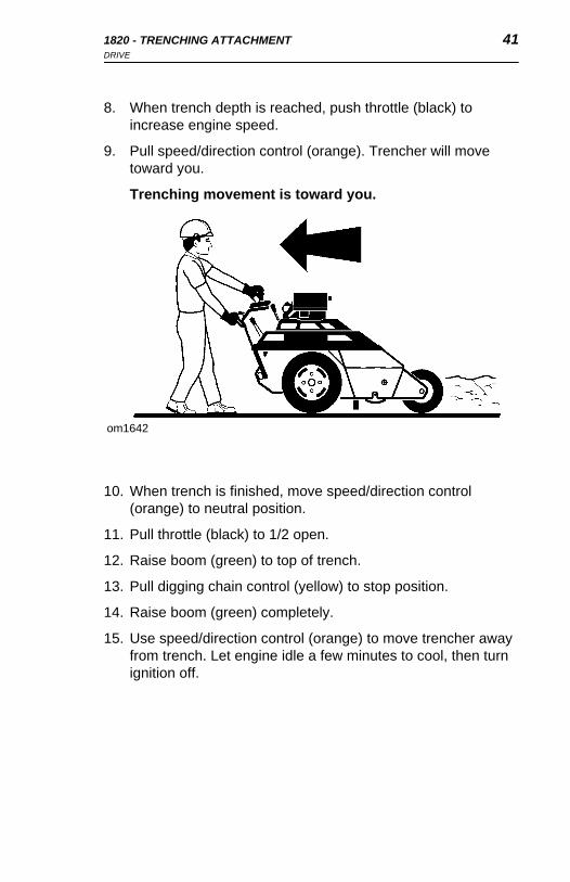
8. When trench depth is reached, push throttle (black) to increase engine speed.
9. Pull speed/direction control (orange). Trencher will move toward you.
Trenching movement is toward you.
10. When trench is finished, move speed/direction control (orange) to neutral position.
11. Pull throttle (black) to 1/2 open.
12. Raise boom (green) to top of trench.
13. Pull digging chain control (yellow) to stop position.
14. Raise boom (green) completely.
15. Use speed/direction control (orange) to move trencher away from trench. Let engine idle a few minutes to cool, then turn ignition off.
om1642
42 1820 - TRENCHING ATTACHMENTOPERATING TIPS
42 1820 - TRENCHING ATTACHMENTOPERATING TIPS
OPERATING TIPS
• Avoid digging with badly worn digging teeth. When replacing old teeth, maintain original tooth pattern. Use Ditch Witch replacement teeth for best trenching results.
• Operate engine at full throttle under load for most productive trenching. If soil conditions permit, operating in this range gives longer engine life and more efficient use of available engine horsepower.
• Use slower digging chain speed in hard soil. Use alligator chain in frozen or rocky soil.
• When beginning trench near a wall or fence, allow enough distance between boom and footings, drains, and cables.
• Use correct digging boom length. Shortest turn may be made with boom fully down.
• When cutting across asphalt roads, start trench in soil at edge of road and dig with shortest possible boom at full digging depth.
• For a clean trench floor, use optional trench cleaner.
• When straight trenching across a slope, it can be helpful to stake 4x4” wood beam parallel to intended course and just far enough from trench to guide downslope wheel.
• Trenching a straight line is easier with wheels turned slightly to auger side of machine.

1820 - DRILLING ATTACHMENT 43OPERATING TIPS
1820 - DRILLING ATTACHMENT 43OPERATING TIPS
DRILLING ATTACHMENTTurning shaft will kill you or
crush arm or leg. Stay away.
NOTICE: Keep everybody at least 10’ (3 m) away from drill pipe during operation. Do not straddle trench or drill pipe while drilling.
Jobsite hazards could cause death or serious injury. Use correct equipment and work methods. Use and maintain proper safety equipment.
NOTICE: Set up warning barriers and keep people away from equipment and jobsite while drilling.
Incorrect procedures could result in death, injury, or property damage. Learn to use equipment correctly.
Improper control function could cause death or serious injury. If control does not work as described in instructions, stop machine and have it serviced.
NOTICE: Do not tape or tie down switch or lever.
44 1820 - DRILLING ATTACHMENTDRILLING ATTACHMENT CONTROL DESCRIPTION
44 1820 - DRILLING ATTACHMENTDRILLING ATTACHMENT CONTROL DESCRIPTION
DRILLING ATTACHMENT CONTROL DESCRIPTION
Drilling Control
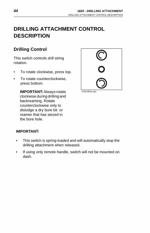
This switch controls drill string rotation.
• To rotate clockwise, press top.
• To rotate counterclockwise, press bottom.
IMPORTANT: Always rotate clockwise during drilling and backreaming. Rotate counterclockwise only to dislodge a dry bore bit or reamer that has siezed in the bore hole.
IMPORTANT:
• This switch is spring-loaded and will automatically stop the drilling attachment when released.
• If using only remote handle, switch will not be mounted on dash.
c00ic084a.eps
DRILLING ATTACHMENT CONTROL DESCRIPTION
Drilling Control
This switch controls drill string rotation.
• To rotate clockwise, press top.
• To rotate counterclockwise, press bottom.
IMPORTANT: Always rotate clockwise during drilling and backreaming. Rotate counterclockwise only to dislodge a dry bore bit or reamer that has siezed in the bore hole.
IMPORTANT:
• This switch is spring-loaded and will automatically stop the drilling attachment when released.
• If using only remote handle, switch will not be mounted on dash.
c00ic084a.eps
1820 - DRILLING ATTACHMENT 45PREPARE JOBSITE AND EQUIPMENT
1820 - DRILLING ATTACHMENT 45PREPARE JOBSITE AND EQUIPMENT
PREPARE JOBSITE AND EQUIPMENT
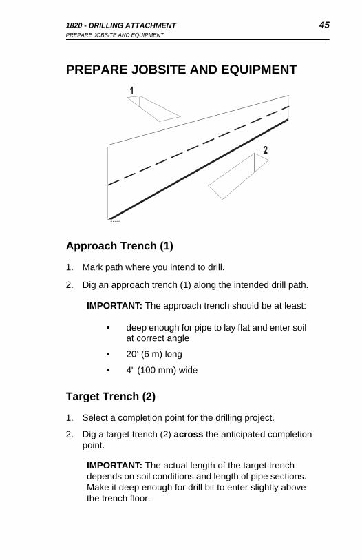
Approach Trench (1)
1. Mark path where you intend to drill.
2. Dig an approach trench (1) along the intended drill path.
Target Trench (2)
1. Select a completion point for the drilling project.
2. Dig a target trench (2) across the anticipated completion point.
IMPORTANT: The approach trench should be at least:
• deep enough for pipe to lay flat and enter soil at correct angle
• 20’ (6 m) long
• 4" (100 mm) wide
IMPORTANT: The actual length of the target trench depends on soil conditions and length of pipe sections. Make it deep enough for drill bit to enter slightly above the trench floor.
om0529h eps
1
2
PREPARE JOBSITE AND EQUIPMENT
Approach Trench (1)
1. Mark path where you intend to drill.
2. Dig an approach trench (1) along the intended drill path.
Target Trench (2)
1. Select a completion point for the drilling project.
2. Dig a target trench (2) across the anticipated completion point.
IMPORTANT: The approach trench should be at least:
• deep enough for pipe to lay flat and enter soil at correct angle
• 20’ (6 m) long
• 4" (100 mm) wide
IMPORTANT: The actual length of the target trench depends on soil conditions and length of pipe sections. Make it deep enough for drill bit to enter slightly above the trench floor.
om0529h eps
1
2

46 1820 - DRILLING ATTACHMENTPREPARE JOBSITE AND EQUIPMENT
46 1820 - DRILLING ATTACHMENTPREPARE JOBSITE AND EQUIPMENT
Drill Pipe and Equipment
1. Assemble at least 20’ (6 m), but not more than 30’ (9 m), of drill rod.
2. Install drill bit to the cutting end of the drill string.
3. Put drill string in approach trench.
4. Move tractor to the approach trench and align the drilling attachment with the intended bore path.
5. Turn off engine.
6. Attach drill string to drilling attachment.
NOTICE: More than 10-15’ (3-4.5 m) of drill rod out of the trench increases the tendency of drill rod to bend.
om0540h.eps

1820 - DRILLING ATTACHMENT 47DRILL
1820 - DRILLING ATTACHMENT 47DRILL
DRILL
1. Start tractor’s engine and begin clockwise (forward) rotation.
2. Slowly advance tractor while maintaining clockwise rotation.
EMERGENCY SHUTDOWN: Release drilling control and turn ignition switch to STOP.
NOTICE:
• Drilling too quickly causes bit to drift off course and may bend drill rod. After drill path is established, speed may be slightly increased.
• If drill rod starts to bend, stop forward movement of unit and back the unit slightly until rod straightens. Do not drill with bent rod.
• If drill rod hits an obstruction, rotate drill string counterclockwise to back up slightly.

48 1820 - DRILLING ATTACHMENTDRILL
48 1820 - DRILLING ATTACHMENTDRILL
Using Drill String Guide
Use drill string guide to align drill string as it enters the soil. When using drill string guide, follow these guidelines:
• Use only approvedDitch Witch drill string guide (p/n 179-737).
• Stand only on the left side of the approach trench.
• Keep drill string guide at least 3’ (1 m) behind bit.
• Use drill string guide to control only the first 5’ (1.5 m) of the bore path.
• After drilling 5’ (1.5 m), stop unit and remove drill string guide.
• Do not use drill string guide during backreaming or any time the drill string is being pulled back.
Turning shaft will kill you or crush arm or leg. Stay away.
NOTICE: Keep everybody at least 10’ (3 m) away from drill rod during operation. Do not straddle trench or drill rod while drilling.
om0342c.eps
1820 - DRILLING ATTACHMENT 49ADD ROD
1820 - DRILLING ATTACHMENT 49ADD ROD
ADD ROD
1. Stop drilling attachment.
2. Back up tractor 6" (150 mm) to loosen drill rod in ground.
3. Disconnect drill rod from drilling attachment.
4. Move tractor away from bore.
5. Add one drill rod to continue bore.
BACKREAM
After drill bit enters target trench, the bore hole may be enlarged by changing the drill bit to a backreamer and drawing it back through the initial bore.
1. Turn tractor ignition switch to STOP.
2. Replace drill bit with backreamer.
3. Start tractor engine and begin clockwise rotation.
4. Slowly back up tractor while maintaining rotation.
5. When backreamer exits the bore hole, stop rotation immediately.
IMPORTANT: Always rotate clockwise during backreaming. Rotate counterclockwise only to dislodge a dry bore bit or reamer that has siezed in the bore hole.
IMPORTANT:
• Do not try to increase hole size too much in one pass. Several passes using successively larger reamers will save wear on machine.
• During backreaming, keep drill string straight. Sharp bends in the drill rod at the motor coupling can cause rod failure.

50 1820 - DRILLING ATTACHMENTDISASSEMBLE JOINTS
50 1820 - DRILLING ATTACHMENTDISASSEMBLE JOINTS
DISASSEMBLE JOINTS
1. Press tab through hole in female side of joint using special tool or screwdriver.
2. Pull rods apart.
OPTIONAL EQUIPMENT
Drill Rod
Bent or damaged drill rod might break when being pushed. Replacement drill rod and connectors are available through your Ditch Witch dealer.
Bits and Backreamers
Bits and backreamers are available in a variety of sizes and types to match jobsite needs. Contact your Ditch Witch dealer for more information.

1820 - LUBRICATION 511820 - LUBRICATION 51
LUBRICATION
Proper lubrication and maintenance protects Ditch Witch equipment from damage and failure.
Use only recommended lubricants. Fill to capacities listed in SPECIFICATIONS.
Incorrect procedures could result in death, injury, or property damage. Learn to use equipment correctly.
NOTICES:
• Unless otherwise instructed, all service should be performed with engine shut off.
• Refer to engine manufacturer's manual for engine maintenance instructions.
• Before servicing equipment, lower digging boom to ground.
Recommended LubricantsAGMA-7 Worm gear lubricant matching American Gear Manufacturer’s
Association Compound #7
GEO Gasoline Engine Oil meeting API service classification SD
DEO Diesel Engine Oil (SAE 10W40) meeting API engine service classification SF/CD or CE
MPG Multipurpose grease
MPL Multipurpose lubricant 80W90
THF Tractor hydraulic fluid, similar to Phillips 66 HG, Mobilfluid 432, Chevron tractor hydraulic fluid, Texaco TDH oil, or equivalent

52 1820 - LUBRICATIONLUBRICATION SCHEDULE
52 1820 - LUBRICATIONLUBRICATION SCHEDULE
LUBRICATION SCHEDULE
Gasoline engine oilDiesel engine oil
Multipurpose lubricant (MPL) 80W90
Multipurpose lubricant (AGMA-7)
Multipurpose grease
Tractor hydraulic fluid (THF)
LUBRICATION SCHEDULE
Gasoline engine oilDiesel engine oil
Multipurpose lubricant (MPL) 80W90
Multipurpose lubricant (AGMA-7)
Multipurpose grease
Tractor hydraulic fluid (THF)

1820 - LUBRICATION 53LUBRICATION SCHEDULE
1820 - LUBRICATION 53LUBRICATION SCHEDULE
Interval Task Page
10 hours Check engine oil 54
Check hydraulic oil 55
20 hours Change engine oil (initial) 54
50 hours Lube pivot tube 57
Lube trail wheel 57
Check axle reducer box oil 58
Change axle reducer box (initial) 58
Change headshaft reducer box (initial) 59
75 hours Change engine oil and filter (diesel) 54
100 hours Change engine oil and filter (gas) 54
250 hours Change hydraulic oil and filter 55
Lube cross and bearings 57
500 hours Change axle reducer box 58
Change headshaft reducer box 59
54 1820 - LUBRICATIONENGINE OIL
54 1820 - LUBRICATIONENGINE OIL
ENGINE OIL
Check Oil
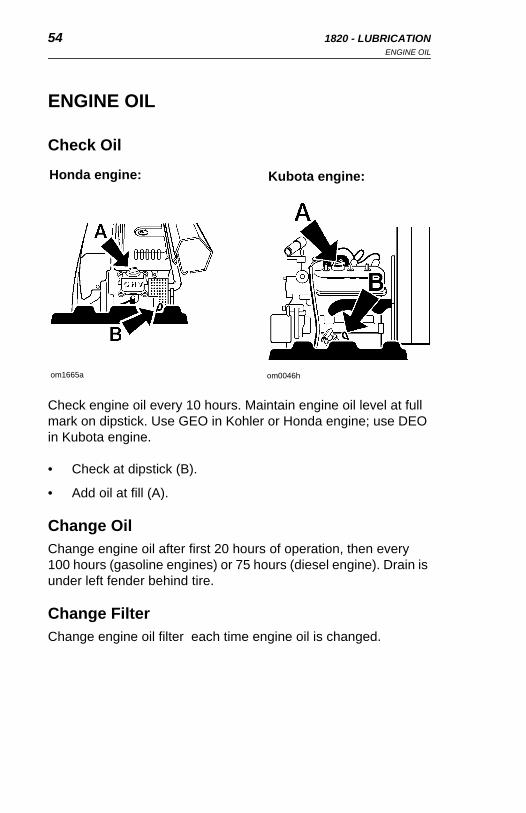
Check engine oil every 10 hours. Maintain engine oil level at full mark on dipstick. Use GEO in Kohler or Honda engine; use DEO in Kubota engine.
• Check at dipstick (B).
• Add oil at fill (A).
Change OilChange engine oil after first 20 hours of operation, then every 100 hours (gasoline engines) or 75 hours (diesel engine). Drain is under left fender behind tire.
Change FilterChange engine oil filter each time engine oil is changed.
Honda engine:
om1665a om0046h
Kubota engine:
ENGINE OIL
Check Oil
Check engine oil every 10 hours. Maintain engine oil level at full mark on dipstick. Use GEO in Kohler or Honda engine; use DEO in Kubota engine.
• Check at dipstick (B).
• Add oil at fill (A).
Change OilChange engine oil after first 20 hours of operation, then every 100 hours (gasoline engines) or 75 hours (diesel engine). Drain is under left fender behind tire.
Change FilterChange engine oil filter each time engine oil is changed.
Honda engine:
om1665a om0046h
Kubota engine:

1820 - LUBRICATION 55HYDRAULIC OIL
1820 - LUBRICATION 55HYDRAULIC OIL
HYDRAULIC OIL
Check Hydraulic OilCheck hydraulic oil every 10 hours.
• Raise boom fully and turn rear wheels to the left (D).
• Clean cap and tube before removing dipstick (A).
• Refill to full mark with THF.
Change Hydraulic Oil and FilterChange hydraulic oil and filter every 250 hours.
• Drain at plug (C).
• Fill with 5.5 gal (21 L) THF at dipstick (A).
• Replace hydraulic oil filter (B).
om1033.pcx
om1670

56 1820 - LUBRICATIONHYDRAULIC OIL
56 1820 - LUBRICATIONHYDRAULIC OIL
Fluid or air under pressure could pierce skin and cause injury or death. Stay away.
NOTICE: Escaping pressurized fluid can cause injury or pierce skin and poison.
• Before disconnecting lines, turn engine off and operate system controls to relieve pressure.
• Before using system, check that all connections are tight and all lines are undamaged.
• Fluid leaks can be hard to detect. Use a piece of cardboard or wood, rather than hands, to search for leaks.
• Wear protective clothing and eye protection.
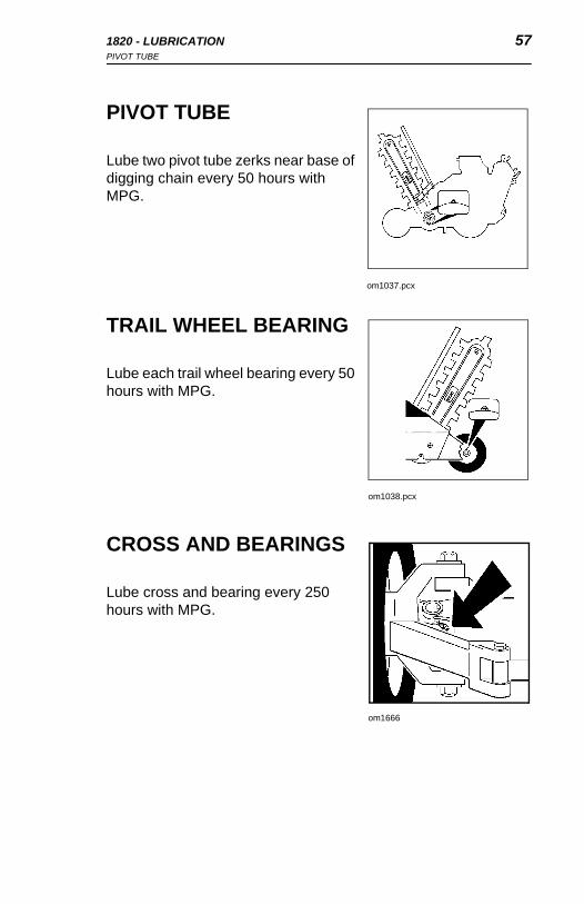
1820 - LUBRICATION 57PIVOT TUBE
1820 - LUBRICATION 57PIVOT TUBE
PIVOT TUBE
Lube two pivot tube zerks near base of digging chain every 50 hours with MPG.
TRAIL WHEEL BEARING
Lube each trail wheel bearing every 50 hours with MPG.
CROSS AND BEARINGS
Lube cross and bearing every 250 hours with MPG.
om1037.pcx
om1038.pcx
om1666
PIVOT TUBE
Lube two pivot tube zerks near base of digging chain every 50 hours with MPG.
TRAIL WHEEL BEARING
Lube each trail wheel bearing every 50 hours with MPG.
CROSS AND BEARINGS
Lube cross and bearing every 250 hours with MPG.
om1037.pcx
om1038.pcx
om1666

58 1820 - LUBRICATIONREDUCER BOXES
58 1820 - LUBRICATIONREDUCER BOXES
REDUCER BOXES
Axle Reducer BoxCheck axle reducer box oil every 50 hours.
Change axle reducer box oil after first 50 hours of operation and then every 500 hours.
• Turn tires fully to left.
• Remove fill plug (A) through access hole.
• Remove drain plug (B).
• When drained, clean and replace plug.
• Refill with 2.5 pints (1.2 L) AGMA-7.
om1036.pcx

1820 - LUBRICATION 59REDUCER BOXES
1820 - LUBRICATION 59REDUCER BOXES
Headshaft Reducer BoxCheck headshaft reducer box oil after every 500 hours.
Change headshaft reducer box oil after first 50 hours of operation and then every 500 hours.
• Remove gear box fill plug (B) through access hole. Oil should be at bottom of fill opening threads.
• Drain at plug (A).
• Refill gear box with 2.5 pint (1.2 L) MPL.
• Do not overfill.
om1039.pcx

60 1820 - LUBRICATION 60 1820 - LUBRICATION
1820 - MAINTENANCE 611820 - MAINTENANCE 61
MAINTENANCE
See ENGINE MANUFACTURER'S GUIDE for further maintenance instructions.
Incorrect procedures could result in death, injury, or property damage. Learn to use equipment correctly.
NOTICES:
• Unless otherwise instructed, all service should be performed with engine shut off.
• Before servicing equipment, lower digging boom to ground.
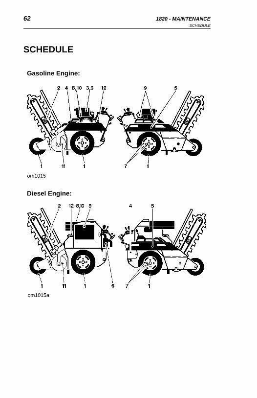
62 1820 - MAINTENANCESCHEDULE
62 1820 - MAINTENANCESCHEDULE
SCHEDULE
Diesel Engine:
Gasoline Engine:
om1015
om1015a
SCHEDULE
Diesel Engine:
Gasoline Engine:
om1015
om1015a
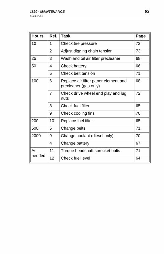
1820 - MAINTENANCE 63SCHEDULE
1820 - MAINTENANCE 63SCHEDULE
Hours Ref. Task Page
10 1 Check tire pressure 72
2 Adjust digging chain tension 73
25 3 Wash and oil air filter precleaner 68
50 4 Check battery 66
5 Check belt tension 71
100 6 Replace air filter paper element and precleaner (gas only)
68
7 Check drive wheel end play and lug nuts
72
8 Check fuel filter 65
9 Check cooling fins 70
200 10 Replace fuel filter 65
500 5 Change belts 71
2000 9 Change coolant (diesel only) 70
4 Change battery 67
As needed
11 Torque headshaft sprocket bolts 71
12 Check fuel level 64
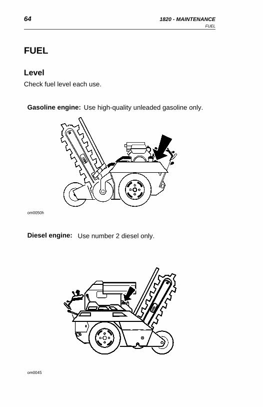
64 1820 - MAINTENANCEFUEL
64 1820 - MAINTENANCEFUEL
FUEL
LevelCheck fuel level each use.
Gasoline engine:
om0050h
Diesel engine:
om0045
Use high-quality unleaded gasoline only.
Use number 2 diesel only.
FUEL
LevelCheck fuel level each use.
Gasoline engine:
om0050h
Diesel engine:
om0045
Use high-quality unleaded gasoline only.
Use number 2 diesel only.

1820 - MAINTENANCE 65FUEL
1820 - MAINTENANCE 65FUEL
FilterCheck fuel filter for blockage every 100 hours. Replace blocked filters.
Replace fuel filter every 200 hours.
Gasoline engine:
Diesel engine:
om0041h
om0049h
FilterCheck fuel filter for blockage every 100 hours. Replace blocked filters.
Replace fuel filter every 200 hours.
Gasoline engine:
Diesel engine:
om0041h
om0049h

66 1820 - MAINTENANCEBATTERY
66 1820 - MAINTENANCEBATTERY
BATTERY
Battery acid may cause burns. Avoid contact.
Hot parts may cause burns. Do not touch until cool.
CheckCheck battery fluid level every 50 hours. Fill cavity with enough distilled water to cover plates. Do not overfill.
Keep battery case and terminals clean. Remove corrosion from terminals with wire brush. Wash terminals with baking soda and water solution. Apply coat of grease to cable clamps after cleaning.

1820 - MAINTENANCE 67BATTERY
1820 - MAINTENANCE 67BATTERY
ChargeIn cold weather, check battery charge frequently. If water is added during freezing weather, charge battery immediately.
If battery will not hold charge, replace with one meeting requirements listed in SPECIFICATIONS.
ChangeReplace battery every 2000 hours.
Gasoline engine:
om1018.pcx
Diesel engine:
om0044h

68 1820 - MAINTENANCEAIR FILTER
68 1820 - MAINTENANCEAIR FILTER
AIR FILTER
Gasoline EngineClean every 25 hours.
• Clean and oil air filter precleaner.
• Clean paper element.
• Clean inside of air filter housing with damp cloth and allow to dry.
• Inspect parts and tighten or replace if necessary.
Replace air filter precleaner and paper element every 100 hours.
1. Foam rubber precleaner
2. Machine screws
3. Rubber gasket
4. Paper air filter element
5. Rubber gasket
6. Cover
7. Wing bolt
om1012.pcx
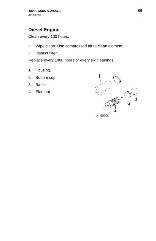
1820 - MAINTENANCE 69AIR FILTER
1820 - MAINTENANCE 69AIR FILTER
Diesel EngineClean every 100 hours.
• Wipe clean. Use compressed air to clean element.
• Inspect filter.
Replace every 1000 hours or every six cleanings.
1. Housing.
2. Bottom cup
3. Baffle
4. Element
om0000c
Diesel EngineClean every 100 hours.
• Wipe clean. Use compressed air to clean element.
• Inspect filter.
Replace every 1000 hours or every six cleanings.
1. Housing.
2. Bottom cup
3. Baffle
4. Element
om0000c

70 1820 - MAINTENANCEAIR FILTER
70 1820 - MAINTENANCEAIR FILTER
COOLING SYSTEM
Cooling FinsClean cooling fins on cylinder head and barrel every 100 hours. On diesel engines, check radiator for dirt in fins.
Radiator (Diesel engine)Change coolant every 2000 hours. Check at overflow tank (2). Drain at plug (3). Fill with antifreeze or coolant at fill (1) until tank is full and overflow tank to half-full.
om1022.pcx
om0042h
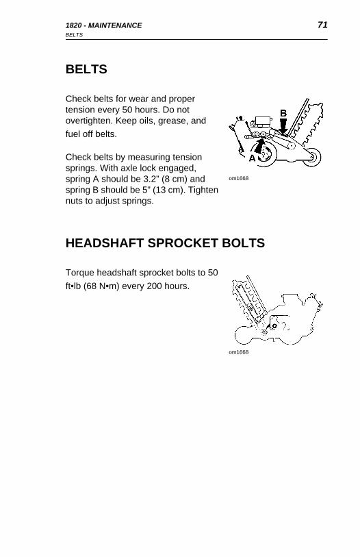
1820 - MAINTENANCE 71BELTS
1820 - MAINTENANCE 71BELTS
BELTS
Check belts for wear and proper tension every 50 hours. Do not overtighten. Keep oils, grease, and fuel off belts.
Check belts by measuring tension springs. With axle lock engaged, spring A should be 3.2” (8 cm) and spring B should be 5” (13 cm). Tighten nuts to adjust springs.
HEADSHAFT SPROCKET BOLTS
Torque headshaft sprocket bolts to 50 ft•lb (68 N•m) every 200 hours.
om1668
om1668

72 1820 - MAINTENANCEWHEELS AND TIRES
72 1820 - MAINTENANCEWHEELS AND TIRES
WHEELS AND TIRES
Tire PressureCheck tires with gauge before operating machine.
• Drive tires (A) recommended maximum pressure is 22 psi (1.5 bar).
• Trail tire (B) recommended pressure is 32 psi (2.2 bar).
Drive WheelsCheck for loose drive wheels every 100 hours.
• Block wheels.
• Shake drive wheels.
• If loose, remove roll pin (C) and tighten castle nut (A). Do not overtighten; wheels should turn smoothly.
• Replace roll pin (C).
• Torque lug nuts (B) to 85 ft•lb (115 N•m).
om1016.pcx
om1024.pcx
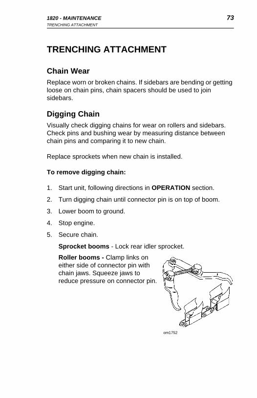
1820 - MAINTENANCE 73TRENCHING ATTACHMENT
1820 - MAINTENANCE 73TRENCHING ATTACHMENT
TRENCHING ATTACHMENT
Chain WearReplace worn or broken chains. If sidebars are bending or getting loose on chain pins, chain spacers should be used to join sidebars.
Digging ChainVisually check digging chains for wear on rollers and sidebars. Check pins and bushing wear by measuring distance between chain pins and comparing it to new chain.
Replace sprockets when new chain is installed.
To remove digging chain:
1. Start unit, following directions in OPERATION section.
2. Turn digging chain until connector pin is on top of boom.
3. Lower boom to ground.
4. Stop engine.
5. Secure chain.
Sprocket booms - Lock rear idler sprocket.
Roller booms - Clamp links on either side of connector pin with chain jaws. Squeeze jaws to reduce pressure on connector pin.
om1752

74 1820 - MAINTENANCETRENCHING ATTACHMENT
74 1820 - MAINTENANCETRENCHING ATTACHMENT
6. Loop cable through links nearest connector pin.
Incorrect procedures could result in death, injury, or property damage. Learn how to use equipment correctly.
7. Turn tension bolts counterclockwise to release tension on digging chain.
8. Stand clear of chain. Do not stand behind boom. Keep feet from under boom.
9. Remove pin from connector pin and drive pin out of link.
10. Unclamp links (roller boom). Slowly release cable and lower chain to ground.
om1744

1820 - MAINTENANCE 75TRENCHING ATTACHMENT
1820 - MAINTENANCE 75TRENCHING ATTACHMENT
To install digging chain:
1. Lay digging chain on ground with teeth down and pointed toward unit. Loop cable through end links.
2. Start unit.
3. Back unit up until digging chain extends past headshaft about one foot.
4. Lower boom to horizontal position.
5. Stop engine.
6. Secure chain on sprocket booms by locking rear idler sprocket.
7. Pull rear end of chain over tail sprocket or roller. Pull cable until chain is in place on boom.
8. Attach chain jaws to end links and bring links into place.
9. Install connector pin and lock key.
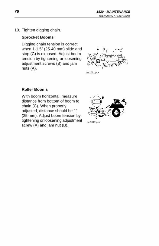
76 1820 - MAINTENANCETRENCHING ATTACHMENT
76 1820 - MAINTENANCETRENCHING ATTACHMENT
10. Tighten digging chain.
Sprocket BoomsDigging chain tension is correct when 1-1.5” (25-40 mm) slide and stop (C) is exposed. Adjust boom tension by tightening or loosening adjustment screws (B) and jam nuts (A).
Roller BoomsWith boom horizontal, measure distance from bottom of boom to chain (C). When properly adjusted, distance should be 1” (25 mm). Adjust boom tension by tightening or loosening adjustment screw (A) and jam nut (B).
om1031.pcx
om1017.pcx

1820 - MAINTENANCE 77TRENCHING ATTACHMENT
1820 - MAINTENANCE 77TRENCHING ATTACHMENT
Digging TeethDigging teeth should be replaced with new Ditch Witch teeth. When replacing teeth, maintain original tooth pattern.
Each unit is equipped with a standard tooth configuration. Depending on soil conditions and type of chain, a different configuration might produce better results. Contact your authorized Ditch Witch dealer for more information about digging teeth patterns.
Alligator chain bits, like teeth, wear out. When tungsten cap or insert is gone, bit will wear quickly. Replace it before bit adapter is damaged.
Bits must rotate freely in bit holders. Clean chain and check bits for free rotation after each use. If any bit does not rotate, it will wear unevenly and quickly.

78 1820 - MAINTENANCE 78 1820 - MAINTENANCE
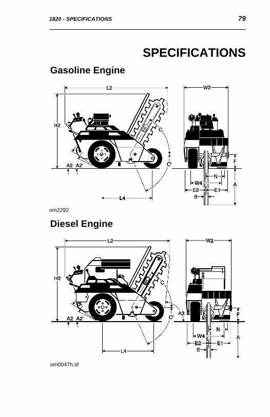
1820 - SPECIFICATIONS 791820 - SPECIFICATIONS 79
SPECIFICATIONS
om0047h.tif
om2292
Gasoline Engine
Diesel Engine
SPECIFICATIONS
om0047h.tif
om2292
Gasoline Engine
Diesel Engine

80 1820 - SPECIFICATIONS 80 1820 - SPECIFICATIONS
DIMENSIONS*: U.S. METRIC
A Trench depth 48 in 1.2 m
B Trench width 3.25-16 in 85-405 mm
C Boom travel up 60° 60°
C' Boom travel down 60° 60°
F Headshaft height 11 in 280 mm
L Length-transport 81 in 2.6 m
W Width-transport 35.6 in 905 mm
H Height-transport** 63 in 1.6 m
Kubota 66.5in
W Tread 27 in 685 mm
A Angle of departure 84° 84°
L Wheelbase 43 in 1090 mm
E Centerline trench to outside edge machine, left
16.25 in 415 mm
E Centerline trench to outside edge machine, right
19.3 in 90 mm
A Angle of approach 32° 32°
A'. Angle of approach w/boring attachment 17° 17°
Spoil discharge reach 13.2 in 335 mm
*Dimensions are based on narrow tread and 8” (203 mm) pivot and gas engine.
**Standard boom: refer to chart for recommended depth/width combinations.
GENERAL:
Ditch Witch Model 1820, self-propelled, non-riding, hydraulically steered, two-wheel drive, rigid frame, chain-type trencher.

1820 - SPECIFICATIONS 811820 - SPECIFICATIONS 81
OPERATION: U.S. METRIC
Vehicle speeds
Maximum transit forward 142 fpm 43 m/min
Maximum transit reverse 86 fpm 26 m/min
Digging chain speed @ 207 rpm 290 fpm 88 m/min
Tire steering angle
Inside tire 28.5° 28.5°
Outside tire 23° 23°
Vehicle clearance circle (SAE) 20.7 ft 6.3 m
Spoil handling
Auger-type Single, open end
Auger-size 18.75 in OD x 1.5 in ID x 11.5 in long
476 mm OD x 40 mm ID x 290 mm long
Trench cleaner type Mechanical
Trench cleaner size 4 - 16 in 100-405 mm
Operating weight (based on roller boom and narrow digging chain)
Gasoline engines 1300 lb 590 kg
Diesel engine 1760 lb 798 kg
TRENCH SIZES:
DEPTH WIDTH
U.S METRIC U.S. METRIC
24 inch 610 mm 16 ** inch 405 mm
24 inch 610 mm 14 ** inch 355 mm
30 inch 760 mm 12 * inch 305 mm
36 inch 915 mm 10 * inch 255 mm
48 inch 1220 mm 8 inch 205 mm
48 inch 1220 mm 6 inch 150 mm
48 inch 1220 mm 4 inch 100 mm
48 inch 1220 mm 3.25 inch 85 mm
* With 12” pivot option

82 1820 - SPECIFICATIONS 82 1820 - SPECIFICATIONS
** With 16” pivot option
POWER OPTIONS: U.S. METRIC
Engine (Honda GX610)
Fuel — Gasoline
Cooling medium — Air
Number of cylinders — 2
Displacement 37.5 in3 614 cm3
Bore 3.03 in 77 mm
Stroke 2.60 in 66 mm
Manufacturers net power rating (per SAE J1349)
18 hp 13.4 kW
Rated speed 3600 rpm* 3600 rpm*
Maximum torque @ 2500 rpm 31.8 ft•lb 43.1 N•m
Max. tilt angle** All directions 20° 20°
Engine (Kubota D722-E)
Fuel — Diesel
Cooling medium — Water
Number of cylinders — 3
Displacement 43.88 in3 719 cm3
Bore 2.64 in 67 mm
Stroke 2.68 in 68 mm
Engine manufacturers gross power rating @ 3600 rpm
18.8 hp 14.0 kW
Maximum governed speed as installed (no load)*
3200 rpm* 3200 rpm*
Flywheel power @ 3000 rpm (full load)
17.6 hp 13.1 kW
Fuel consumption @ 3000 rpm 1.0 gph 3.8 L/h
Max. tilt angle** All directions 20° 20°
*Product support may be void if engine is run above "Maximum governed speed as installed (no load)."

1820 - SPECIFICATIONS 831820 - SPECIFICATIONS 83
**Exceeding this operating angle will cause engine damage. This DOES NOT IMPLY machine is stable to maximum angle of engine operation.
POWER TRAIN:
Ground Drive Transmission
(Drive and Dig) Infinitely variable from zero to maximum, enclosed gear box to axle, speed and direction controlled with single lever
Clutch Mechanical, hand operated, spring loaded with tension roller for belt drive
Belt 2 strand 3V "Power Band"
Tires - drive 23 x 8.50 - 12
23 x 10.50 - 12 (option)
Tire - trail 16 x 6.50 - 8
Trencher Drive Mechanical - Belt drive to enclosed reduction drive, headshaft
Belt 3 strand "Power Band"
Digging chain 33,000 lb (15000 kg) test
Chain drive sprocket Forged and tempered
Digging tools Bolt-on cup teeth with hard surfaced edge of tungsten carbide
Spoil Handling Drive Mechanical, attached to and rotates with headshaft
HYDRAULIC SYSTEM: U.S. METRIC
Drive pump capacity @ 3200 rpm 12.6 gpm 48 L/min
Filtration Return flow, 10 micron nominal
Hydraulic motor, drive
Torque @ 2000 psi (138 bar) and 12.6 gpm (48 L/min)
1347 in•lb. 152 N•m
Speed @ 2000 psi (138 bar) and 12.6 gpm (48 L/min)
542 rpm 542 rpm
Displacement/rev 4.9 in3 80 cm3
Pump capacity, drilling @ 3200 rpm 5 gpm 19 L/min
Hydraulic motor, drilling

84 1820 - SPECIFICATIONS 84 1820 - SPECIFICATIONS
Torque @ 2000 psi (138 bar) and 5 gpm (19 L/min)
3088 in•lb 349 N•m
Speed @ 2000 psi (138 bar) and 5 gpm (19 L/min)
78 rpm 78 rpm
Displacement/rev 11.9 in3 195 cm3
Bidirectional
Hydraulic cylinders:
Function Boom lift, steering
Type Double acting
STEERING:
Type — Power on drive axle, lever controlled

1820 - SPECIFICATIONS 851820 - SPECIFICATIONS 85
FLUID CAPACITIES: U.S. METRIC
Fuel tank
Gasoline 5.4 gal 20.4 L
Diesel 6.5 gal 24.6 L
Engine oil:
Honda 1.5 pt 1.4 L
Kubota 0.84 gal 3.2 L
Hydraulic reservoir 5.5 gal 20.8 L
Hydraulic system 6.25 gal 23.7 L
Headshaft reducer oil 2.5 pt 1.2 L
Axle reducer oil 2.5 pt 1.2 L
BATTERY:
Group 26R, 12-volt, top-post; SAE Reserve Capacity 60-80 min.; SAE cold crank 450 amps.
VIBRATION LEVEL
Vibration at the operator's hand during normal operation is 3.25 m/s2.
NOISE LEVEL
Operator 89 dBA sound pressure per ISO 6394
Exterior 100 dBA sound power per ISO 6393
Specifications are called out according to SAE recommended procedures. Specifications are general and subject to change without notice. If exact measurements are required, equipment should be weighed and measured. Due to selected options, delivered equipment may not necessarily match that described.

86 1820 - SPECIFICATIONS 86 1820 - SPECIFICATIONS
1820 - WARRANTY 871820 - WARRANTY 87
WARRANTY
Ditch Witch Equipment and PartsLimited Warranty Policy
Subject to the limitations and exclusions herein, free replacement parts will be provided at any authorized Ditch Witch dealership for any Ditch Witch equipment or parts manufactured by The Charles Machine Works, Inc. (CMW) that fail due to a defect in material or workmanship within one (1) year of first commercial use (Exception: 2 years for all SK500 attachments). Free labor will be provided at any authorized Ditch Witch dealership for installation of parts under this warranty during the first year following initial commercial use of the serial-numbered Ditch Witch equipment on which it is installed.
Exclusions from Product Warranty• Wear-related failure of parts subject to ground contact including, but not limited
to, digging teeth, digging chains, sprockets, backhoe buckets, plow blades, drill pipe, drill bits, backreamers, and swivels.
• All incidental or consequential damages.• All defects, damages, or injuries caused by misuse, abuse, improper
installation, alteration, neglect, or uses other than those for which products were intended.
• All defects, damages, or injuries caused by improper training, operation, or servicing of products in a manner inconsistent with manufacturer’s recommendations.
• All engines and engine accessories (these are covered by original manufacturer’s warranty).
• Tires, belts, and other parts which may be subject to another manufacturer’s warranty (such warranty will be available to purchaser).
• All implied warranties not expressly stated herein, including any warranty of fitness for a particular purpose and merchantability.
IF THE PRODUCTS ARE PURCHASED FOR COMMERCIAL PURPOSES AS DEFINED BY THE UNIFORM COMMERCIAL CODE, THEN THERE ARE NO WARRANTIES WHICH EXTEND BEYOND THE FACE HEREOF AND THERE ARE NO IMPLIED WARRANTIES OF ANY KIND WHICH EXTEND TO A COMMERCIAL BUYER. ALL OTHER PROVISIONS OF THIS LIMITED WARRANTY APPLY INCLUDING THE DUTIES IMPOSED.

88 1820 - WARRANTY 88 1820 - WARRANTY
Ditch Witch products have been tested to deliver acceptable performance in most conditions. This does not imply they will deliver acceptable performance in all conditions. Therefore, to assure suitability, products should be operated under anticipated working conditions prior to purchase.
Defects will be determined by an inspection within thirty (30) days of the date of failure of the product or part by CMW or its authorized dealer. CMW will provide the location of its inspection facilities or its nearest authorized dealer upon inquiry. CMW reserves the right to supply remanufactured replacements parts under this warranty as it deems appropriate.
Extended warranties are available upon request from your local Ditch Witch dealer or CMW.
Some states do not allow exclusion or limitation of incidental or consequential damages, so above limitation of exclusion may not apply. Further, some states do not allow exclusion of or limitation of how long an implied warranty lasts, so the above limitation may not apply. This limited warranty gives product owner specific legal rights and the product owner may also have other rights which vary from state to state.
For information regarding this limited warranty, contact CMW’s Product Support department, P.O. Box 66, Perry, OK 73077-0066, or contact your local Ditch Witch dealer.
First version: 1/91; Latest version: 1/03


1820 - 911820 - 91