rt level combinational blocks paolo prinetto politecnico di torino (italy) university of illinois at...
TRANSCRIPT

RT level RT level combinational combinational
blocksblocks
RT level RT level combinational combinational
blocksblocks
Paolo PRINETTOPolitecnico di Torino (Italy)
University of Illinois at Chicago, IL (USA)
[email protected] [email protected]
www.testgroup.polito.it
Lecture
5.1

2 5.1
Goal
This lecture presents the set of functional blocks that are usually considered to be “elementary” or “basic” at the RT level.

3 5.1
Prerequisites
Lecture 3.3

4 5.1
Homework
No particular homework is foreseen

5 5.1
Further readings
Students interested in making a reference to a text book on the arguments covered in this lecture can refer, for instance, to:
M. Morris Mano, C.R.Kime: “Logic and Computer Design Fundamentals,” 2nd edition updatedPrentice Hall, Upple Saddle River, NJ (USA), 2001, (chapter 3, pp. 111-148 )

6 5.1
Elementary functional blocksElementary functional blocks
MultiplexerMultiplexer
Adder-Adder-SubtracterSubtracter DecoderDecoder
EncoderEncoder
ComparatorComparatorROMROM
ALUALU
MultiplierMultiplier
1’s counter1’s counterI/O interfacesI/O interfaces

7 5.1
AddersAdders
We shall consider:
half adder
full adder
adder-subtracter

8 5.1
Half-Adder
A half-adder has:
2 inputs Ai, Bi
2 outputs Si and Ci+1
and computes the binary sum of the 2 input bits, providing:
the sum Si
the carry Ci+1

9 5.1
Si = Ai Bi
Ci+1 = Ai Bi
AAii B Bii
CCi+1 i+1 SSii

10 5.1
Full-Adder
A full-adder has:
3 inputs Ai, Bi and Ci
2 outputs Si and Ci+1
and computes the binary sum of the 3 input bits, providing:
the sum Si
the carry Ci+1

11 5.1
Si = Ai Bi Ci
Ci+1 = Ai Bi + Ai Ci + Bi Ci =
= Ai Bi + ( Ai Bi ) Ci
AAii B Bi i CCii
CCi+1 i+1 SSii

12 5.1
Adder-subtracterAdder-subtracter
An adder-subtracter is a combinational block capable of adding/subtracting two n-bits inputs operands, detecting overflow conditions. It has
2 n-bits data inputs, both labeled from n-1 to 0
1 control input to select one of the two operations
1 n-bits data output
1 control output asserted when an overflow condition is occurred.

13 5.1
Adder-subtracter Adder-subtracter (cont’d)
FUNC(n-1 downto 0)
A(n-1 downto 0)
B(n-1 downto 0)
ADD/~SUB
OVFL
Symbol

14 5.1
Elementary functional blocksElementary functional blocks
Adder-Adder-SubtracterSubtracter DecoderDecoder
EncoderEncoder
ComparatorComparatorROMROM
ALUALU
MultiplierMultiplier
1’s counter1’s counterI/O interfacesI/O interfaces
MultiplexerMultiplexer

15 5.1
MultiplexerMultiplexer
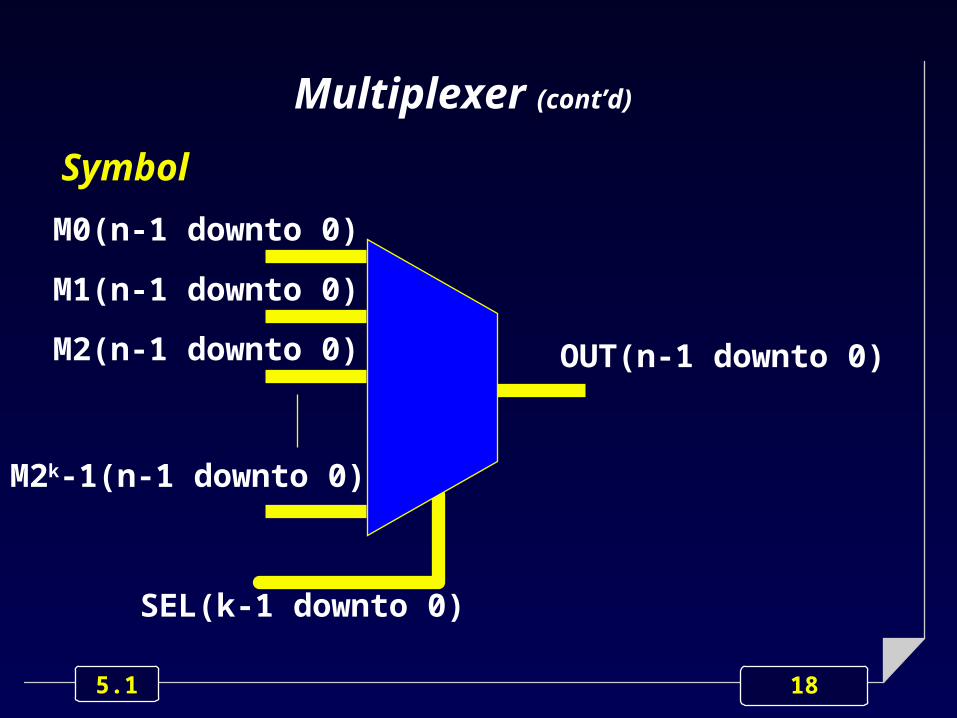
A multiplexer is a combinational block capable of forcing its output to the current value of one of its inputs, according to the values of some control signals.
Each input can be either a single wire or a bus.

16 5.1
MultiplexerMultiplexer
A multiplexer has:
2k data inputs, labeled from 2k-1 to 0
k control inputs
1 data output.
k 22kk-1 2-1 2kk-2 2 1 0-2 2 1 0MUXMUX
…
It gets the value It gets the value present on the input present on the input
labeled labeled 2 2 ii, where, where i i ((0 0 i i k-1k-1) is the ) is the
binary number present binary number present on the control inputs.on the control inputs.

17 5.1
OUT
SEL(k-1 downto 0)
Multiplexer (cont'd)
Symbol
IN(2k-1 downto 0)
18 5.1
Multiplexer (cont’d)
Symbol
M0(n-1 downto 0)
OUT(n-1 downto 0)
M1(n-1 downto 0)
M2(n-1 downto 0)
M2k-1(n-1 downto 0)
SEL(k-1 downto 0)

19 5.1
Elementary functional blocksElementary functional blocks
MultiplexerMultiplexer
Adder-Adder-SubtracterSubtracter DecoderDecoder
EncoderEncoder
ComparatorComparatorROMROM
ALUALU
MultiplierMultiplier
1’s counter1’s counterI/O interfacesI/O interfaces

20 5.1
DecoderDecoder
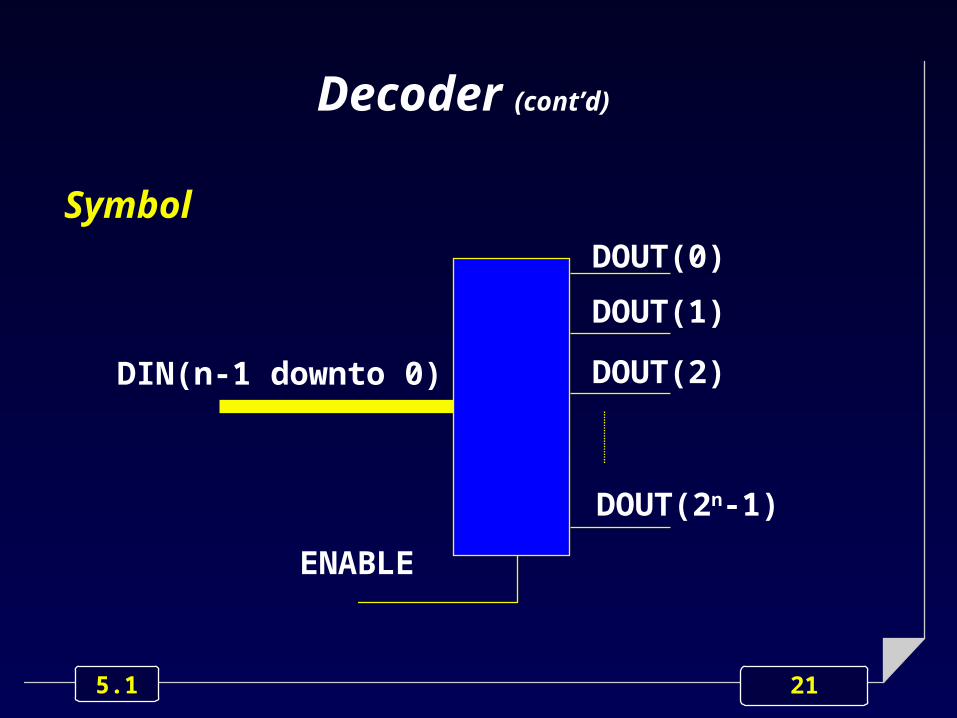
A decoder k 2k has:
1 n-bit data input
2 n outputs, labeled from 0 to 2 n-1
1 enable.
When enabled, just the output labeled 2 j is active, where j is the value present on the data input.
When disabled, no output is active.
21 5.1
Decoder (cont’d)
SymbolDOUT(0)
DIN(n-1 downto 0)
ENABLE
DOUT(1)
DOUT(2)
DOUT(2n-1)

22 5.1
Elementary functional blocksElementary functional blocks
MultiplexerMultiplexer
Adder-Adder-SubtracterSubtracter DecoderDecoder
EncoderEncoder
ComparatorComparatorROMROM
ALUALU
MultiplierMultiplier
1’s counter1’s counterI/O interfacesI/O interfaces

23 5.1
Priority EncoderPriority Encoder
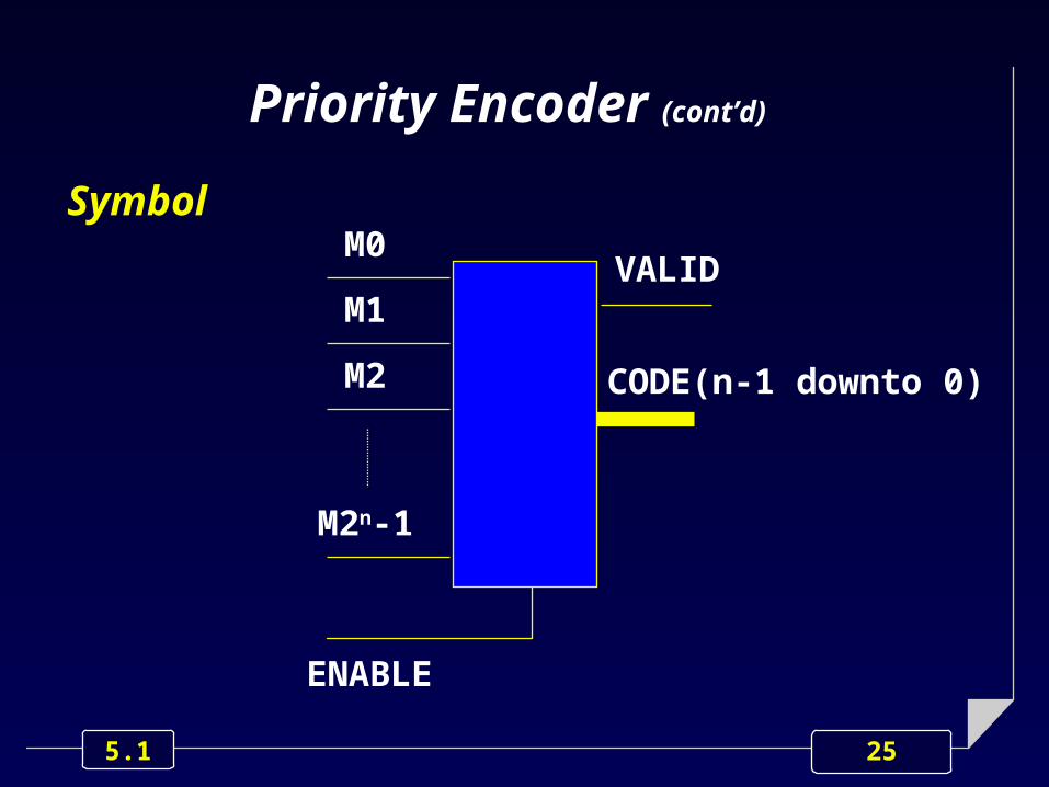
A priority encoder has:
2k inputs, labeled from 0 to 2k-1 (each input is assigned a fixed priority)
k outputs
1 “data valid” output
1 enable.

24 5.1
Priority Encoder Priority Encoder (cont’d)(cont’d)
When enabled:
the outputs get the value j , where j is the label of the highest priority asserted input
the “data valid” output is asserted.
When disabled or when no input is asserted:
the “data valid” output is not asserted.
25 5.1
M0
CODE(n-1 downto 0)
ENABLE
M1
M2
M2n-1
Priority Encoder (cont’d)
VALID
Symbol

26 5.1
Elementary functional blocksElementary functional blocks
MultiplexerMultiplexer
Adder-Adder-SubtracterSubtracter DecoderDecoder
EncoderEncoder
ComparatorComparatorROMROM
ALUALU
MultiplierMultiplier
1’s counter1’s counterI/O interfacesI/O interfaces

27 5.1
ComparatorComparator
A comparator gets 2 n-bit binary numbers:
A(n-1 downto 0) B(n-1 downto 0)
and provides in output the result of the comparison between A and B.
A control input UM/~2C specifies whether the input operands are unsigned or signed, respectively.

28 5.1
Comparator (cont’d)
AA
BB
AeqBAeqB
AneBAneB
AltBAltB
AgtBAgtB
AleBAleB
AgeBAgeB
Symbol
B(n-1 downto 0)
A(n-1 downto 0)
UM/~2CSel

29 5.1
Elementary functional blocksElementary functional blocks
MultiplexerMultiplexer
Adder-Adder-SubtracterSubtracter DecoderDecoder
EncoderEncoder
ComparatorComparatorROMROM
ALUALU
MultiplierMultiplier
1’s counter1’s counterI/O interfacesI/O interfaces

30 5.1
Counter of 1’s occurrencesCounter of 1’s occurrences
A counter of 1’s occurrences has:
1 n-bit data input
1 m-bit data output, being m = log2 n .
The device counts the number of occurrences of a ‘1’ on its inputs and provides it on its outputs.

31 5.1
Counter of 1’s occurrencesCounter of 1’s occurrences(cont’d)
Symbol
DIN(n-1 downto 0)1’s C1’s C
DOUT(m-1 downto 0)

32 5.1
Elementary functional blocksElementary functional blocks
MultiplexerMultiplexer
Adder-Adder-SubtracterSubtracter DecoderDecoder
EncoderEncoder
ComparatorComparatorROMROM
ALUALU
MultiplierMultiplier
1’s counter1’s counterI/O interfacesI/O interfaces

33 5.1
ROMROM
A 2k n ROM (Read-Only Memory) has:
k address inputs
n data outputs
2k n-bit internal cells, storing permanent values.
The outputs gets the value stored in the j cell, j being the current value present on address inputs.

34 5.1
ROM (cont’d)
ADDRADDR
D_OUTD_OUT
Symbol
ADDR(2k-1 downto 0)
DATA(n-1 downto 0)

35 5.1
Elementary functional blocksElementary functional blocks
MultiplexerMultiplexer
Adder-Adder-SubtracterSubtracter DecoderDecoder
EncoderEncoder
ComparatorComparatorROMROM
ALUALU
MultiplierMultiplier
1’s counter1’s counterI/O interfacesI/O interfaces

36 5.1
ALUALU
An n-bit ALU (Arithmetic Logic Unit) performs logic and/or arithmetic operations on 2 n-bit operands, under the control of ad-hoc control signals.

37 5.1
ALU (cont’d)
FUNC(n-1 downto 0)
CONTROL
C_IN
C_OUT
STATUS
Symbol
B(n-1 downto 0)
A(n-1 downto 0)

38 5.1
F=A B
F=A B'
Functions implemented by the ALU ’181
Input Functions
S3 S2 S1 S0 arithmetic (M=0) logic (M=1)
0 0 0 00 0 0 10 0 1 00 0 10 1 0 00 1 0 10 1 1 0
1
0 1 1 11 0 0 01 0 0 11 0 1 01 0 1 11 1 0 01 1 0 11 1 1 01 1 1 1
F=A minus 1 plus CINF=AB minus 1 plus CINF=AB' minus 1 plus CINF=1111 plus CINF=A plus (A+B') plus CINF=AB plus (A+B') plus CINF=A minus B minus 1 plus CINF=A+B' plus CINF=A plus (A+B) plus CINF=A plus B plus CINF=AB' plus (A+B) plus CINF=A+B plus CINF=A plus A plus CINF=AB plus A plus CINF=AB' plus A plus CINF=A plus CIN
F=A'F=A'+ B'F=A'+ BF= 1111F=A'B'F=B'
F=A+B'F=A'B
F=BF=A+BF=0000F=AB'F=ABF=A

39 5.1
Elementary functional blocksElementary functional blocks
MultiplexerMultiplexer
Adder-Adder-SubtracterSubtracter DecoderDecoder
EncoderEncoder
ComparatorComparatorROMROM
ALUALU
MultiplierMultiplier
1’s counter1’s counterI/O interfacesI/O interfaces

40 5.1
MultiplierMultiplier
A multiplier has:
1 n-bits data inputs, labeled from n-1 to 0
1 m-bits data inputs, labeled from m-1 to 0
no control signals
k-bits data outputs, labeled from k-1 to 0
and provides in output the results of the product between the two input operands.

41 5.1
Multiplier Multiplier (cont’d)(cont’d)
MUL_OUT(k-1 downto 0)*
B(n-1 downto 0)
A(m-1 downto 0)
Symbol

42 5.1
Multiplier Multiplier (cont’d)(cont’d)
MUL_OUT(k-1 downto 0)*
B(n-1 downto 0)
A(m-1 downto 0)
Symbol • Signed operands: Signed operands: k=m+n-1k=m+n-1
• Unsigned operands: Unsigned operands: k=m+nk=m+n

43 5.1
Elementary functional blocksElementary functional blocks
MultiplexerMultiplexer
Adder-Adder-SubtracterSubtracter DecoderDecoder
EncoderEncoder
ComparatorComparatorROMROM
ALUALU
MultiplierMultiplier
1’s counter1’s counterI/O interfacesI/O interfaces

44 5.1
I/O interfacesI/O interfaces
The combinational interfaces for the following I/O devices will be presented:
led bar driver
7-segments display
dip-switch
keypad.

45 5.1
Led bar interface
LED_BAR LED_BAR interfaceinterface
n
DATA(n-1 downto 0)

46 5.1
DATA
DISPLAYDISPLAYinterfaceinterface
4, 7
DOT
ENABLE
7-segments display interface

47 5.1
a
b
c
d
e
f
g
BIBI
AABBCCDD
aabbccddeeffgg
abcdefg
DOT
ENABLE
7-segments display interface

48 5.1
Dip-switch interface
DATADIP_SWDIP_SWinterfaceinterface n
n

49 5.1
Keypad interface
DATA
KEYPADKEYPADinterfaceinterface
4, 7
00 11 22 33
44 55 66 77
88 99 AA BB
CC DD EE FFDATA_VALID
