rse02401/00 24 ghz radar sensor - sivers ima · 2020-03-16 · fmcw radar sensor. it utilizes...
TRANSCRIPT
RSE02401/00 24 GHz Radar Sensor
RSE02401/00 Data Sheet rev preliminary PA1 copyright © 2017 Sivers IMA AB 1
General description The RSE02401/00 is a fully integrated K-band FMCW radar sensor. It utilizes packaged low-cost components, enabling low unit prices and high volumes, using SMT assembly technology, with no tuning required. The user can control the unit and receive data over a USB to Serial interface. A reconfigurable patch antenna is included, or an external antenna may be optionally used. The sensor has been designed from the ground up using a modular approach, allowing rapid customization and adaption to the customer’s application specific requirements. The primary intended applications involve short range distance or speed measurement in commercial or industrial applications such as level measurement, proximity detection, presence detection and requiring presence, speed or distance measurement.
Specifications in this datasheet are subject to change without notice.
Features General
• Complete 24 GHz Radar Sensor • Synthesized Frequency Source • Wideband Sweep • Low Power Consumption • 24 to 24.25 GHz operating frequency • 24 to 26 GHz operation with ext. antenna • Integrated high-performance MCU • Built in speed and distance measurement • Single TX and RX channels • Single antenna (combined TX/RX)
capability
RSE02401/00 24 GHz Radar Sensor
RSE02401/00 Data Sheet rev preliminary PA1 copyright © 2017 Sivers IMA AB 2
1 SYSTEM SPECIFICATION
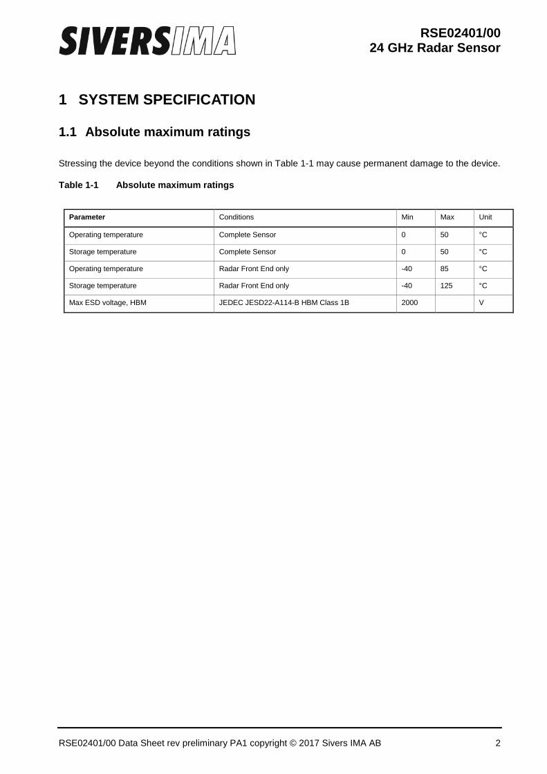
1.1 Absolute maximum ratings Stressing the device beyond the conditions shown in Table 1-1 may cause permanent damage to the device.
Table 1-1 Absolute maximum ratings
Parameter Conditions Min Max Unit
Operating temperature Complete Sensor 0 50 °C
Storage temperature Complete Sensor 0 50 °C
Operating temperature Radar Front End only -40 85 °C
Storage temperature Radar Front End only -40 125 °C
Max ESD voltage, HBM JEDEC JESD22-A114-B HBM Class 1B 2000 V
RSE02401/00 24 GHz Radar Sensor
RSE02401/00 Data Sheet rev preliminary PA1 copyright © 2017 Sivers IMA AB 3
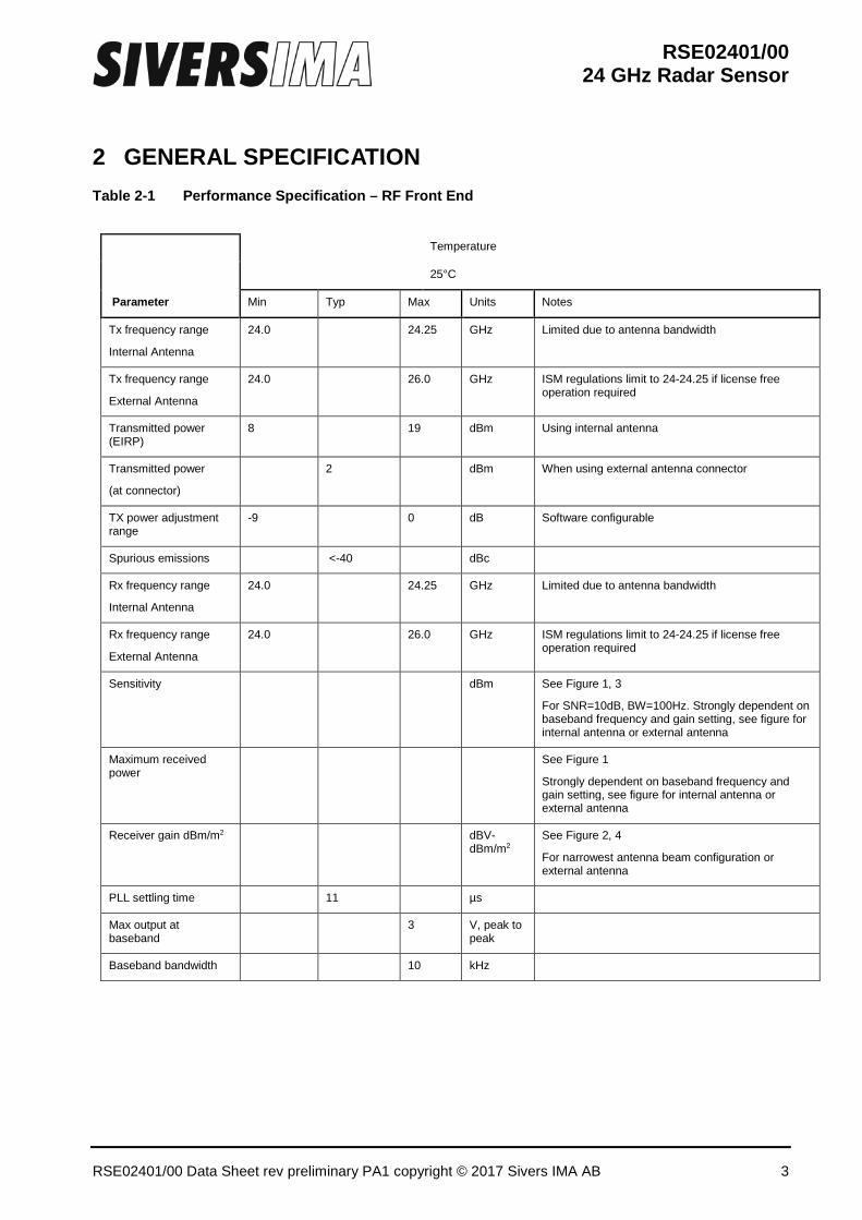
2 GENERAL SPECIFICATION Table 2-1 Performance Specification – RF Front End
Parameter
Temperature
25°C
Min Typ Max Units Notes
Tx frequency range
Internal Antenna
24.0 24.25 GHz Limited due to antenna bandwidth
Tx frequency range
External Antenna
24.0
26.0 GHz ISM regulations limit to 24-24.25 if license free operation required
Transmitted power (EIRP)
8
19 dBm Using internal antenna
Transmitted power
(at connector)
2 dBm When using external antenna connector
TX power adjustment range
-9
0 dB Software configurable
Spurious emissions <-40 dBc
Rx frequency range
Internal Antenna
24.0 24.25 GHz Limited due to antenna bandwidth
Rx frequency range
External Antenna
24.0 26.0 GHz ISM regulations limit to 24-24.25 if license free operation required
Sensitivity
dBm See Figure 1, 3
For SNR=10dB, BW=100Hz. Strongly dependent on baseband frequency and gain setting, see figure for internal antenna or external antenna
Maximum received power
See Figure 1
Strongly dependent on baseband frequency and gain setting, see figure for internal antenna or external antenna
Receiver gain dBm/m2 dBV-dBm/m2
See Figure 2, 4
For narrowest antenna beam configuration or external antenna
PLL settling time 11 µs
Max output at baseband
3 V, peak to peak
Baseband bandwidth 10 kHz
RSE02401/00 24 GHz Radar Sensor
RSE02401/00 Data Sheet rev preliminary PA1 copyright © 2017 Sivers IMA AB 4
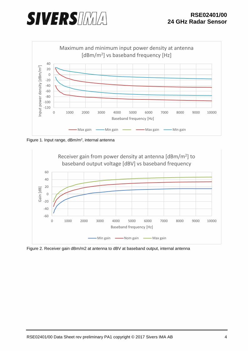
Figure 1. Input range, dBm/m2, internal antenna
Figure 2. Receiver gain dBm/m2 at antenna to dBV at baseband output, internal antenna
-120-100
-80-60-40-20
02040
0 1000 2000 3000 4000 5000 6000 7000 8000 9000 10000
Inpu
t pow
er d
ensit
y [d
Bm/m
2 ]
Baseband frequency [Hz]
Maximum and minimum input power density at antenna [dBm/m2] vs baseband frequency [Hz]
Max gain Min gain Max gain Min gain
-60
-40
-20
0
20
40
60
0 1000 2000 3000 4000 5000 6000 7000 8000 9000 10000
Gain
[dB]
Baseband frequency [Hz]
Receiver gain from power density at antenna [dBm/m2] to baseband output voltage [dBV] vs baseband frequency
Min gain Nom gain Max gain
RSE02401/00 24 GHz Radar Sensor
RSE02401/00 Data Sheet rev preliminary PA1 copyright © 2017 Sivers IMA AB 5
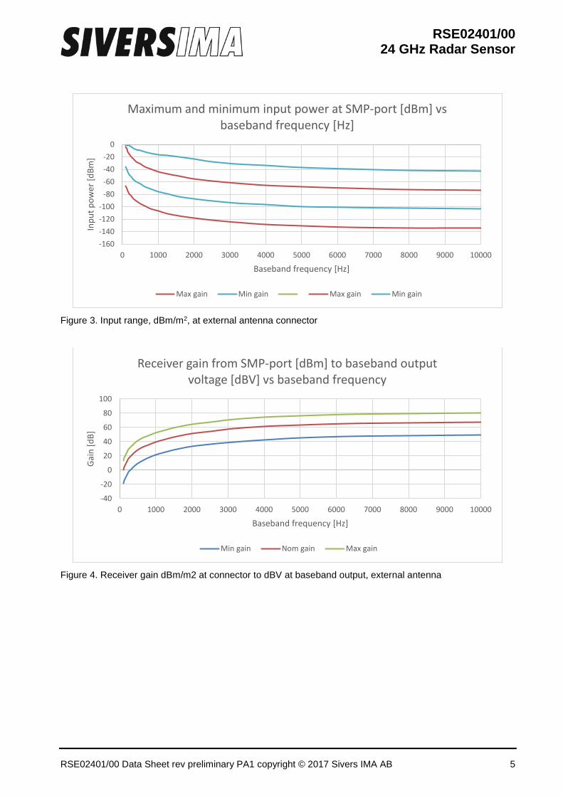
Figure 3. Input range, dBm/m2, at external antenna connector
Figure 4. Receiver gain dBm/m2 at connector to dBV at baseband output, external antenna
-160-140-120-100
-80-60-40-20
0
0 1000 2000 3000 4000 5000 6000 7000 8000 9000 10000
Inpu
t pow
er[d
Bm]
Baseband frequency [Hz]
Maximum and minimum input power at SMP-port [dBm] vs baseband frequency [Hz]
Max gain Min gain Max gain Min gain
-40
-20
0
20
40
60
80
100
0 1000 2000 3000 4000 5000 6000 7000 8000 9000 10000
Gain
[dB]
Baseband frequency [Hz]
Receiver gain from SMP-port [dBm] to baseband output voltage [dBV] vs baseband frequency
Min gain Nom gain Max gain
RSE02401/00 24 GHz Radar Sensor
RSE02401/00 Data Sheet rev preliminary PA1 copyright © 2017 Sivers IMA AB 6
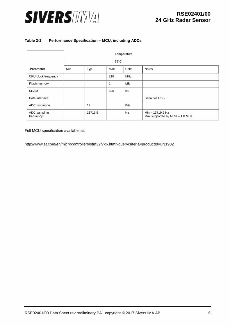
Table 2-2 Performance Specification – MCU, including ADCs
Parameter
Temperature
25°C
Min Typ Max Units Notes
CPU clock frequency
216 MHz
Flash memory
1 MB
SRAM
320 KB
Data interface Serial via USB
ADC resolution
12
Bits
ADC sampling frequency
13719.5
Hz Min = 13719.5 Hz
Max supported by MCU = 1.8 MHz
Full MCU specification available at:
http://www.st.com/en/microcontrollers/stm32f7x6.html?querycriteria=productId=LN1902
RSE02401/00 24 GHz Radar Sensor
RSE02401/00 Data Sheet rev preliminary PA1 copyright © 2017 Sivers IMA AB 7
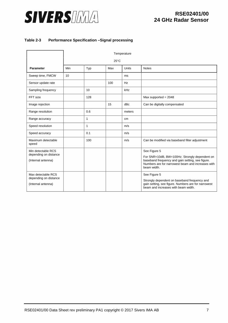
Table 2-3 Performance Specification –Signal processing
Parameter
Temperature
25°C
Min Typ Max Units Notes
Sweep time, FMCW 10
ms
Sensor update rate 100 Hz
Sampling frequency 10 kHz
FFT size
128
Max supported = 2048
Image rejection
15 dBc Can be digitally compensated
Range resolution 0.6 meters
Range accuracy 1 cm
Speed resolution 1 m/s
Speed accuracy 0.1 m/s
Maximum detectable speed
100 m/s Can be modified via baseband filter adjustment
Min detectable RCS depending on distance
(Internal antenna)
See Figure 5
For SNR=10dB, BW=100Hz. Strongly dependent on baseband frequency and gain setting, see figure. Numbers are for narrowest beam and increases with beam width.
Max detectable RCS depending on distance
(Internal antenna)
See Figure 5
Strongly dependent on baseband frequency and gain setting, see figure. Numbers are for narrowest beam and increases with beam width.
RSE02401/00 24 GHz Radar Sensor
RSE02401/00 Data Sheet rev preliminary PA1 copyright © 2017 Sivers IMA AB 8
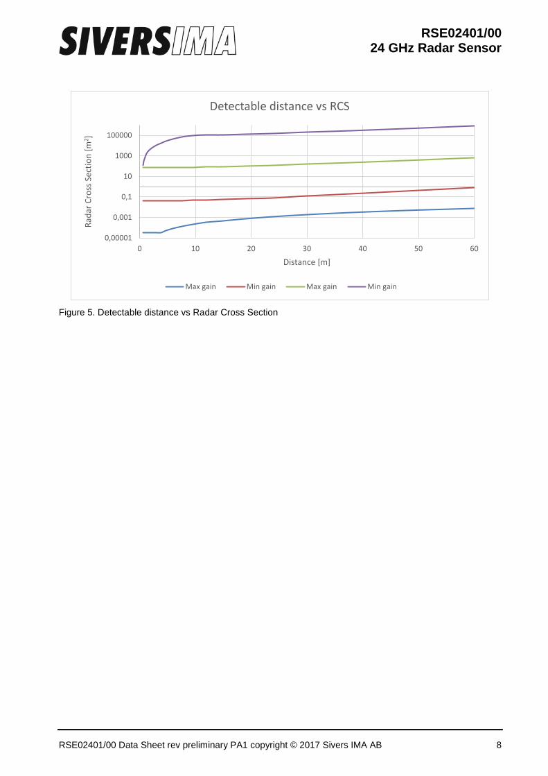
Figure 5. Detectable distance vs Radar Cross Section
0,00001
0,001
0,1
10
1000
100000
0 10 20 30 40 50 60
Rada
r Cro
ss S
ectio
n [m
2 ]
Distance [m]
Detectable distance vs RCS
Max gain Min gain Max gain Min gain
RSE02401/00 24 GHz Radar Sensor
RSE02401/00 Data Sheet rev preliminary PA1 copyright © 2017 Sivers IMA AB 9
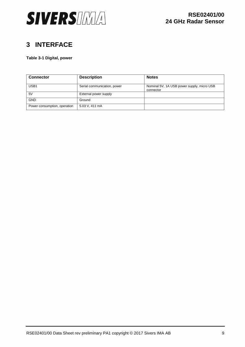
3 INTERFACE Table 3-1 Digital, power
Connector Description Notes
USB1 Serial communication, power Nominal 5V, 1A USB power supply, micro USB connector
5V External power supply
GND Ground
Power consumption, operation 5.03 V, 411 mA
RSE02401/00 24 GHz Radar Sensor
RSE02401/00 Data Sheet rev preliminary PA1 copyright © 2017 Sivers IMA AB 10
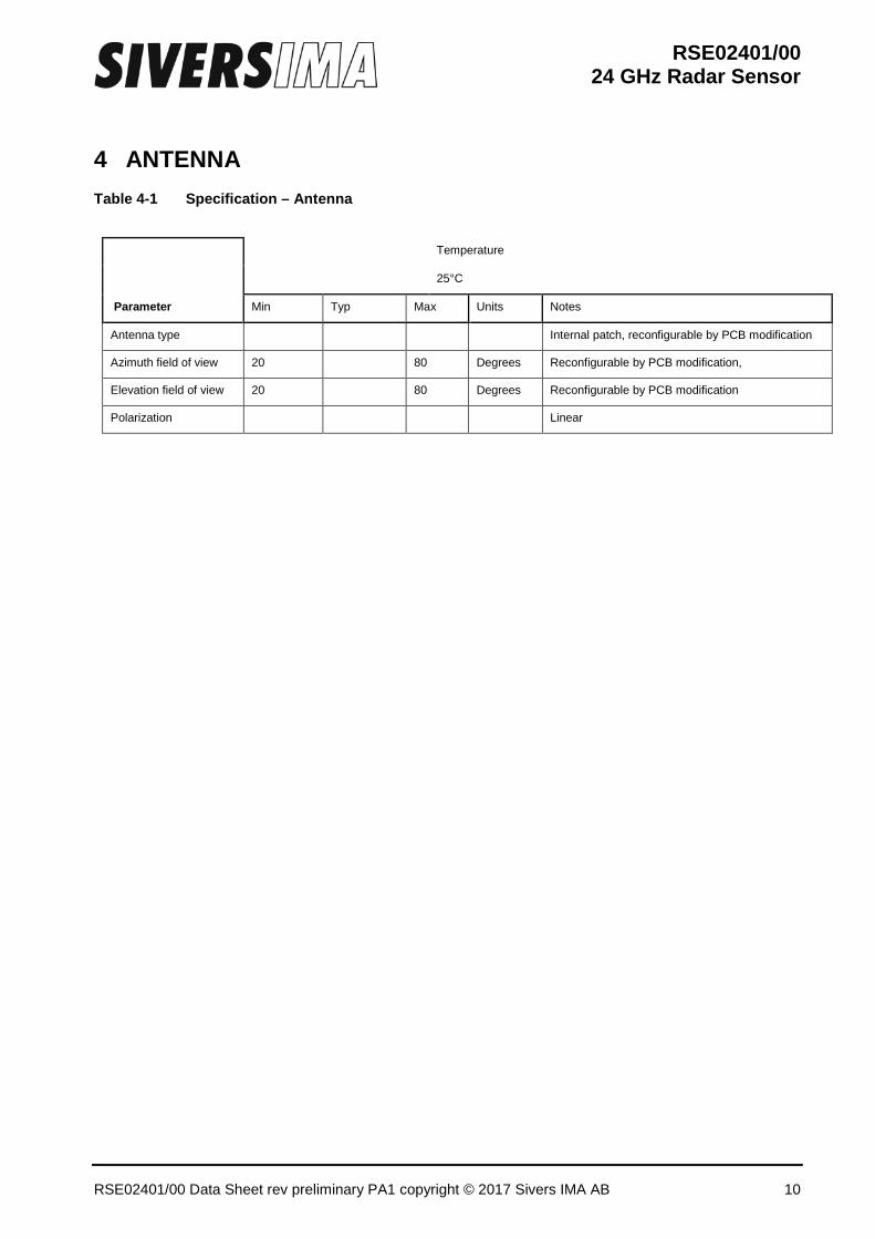
4 ANTENNA Table 4-1 Specification – Antenna
Parameter
Temperature
25°C
Min Typ Max Units Notes
Antenna type
Internal patch, reconfigurable by PCB modification
Azimuth field of view 20
80 Degrees Reconfigurable by PCB modification,
Elevation field of view 20
80 Degrees Reconfigurable by PCB modification
Polarization
Linear
RSE02401/00 24 GHz Radar Sensor
RSE02401/00 Data Sheet rev preliminary PA1 copyright © 2017 Sivers IMA AB 11
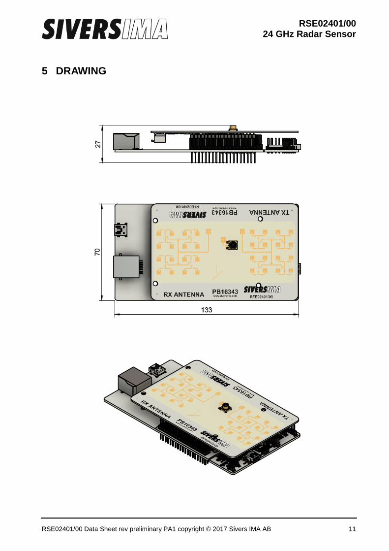
5 DRAWING
RSE02401/00 24 GHz Radar Sensor
RSE02401/00 Data Sheet rev preliminary PA1 copyright © 2017 Sivers IMA AB 12
6 CONTACT For further technical and/or commercial questions, please contact: Sivers IMA AB Torshamnsgatan 9 SE-164 29 Kista [email protected] www.siversima.com