r&s fs-k9 measurements with power sensors … · r&s fs-k9 installation and enabling...
TRANSCRIPT
R&S®FS-K9 Measurements with Power Sensors Software Manual
Softw
are
Man
ual
Test and M
easure
me
nt
1157.3029.42 – 05
PA
D-T
-M: 3574.3
259.0
2/0
1.0
0/C
I/1/E
N

© 2014 Rohde & Schwarz GmbH & Co. KG
Muehldorfstr. 15, 81671 Munich, Germany
Phone: +49 89 41 29 - 0
Fax: +49 89 41 29 12 164
E-mail: [email protected]
Internet: http://www.rohde-schwarz.com
Subject to change – Data without tolerance limits is not binding.
R&S® is a registered trademark of Rohde & Schwarz GmbH & Co. KG.
Trade names are trademarks of the owners.
The following abbreviations are used throughout this manual:
R&S®FS-K9 is abbreviated as R&S FS-K9
R&S FS-K9 Contents
Software Manual 1157.3029.42 - 05 3
Contents
1 Installation and Enabling ................................................................... 5
1.1 Installation .................................................................................................................... 5
1.2 Enabling ........................................................................................................................ 5
2 Getting Started .................................................................................... 6
3 Test Setup for Measurements with Power Sensors ......................... 7
3.1 Standard Test Setup .................................................................................................... 7
4 Configuration of Power Measurement .............................................. 8
4.1 Menu PWR METER - NEXT ........................................................................................13
5 Remote Control Commands ............................................................ 17
5.1 Common Commands .................................................................................................17
5.2 CALCulate:PMETer Subsystem ................................................................................17
5.3 CALibration Subsystem ............................................................................................18
5.4 DISPlay Subsystem ...................................................................................................19
5.5 FETCh:PMETer Subsystem ......................................................................................20
5.6 INITiate Subsystem ....................................................................................................20
5.7 READ:PMETer Subsystem ........................................................................................21
5.8 SENSe:CORRection – Subsystem ...........................................................................22
5.9 SENSe:PMETer Subsystem ......................................................................................23
5.10 SYSTem Subsystem ..................................................................................................26
5.11 UNIT Subsystem ........................................................................................................28
5.12 Table of Softkeys with Assignment of IEC/IEEE Bus Commands ........................28
5.12.1 PWR METER Hotkey ...................................................................................................28
5.12.2 AMPL Key ....................................................................................................................30
5.12.3 SWEEP Key .................................................................................................................30
6 Index .................................................................................................. 31

R&S FS-K9 Installation and Enabling
Software Manual 1157.3029.42 - 05 5
1 Installation and Enabling
1.1 Installation
Application Firmware R&S FS-K9 is part of the basic firmware of the base unit. The
application is available starting with basic firmware version 3.2x.
If the basic firmware has to be updated, start the update with the floppy disks
containing the basic firmware by SETUP → NEXT → FIRMWARE UPDATE.
The instrument must be switched off before connecting the power sensor.
The drivers required for controlling the power sensor are installed along with the basic
firmware for the analyzer, i.e. the software supplied with the power meter does not
have to be installed.
The R&S NRP-Zx power sensor is connected to the instrument using the R&S NRP
USB adapter. For details, refer the operating manual for the R&S NRP-Zx power
sensor.
1.2 Enabling
Application Firmware R&S FS-K9 is enabled in the SETUP → GENERAL SETUP
menu by entering a keyword. The keyword is supplied together with the application
firmware. If the application firmware is installed at the factory, it will already be
enabled.
GENERAL SETUP menu:
The OPTIONS softkey opens a submenu in which you can enter the keywords for the
application firmware. The existing applications are displayed in a table that opens
when you enter the submenu.
INSTALL OPTION
The INSTALL OPTION softkey enables entry of the keyword for application firmware.
If the keyword is valid, the message OPTION KEY OK is displayed and the application
firmware is entered in the FIRMWARE OPTIONS table.
If an invalid keyword is entered, OPTION KEY INVALID is displayed.

R&S FS-K9 Getting Started
Software Manual 1157.3029.42 - 05 6
2 Getting Started
Before you can start measurements, you must adjust the instrument settings to the
properties of the device under test. The following procedure is recommended:
1. Set the spectrum analyzer to its default state.
─ Press the PRESET button.
The device is now in its default state.
2. Activate measurements with the power sensor.
─ Press the PWR METER hotkey.
Measurements with the power sensor will be activated and the menu with the
settings for the power sensor will be opened.
3. Set the frequency
─ In the default setting, the frequency of the power sensor is coupled with the
center frequency of the analyzer, i.e. when the center frequency of the
analyzer is set (FREQ button), the power sensor is automatically set to the
frequency to be measured.
4. Set the measurement time.
─ Press the MEAS TIME softkey.
The list of available measurement times is opened.
─ Using the cursor keys, select the desired measurement time and confirm with
ENTER.
5. Set the unit
─ Press the UNIT / SCALE softkey.
The list of available units will be opened.
─ Using the cursor keys, select the desired unit and confirm with ENTER.
Additional setting options are described in the following reference section of the
manual.

R&S FS-K9 Test Setup for Measurements with Power Sensors
Software Manual 1157.3029.42 - 05 7
3 Test Setup for Measurements with Power
Sensors
Not complying with these precautions may cause damage to the instrument.
Before the instrument is put into operation, make sure the following are done:
The instrument cover is on and screwed into place.
The ventilation openings are unobstructed.
No signal voltage levels exceed permitted limits.
The instrument outputs are not overloaded or improperly connected.
This chapter describes the basic settings for the analyzer for measurements with a
power sensor. Before measurements can be started, the analyzer must be correctly
configured and powered as described in Chapter 1 of the operating manual for the
base unit. Furthermore, Application Firmware R&S FS-K9 must be enabled. Chapter 1
of this manual describes how to install and enable the application firmware.
3.1 Standard Test Setup
0
1 2 3
4 5 6
7 8 9
. -
ESC
1129.9003.03
FCTN
ENTERCANCEL
M EAS TRIG
FREQ
M KR
AM PTSPAN
M KRM KR
BW SWEEP
TRACE
LINES
DISP
FILE
G Hz
MHz
k Hz
Hz
-dBm
dBm
dB
dB. .
CAL
SETUP
PRESET
HCOPY
SPECTRUM AN ALYZ ER 20 Hz . . . 3 .6G Hz..FSU
BACK
s
V
msmV
µs
µV
ns
nV
PREV NEXT
MADE IN G ER MANY
.
POWER SENSOR
GEN OUTPUT 50
AF O UTPU T
RF IN PU T 50EXT M IXER
LO OU T/ IF I N I F I N
M AX +30 dBm / 0V DC
KEYBOARD
M AX 0V DC
PROBE POWER
I IN
Q IN
NOISE SOURCE
Signal
Source
USB
Power Sensor
NRP-Z11 or
NRP-Z21
USB Adapter
NRP-Z4
Figure 1 Test setup

R&S FS-K9 Configuration of Power Measurement
Software Manual 1157.3029.42 - 05 8
4 Configuration of Power Measurement
Application Firmware R&S FS-K9 (measurements with power sensor) is activated with
the PWR METER hotkey.
SPECTRUM SCREEN BPWR METER
Figure 2 Hotkey bar with Application Firmware R&S FS-K9 enabled
Figure 3 Result display of Application Firmware R&S FS-K9
If the hotkey bar is being used by an application, Application Firmware R&S FS-K9 can
also be activated by pressing SETUP NEXT PWR METER.
R&S FS-K9 Configuration of Power Measurement
Software Manual 1157.3029.42 - 05 9
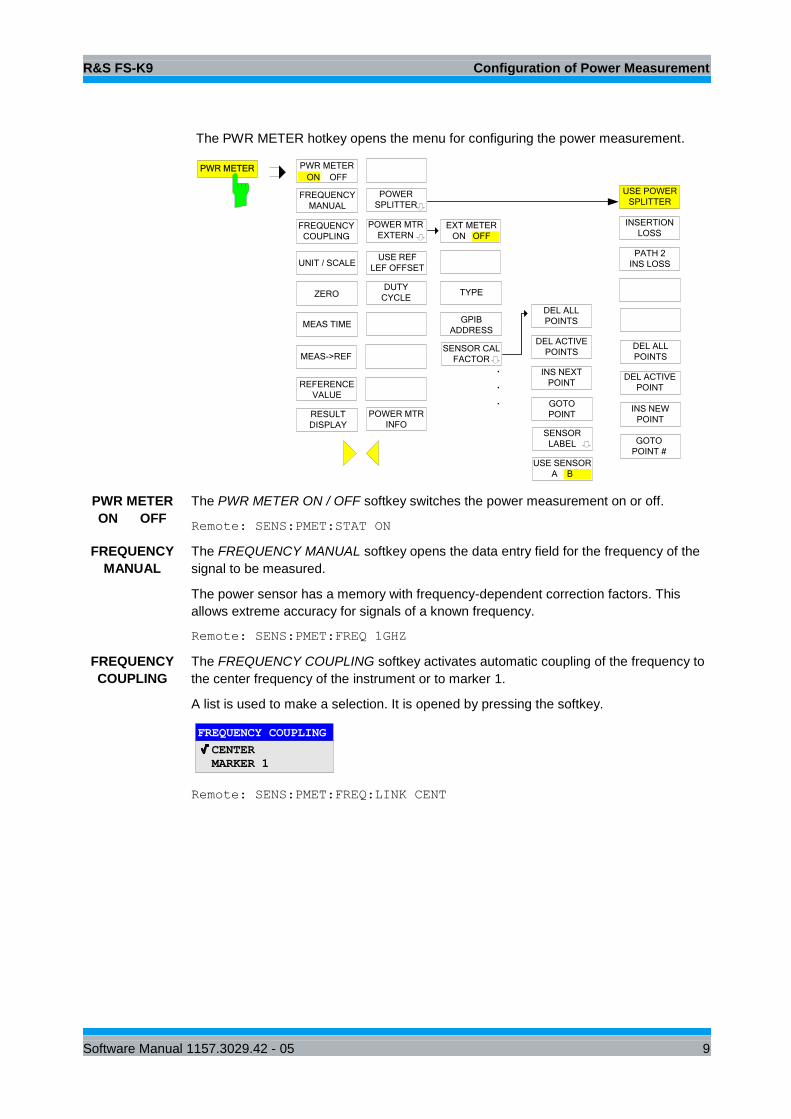
The PWR METER hotkey opens the menu for configuring the power measurement.
PWR METER
ON OFF
UNIT / SCALE
ZERO
MEAS->REF
FREQUENCY
COUPLING
PWR METER
REFERENCE
VALUE
FREQUENCY
MANUAL
RESULT
DISPLAY
MEAS TIME
EXT METER
ON OFF
GPIB
ADDRESS
POWER MTR
EXTERN
TYPE
SENSOR CAL
FACTOR.
.
.
DEL ALL
POINTS
GOTO
POINT
INS NEXT
POINT
SENSOR
LABEL
DEL ACTIVE
POINTS
USE SENSOR
A B
USE POWER
SPLITTER
INSERTION
LOSS
DEL ALL
POINTS
INS NEW
POINT
GOTO
POINT #
POWER
SPLITTER
PATH 2
INS LOSS
DEL ACTIVE
POINT
USE REF
LEF OFFSET
DUTY
CYCLE
POWER MTR
INFO
PWR METER
ON OFF
The PWR METER ON / OFF softkey switches the power measurement on or off.
Remote: SENS:PMET:STAT ON
FREQUENCY
MANUAL
The FREQUENCY MANUAL softkey opens the data entry field for the frequency of the
signal to be measured.
The power sensor has a memory with frequency-dependent correction factors. This
allows extreme accuracy for signals of a known frequency.
Remote: SENS:PMET:FREQ 1GHZ
FREQUENCY
COUPLING
The FREQUENCY COUPLING softkey activates automatic coupling of the frequency to
the center frequency of the instrument or to marker 1.
A list is used to make a selection. It is opened by pressing the softkey.
FREQUENCY COUPLING
CENTER
MARKER 1
Remote: SENS:PMET:FREQ:LINK CENT
R&S FS-K9 Configuration of Power Measurement
Software Manual 1157.3029.42 - 05 10
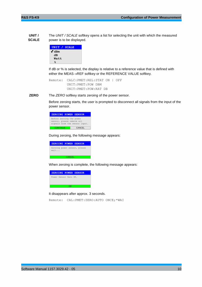
UNIT /
SCALE
The UNIT / SCALE softkey opens a list for selecting the unit with which the measured
power is to be displayed.
UNIT / SCALE
dB
dB
Watt
m
%
If dB or % is selected, the display is relative to a reference value that is defined with
either the MEASREF softkey or the REFERENCE VALUE softkey.
Remote: CALC:PMET:REL:STAT ON | OFF
UNIT:PMET:POW DBM
UNIT:PMET:POW:RAT DB
ZERO The ZERO softkey starts zeroing of the power sensor.
Before zeroing starts, the user is prompted to disconnect all signals from the input of the
power sensor.
ZEROING POWER SENSOR
Before zeroing the power
sensor, please remove all
signals from the sensor input.
CONTINUE CANCEL
During zeroing, the following message appears:
ZEROING POWER SENSOR
Zeroing power sensor, please
wait...
CANCEL
When zeroing is complete, the following message appears:
ZEROING POWER SENSOR
Power Sensor Zero OK.
OK
It disappears after approx. 3 seconds.
Remote: CAL:PMET:ZERO:AUTO ONCE;*WAI
R&S FS-K9 Configuration of Power Measurement
Software Manual 1157.3029.42 - 05 11
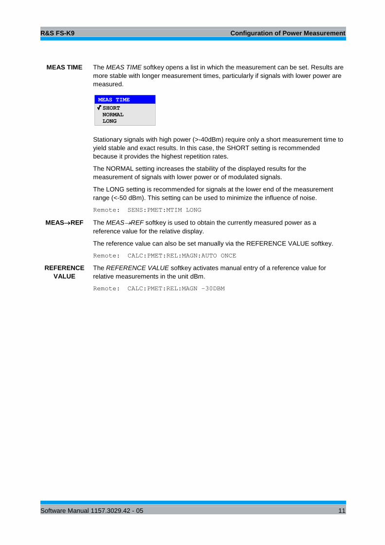
MEAS TIME The MEAS TIME softkey opens a list in which the measurement can be set. Results are
more stable with longer measurement times, particularly if signals with lower power are
measured.
MEAS TIME
SHORT
NORMAL
LONG
Stationary signals with high power (>-40dBm) require only a short measurement time to
yield stable and exact results. In this case, the SHORT setting is recommended
because it provides the highest repetition rates.
The NORMAL setting increases the stability of the displayed results for the
measurement of signals with lower power or of modulated signals.
The LONG setting is recommended for signals at the lower end of the measurement
range (<-50 dBm). This setting can be used to minimize the influence of noise.
Remote: SENS:PMET:MTIM LONG
MEASREF The MEASREF softkey is used to obtain the currently measured power as a
reference value for the relative display.
The reference value can also be set manually via the REFERENCE VALUE softkey.
Remote: CALC:PMET:REL:MAGN:AUTO ONCE
REFERENCE
VALUE
The REFERENCE VALUE softkey activates manual entry of a reference value for
relative measurements in the unit dBm.
Remote: CALC:PMET:REL:MAGN –30DBM

R&S FS-K9 Configuration of Power Measurement
Software Manual 1157.3029.42 - 05 12
RESULT
DISPLAY
The RESULT DISPLAY softkey switches the result display of the power measurement
on or off. If the display is switched off, the measured power appears in the Marker Info
field.
Note:
The softkey is available only in the spectrum analysis mode as long as the lower
half of the screen is not already being used for another result display (e.g. ACP
measurement).
Figure 4 Result display with RESULT DISPLAY ON
Figure 5 Result display with RESULT DISPLAY OFF
Remote: DISP:WIND:PMET:STAT OFF
R&S FS-K9 Configuration of Power Measurement
Software Manual 1157.3029.42 - 05 13
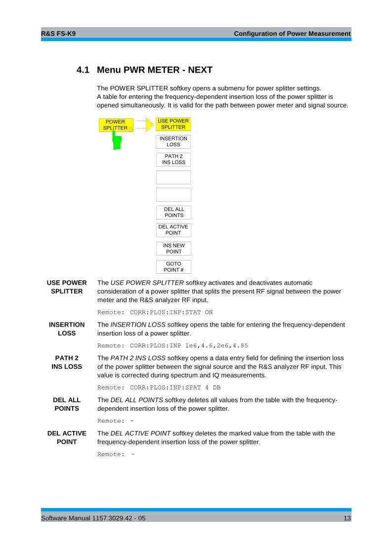
4.1 Menu PWR METER - NEXT
The POWER SPLITTER softkey opens a submenu for power splitter settings.
A table for entering the frequency-dependent insertion loss of the power splitter is
opened simultaneously. It is valid for the path between power meter and signal source.
USE POWER
SPLITTER
INSERTION
LOSS
DEL ALL
POINTS
INS NEW
POINT
GOTO
POINT #
POWER
SPLITTER
PATH 2
INS LOSS
DEL ACTIVE
POINT
USE POWER
SPLITTER
The USE POWER SPLITTER softkey activates and deactivates automatic
consideration of a power splitter that splits the present RF signal between the power
meter and the R&S analyzer RF input.
Remote: CORR:PLOS:INP:STAT ON
INSERTION
LOSS
The INSERTION LOSS softkey opens the table for entering the frequency-dependent
insertion loss of a power splitter.
Remote: CORR:PLOS:INP 1e6,4.6,2e6,4.85
PATH 2
INS LOSS
The PATH 2 INS LOSS softkey opens a data entry field for defining the insertion loss
of the power splitter between the signal source and the R&S analyzer RF input. This
value is corrected during spectrum and IQ measurements.
Remote: CORR:PLOS:INP:SPAT 4 DB
DEL ALL
POINTS
The DEL ALL POINTS softkey deletes all values from the table with the frequency-
dependent insertion loss of the power splitter.
Remote: -
DEL ACTIVE
POINT
The DEL ACTIVE POINT softkey deletes the marked value from the table with the
frequency-dependent insertion loss of the power splitter.
Remote: -
R&S FS-K9 Configuration of Power Measurement
Software Manual 1157.3029.42 - 05 14
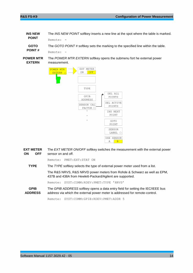
INS NEW
POINT
The INS NEW POINT softkey inserts a new line at the spot where the table is marked.
Remote: -
GOTO
POINT #
The GOTO POINT # softkey sets the marking to the specified line within the table.
Remote: -
POWER MTR
EXTERN
The POWER MTR EXTERN softkey opens the submenu fort he external power
measurement.
EXT METER
ON OFF
GPIB
ADDRESS
POWER MTR
EXTERN
TYPE
SENSOR CAL
FACTOR.
.
.
DEL ALL
POINTS
GOTO
POINT
INS NEXT
POINT
SENSOR
LABEL
DEL ACTIVE
POINTS
USE SENSOR
A B
EXT METER
ON OFF
The EXT METER ON/OFF softkey switches the measurement with the external power
sensor on and off.
Remote: PMET:EXT:STAT ON
TYPE The TYPE softkey selects the type of external power meter used from a list.
The R&S NRVS, R&S NRVD power meters from Rohde & Schwarz as well as EPM,
437B and 438A from Hewlett-Packard/Agilent are supported.
Remote: SYST:COMM:RDEV:PMET:TYPE ’NRVS’
GPIB
ADDRESS
The GPIB ADDRESS softkey opens a data entry field for setting the IEC/IEEE bus
address via which the external power meter is addressed for remote-control.
Remote: SYST:COMM:GPIB:RDEV:PMET:ADDR 5
R&S FS-K9 Configuration of Power Measurement
Software Manual 1157.3029.42 - 05 15
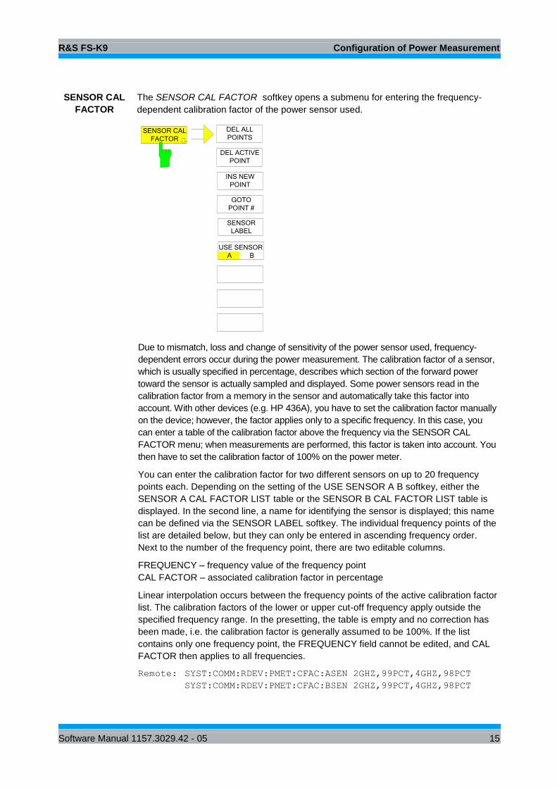
SENSOR CAL
FACTOR
The SENSOR CAL FACTOR softkey opens a submenu for entering the frequency-
dependent calibration factor of the power sensor used.
DEL ALL
POINTS
INS NEW
POINT
GOTO
POINT #
SENSOR CAL
FACTOR
DEL ACTIVE
POINT
SENSOR
LABEL
USE SENSOR
A B
Due to mismatch, loss and change of sensitivity of the power sensor used, frequency-
dependent errors occur during the power measurement. The calibration factor of a sensor,
which is usually specified in percentage, describes which section of the forward power
toward the sensor is actually sampled and displayed. Some power sensors read in the
calibration factor from a memory in the sensor and automatically take this factor into
account. With other devices (e.g. HP 436A), you have to set the calibration factor manually
on the device; however, the factor applies only to a specific frequency. In this case, you
can enter a table of the calibration factor above the frequency via the SENSOR CAL
FACTOR menu; when measurements are performed, this factor is taken into account. You
then have to set the calibration factor of 100% on the power meter.
You can enter the calibration factor for two different sensors on up to 20 frequency
points each. Depending on the setting of the USE SENSOR A B softkey, either the
SENSOR A CAL FACTOR LIST table or the SENSOR B CAL FACTOR LIST table is
displayed. In the second line, a name for identifying the sensor is displayed; this name
can be defined via the SENSOR LABEL softkey. The individual frequency points of the
list are detailed below, but they can only be entered in ascending frequency order.
Next to the number of the frequency point, there are two editable columns.
FREQUENCY – frequency value of the frequency point
CAL FACTOR – associated calibration factor in percentage
Linear interpolation occurs between the frequency points of the active calibration factor
list. The calibration factors of the lower or upper cut-off frequency apply outside the
specified frequency range. In the presetting, the table is empty and no correction has
been made, i.e. the calibration factor is generally assumed to be 100%. If the list
contains only one frequency point, the FREQUENCY field cannot be edited, and CAL
FACTOR then applies to all frequencies.
Remote: SYST:COMM:RDEV:PMET:CFAC:ASEN 2GHZ,99PCT,4GHZ,98PCT
SYST:COMM:RDEV:PMET:CFAC:BSEN 2GHZ,99PCT,4GHZ,98PCT
R&S FS-K9 Configuration of Power Measurement
Software Manual 1157.3029.42 - 05 16
DEL ALL
POINTS
The DEL ALL POINTS softkey deletes all values from the table with the frequency-
dependent insertion loss of the power splitter.
Remote: -
DEL ACTIVE
POINT
The DEL ACTIVE POINT softkey deletes the marked value from the table with the
frequency-dependent insertion loss of the power splitter.
Remote: -
INS NEW
POINT
The INS NEW POINT softkey inserts a new line where the table is marked.
Remote: -
GOTO
POINT #
The GOTO POINT # softkey sets the marking to the specified line within the table.
Remote: -
SENSOR
LABEL
The SENSOR LABEL softkey sets the marking within the table to the LABEL line so
that an alphanumeric label can be entered.
Remote: SYST:COMM:RDEV:PMET:CFAC:ASEN:LAB ’SENSOR1’
SYST:COMM:RDEV:PMET:CFAC:BSEN:LAB ’SENSOR2’
USE SENSOR
A B
The USE SENSOR A/B softkey switches between the calibration factors of the sensors
A and B.
Switchover refers both to the table displayed and to the data set used during power
calibration.
Remote: SYST:COMM:RDEV:PMET:CFAC:SEL ASEN | BSEN
USE REF
LEV OFFSET
The USE REF LEV OFFSET softkey controls whether the analyzer reference level
offset is taken into account of the measured power (state ON) or not (state OFF).
Remote: SENS1:PMET:ROFF:STAT ON | OFF
DUTY
CYCLE
The DUTY CYCLE softkey opens a dialog to set the duty cycle to a percent value for
the correction of pulsemodulated signals. With the correction activated, the sensor
calculates the signal pulse power from this value and the mean power. The softkey is
highlighted if the correction is switched on.
Press the softkey again to switch the Duty Cycle correction off.
Valid entries are from 0.001 % to 99.999%; the stepsize is 0.1 %; the maximum
resolution for numerial entries is 0.001 dB. The default setting is 99.999%
Remote: SENS1:PMET:DCYC:STAT ON | OFF
SENS1:PMET:DCYC:VAL 0.001 … 99.999 PCT
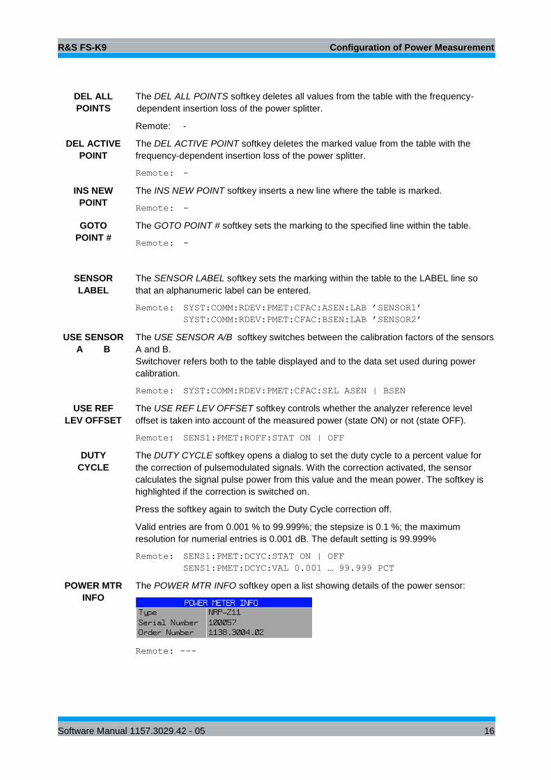
POWER MTR
INFO
The POWER MTR INFO softkey open a list showing details of the power sensor:
Remote: ---
R&S FS-K9 Remote Control Commands
Software Manual 1157.3029.42 - 05 17
5 Remote Control Commands
This chapter describes the remote control commands for the application firmware. An
alphabetic list following the text of the manual provides a quick overview of the
commands.
The commands that also apply to the base unit in the SPECTRUM mode and the
system settings are described in the operating manual for the analyzer.
5.1 Common Commands
OPT?
OPTION IDENTIFICATION QUERY polls the options contained in the device and
returns a list of installed options. The options are separated by commas. The
identifier for option R&S FS-K9 is contained in the response string at position 34:
Example:
0,0,0,0,0,0,0,0,0,0,0,0,0,0,0,0,0,0,0,0,0,0,0,0,0,0,0,0,0,0,0,0,0,K9,0,0,0,0,0,0,0,0,0,0,0,
0,0,0,0,0
5.2 CALCulate:PMETer Subsystem
This subsystem controls the settings of the instrument for measurements with a power
sensor. The measurement window is selected via CALCulate1 (SCREEN A) and
CALCulate2 (SCREEN B).
CALCulate<1|2>:PMETer:RELative[:MAGNitude] -200 to 200
This command sets the reference value for relative measurements
Example
CALC:PMET:REL –30
'sets the reference value for relative measurements to –30 dBm
Characteristics
* RST value: 0
SCPI: device-specific
CALCulate<1|2>:PMETer:RELative[:MAGNitude]:AUTO ONCE
This command accepts the current result as a reference value for relative
measurements
Example
CALC:PMET:REL:AUTO ONCE
'accepts the current result as a reference value for
R&S FS-K9 Remote Control Commands
Software Manual 1157.3029.42 - 05 18
'relative measurements
Characteristics
* RST value: -
SCPI: device-specific
CALCulate<1|2>:PMETer:RELative:STATe ON | OFF
This command switches between relative and absolute display of the result.
Example
CALC:PMET:REL:STAT ON
'activates relative display of the result
Characteristics
* RST value: OFF
SCPI: device-specific
5.3 CALibration Subsystem
The commands of the CALibration subsystem determine the data for system error
correction in the instrument.
CALibration:PMETer:ZERO:AUTO ONCE
This command zeroes the power sensor
Example
CAL:PMET:ZERO:AUTO ONCE;*WAI
'zeroes the power sensor and waits until zeroing is
'completed before executing additional commands
Characteristics
* RST value: -
SCPI: device-specific
R&S FS-K9 Remote Control Commands
Software Manual 1157.3029.42 - 05 19
5.4 DISPlay Subsystem
The DISPLay subsystem controls the selection and presentation of text and graphics
information as well as measurement data on the screen.
The measurement window is selected via WINDow1 (SCREEN A) or WINDow2
(SCREEN B).
DISPlay[:WINDow<1|2>]:TRACe<1 to 3>:Y[:SCALe]:RLEVel:OFFSet –200 dB to
200 dB
This command defines the reference level offset in the selected measurement
window. Depending on the coupling of the measurement windows, this command
is valid for both screens (INST:COUP ALL) or only for the selected measurement
window (INST:COUP NONE)
The numeric suffix under TRACe <1...3> is irrelevant.
Example
DISP:WIND1:TRAC:Y:RLEV:OFFS -10dB
Characteristics
* RST value: 0 dB
SCPI: compliant
DISPlay[:WINDow<1|2>]:PMETer:STATe ON | OFF
This command switches bargraph display on or off for measurements with a
power sensor. If bargraph display is switched off, the measurement value
appears in the Marker Info field.
Example
DISP:PMET:STAT OFF
'switches bargraph display off
Characteristics
* RST value: ON
SCPI: device-specific
R&S FS-K9 Remote Control Commands
Software Manual 1157.3029.42 - 05 20
5.5 FETCh:PMETer Subsystem
This subsystem contains the commands for outputting the results of the measurements
with a power sensor without starting the measurement itself.
FETCh<1|2>:PMETer?
This command outputs the result of the power sensor.
If no measurement has been carried out yet, a query error is triggered. This
command is strictly a query and thus does not have a *RST value.
Example
FETC:PMET?
'outputs the result of the power sensor
Characteristics
* RST value: -
SCPI: device-specific
5.6 INITiate Subsystem
The INITiate subsystem is used to control the measurement sequence in the
selected measurement window. The measurement window is selected using
INITiate1 (SCREEN A) and INITiate2 (SCREEN B)
INITiate<1|2>:CONTinuous ON | OFF
This command determines whether the device performs measurements
continuously ("Continuous") or only individual measurements ("Single“).
In the spectrum analysis mode, this setting refers to the sweep operation
(switchover between Continuous and Single Sweep).
Example
INIT2:CONT OFF
'switches operation in screen B to Single Sweep
INIT2:CONT ON
'switches operation to Continuous Sweep
Characteristics
* RST value: ON
SCPI: compliant
R&S FS-K9 Remote Control Commands
Software Manual 1157.3029.42 - 05 21
INITiate<1|2>[:IMMediate]
This command starts a new measurement sequence in the specified
measurement window.
This command starts a new measurement sequence (sweep) in the specified
measurement window. A sweep count > 0 or average count > 0 means the
number of specified measurements will be restarted. In the case of the trace
functions MAXHold, MINHold and AVERage, the previous results are reset when
the measurement is restarted.
In the Single Sweep mode, the commands *OPC, *OPC? or *WAI can be used to
perform synchronization with the end of the specified number of measurements. In
the Continuous Sweep mode, synchronization with the end of the sweep is not
possible because the entire measurement "never" actually ends.
Example
INIT:CONT OFF
'switches to Single Sweep mode
DISP:WIND:TRAC:MODE AVER
'activates Trace Averaging
SWE:COUN 20
'sets the sweep counter to 20 sweeps
INIT;*WAI
'starts the measurement by waiting for the end of 20
'measurements
Characteristics
* RST value: -
SCPI: compliant
5.7 READ:PMETer Subsystem
This subsystem contains the commands for starting measurements with a power
sensor and outputting the results.
READ<1|2>:PMETer?
This command triggers a measurement with the power sensor and then outputs
the result.
This command is strictly a query and thus does not have a *RST value.
Example
READ:PMET
'starts a measurement and output the result
Characteristics
* RST value: -
SCPI: device-specific

R&S FS-K9 Remote Control Commands
Software Manual 1157.3029.42 - 05 22
5.8 SENSe:CORRection – Subsystem
This subsystem controls the settings of the power splitter.
[SENSe<1|2>:]CORRection:PLOSs:INPut <numeric_value>,<numeric_value> …
This command enters the frequency-dependent insertion loss of a power splitter.
Example
CORR:PLOS:INP 1e6,4.6,2e6,4.85
Characteristics
* RST value: -
SCPI: device-specific
[SENSe<1|2>:]CORRection:PLOSs:INPut:STATe ON | OFF
This command activates and deactivates automatic consideration of a power
splitter that splits the present RF signal between the power meter and the R&S
analyzer RF input.
Example
CORR:PLOS:INP:STAT ON
Characteristics
* RST value: -
SCPI: device-specific
[SENSe<1|2>:]CORRection:PLOSs:INPut:SPATh <numeric_value>
This command defins the insertion loss of the power splitter between the signal
source and the R&S analyzer RF input. This value is corrected during spectrum
and IQ measurements.
Example
CORR:PLOS:INP:SPAT 4 DB
Characteristics
* RST value: -
SCPI: device-specific
R&S FS-K9 Remote Control Commands
Software Manual 1157.3029.42 - 05 23
5.9 SENSe:PMETer Subsystem
This subsystem controls the settings of the instrument for measurements with a power
sensor. The measurement window is selected via SENSe1 (SCREEN A) and SENSe2
(SCREEN B).
[SENSe<1|2>:]PMETer[:STATe] ON | OFF
This command switches measurements with a power sensor on or off.
Example
PMET ON
'switches measurements with a power sensor on
Characteristics
* RST value: OFF
SCPI: device-specific
SENSe<1|2>:]PMETer:DCYCle:STATe ON | OFF
This command controls the calculation of the signal pulse power from the mean
power. The duty cycle has to be set by SENS:PMET:DCYC:VAL according to
characteristics of the input signal if the calculation is switched on.
Example
SENS:PMET:STAT ON
'activate power meter
SENS:PMET:DCYC:STAT ON
'switch the correction on
SENS:PMET:DCYC:VAL 50.0
'set the duty cycle to 50 %
Characteristics
* RST value: OFF
SCPI: device-specific
[SENSe<1|2>:]PMETer:DCYCle:VALue 0.001 … 99.999
This command sets the duty cycle to a percent value for the correction of
pulsemodulated signals. With the correction activated (SENS:PMET:DCYC:STAT
ON), the sensor calculates the signal pulse power from this value and the mean
power. Valid entries are from 0.001% to 99.999%; the stepsize is 0.1%; the
maximum resolution for numerial entries is 0.001%. The default setting is
99.999%
Example
SENS:PMET:STAT ON
'activate power meter
R&S FS-K9 Remote Control Commands
Software Manual 1157.3029.42 - 05 24
SENS:PMET:DCYC:STAT ON
'switch the correction on
SENS:PMET:DCYC:VAL 50.0
'set the duty cycle to 50 %
Characteristics
* RST value: 99.999 PCT
SCPI: device-specific
[SENSe<1|2>:]PMETer:EXTern[:STATe] ON | OFF
This command switches measurements with an external power sensor on or off.
Example
PMET:EXT ON
'switches measurements with an external power sensor on
Characteristics
* RST value: OFF
SCPI: device-specific
[SENSe<1|2>:]PMETer:FREQuency fmin to fmax
This command sets the frequency of the power sensor..
The limit values fmin and fmax are set by the power sensor that is connected.
Example
PMET:FREQ 1GHZ
'sets the frequency of the power sensor to 1 GHz
Characteristics
* RST value: 50 MHz
SCPI: device-specific
[SENSe<1|2>:]PMETer:FREQuency:LINK CENTer | MARKer1 | OFF
This command sets the coupling for the frequency of the power sensor.
Parameters
CENTer couples the frequency to the center frequency of the analyzer
MARKer1 couples the frequency to the position of marker 1
OFF deactivates the coupling of the frequency
Example
PMET:FREQ:LINK CENT
'couples the frequency to the center frequency of the
'analyzer
R&S FS-K9 Remote Control Commands
Software Manual 1157.3029.42 - 05 25
Characteristics
* RST value: CENT
SCPI: device-specific
[SENSe<1|2>:]PMETer:MTIMe SHORt | NORMal | LONG
This command determines the measurement time of the power sensor.
Example
PMET:MTIM SHOR
'selects the short time for the measurement of ‘stationary
signals with high power
Characteristics
* RST value: NORM
SCPI: device-specific
This command defines whether the reference level offset set for the analyzer is taken
into account for the measured power or not.
[SENSe<1|2>:]PMETer:ROFFset:STATe ON | OFF
This command controls whether the analyzer reference level offset is taken into
account of the measured power (state ON) or not (state OFF).
Example
SENS:PMET ON
'switches measurements with a power sensor on
SENS:PMET:ROFF:STAT ON
'switches the reference level offset
Characteristics
* RST value: ON
SCPI: device-specific
R&S FS-K9 Remote Control Commands
Software Manual 1157.3029.42 - 05 26
5.10 SYSTem Subsystem
This subsystem contains the command for setting the external power sensors.
SYSTem:COMMunicate:GPIB:RDEVice:PMETer:ADDRess 0 … 30
This command sets the IEC/IEEE bus address via which the external power meter
is addressed for remote-control.
Example
SYST:COMM:GPIB:RDEV:PMET:ADDR 5"
'Changes the IECBUS address 'of power sensor to 5
Characteristics
* RST value: -
SCPI: device-specific
SYS:COMMunicate:RDEVice:PMETer:CFACtor[:SELect] ASENsor | BSENsor
SYTem
This command switches between the calibration factors of the sensors A and B.
Example
SYST:COMM:RDEV:PMET:CFAC ASEN
Characteristics
* RST value: -
SCPI: device-specific
SYSTem:COMMunicate:RDEVice:PMETer:CFACtor:ASENsor <num_value>,
<num_value> ...
This command enters the frequency-dependent calibration factor of the power
sensor A.
Example
SYST:COMM:RDEV:PMET:CFAC:ASEN 2GHZ,99PCT,4GHZ,98PCT
Characteristics
* RST value: -
SCPI: device-specific
SYSTem:COMMunicate:RDEVice:PMETer:CFACtor:ASENsor:LABel <name>
This command sets the marking within the table to the LABEL line so that an
alphanumeric label can be entered.

R&S FS-K9 Remote Control Commands
Software Manual 1157.3029.42 - 05 27
Example
SYST:COMM:RDEV:PMET:CFAC:ASEN:LAB ’SENSOR1’
Characteristics
* RST value: -
SCPI: device-specific
SYSTem:COMMunicate:RDEVice:PMETer:CFACtor:BSENsor <num_value>,
<num_value> ...
This command enters the frequency-dependent calibration factor of the power
sensor A.
Example
SYST:COMM:RDEV:PMET:CFAC:BSEN 2GHZ,99PCT,4GHZ,98PCT
Characteristics
* RST value: -
SCPI: device-specific
SYSTem:COMMunicate:RDEVice:PMETer:CFACtor:BSENsor:LABel <name>
This command selects the type of external power meter. The R&S NRVS, R&S
NRVD power meters from Rohde & Schwarz as well as EPM, 437B and 438A
from Hewlett-Packard/Agilent are supported.
Example
SYST:COMM:RDEV:PMET:CFAC:BSEN:LAB ’SENSOR2’
Characteristics
* RST value: -
SCPI: device-specific
SYSTem:COMMunicate:RDEVice:PMETer:TYPE ‘NRVD’ | NRVS’ | ‘EPM’ | 437B’ |
‘437A’
This command selects the type of external power meter. The R&S NRVS, R&S
NRVD power meters from Rohde & Schwarz as well as EPM, 437B and 438A
from Hewlett-Packard/Agilent are supported.
Example
SYST:COMM:RDEV:PMET:TYPE ’NRVS’
Characteristics
* RST value: -
SCPI: device-specific

R&S FS-K9 Remote Control Commands
Software Manual 1157.3029.42 - 05 28
5.11 UNIT Subsystem
The Unit subsystem is used to switch the basic measurement unit of setting
parameters. In split-screen display, a distinction is made between UNIT1 (SCREEN A)
and UNIT2 (SCREEN B).
UNIT<1|2>:PMETer:POWer DBM | WATT | W
This command selects the unit for absolute measurements with a power sensor.
Example
UNIT:PMET:POW DBM
Characteristics
* RST value: DBM
SCPI: compliant
5.12 Table of Softkeys with Assignment of IEC/IEEE Bus
Commands
5.12.1 PWR METER Hotkey
PWR METER
ON OFF
[SENSe<1|2>:]PMETer[:STATe] ON | OFF
FREQUENCY
MANUAL
[SENSe<1|2>:]PMETer:FREQuency:LINK OFF
[SENSe<1|2>:]PMETer:FREQuency fmin .. fmax
FREQUENCY
COUPLING
[SENSe<1|2>:]PMETer:FREQuency:LINK CENTer | MARKer1
UNIT /
SCALE
CALCulate<1|2>:PMETer:RELative:STATe ON | OFF
UNIT<1|2>:PMETer:POWer DBM | WATT | W
UNIT<1|2>:PMETer:POWer:RATio DB | PCT
ZERO
CALibration:PMETer:ZERO:AUTO ONCE
MEAS TIME
[SENSe<1|2>:]PMETer:MTIMe SHORt | NORMal | LONG
MEASREF
CALCulate<1|2>:PMETer:RELative[:MAGNitude]:AUTO ONCE
REFERENCE
VALUE
CALCulate<1|2>:PMETer:RELative[:MAGNitude] -200 .. 200
RESULT
DISPLAY
DISPlay[:WINDow<1|2>]:PMETer:STATe ON | OFF
POWER
SPLITTER
DISPlay[:WINDow<1|2>]:PMETer:STATe ON | OFF

R&S FS-K9 Remote Control Commands
Software Manual 1157.3029.42 - 05 29
USE POWER
SPLITTER
[SENSe<1|2>:]CORRection:PLOSs:INPut:STATe ON | OFF
INSERTION
LOSS
[SENSe<1|2>:]CORRection:PLOSs:INPut <numeric_value>
PATH2
INS LOSS
[SENSe<1|2>:]CORRection:PLOSs:INPut:SPATh <numeric_value>
DEL ALL
POINTS
---
DEL ACTIVE
POINTS
---
INS NEW
POINTS
---
GOTO
POINT #
---
POWER MTR
EXT
--
EXTERN MTR
ON OFF
[SENSe<1|2>:]PMETer:EXTern:STATe ON | OFF
TYPE
SYSTem:COMMunicate:RDEVice:PMETer:TYPE ’name’
GPIB
ADDRESS
SYSTem:COMMunicate:GPIB:RDEVice:PMETer:ADDRess <numeric_value>
SENSOR CAL
FACTOR
SYSTem:COMMunicate:RDEVice:PMETer:CFACtor:ASENsor <numeric_value>,
<numeric_value>
SYSTem:COMMunicate:RDEVice:PMETer:CFACtor:BENsor <numeric_value>,
<numeric_value>
DEL ALL
POINTS
---
DEL ACTIVE
POINTS
---
INS NEW
POINTS
---
GOTO
POINT #
---
SENSOR
LABEL
SYSTem:COMMunicate:RDEVice:PMETer:CFACtor:ASENsor:LABel ‘label’
SYSTem:COMMunicate:RDEVice:PMETer:CFACtor:BSENsor:LABel ‘label’
USE SENSOR
A B
SYSTem:COMMunicate:RDEVice:PMETer:CFACtor:SELect ASENsor | BSENsor
USE REF
LEV OFFSET
[SENSe<1|2>:]PMETer:ROFFset:STATe ON | OFF
DUTY
CYCLE
SENSe1:PMETer:DCYCle:STATe ON | OFF
SENSe1:PMETer:DCYCle: VALue 0.001 … 99.999 PCT
POWER MTR
INFO
--

R&S FS-K9 Remote Control Commands
Software Manual 1157.3029.42 - 05 30
5.12.2 AMPL Key
REF LEVEL
OFFSET
DISPlay[:WINDow<1|2>]:TRACe:Y[:SCALe]:RLEVel:OFFSet -200dB to 200dB
5.12.3 SWEEP Key
CONTINUOUS
SWEEP
INITiate<1|2>:CONTinuous ON
SINGLE
SWEEP
INITiate<1|2>:CONTinuous OFF
INITiate<1|2>[:IMMediate]
R&S FS-K9 Index
Software Manual 1157.3029.42 - 05 31
6 Index
Bargraph ......................................................................... 12
Commands
Assignment to softkey ................................................... 28
Description.................................................................... 17
Configuration of Power Measurement ................................ 8
First Operating Steps ......................................................... 6
Frequency of the power meter ........................................... 9
Hotkey
MEAS TIME .................................................................. 11
PWR METER ...................................................... 9, 17, 23
Installation and Enabling .................................................... 5
Measurement time ......................................................... 11
Reference value ............................................................... 11
remote
command ..... 17, 18, 19, 20, 21, 22, 23, 24, 25, 26, 27, 28
Remote control ................................................................ 17
SCPI ............... 17, 18, 19, 20, 21, 22, 23, 24, 25, 26, 27, 28
softkey
remote ......... 17, 18, 19, 20, 21, 22, 23, 24, 25, 26, 27, 28
Softkey
DEL ACTIVE POINT .............................................. 13, 16
DEL ALL POINTS .................................................. 13, 16
DUTY CYCLE ............................................................... 16
EXT METER ON/OFF ................................................... 14
FREQUENCY COUPLING.............................................. 9
FREQUENCY MANUAL ........................................... 9, 24
GOTO POINT # ...................................................... 14, 16
GPIB ADDRESS .......................................................... 14
INS NEW POINT .................................................... 14, 16
INSERTION LOSS ....................................................... 13
INSTALL OPTION .......................................................... 5
MEAS TIME .................................................................... 6
MEASREF ................................................................ 11
PATH 2 INS LOSS ....................................................... 13
POWER MTR EXTERN ................................................ 14
POWER MTR INFO ...................................................... 16
POWER SPLITTER ...................................................... 13
PWR METER ON/OFF ................................................... 9
REFERENCE VALUE ................................................... 11
RESULT DISPLAY ................................................. 12, 19
SENSOR CAL FACTOR ........................................ 15, 27
SENSOR LABEL.................................................... 16, 27
TYPE ...................................................................... 14, 27
UNIT / SCALE .......................................................... 6, 10
USE POWER SPLITTER .............................................. 13
USE REF LEV OFFSET ............................................... 16
USE SENSOR A/B ....................................................... 16
ZERO ........................................................................... 10
Test Setup ......................................................................... 7
Unit .................................................................................. 10
Zeroing ............................................................................ 10