rs-f-1600 1300 mud pump
TRANSCRIPT
RS-F1600/1300 MUD PUMP
OPERATION & MAINTENANCE MANUAL
RONGSHENG MACHINERY MANUFACTURE LTD. OF HUABEI
OILFIELD, HEBEI, CHINA

M ud p um p
1
CONTENT PREFACE ..........................................................................................................................................2 Chapter Ⅰ MOUNTATION, OPERATION AND MAINTENACE...................................3
1.Specification ..........................................................................................................................3 RS-F1300 Specification ..........................................................................................................3 2.Structure Character................................................................................................................4 3. Mountation of new pump...................................................................................................5 4. Start and operation of the pump........................................................................................7 5. Lubrication ............................................................................................................................9 6. Spray pump device ............................................................................................................10 7. Maintenance........................................................................................................................10 8. Storage..................................................................................................................................11 9 Daily maintenance ..............................................................................................................12
CHAPTER II MAINTENANCE MANUAL ..................................................................................14 1. Power end ...............................................................................................................................15
1.1 Maintenance of power end ...........................................................................................15 Assembly of power end......................................................................................................................15
2.1Roller bearings...............................................................................................................15 2.2 Pinion shaft assembly ...................................................................................................16 2.3 Crank shaft assembly....................................................................................................17 2.4 Mountation of crosshead guider ...................................................................................18 2.5 Mountation of crosshead ..............................................................................................18 2.6 Checking crosshead alignment .....................................................................................19 1.8 Mountation of crosshead extension rods and extension rod stuffing box seals ............20
2. Fluid end.................................................................................................................................21 2.1 Maintenance of fluid end..............................................................................................21 2.3 Assembly of fluid end.........................................................................................21
CHAPTER III PARTS LIST FOR RS-F1600/1300 MUD PUMP ..................................................25 1. Drawing list for parts..............................................................................................................26 2. Tools with mud pump .............................................................................错误!未定义书签。 3. Accessory with mud pump .....................................................................错误!未定义书签。
M ud p um p
2
PREFACE
This manual is provided for guidance of who wish to mounting , repair, maintain or adjust the RS F-1600 Mud Pump. This manual covers specification, structure character, mounting ation, operation and maintenance. It is not intended, nor would it be possible in such limited space, to cover every possible condition, which may be encountered.
In this manual, the direction of front, back, left and right is the view from power end to fluid end.
M ud p um p
3
Chapter Ⅰ MOUNTATION, OPERATION AND MAINTENACE
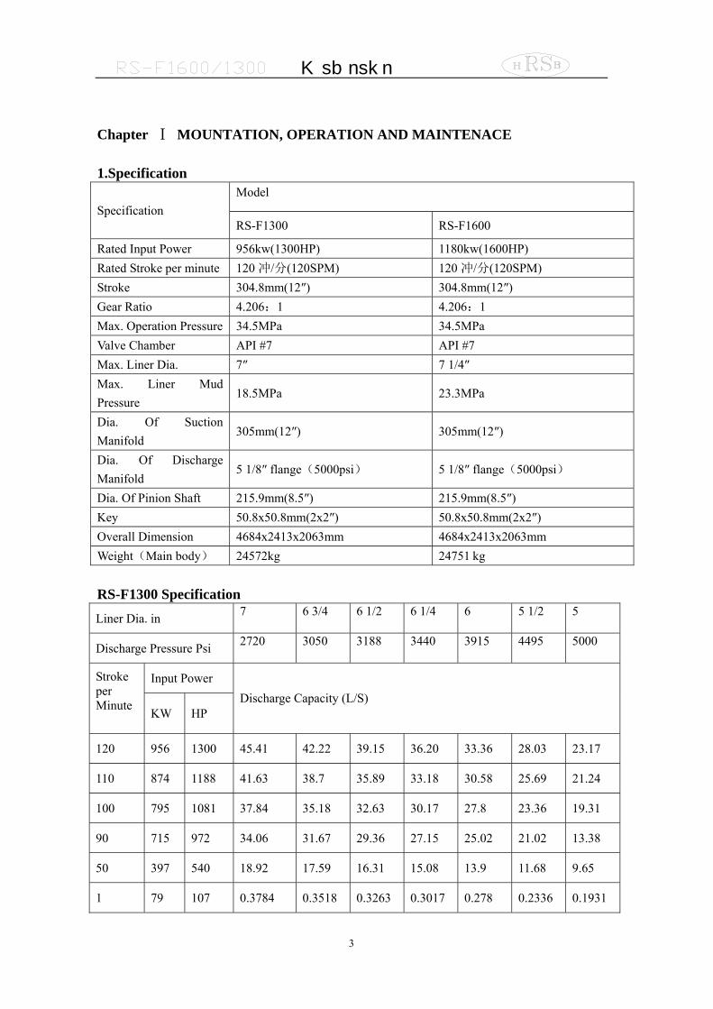
1.Specification Model
Specification RS-F1300 RS-F1600
Rated Input Power 956kw(1300HP) 1180kw(1600HP) Rated Stroke per minute 120冲/分(120SPM) 120冲/分(120SPM) Stroke 304.8mm(12″) 304.8mm(12″) Gear Ratio 4.206:1 4.206:1 Max. Operation Pressure 34.5MPa 34.5MPa Valve Chamber API #7 API #7 Max. Liner Dia. 7″ 7 1/4″ Max. Liner Mud Pressure
18.5MPa 23.3MPa
Dia. Of Suction Manifold
305mm(12″) 305mm(12″)
Dia. Of Discharge Manifold
5 1/8″ flange(5000psi) 5 1/8″ flange(5000psi)
Dia. Of Pinion Shaft 215.9mm(8.5″) 215.9mm(8.5″) Key 50.8x50.8mm(2x2″) 50.8x50.8mm(2x2″) Overall Dimension 4684x2413x2063mm 4684x2413x2063mm Weight(Main body) 24572kg 24751 kg RS-F1300 Specification
Liner Dia. in 7 6 3/4 6 1/2 6 1/4 6 5 1/2 5
Discharge Pressure Psi 2720 3050 3188 3440 3915 4495 5000
Input Power Stroke per Minute KW HP
Discharge Capacity (L/S)
120 956 1300 45.41 42.22 39.15 36.20 33.36 28.03 23.17
110 874 1188 41.63 38.7 35.89 33.18 30.58 25.69 21.24
100 795 1081 37.84 35.18 32.63 30.17 27.8 23.36 19.31
90 715 972 34.06 31.67 29.36 27.15 25.02 21.02 13.38
50 397 540 18.92 17.59 16.31 15.08 13.9 11.68 9.65
1 79 107 0.3784 0.3518 0.3263 0.3017 0.278 0.2336 0.1931
M ud p um p
4
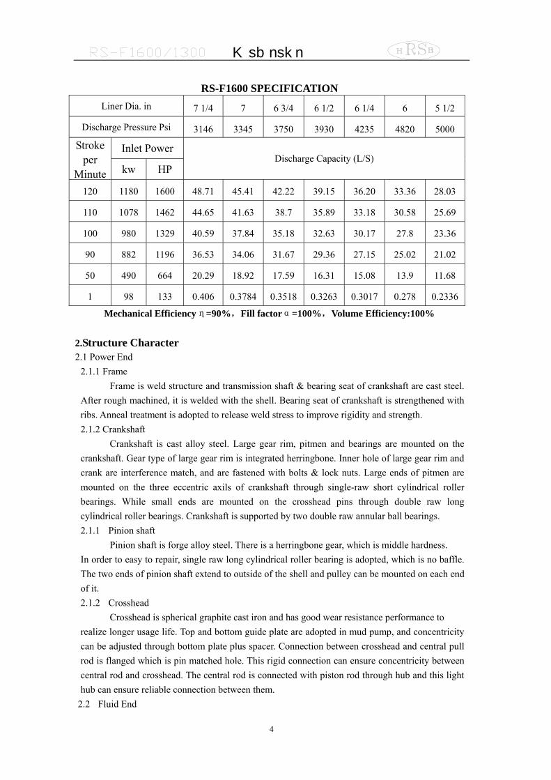
RS-F1600 SPECIFICATION
Liner Dia. in 7 1/4 7 6 3/4 6 1/2 6 1/4 6 5 1/2
Discharge Pressure Psi 3146 3345 3750 3930 4235 4820 5000
Inlet Power Stroke per
Minute kw HP Discharge Capacity (L/S)
120 1180 1600 48.71 45.41 42.22 39.15 36.20 33.36 28.03
110 1078 1462 44.65 41.63 38.7 35.89 33.18 30.58 25.69
100 980 1329 40.59 37.84 35.18 32.63 30.17 27.8 23.36
90 882 1196 36.53 34.06 31.67 29.36 27.15 25.02 21.02
50 490 664 20.29 18.92 17.59 16.31 15.08 13.9 11.68
1 98 133 0.406 0.3784 0.3518 0.3263 0.3017 0.278 0.2336
Mechanical Efficiencyη=90%,Fill factorα=100%,Volume Efficiency:100% 2.Structure Character 2.1 Power End
2.1.1 Frame Frame is weld structure and transmission shaft & bearing seat of crankshaft are cast steel.
After rough machined, it is welded with the shell. Bearing seat of crankshaft is strengthened with ribs. Anneal treatment is adopted to release weld stress to improve rigidity and strength. 2.1.2 Crankshaft
Crankshaft is cast alloy steel. Large gear rim, pitmen and bearings are mounted on the crankshaft. Gear type of large gear rim is integrated herringbone. Inner hole of large gear rim and crank are interference match, and are fastened with bolts & lock nuts. Large ends of pitmen are mounted on the three eccentric axils of crankshaft through single-raw short cylindrical roller bearings. While small ends are mounted on the crosshead pins through double raw long cylindrical roller bearings. Crankshaft is supported by two double raw annular ball bearings. 2.1.1 Pinion shaft
Pinion shaft is forge alloy steel. There is a herringbone gear, which is middle hardness. In order to easy to repair, single raw long cylindrical roller bearing is adopted, which is no baffle. The two ends of pinion shaft extend to outside of the shell and pulley can be mounted on each end of it. 2.1.2 Crosshead
Crosshead is spherical graphite cast iron and has good wear resistance performance to realize longer usage life. Top and bottom guide plate are adopted in mud pump, and concentricity can be adjusted through bottom plate plus spacer. Connection between crosshead and central pull rod is flanged which is pin matched hole. This rigid connection can ensure concentricity between central rod and crosshead. The central rod is connected with piston rod through hub and this light hub can ensure reliable connection between them.
2.2 Fluid End
M ud p um p
5
2.2.1 Cylinder Cylinder is forged by alloy steel and the three cylinders on mud pump can be exchanged.
Thorough structure design, which is valve on valve, can reduce cylinder volume and to improve volume efficiency. Cylinder surface can coated nickel to improve its corrosion resistance performance if clients require. Discharge compressor, shear pin safety valve and discharge filter screen are mounted on each discharge outlet of three cylinders. Discharge outlet is 5 1/8″5000psi flange
2.2.2 Valve Assy. API 7# valve is used both for F-1600 & F-1300 mud pump. Suction valve and discharge valve can also be exchanged.
2.2.2 Liner Liner can be processed with double metal layer which inner layer is wear resistance cast
iron with hardness HRC60~65, also has good corrosion resistance performance and finish。 2.2.3 Piston and piston rod
Piston and piston rod is sealed through cylinder surface and rubber ring. Lock nuts are used to prevent piston loosen and seal. 2.2.5 Spray System
Spray system includes spray pump, cool down water tank and spray pipe. It is used to cool and wash liner and piston to improve their usage life.
Spray pump is centrifuge pump and can be driven through belt which pulley is mounted on the extend end of the inlet shaft or electrical motor directly. Water is adopted to cool and lubricate it.
Spray pipe is mounted on the hub which connects middle pull rod and piston rod, and can move reciprocally together with piston. Cool fluid can always spray the contact surface between piston and cylinder because nozzle is very near piston. Stationary spray pipe can also be adopted and has long usage life.
2.2.6 Lubrication System Pressure lubrication combining splash lubrication is adopted for power end. Pressure oil
pumped by gear oil pump in the oil tank is transmitted to crosshead, middle pull rod, crosshead guide and bearings through lubrication pipe line. Working condition of gear oil pump can be watched from pressure gauge in the back of the shell.
2.2.7 Suction System Suction system is used for preventing air block due to low air pressure of pump inlet. Suction
system is composed by base, butterfly valve and manifold. Suction pump on the suction manifold can be driven by electrical motor or by belt on the inlet shaft of mud pump to reduce power consumption. 3. Mountation of new pump 3.1 Mountation of pump
In order to save time and power, before mounting this pump, you should give the correct program for locating the drilling pump, spray pump, suction pipe and discharge pipe line, including there direction.
The box type construction of the power frame has high resistance to bending but relatively less resistance against twist. Therefore, the support under the pump must be level and adequate to support the weight and operating forces exerted by the pump. You should place the pump on the
M ud p um p
6
level concrete foundation, so as to get the correct lubricating for power end and prevent possibility of twisting and distorting of power frame.
On permanent mountations or on barge, you must level the pump, ensure the base of pump being uniform supported. Please do not tight the foundation bolts unevenly, or unnecessary distortion will be resulted in the base of pump, and that will effect the operating of the pump. If you use v-belt to drive, you should to fix the pump by steel board and support rod, prevent the pump being moved by the force exerted with the v-belt. 3.1.1 Mountation of the drive
The drive between the mud pumps and the power source, whether V-belts or multiwidth chains, should be mounted with the greatest care to assure maximum operating life with minimum of unexpected or undesirable shutdowns due to drive failures.
The sheave can be mounted on the left or right side according to the requirement. Therefore, we can mount the sheave used for driving spray pump on the other side of the driving shaft.
When mounting the drive sheave, make sure all grease of rust preventative is removed from the shaft and the bore of the drive. Remove all burrs or rough spots from the shaft end, key, and keyway. Fit key to the keyways in the shaft and then mounting key into shaft keyway.
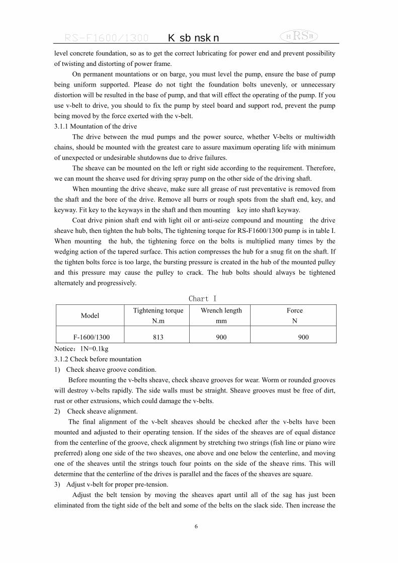
Coat drive pinion shaft end with light oil or anti-seize compound and mounting the drive sheave hub, then tighten the hub bolts, The tightening torque for RS-F1600/1300 pump is in table I. When mounting the hub, the tightening force on the bolts is multiplied many times by the wedging action of the tapered surface. This action compresses the hub for a snug fit on the shaft. If the tighten bolts force is too large, the bursting pressure is created in the hub of the mounted pulley and this pressure may cause the pulley to crack. The hub bolts should always be tightened alternately and progressively.
Chart I
Model Tightening torque
N.m Wrench length
mm Force
N
F-1600/1300 813 900 900 Notice:1N=0.1kg 3.1.2 Check before mountation 1) Check sheave groove condition.
Before mounting the v-belts sheave, check sheave grooves for wear. Worm or rounded grooves will destroy v-belts rapidly. The side walls must be straight. Sheave grooves must be free of dirt, rust or other extrusions, which could damage the v-belts. 2) Check sheave alignment.
The final alignment of the v-belt sheaves should be checked after the v-belts have been mounted and adjusted to their operating tension. If the sides of the sheaves are of equal distance from the centerline of the groove, check alignment by stretching two strings (fish line or piano wire preferred) along one side of the two sheaves, one above and one below the centerline, and moving one of the sheaves until the strings touch four points on the side of the sheave rims. This will determine that the centerline of the drives is parallel and the faces of the sheaves are square. 3) Adjust v-belt for proper pre-tension.
Adjust the belt tension by moving the sheaves apart until all of the sag has just been eliminated from the tight side of the belt and some of the belts on the slack side. Then increase the
M ud p um p
7
center distance. Do not obtain belt tension by picking up end of pump and allowing belts to tighten under
weight of pump as end is being lowered under the ground. 3.2 Suction system requirements
Individual mountation conditions will dictate the design of the suction system. The suction of the F-series pumps must have a positive head (pressure) for satisfactory performance. The optimum suction manifold pressure is 0.14~0.21Mpa (20~30psi) for maximum volumetric efficiency and expendable parts service life. This head pressure is best supplied by a 5×6 centrifugal pump with 40h.p 1150 rpm electric motor. This type of drive requires a device to automatically start and stop the centrifugal pump motor simultaneously with the triplex pump. On DC electric powered rigs, a signal can usually be supplied from the DC control panel to energize a magnetic starter. The mud pump clutch air line will provide a set of contacts for energizing the magnetic starter when clutch is engaged.
The charging pump can also be belt driven from the triplex pinion shaft charging type of drive is not as efficient at slow speeds with viscous fluids. Under some conditions, the F-series pumps may be operated without a charging pump. Provided the fluid level in mud pits is higher than the top of the liners, fluid being pumped is low viscosity and suction line must be short, straight and of at least the same diameter as suction manifold inlet.
The suction lines should be piped with valve arrangements so the charging pump can be by-passed. So, operation can be continued in event of charging pump failure or for maintenance. Operation without a charging pump can be improved by replacing the suction valve springs with a weaker spring.
The ID of suction lines could not smaller than the Id of connection lines. The lines need to be cleaned before assembled. There are not allowed any gas leakage among the suction lines, so fewer valves and elbows are better, the valves to be used have to be the same as butterfly valve. The flow-limiting valve does not allowed to be used, it will decrease the efficient of the pump.
Suction bladders are a very effective aid for complete filling of the liners and dampening pulsations in the suction line which results in a smoother flow in the discharge line.
Caution: Do not pipe the return line from the shear relief valve back into the suction system as a relief valve operation will cause a sudden pressure rise in the system vastly greater than the system rated pressure, resulting in damaging manifold, suction sladder and centrifugal pump.
The discharge bladder needs to be charged in advance. The charging pressure can be no more than 2/3 of the discharging pressure, and the max. pressure is no more than 4.5Mpa。The gas such as air and N2 can be charged in bladder, but the flammable and explosive gas such as O2 and H2 does not permitted. 4. Start and operation of the pump 4.1 Preparation before start 4.1.1 Preparation of power end
Mud pump has been completely assembled and test operated under pressure before being shipped to the field. The lubrication is drained from the power end. Before operating the pump, the following must be performed or checked:
When you start a new pump or restart a pump which has not been used for a long time, before adding lubrication into the power end, you must open inspection door in cover and check oil reservoir for possible accumulation of condensation, etc.. Drain and flush it by removing the
M ud p um p
8
pipe plugs in each side of pump & wash inner cavity of power end. Add the proper type and quantity of lubrication in the power end and some internal oil shortage positions, including the upper oil pool of pinion and gear, upper oil pool for crosshead etc., then drive the pump for several round by hands, ensure the pump get a good lubricating in time after starting the pump.
In winter: Please use 120# sulfur-phosphorous type medium EP gear oil and add 10% of 4# compounding antirust additive (Or MildEp 2# recommended by AGMA).
In summer: Please use 200# sulfur-phosphorous type medium EP gear oil and add 10% of 4#
compounding antirust additive (Or MildEp 6# recommended by AGMA). 4.1.2 Lubricant specification:
The specification of using extreme pressure(EP),non-corrosion, anti- foam lubricant following:
Environment temperature: +30Fo~ +155o F (-1℃~ +68℃ ) ,AGMA No.6#EP(320#
sulfur-phosphorous type medium EP gear oil and add 10% of 4# compounding antirust additive) Environment temperature: 0 Fo~+80o F (-18℃~+27℃ ) ,AGMA No.4#EP (220#
sulfur-phosphorous type medium EP gear oil and add 10% of 4# compounding antirust additive) Environment temperature: -20 Fo~+40o F (-29℃~+4℃ ) ,AGMA No.1#EP (150#
sulfur-phosphorous type medium EP gear oil and add 10% of 4# compounding antirust additive) 4.1.3 Oil quantity: About 379 liter(100gal.).
Recheck oil level after pump has operated for a period of 15 minutes. Shut pump down and allow approximately five minutes for the oil level to equalize. Check oil level gauge. It is usually necessary for a few more gallons (about 10 gallons) of oil to be added due to a certain amount being retained in crosshead area and frame cavities. 4.2 Preparation of fluid end. 4.2.1 Check the cylinder, piston and valve of fluid end, ensure they have been assembled correctly. Check if the discharge valve of drilling pump is opened.
Before starting the pump, you must fill the cylinder with mud or water, in case of the air cavity being taken place. For the pump which the air cavity taking place, you can not eliminate the air cavity under pressure, you must open the valve to pump and run the pump in “small circulating” until all the air have been eliminated. In this case, it can ensure that the pump runs smoothly and the service life of the pump will be longer. 4.2.2 Check the safe pin, ensure the pin have been inserted to the proper pin hole of cylinder for a special pressure. See the indication of safe valve in details. 4.2.3 The spray pump must be started before the pump starting or simultaneously, in case of damaging piston and cylinder. Before starting the centrifugal spray pump, you must fill up the pump body with liquid in case of the air cavity being taken place. 4.3 The operation after start
The rotating speed should be increased slowly, therefore the increase of flowing speed of liquid in suction line can follow the speed of piston and the air cavity will be not taken place.
Under the natural suction, the highest speed of the pump is determined by the fill factor in the stroke length, this limited speed is different in different cases, which is changed according to the design and efficient pressure head and is still determined by the mud (such as gravity, viscosity of mud and the air quantity in the mud). Operator can judge the running condition of the pump (good or the air cavity having been taken place or the suction condition is
M ud p um p
9
not good), so as to take measures in time. For all bearings of power end, check if the temperature of guide plate of crosshead is too high
and there is unusual sound or phenomenon at this position. Usually, the rising of oil temperature is less than 45℃.
5. Lubrication 5.1 Proper lubrication of the moving parts in any piece of machinery is the most important single factor affecting its ultimate life. To obtain maximum trouble-free service life from the power end of the pump, it is necessary to perform routine maintenance care and inspection to insure the proper amount of clean lubricant is being provided.
The RS-F1600/1300 mud pump utilizes the controlled flow oil bath splash and pressure system to lubricate the entire power end. The gear pump placed in the oil bank provides the pressure oil to crosshead, extension rod, guide plate of crosshead and all bearings of the pump through oil line individually, so as to obtain the compulsory lubrication for the pump. The working condition of the gear pump can be seen from the pressure gauge at rear end of the pump frame.
The splash lubricating system bring the oil from oil pool by the gear, when the gear and opinion is meshing, the oil is splashed to the oil pool of upper plate at the middle section, then flow to the two bearings of driving shaft and crankshaft respectively. 5.2 The pressure lubricating modes of power end limit the min. stroke of pump. If only lubricating main bearing and pinion bearing, the min. stroke is 40 spm. However, in order to lubricate the crosshead and so on, the min. pressure of lube oil is 0.035Mpa (5 psi), then the min. stroke is 25 spm when pump is operating. So, the min. stroke RS-F1600/1300 is 25 spm.
When the pump is operating, you must perform the routine lube oil level inspection every shift for the main shaft box, ensure it is at the full position of the oil level gauge. 5.3 Check the following items as the lube oil pressure decreased:
—— Whether the strainer has been jammed.
—— Whether the level of lube oil is lower.
—— Whether V-belts are skid or not(out board gear petrolift)
—— Whether the connectors are loosed or cracked.
—— Whether the petrolift is worn out or cracked.
——Whether the over flow is failure
Check the following items as the lube oil pressure increased abnormally:
—— Whether the oil passages has been jammed.
—— Whether the sediment makes the lube oil sticking.
—— Whether the over flow is failure.
—— Whether the pressure gauge is failure. —— other situations
5.4 There are desilters at two sides of the crosshead of power end. The oil splashed to the oil pool

M ud p um p
10
should be deposited. The oil discharge cover is at the two sides of pump frame under the inspecting door of crosshead and it should be checked once a month. When checking, open the oil discharge cover on the two sides and discharge the sediment from desilters. The operation will loss about 15 gallon of lube oil, so you then should add certain quantity of lube oil. Check it once per 6 months. All oil must be let out if there is some grind chip or corrosive compound in it. And then the oil pool is washed and refilled with new oil. The outlets are at both sides and back of frame. When washing, every oil grooves and oil chamber on crosshead guide plate must be cleaned thoroughly. Lubricant condition must be checked termly. The lube oil will be changed often when the infiltration of humidity, vapor, dust and mud occurs. 6. Spray pump device Spray pump device consists of centrifugal spray pump, water tank, spray hose, etc.. It is used for washing and cooling the liner and piston during pump running. The pump frame must be full-filled with fluid before centrifugal spray pump running in order to avoid air pocket. The 5-drop per minute of sealing stuffing is available, and then it will lubricate the stuffing and prolong the stuffing life. Both mud pump pinion shaft through belt and electromotor can drive centrifugal spray pump. Pump’s lift: 11M, flux: 13M3/h. Customers can decide other type of drive when they order. It is important all the time that the coolant must be applied as mush as possible to the liners and piston. Any break of coolant will destroy the piston rubber and the liners at once. The liners’ coolant is water or water base coolant with antirust. The spray pump must be started before mud pump or simultaneously to avoid damage of piston and liners. The spray pipes should often be checked to assure the coolant fluid spray on piston directly. The coolant fluid is exported from water tank to spray hose. After cooling the liners and pistons, the coolant fluid will be discharged from liners to water tank’s deposit chamber. When the coolant overflows from filtering net, the mud, etc (solid phrase) will deposit and filters will block the sundries. Often check the coolant fluid’s clean condition. Clean and wash water tank & change the coolant fluid according to requirement. The liners and pistons will be worn out early and the spray pipe will be blocked because of the sand in polluted fluid. 7. Maintenance 7.1 Daily maintenance
7.1.1 Check the oil level of power end per shift after stopping pump running. 7.1.2 Pay attention to liners and pistons working condition. It is normal that some short-circuit
mud comes through and it does not mean the wear and tear of liners and pistons. Liners’ symmetrical wear is also pistons’ wear; this condition can be continued unless the short-circuit mud is very obvious or excess normal degree.
7.1.3 Check the coolant fluid of liners and pistons to supply it if there is lack of coolant. If the dirty coolant is dirt, change it because dirty coolant will sharpen the wear of cooling pump and shorten the pump’s life.
7.1.4 Check the liners’ nozzle daily to avoid block of nozzle and ensure adequate cooling and lubricant supplement to liners and pistons.
7.1.5 After assembly, re-check tighten moment of piston clamp after first several hours running.
M ud p um p
11
7.1.6 Loose the piston rod clamp daily, turn the piston quarter round and then tighten the clamp in order to make piston wearing surface symmetrically and prolong the life of liners and pistons.
7.1.7 Check pulsation’s discharging pressure once everyday to ensure that the air charge meet the requirements.
7.2 Weekly maintenance 7.2.1 Open the cap of valve box, clean the sundries on cap screws and cap flange screws and then
coat a layer of thread oil on it to avoid screw abrasion, scrape and bad mesh (lead base thread oil is advised).
7.2.2 Check valve rods’ rubber guide sleeves. Change them if they wear out. Not-round or
ellipse guide sleeve will make bad valve guide guiding function and increase the valves abrasion.
7.2.3 Check valves and valve seats abrasion condition and change the wear-out or damaged seats. Tighten the valve nuts if they are loose.
7.2.4 Change the liners and pistons if they are worn out or damaged 7.2.5 Change the pistons’ locking nuts if they are damaged, rust or unable to lock. 7.3 Monthly maintenance 7.3.1 Let out the dirty oil in the deposit pool of power end (under the crosshead) every six
months and clean it, then re-fill it with new oil. 7.3.2 Check the seals of power end. Change them if they are damaged. Tighten the loose bolt
(especially the big pulley’s bolts are important) 7.3.3 Check the gap between the guide plate and crosshead every six months. Adjust it if the gap
is too large. 7.3.4 Check the entire double end bolts and nuts’ tightness degree of fluid end including cap
flange to cylinder, cylinder to frame, liner seat to cylinder. 7.4 Annual maintenance
Check the tightness of crankshaft bearing, connecting rod bearing, transmit shaft bearing, crosshead bearing, cross guide plate every one or two years. Check the pump thoroughly and correct it if there is any loose.
8. Storage 8.1 Power end:
If the pump needs to be packed for over half months, following procedures must be done. Block up the fluid end and make the pump lean to power end, empty the oil grooves and then deposit pool and clean them.
8.2 Disassemble valves, pistons, piston rod and liners. Clean up totally inner parts of cylinders and all parts and coat the cylinder valves and parts with rust-assistant grease. Clean up the
liner spray system and liner chamber. Inject some lubricant into liner spray system avoiding rust.
8.3 Check the pump monthly and rotate the gear once. Recoat antirust oil if it is necessary. 8.4 Re-start after storage: 8.4.1 Whatever the pump that used in site or new pump just manufactured must be checked
thoroughly for damaged parts or proper assembly if it has been stored for a period and
M ud p um p
12
need to re-start. The serious accident will happen if following important things are neglected.
8.4.2 Open the covers of power end and fluid end and check the pump thoroughly. Clean all parts, machining surface and bearings to ensure that all the parts are clean and good. Add lubricant oil into power end to the specified level. Add the oil into lubricant dispatch grooves and make the oil flow into bearings.
8.4.3 Valves, pistons, liners and all parts of fluid end must be mounted properly and have a good condition. The bolts, nuts and universal joints should be tightened.
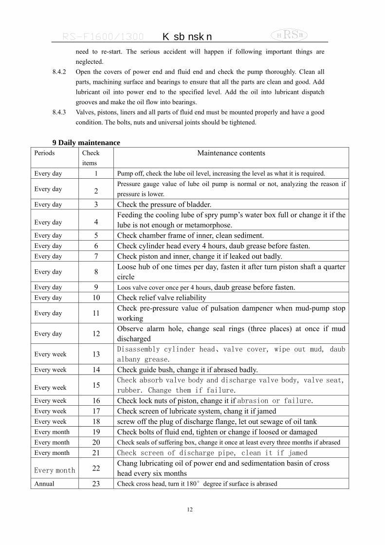
9 Daily maintenance
Periods Check items
Maintenance contents
Every day 1 Pump off, check the lube oil level, increasing the level as what it is required.
Every day 2 Pressure gauge value of lube oil pump is normal or not, analyzing the reason if pressure is lower.
Every day 3 Check the pressure of bladder.
Every day 4 Feeding the cooling lube of spry pump’s water box full or change it if the lube is not enough or metamorphose.
Every day 5 Check chamber frame of inner, clean sediment. Every day 6 Check cylinder head every 4 hours, daub grease before fasten. Every day 7 Check piston and inner, change it if leaked out badly.
Every day 8 Loose hub of one times per day, fasten it after turn piston shaft a quarter circle
Every day 9 Loos valve cover once per 4 hours, daub grease before fasten. Every day 10 Check relief valve reliability
Every day 11 Check pre-pressure value of pulsation dampener when mud-pump stop working
Every day 12 Observe alarm hole, change seal rings (three places) at once if mud discharged
Every week 13 Disassembly cylinder head、valve cover, wipe out mud, daub
albany grease. Every week 14 Check guide bush, change it if abrased badly.
Every week 15 Check absorb valve body and discharge valve body, valve seat,
rubber. Change them if failure. Every week 16 Check lock nuts of piston, change it if abrasion or failure. Every week 17 Check screen of lubricate system, chang it if jamed Every week 18 screw off the plug of discharge flange, let out sewage of oil tank Every month 19 Check bolts of fluid end, tighten or change if loosed or damaged Every month 20 Check seals of suffering box, change it once at least every three months if abrased Every month 21 Check screen of discharge pipe, clean it if jamed
Every month 22 Chang lubricating oil of power end and sedimentation basin of cross head every six months
Annual 23 Check cross head, turn it 180°degree if surface is abrased

M ud p um p
13
Annual 24 Check slide, adjust it if loosed. Check clearance of cross head, adjust it if not meet the requirements
Annual 25 Check the surface of pinion shaft and crank shaft, use another gear’s sideIf necessary
Annual 26 Check the assembly of pinion shaft and crank shaft, solve it if have problems Annual 27 Check the bearing of power end, change it if damaged
Annual 28 Check the seal of up rear wall plate and crank shaft cover etc. change it ifsealing failure.

M ud p um p
14
CHAPTER II MAINTENANCE MANUAL
M ud p um p
15
1. Power end
1.1 Maintenance of power end Routine inspection of the power end is the most important form of preventive maintenance and
will result in considerable savings by detecting any major trouble that might be developing and allowing the necessary repairs to be made on a planned or normal rig-down time. 1.1.1 Check tighten torque of the main-part bolts.
The tighten torque of the main-part bolts is 13210 N.m (9750ft.lbs) 1.1.2 Safety wires: Check safety wires on all bolts and replace any broken wires after
retightening the bolts. 1.1.3 Oil lines: Check all oil lines to insure they are intact and free of obstructions. Check oil
pump suction hose for damage or flat areas. 1.1.4 Suction filter: Check condition of suction filter. Clean and replace if necessary. 1.1.5 Main bearing cover: remove the main bearing cover and check tightness of main bearing
retainer bolts and the bearing rollers, etc. Clean and remove any sludge or foreign substance that might have accumulated at the bottom of the bearing area.
1.1.6 Main gear and pinion teeth: Inspect the teeth of the main gear and pinion gear for any indications of abnormal wear. During the initial break-in period there will be some pitting on the face of the gear teeth. This is referred to as “initial pitting” and is no harmful to the life of the gear. In normal inspection, if the pitting continues to increase, immediately contact the pump manufacturer for a more thorough inspection of the gear.
1.1.7 Crosshead pin bolts and crosshead guides: disassembly the crosshead guides, check the crosshead pin bolts and safety wires(you can disassembly the up rear wall plate and turn the pitman at the outside stop point when checking the crosshead pin). Use the torque wrench to tighten the crosshead pin bolts, the tighten torque is no more than 225~240N.m(165~175ft. lbs).Because it may cause damage to the bearing and other parts, the crosshead or guides should be replaced immediately if they show abnormal wear. Excessive wear can also cause rapid wear of piston and cylinder liner.
1.1.8 Oil and oil reservoir: Check the oil and cleanliness of the oil tank. Maintain the service oil system as described in the Lubrication Section of this manual.
Assembly of power end
2.1Roller bearings 2.1.1 All inner and outer races are assembled by means of very accurate fits. This accuracy is
necessary. Therefore, if the bearings are to be used again, the inner and outer races and the roller assemblies of each bearing must be kept together, and remounted exactly as they came off.
2.1.2 It is always necessary to completely replace any roller bearing that fails, even though only one part of the bearing shows damage. Excessive clearances, worn or grooved raceways and any pitting or flaking of the parts is indicative of failure and the entire bearing should be
M ud p um p
16
changed as soon as possible. All roller bearings are assembled to their shafts by means of shrink fits. Damaged or worn
bearings and raceways can be removed from the shaft with a bar and hammer. They can be cut from the shaft with a burning torch very carefully not to burn in to the shaft. Bearings should always be heated in the oil bath and the temperature should not exceed 149℃ (300℉). Be certain that both the oil and the container must be very clean.
Once the heated bearing is mounted on the shaft, hold it in place until it cools naturally. NEVER USE WATER OR ANY OTHER LIQUID TO COOL A HOT BEARING, or the bearing and rollers will be cracked and the bearing will fail immediately.
Never strike a roller bearing with a steel hammer. If the bearing must be driven into position, use wood or a soft hammer and strike lightly.
Always lubricate the shaft or hole before mounting the bearing. Do not remove a new bearing from the box or unwrapping until it is to be mounted. Protect it
from dirt and other foreign matter at all times. If a bearing must be cleaned, use clean kerosene or other solvent.
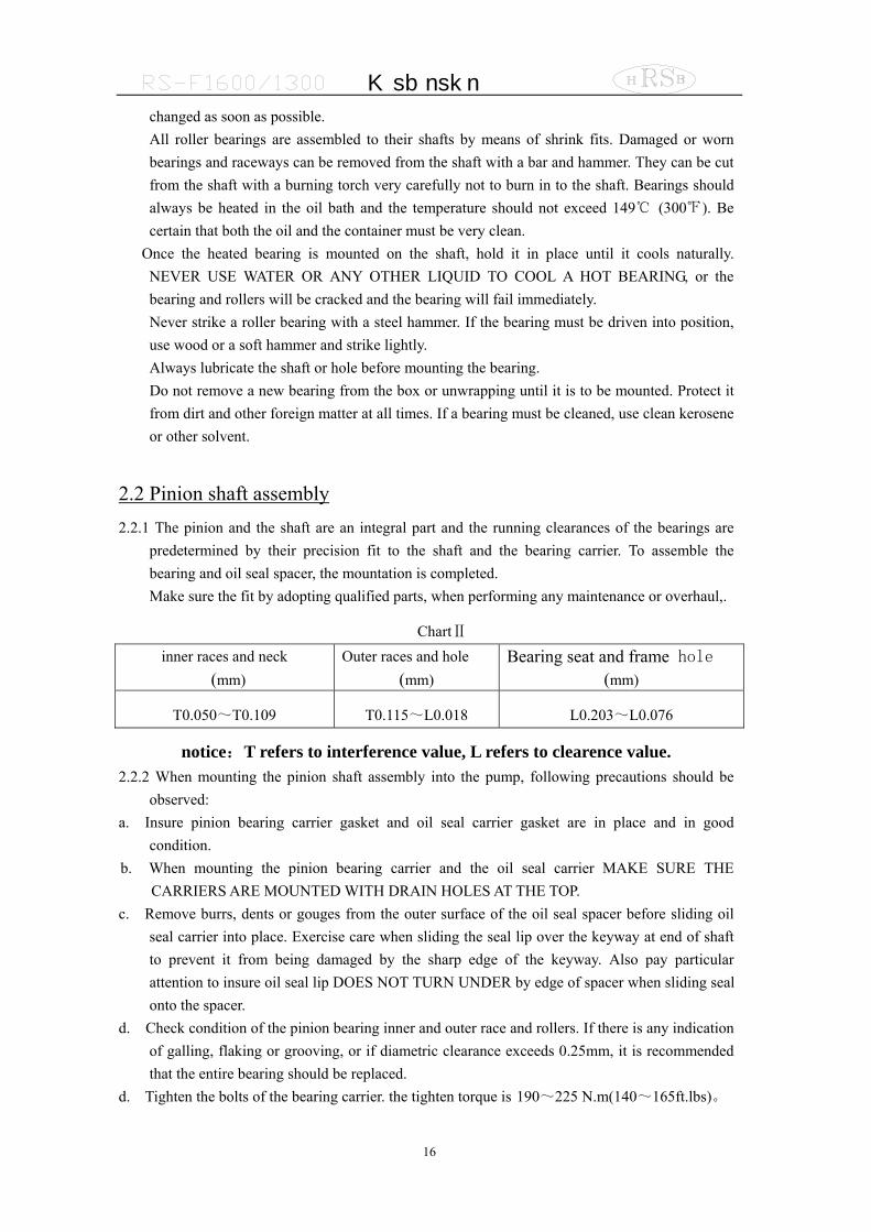
2.2 Pinion shaft assembly 2.2.1 The pinion and the shaft are an integral part and the running clearances of the bearings are
predetermined by their precision fit to the shaft and the bearing carrier. To assemble the bearing and oil seal spacer, the mountation is completed. Make sure the fit by adopting qualified parts, when performing any maintenance or overhaul,.
ChartⅡ inner races and neck
(mm) Outer races and hole
(mm) Bearing seat and frame hole
(mm)
T0.050~T0.109 T0.115~L0.018 L0.203~L0.076
notice:T refers to interference value, L refers to clearence value. 2.2.2 When mounting the pinion shaft assembly into the pump, following precautions should be
observed: a. Insure pinion bearing carrier gasket and oil seal carrier gasket are in place and in good
condition. b. When mounting the pinion bearing carrier and the oil seal carrier MAKE SURE THE
CARRIERS ARE MOUNTED WITH DRAIN HOLES AT THE TOP. c. Remove burrs, dents or gouges from the outer surface of the oil seal spacer before sliding oil
seal carrier into place. Exercise care when sliding the seal lip over the keyway at end of shaft to prevent it from being damaged by the sharp edge of the keyway. Also pay particular attention to insure oil seal lip DOES NOT TURN UNDER by edge of spacer when sliding seal onto the spacer.
d. Check condition of the pinion bearing inner and outer race and rollers. If there is any indication of galling, flaking or grooving, or if diametric clearance exceeds 0.25mm, it is recommended that the entire bearing should be replaced.
d. Tighten the bolts of the bearing carrier. the tighten torque is 190~225 N.m(140~165ft.lbs)。
M ud p um p
17
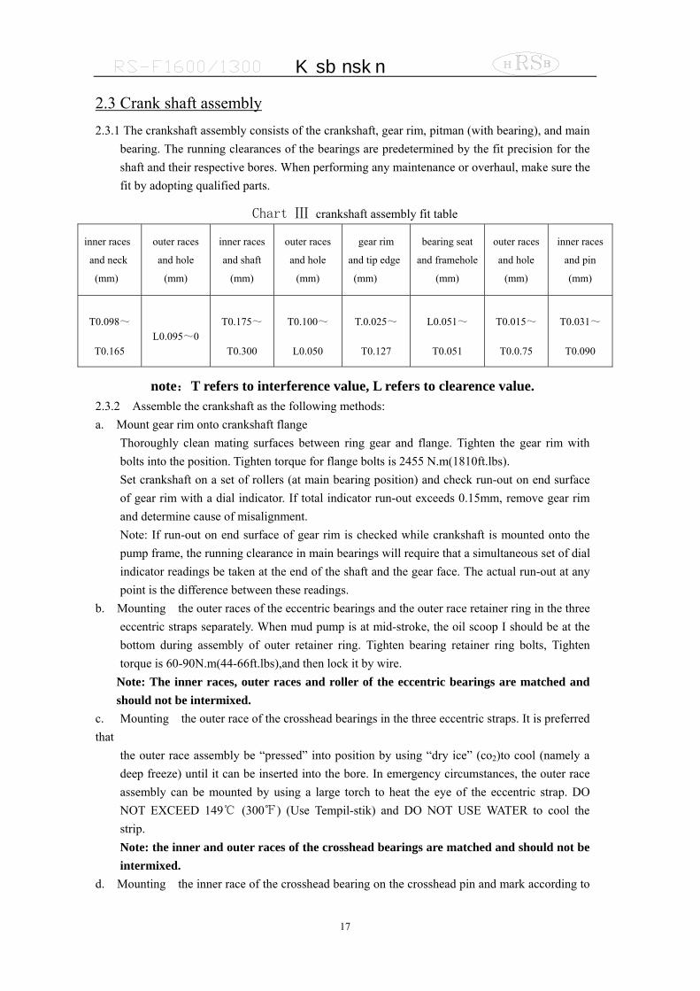
2.3 Crank shaft assembly 2.3.1 The crankshaft assembly consists of the crankshaft, gear rim, pitman (with bearing), and main
bearing. The running clearances of the bearings are predetermined by the fit precision for the shaft and their respective bores. When performing any maintenance or overhaul, make sure the fit by adopting qualified parts.
Chart Ⅲ crankshaft assembly fit table
inner races
and neck
(mm)
outer races
and hole
(mm)
inner races
and shaft
(mm)
outer races
and hole
(mm)
gear rim
and tip edge
(mm)
bearing seat
and framehole
(mm)
outer races
and hole
(mm)
inner races
and pin
(mm)
T0.098~
T0.165 L0.095~0
T0.175~
T0.300
T0.100~
L0.050
T.0.025~
T0.127
L0.051~
T0.051
T0.015~
T0.0.75
T0.031~
T0.090
note:T refers to interference value, L refers to clearence value. 2.3.2 Assemble the crankshaft as the following methods: a. Mount gear rim onto crankshaft flange Thoroughly clean mating surfaces between ring gear and flange. Tighten the gear rim with
bolts into the position. Tighten torque for flange bolts is 2455 N.m(1810ft.lbs). Set crankshaft on a set of rollers (at main bearing position) and check run-out on end surface of gear rim with a dial indicator. If total indicator run-out exceeds 0.15mm, remove gear rim and determine cause of misalignment. Note: If run-out on end surface of gear rim is checked while crankshaft is mounted onto the pump frame, the running clearance in main bearings will require that a simultaneous set of dial indicator readings be taken at the end of the shaft and the gear face. The actual run-out at any point is the difference between these readings.
b. Mounting the outer races of the eccentric bearings and the outer race retainer ring in the three eccentric straps separately. When mud pump is at mid-stroke, the oil scoop I should be at the bottom during assembly of outer retainer ring. Tighten bearing retainer ring bolts, Tighten torque is 60-90N.m(44-66ft.lbs),and then lock it by wire.
Note: The inner races, outer races and roller of the eccentric bearings are matched and should not be intermixed.
c. Mounting the outer race of the crosshead bearings in the three eccentric straps. It is preferred that
the outer race assembly be “pressed” into position by using “dry ice” (co2)to cool (namely a deep freeze) until it can be inserted into the bore. In emergency circumstances, the outer race assembly can be mounted by using a large torch to heat the eye of the eccentric strap. DO NOT EXCEED 149℃ (300℉) (Use Tempil-stik) and DO NOT USE WATER to cool the strip. Note: the inner and outer races of the crosshead bearings are matched and should not be intermixed.
d. Mounting the inner race of the crosshead bearing on the crosshead pin and mark according to
M ud p um p
18
their respective eccentric strap positions. remove all of burrs and scratching before mounting . Note: The inner and outer races are matched and must not be intermixed. fit toleranceto see table III.
e. Mounting the strainer ring into the groove of the right eccentric shaft. Mounting the inner races into . the shaft wobbler, then mounting the inner bearing strainer ring after mounting pitman. Tighten torque is 60~90 N.m(44~66ft.lbs).
f. Mounting left and right eccentric strap with the same procedure outlined in step 5 above. 2.3.3 Mounting crankshaft parts into the frame, the assembly procedure is as following: a. Place a piece of wood between eye of eccentric strap and crosshead guide plate to protect guide
plate from scoring or gouging as the straps are sliding into position. b. Rotate the main bearing so that the locating pin of crankshaft bottom seat inserts into the
locating hole of crankshaft. c. After mounting the crank shaft into frame, inspect the rollers of main bearing to make sure the
load of each line in each side is same before mounting the main bearing cover, floating bearing seat fixed in right position can make the load same in each side. Thus, the inner and outer rollers which support the weight of shaft has the same numbers and can be fixed.
d. Insert shims under the main bearing caps to obtain 0.10mm (0.004″) clamp. The pre-load is obtained by placing the correct amount of shims under the main bearing cap.
e. Check the load of the rollers on both sides again (as above described to make sure the load of
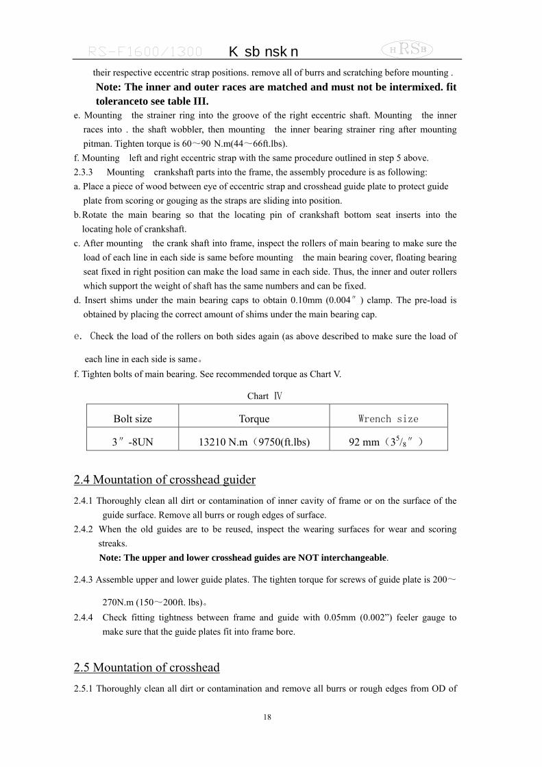
each line in each side is same。 f. Tighten bolts of main bearing. See recommended torque as Chart V.
Chart Ⅳ
Bolt size Torque Wrench size
3″-8UN 13210 N.m(9750(ft.lbs) 92 mm(35/8″)
2.4 Mountation of crosshead guider 2.4.1 Thoroughly clean all dirt or contamination of inner cavity of frame or on the surface of the
guide surface. Remove all burrs or rough edges of surface. 2.4.2 When the old guides are to be reused, inspect the wearing surfaces for wear and scoring
streaks. Note: The upper and lower crosshead guides are NOT interchangeable.
2.4.3 Assemble upper and lower guide plates. The tighten torque for screws of guide plate is 200~
270N.m (150~200ft. lbs)。 2.4.4 Check fitting tightness between frame and guide with 0.05mm (0.002”) feeler gauge to
make sure that the guide plates fit into frame bore.
2.5 Mountation of crosshead 2.5.1 Thoroughly clean all dirt or contamination and remove all burrs or rough edges from OD of
M ud p um p
19
the crosshead, crosshead pin bores, and inner bore of crosshead guide plates. Dry crosshead pin bore so that they form metal-to-metal contact.
2.5.2 Let “eye” of eccentric strap at the opening in the side of the crosshead guide. Block eccentric strap so that crosshead will clear the “eye” as it is sliding into position to where the crosshead pinholes are in alignment.
2.5.3 Mounting the left side crosshead first and then rotate eccentric assembly to move “eye” into center crosshead. At the time, the right hand eccentric strap “eye” back to afford clearance to mount center pin through right hand crosshead inspection door. Remove diaphragm stuffing box plate and mount right hand crosshead through this bore. Slide the crosshead into the place and then mount crosshead pin. Note: If old crossheads are to be reused, inspect the sliding surface for wear or scoring. If
necessary, mount the crossheads to opposite sides of the pump, namely the left and right crosshead could be adjusted and mounted to the hole. Before the crosshead pin retainer plate is not mounted into tapered hole, do not mount the crosshead pin into the
2.5.3 Mounting crosshead pin retainer and bolt. Rotate the crosshead pins until the four crosshead retainers and crosshead boltholes are in alignment. Mounting the crosshead retainer to crosshead bolts and tighten them by hand. Tap the bigger end of the crosshead pin in order to mount it into the taper hole. Tighten bolts and safety wire. The torque wrench has to be used. The torque is 225~240N.m(165~175ft.lbs).
Note: steps of pull out the crosshead pins: unload four retainer bolts, tighten two of them into “blind” screw hole until pins is loosed. Disassemble crosshead
2.5.4 Check running clearance of crosshead by inserting long “feeler” gauges between top surface of crosshead and crosshead guide plate. The clearance should not be less than 0.508mm (0.020”). Check entire surface of crosshead with long feeler gauge.
Note: When tighten the bolts of crosshead pin retainer excessively, it will caused the bolts protrusive and result in the running clearance of crosshead too small.
Note: you need to inspect whether the glide surface of crosshead is worn out, Assemble the crosshead in the pump opposite; namely, exchange the position of left and right crosshead if necessary, and turn it 180°to make the smooth surface at the bottom of crosshead. The middle crosshead can be used after turning 180°, Then the crosshead pin need to be assembled in the opposite position.
2.6 Checking crosshead alignment In order to make the piston running correctly in the liner, the crosshead must run linear along
the horizontal axis of cross head hole inside the frame. Inspecting and adjusting the alignment of crosshead as following: 2.6.1 Remove extension rod stuffing box seals from the diaphragm plate, but do not remove the
retainer plate. 2.6.2 Put crosshead at the extreme front of its stroke. With inside calipers or telescoping gauges,
accurately measure the distance between the extension rod and the retainer plate at the top and bottom. Compare the two measurements to determine the position of the rod relative to the centerline of the bore.
2.6.3 Rotate pump to extreme rear of stroke and do measurement again at the same place. Compare these measurements to the ones taken at the front of the stroke to determine if
M ud p um p
20
crosshead is running horizontal. 2.6.4 If the concentricity of the extension rod is 0.381mm(0.015”) lower under bottom of the
retainer plate, shims should be inserted under the lower guide plate to bring the extension rod back to center. Provided there is enough clearance between the top of crosshead and the upper guide plate, above adjustment can be done. Because of the angle of the eccentric strap, it is normal for the lower guide plate with large force at the rear due to heavier loading at this point. It is permissible to shim the guides on a taper if it has provided firm support for the guide. In the process of setting the guide plate washers,Do not make the clearance between the top of crosshead and the guide plate smaller than 0.05mm (0.020″)。Allowed much more clearance existing,it is decided by the running characteristic of three cylinder,the pressure
of crosshead always acts on the lower guide plate. Note:The clearance between the crosshead and the guide plate must be in the rang of 0.45~
0.55mm (0.0177~0.0217″)。
2.6.5 The length of washer is cut enough to make it through the guide plate completely, and it’s sides should be cut to salient the support parts of the frame.
1.8 Mountation of crosshead extension rods and extension rod stuffing box
seals 1.8.1 Rotate pump so that crosshead is at the front of the stroke. Thoroughly clean the front of
the crosshead and the end face of the crosshead extension rod. Insert the alignment boss on the end face of crosshead extension rod into the crosshead bore and tighten the retainer bolts , The tighten torque is 475~500N.m(350~370ft.lbs). Lock them by Φ3 iron wire.
1.8.2 Mountation of extension rod stuffing box seals: a. Thoroughly clean the stuffing box and coat the extension rod with light oil in order that
the seal assembly could be mounted easily. b. Remove the pressure spring from double-lip oil seal and place seal on the crosshead
middle extension rod with main lip toward power end. Replace the pressure spring into the seals lip and slide them into the stuffing box.
c. Mount the smaller O-ring into oil seal ring. Insert them onto the crosshead middle extension rod and slide them into the stuffing box bore.
d. Mounting the other bigger O-ring into the stuffing box bore. e. Mounting the double-lip oil seals that are near driving end. The method and procedure is
the same as above. f. Mounting the locking spring.
Note:the double lips seal near the power end can be replaced by the single lip seal, but in
the fluid end, the single lip seal can not be used.
M ud p um p
21
2. Fluid end
2.1 Maintenance of fluid end For many years, the fluid end of a pump was considered a non-wearing part which did not
cause ay concern other than possible infrequent repairs or replacements resulting from fluid cuts or washouts. However, the higher pressures of the present-day drilling requirements have resulted in higher stresses being imposed on the fluid end which, when combined with the corrosive characteristics of the drilling fluid, have resulted in the demand that more and better maintenance be given to the fluid end parts and pieces if a reasonable operating life is to be obtained. A few of the obvious points are as follows:
a. Make sure all valves on the discharge side of pump are opened before pump is put into operation. When valves are closed, the pump frame will bear large striking stress and this can often be the start of a fatigue crack. A small crack could occur and start the process of corrosion fatigue failure.
b. Do not engage pump clutch when prime mover is running at a high rate of speed. To do so can cause undesirable shock loads against both power end and fluid end.
c. Properly maintain pressure relief valve to assure that it can be opened when mud pump exceeds the adjusting pressure.
d. Do not operate the pump for a long time if a severe fluid knock happens. e. Properly maintain the fluid end. When pump is to be shut down or not operated for a
period of ten days or more, it is recommended that the fluid end parts such as liners, pistons, rods, etc., be removed from the pump and the fluid end flushed out completely with fresh water. After a thorough flushing and wiping, coat grease to all of the machined surfaces, such valve pot cover threads, valve pot cover gasket surfaces, valve seats, liner bores, etc., and the parts removed from the pump including liners, piston, piston rods, etc. for protection. This will not only extend the service life of the fluid end by anti-corrosion, but also protect the expendable parts and maintain them in good condition for mountation in the pump at the next start-up period.
2.2 The other things need to be pay attention to in the maintenance
process. a The cone has to be cleaned before assembling the hub between the middle pony rod and piston. b The seal ring of liner has also to be changed together when changing the liner. c The mud inside the valve and the liner has to be discharged completely and cleaned after the mud
pump does not run in winter. d Each check hole should be covered very well in order to prevent dust and sand from mixing with
the lubricant.
2.3 Assembly of fluid end Most parts of the fluid end are designed as metal to metal assembling,that will
reduce the abrasion that the high pressure fluid caused. Because of this reason,all of the parts has to be cleaned and no some defects that effect quality like burrs, nicks and rust before
M ud p um p
22
assembling to ensure the sealing of the fluid end reliably. 2.3.1 Piston rod
Clean piston and piston rod to ensure that there is no burrs and scuffing. There is a sealing ring between the piston core rod and the piston shoulder. Before mounting the piston assembly onto the piston rod, mounting O-ring first and let it into the sealing groove of the piston. When mounting the piston into the piston rod, pay attention to prevent the O-ring from sliding from the groove. And then tighten the nuts of the piston rod. The torque is 1625~2165N.m (1200~1600ft.lbs).
Inspect the end of piston rod and pony rod to make sure the surface clean and no burrs. Greasing the inner surface of liner and the outer surface of piston, mounting the piston rod in the liner to make the piston rod alignment,then use the special tools to mount the piston in the liner. Note, the locating shoulder of the piston rod end can not be damaged, it can support the piston rod to make it into the gauge hole. When the locking nut is damaged or the nylon material cannot clamp the screw and is loosing, it must be changed. Otherwise, it will lead to the damage of the piston rod and the cylinder sleeve.
2.3.2 Piston and Cylinder sleeve Mounting the seal ring of wear plate into the counterbore of fluid end,and then
mounting the bolts. Mounting the liner flange,to make sure the start point at the down right conner, the same as 5’clock position of the dial plate, using the wrench to tighten it, the torque is 640~690N.m (470~510ft.lbs).
Mounting the seal ring of liner into the counterbore of wear plate. Greasing a thin layer lubricant on the inner surface of the liner gland, and then mounting it from the rear end. Mounting the two half lock ring of liner into the liner groove, using the ″O″to clamp the two half lock ring. Using the hanger to hang the liner. Greasing the thread在 of the liner gland, To make sure the position of start point the same as 7’clock position of the dial plate when tightening the thread of the liner gland, mounting the liner into liner flang, tightening the liner gland.
When only changing the piston rubber bowl, it is ok to disassemble the stretch-retaining ring and the press plate at the front end of the piston core rod. There is no necessary to disassemble the piston core rod from the piston rod.
When changing the whole piston assembly, disassemble the locking nuts of the piston and then take out of the piston core rod from the piston rod.
Inspect the cylinder sleeve hole and ensure that there is no eyewinkers that may lead to early abrasion between the cylinder sleeve and the piston. For ensure that there is metal-to-metal contact between the cylinder sleeve and the fluid end.
Coat the thin grease or the lubricating oil on the cylinder hole surface of fluid end. Then push the cylinder sleeve into the hole until the cylinder sleeve shoulder and the fluid end shoulder become the contact of metal-to-metal.
Coat the grease on the inner hole of the cylinder sleeve and the outer surface of the piston. Inspect the end of the pull rod and the piston rod to ensure them clean
without any burrs. Push the piston rod through the cylinder sleeve. Then match the piston rod to the center of the back of the cylinder sleeve and underlay it with the hard wood. Beat the piston into the cylinder sleeve by hammer or special tool. Pay attention: when the piston rod is
M ud p um p
23
near to the crosshead push rod, the location bulging of the front end of the piston rod should not be damaged. The piston rod must hold out and enter into the location hole.
2.3.3 Valve and valve seat Take out of three valve covers, three cylinder heads and plugs. Clean completely each machined surface of fluid end with the high-grade solvent.
Make sure each valve seat hole clean and dry without any dirt, grease and antirust. Polish all burrs on the surface with carborundum paper. The carborndum paper should do circle movement along the valve seat hole.
Clean and dry valve seat totally. Mounting the input and the output valve seat into the valve cavity hole with the copper bar until it is at the position. Mounting the valve spring and other parts.
Mounting discharge valve seat and discharge valvein the same way. Piston rod collar clamp
The collar clamp is couple used after it is machined as a whole part. After mounting ation of drilling pump, re-inspect the tighten torque of the collar clamp after first running for several hours to prevent running when the collar clamp is loose. The tighten torque is as following:
F-1000 169ft·lbs (215N·m) F-800 100ft·lbs (135N·m)
If the piston rod and the collar clamp are new, there is 5.5mm clearance between the two half-clamps at the open of the collar clamp. Then the end surface of the piston rod forms good connection of metal-to-metal. After abrasion, the two half-clamps are going to approach. If there is no clearance again, the collar clamp is no use. It is time for changing the collar clamp.
2.3.4 Push rod and lower valve guider Mounting the seal ring at the back of the cylinder sleeve and assemble the cylinder
sleeve into the position. Push the push rod into the fluid end. A hole on the push rod should face to the lower valve cavity hole. Assemble the guider into the lower valve rod through the lower hole of the push rod and turn the wings of the guider left and right. Press the guider until the guider can be tuned 1/4 circle by pressing spring. Put the guider below the push rod. Through the hole of the lower valve guider, mounting the fixed clamp of the lower valve guider and turn it clockwise. Clamp the valve guider on the outer surface of the push rod and lock it. Sometimes, it should bend the middle of the clamp a little to make the handle of the clamp at right side so that the clamp locks the guider tightly.
2.3.5 Cylinder head Mounting the outer seal ring into the hole of the fluid end aiming at the push rod.
Mounting the plug of the cylinder head into the fluid end. Coat grease on the matching screw of the cylinder head and then mounting into the pump head. Turn tightly by the adding force rod.
If the liquid is leaking from the leakage hole, the seal ring is damaged or the cylinder head is loose. Don't plug up the leakage hole. Otherwise, if the seal ring is invalid, the cylinder screw and the cylinder head flange screw will be damaged.
2.3.6 Valve head Mounting the seal ring of the valve head into the hole. After coating grease on the sealing
and screw positions of the valve head, tighten the valve head by the adding force rod. 2.3.7 Discharge manifold
M ud p um p
24
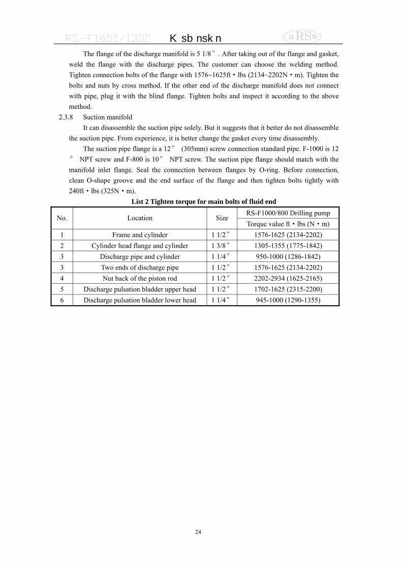
The flange of the discharge manifold is 5 1/8″. After taking out of the flange and gasket, weld the flange with the discharge pipes. The customer can choose the welding method. Tighten connection bolts of the flange with 1576~1625ft·lbs (2134~2202N·m). Tighten the bolts and nuts by cross method. If the other end of the discharge manifold does not connect with pipe, plug it with the blind flange. Tighten bolts and inspect it according to the above method.
2.3.8 Suction manifold It can disassemble the suction pipe solely. But it suggests that it better do not disassemble
the suction pipe. From experience, it is better change the gasket every time disassembly. The suction pipe flange is a 12″ (305mm) screw connection standard pipe. F-1000 is 12
″ NPT screw and F-800 is 10″ NPT screw. The suction pipe flange should match with the manifold inlet flange. Seal the connection between flanges by O-ring. Before connection, clean O-shape groove and the end surface of the flange and then tighten bolts tightly with 240ft·lbs (325N·m).
List 2 Tighten torque for main bolts of fluid end RS-F1000/800 Drilling pump
No. Location Size Torque value ft·lbs (N·m)
1 Frame and cylinder 1 1/2″ 1576-1625 (2134-2202) 2 Cylinder head flange and cylinder 1 3/8″ 1305-1355 (1775-1842) 3 Discharge pipe and cylinder 1 1/4″ 950-1000 (1286-1842) 3 Two ends of discharge pipe 1 1/2″ 1576-1625 (2134-2202) 4 Nut back of the piston rod 1 1/2″ 2202-2934 (1625-2165) 5 Discharge pulsation bladder upper head 1 1/2″ 1702-1625 (2315-2200) 6 Discharge pulsation bladder lower head 1 1/4″ 945-1000 (1290-1355)

M ud p um p
25
CHAPTER III PARTS LIST FOR RS-F1600/1300 MUD
PUMP
M ud p um p
26
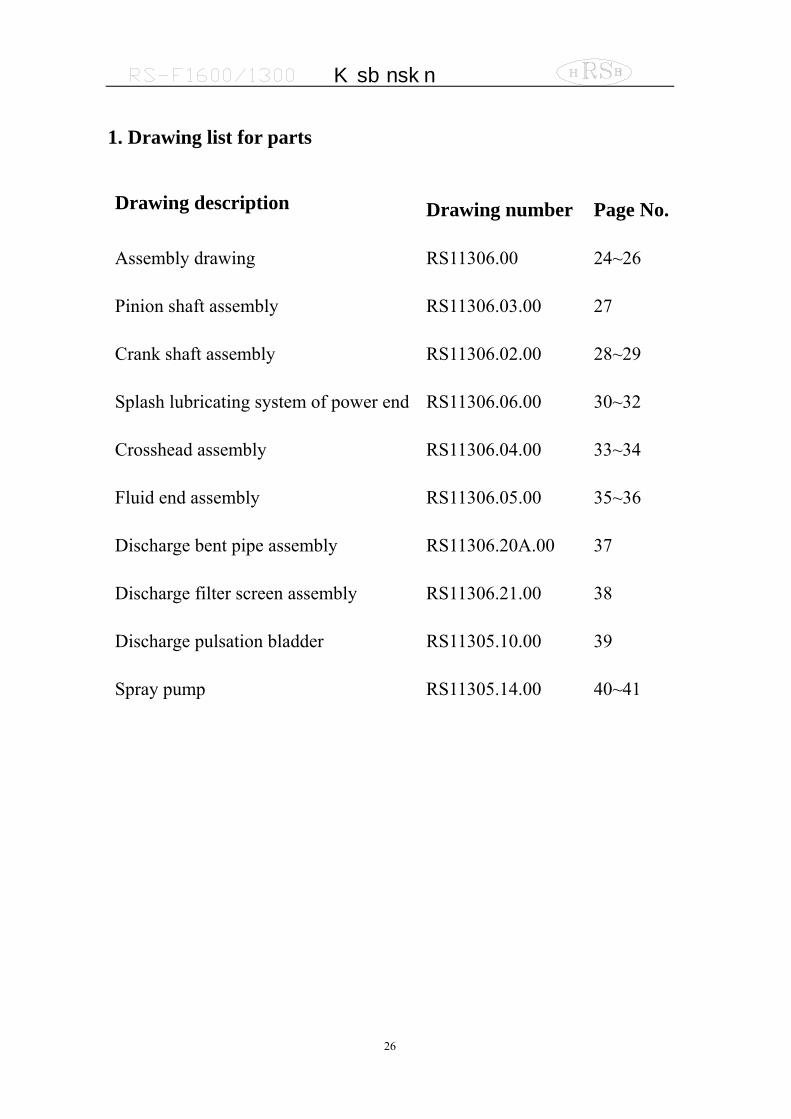
1. Drawing list for parts
Drawing description Drawing number Page No.
Assembly drawing RS11306.00 24~26
Pinion shaft assembly RS11306.03.00 27
Crank shaft assembly RS11306.02.00 28~29
Splash lubricating system of power end RS11306.06.00 30~32
Crosshead assembly RS11306.04.00 33~34
Fluid end assembly RS11306.05.00 35~36
Discharge bent pipe assembly RS11306.20A.00 37
Discharge filter screen assembly RS11306.21.00 38
Discharge pulsation bladder RS11305.10.00 39
Spray pump RS11305.14.00 40~41
M ud p um p
27
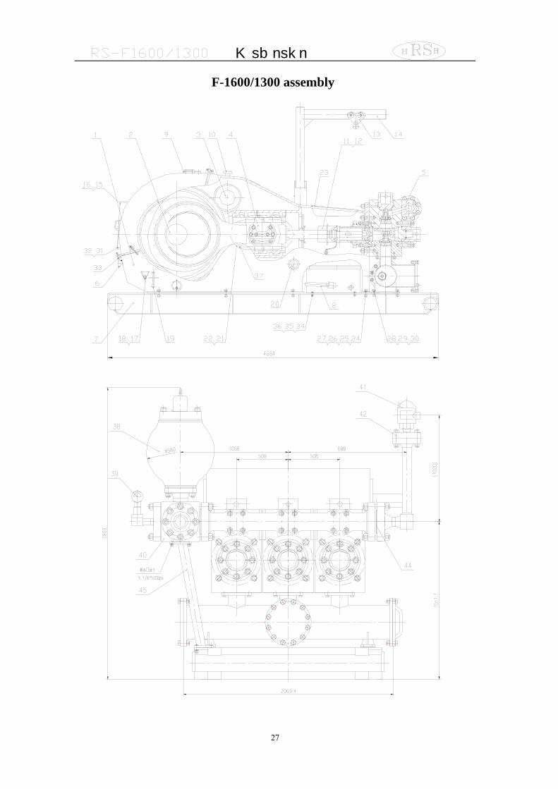
F-1600/1300 assembly

M ud p um p
28
Part list of F1600/1300 MUD Pump
M ud p um p
29
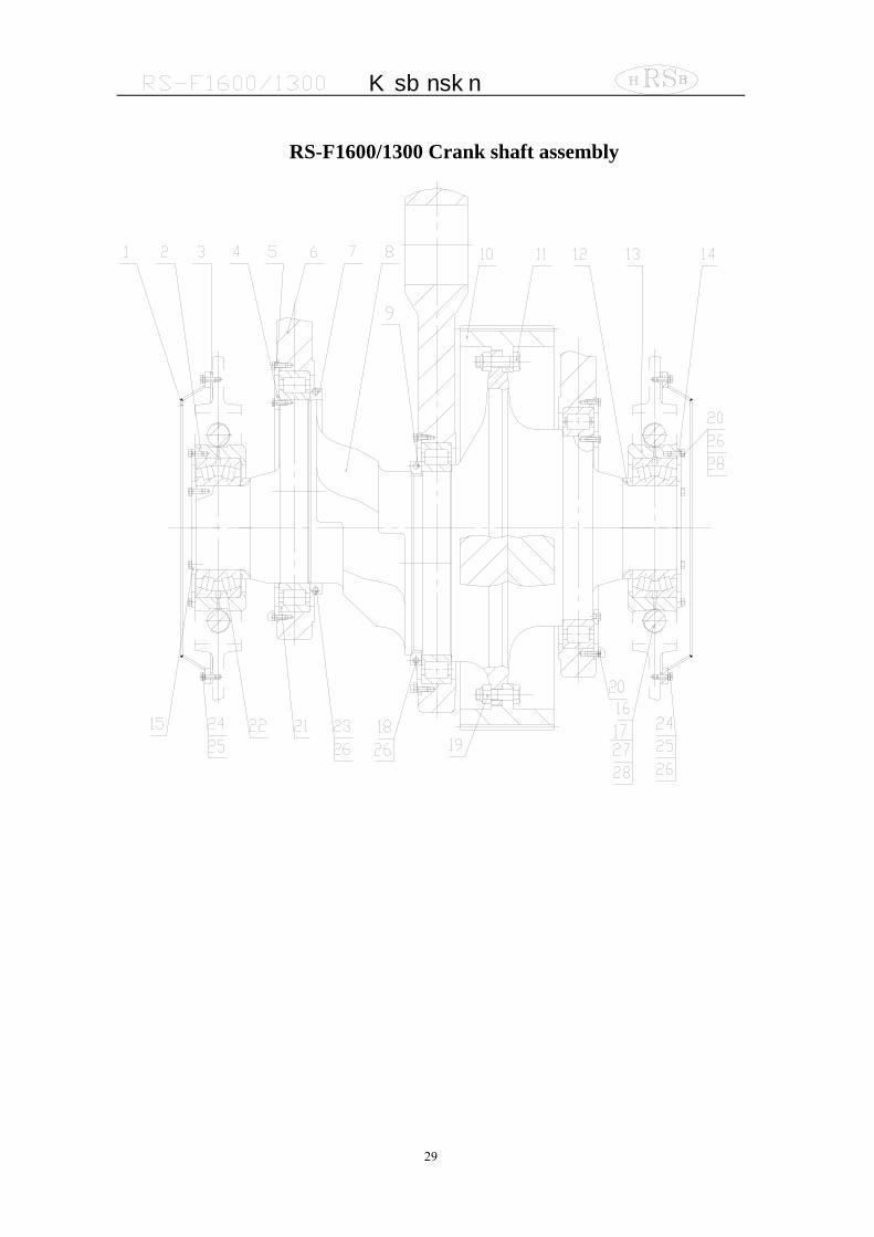
RS-F1600/1300 Crank shaft assembly
M ud p um p
30
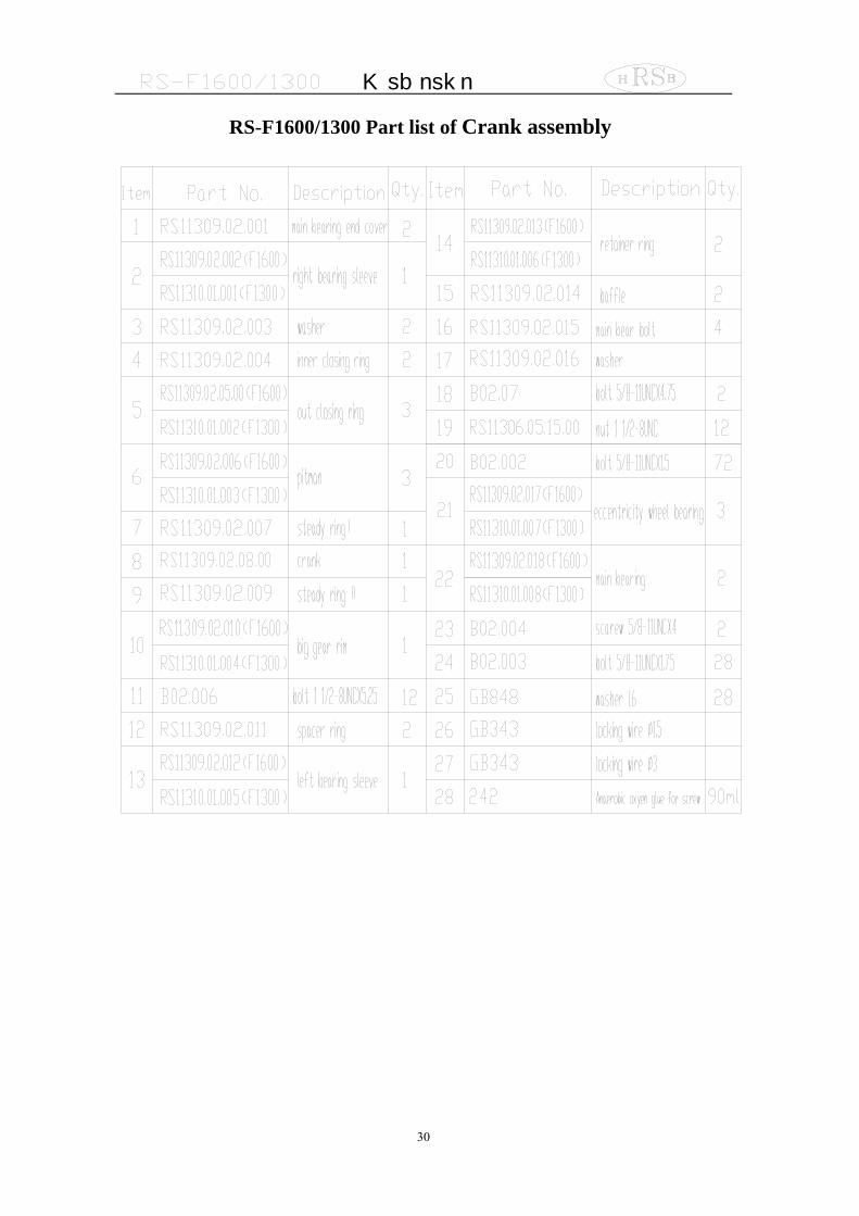
RS-F1600/1300 Part list of Crank assembly
M ud p um p
31
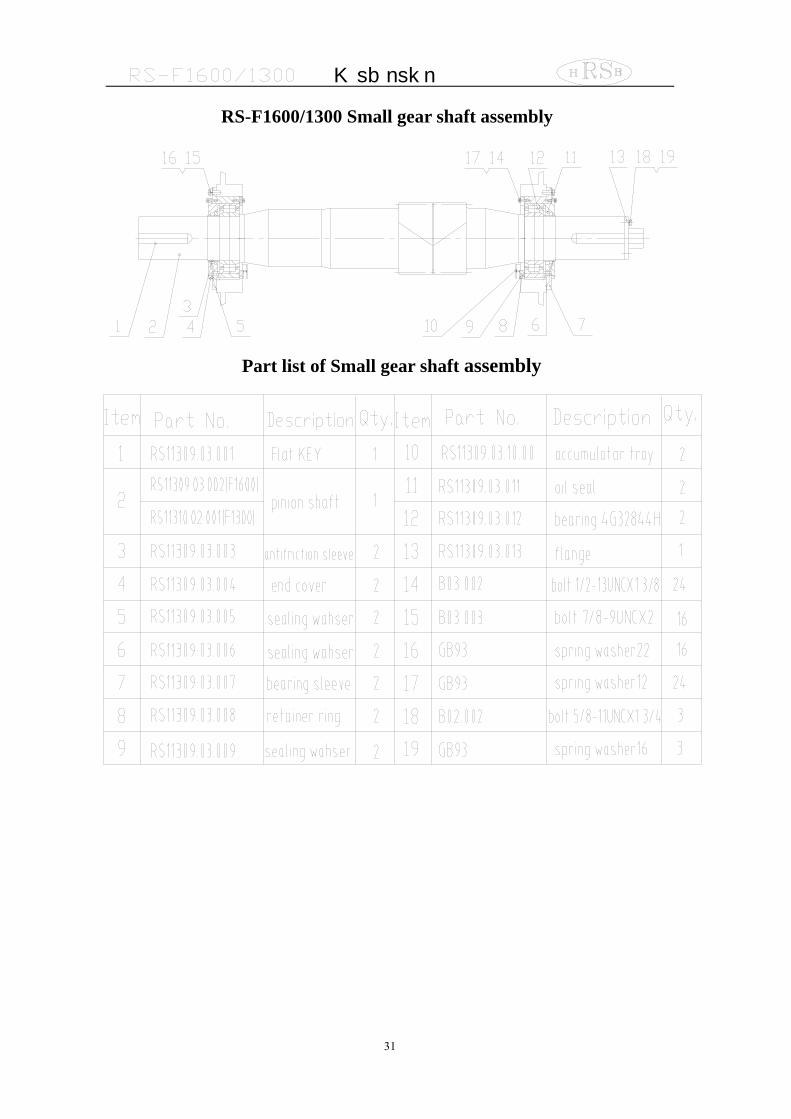
RS-F1600/1300 Small gear shaft assembly
Part list of Small gear shaft assembly
M ud p um p
32
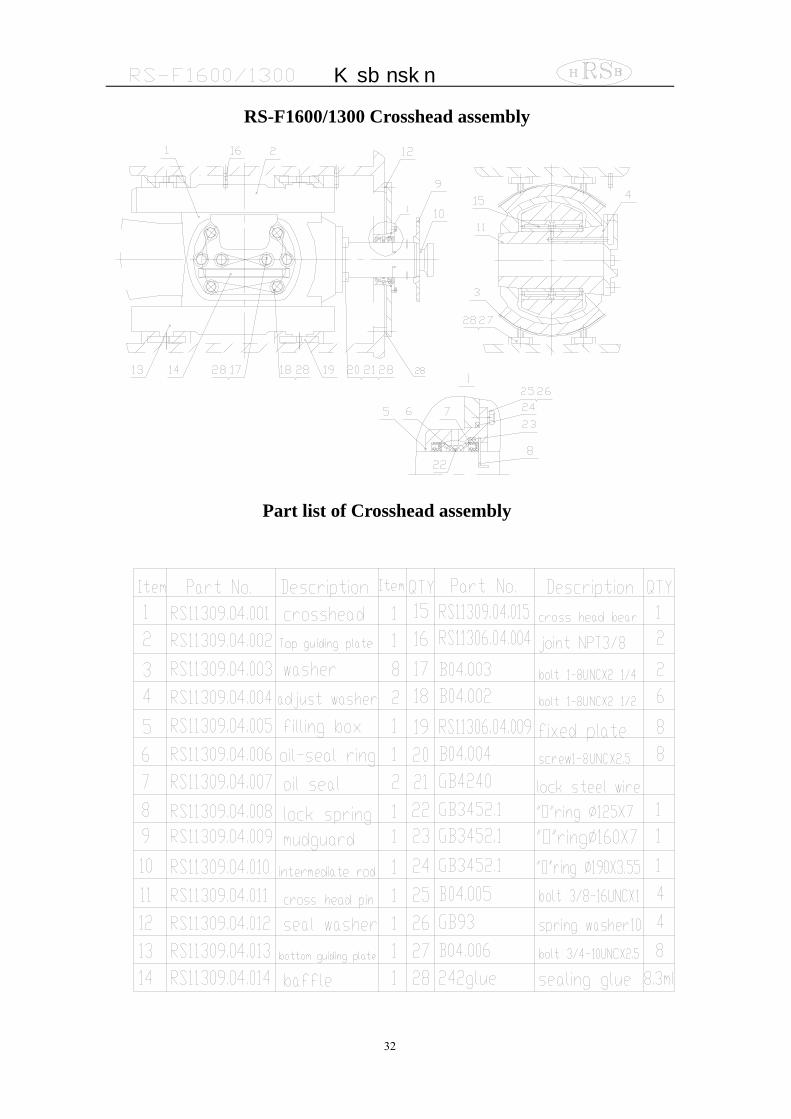
RS-F1600/1300 Crosshead assembly
Part list of Crosshead assembly

M ud p um p
33
RS-F1600/1300 Fluid end assembly

M ud p um p
34
Part list of Fluid end assembly

M ud p um p
35
RS-F1600/1300 Lubrication end assembly
M ud p um p
36
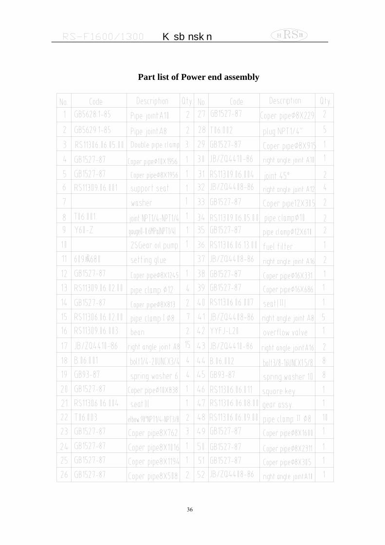
Part list of Power end assembly
M ud p um p
37
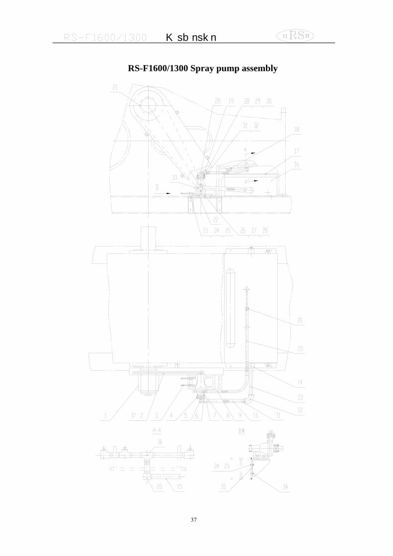
RS-F1600/1300 Spray pump assembly

M ud p um p
38
Part list of Spray pump assembly
M ud p um p
39
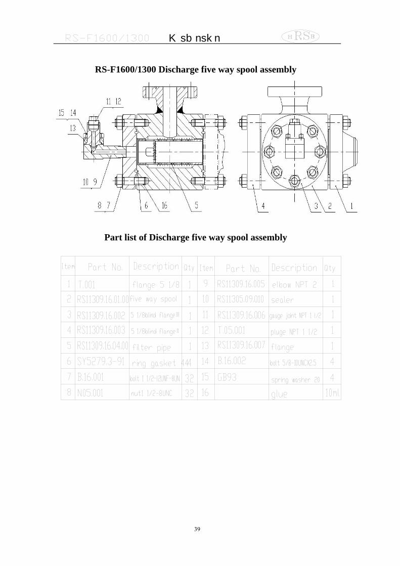
RS-F1600/1300 Discharge five way spool assembly
Part list of Discharge five way spool assembly
M ud p um p
40
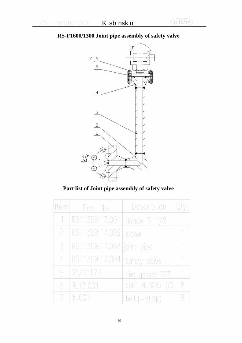
RS-F1600/1300 Joint pipe assembly of safety valve
Part list of Joint pipe assembly of safety valve
M ud p um p
41
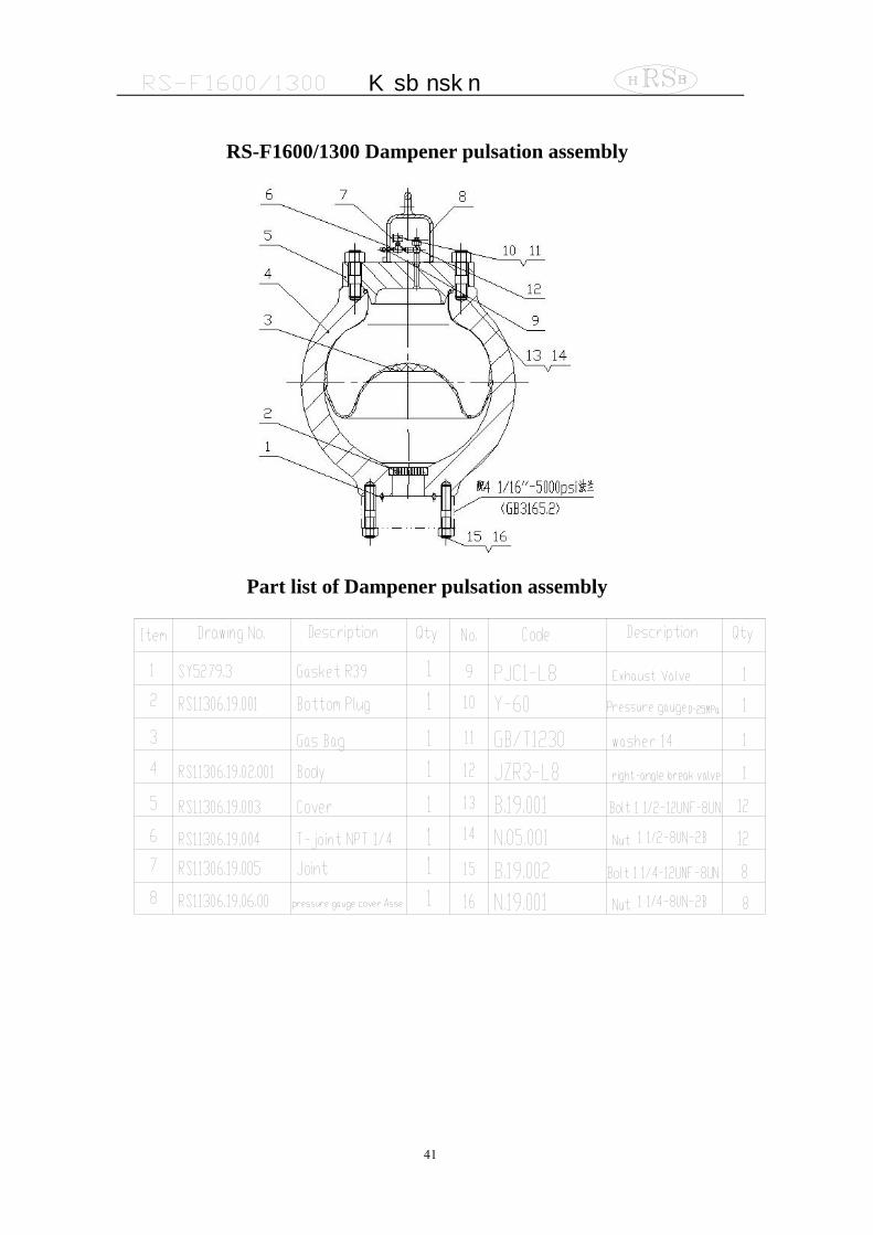
RS-F1600/1300 Dampener pulsation assembly
Part list of Dampener pulsation assembly
M ud p um p
42
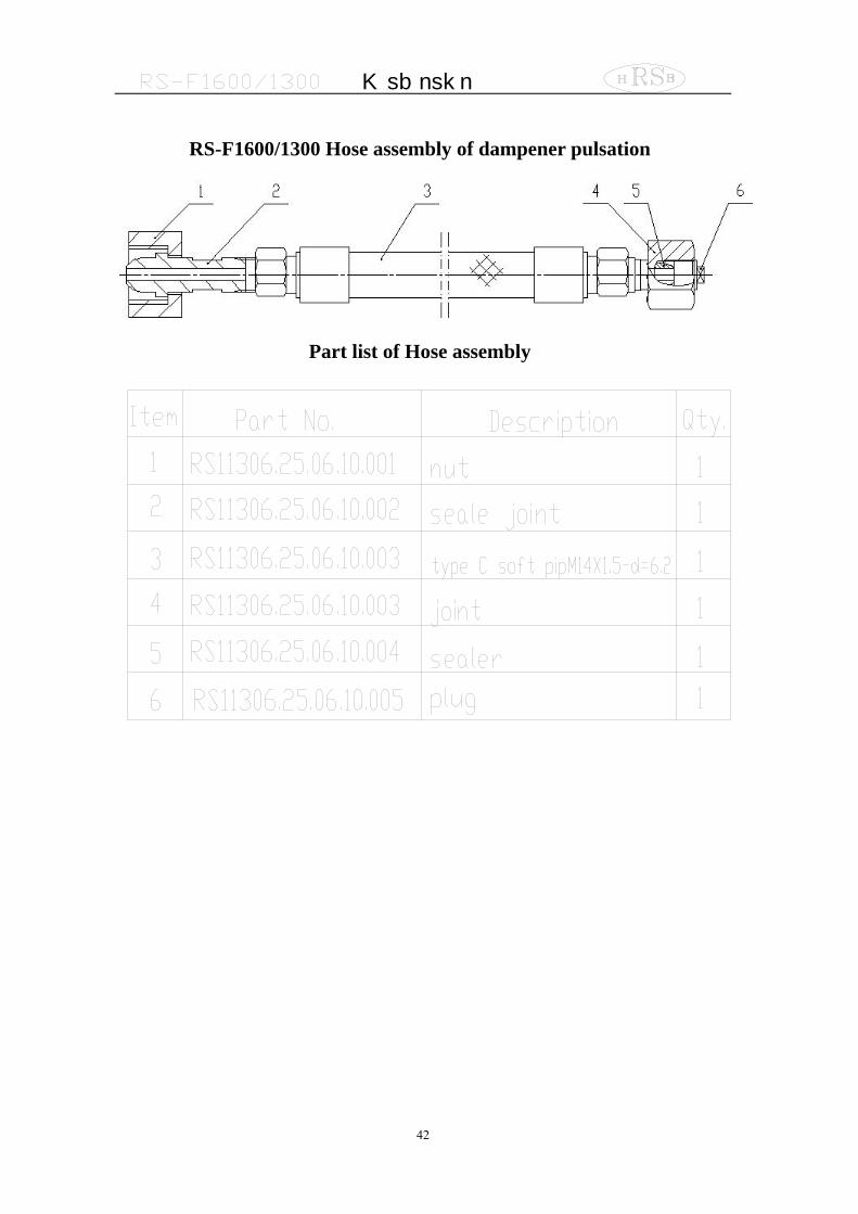
RS-F1600/1300 Hose assembly of dampener pulsation
Part list of Hose assembly