rs elektroniksysteme gmbh - thyristor controller esgt-3ph
TRANSCRIPT

RS Elektroniksysteme GmbH - Thyristor controller ESGT-3Ph, ESGT-3Ph/SP
1Version: 2021/10/04
ESGT-3PhESGT-3Ph/SP
L1 L2 L3
Elektroniksysteme GmbH
RSDevelopment and production of electronic systems
Eichelreuth 13 Phone: +49 8641 59 83 60D-83224 Grassau Fax: +49 8641 59 83 64
a
E-mail: [email protected] Internet: www.rs-steiner.com
Start-up instructions
Thyristor controllerType: ESGT-3Ph, ESGT-3Ph/SP
Three phase controller W3C
Contet
Page1. Important safety instructions................................................................................ 22. General instructions............................................................................................. 23. Technical explanations on thyristor controllers.................................................... 34. Installation of the thyristor controller ESGT-3Ph, ESGT-3Ph/SP......................... 45. EMC-equitable assembly..................................................................................... 46. Operation............................................................................................................. 67. Meaning of the clamp connections...................................................................... 78. Technical features of the control and monitoring panel....................................... 89. Basic circuit.......................................................................................................... 910. Control and monitoring print............................................................................... 1011. Analogue control................................................................................................ 1112. Survey of the individual types ............................................................................ 1313. Technical data.................................................................................................... 1414. Frame sizes........................................................................................................ 15

2
RS Elektroniksysteme GmbH - Thyristor controller ESGT-3Ph, ESGT-3Ph/SP
!!!
!
1. Important safety instructions
This manual contains instructions, which have to be observed for your personal safety and for the pre-vention of material damage. The instructions about your personal safety are highlighted with a warning triangle labelled with three exclamation marks, hints about material damages are listed with a warning triangle and one exclamation mark.
Danger-symbol Personal injury may occur, if appropriate safety precautions are not taken.
Caution-symbol Material damages may occur, if appropriate safety precautions are not taken into account.
Disposal regulations The devices contain electrical components and must not be disposed together with house- hold garbage. The devices for disposal have to be recycled according to local and currently valid regulations for electronic waste.
Qualified personnelThe corresponding device/system may only be set up and operated in conjuntion with this documenta-tion. Commissioning and operation of the device/system may only be performed by qualified person-nel. Qualified personnel within the meaning of the safety instructions in this documentation are per-sons with the authority to put electric circuits into operation, provide ground connections and label them according to current safety regulations.
The device should only be used in applications described in this document. The reliable and proper use of the product depends on appropriate transport, storage, installation and careful commissioning.
2. General instructions
Use of the documentThis instruction should demonstrate the technical application possibilities of the thyristor controller to the engineer in charge.
Target groupThe document should assist the user during commissioning. It also helps in case of service and main-tenance work. It supports the planner and project engineer with the conception of new plants.
Necessary competenceGeneric skills in the field of electrical engineering are necessary.
ValidityThe present document is valid for the thyristor controller of the type ESGT-3Ph... . It contains the currently valid description of the unit. We reserve the right to attach new descriptions of the devices. This involves types and options with modified version status of the technical documents.
Standards and approvalsThe thyristor controller of the type ESGT-3Ph... are based on the IEC/EN 60947-4-3 standard.

3
RS Elektroniksysteme GmbH - Thyristor controller ESGT-3Ph, ESGT-3Ph/SP
ESGT-3Ph/SP...
ESGT-1Ph/SP...
three phase current controller (mutlicycle control)
three phase current controller (based on the phase operating principle, phase angle control)
single phase regulator for AC current loads (based on the phase operating principle)
DisclaimerIt lies within the responsibility of the plant manufacturer of the technical equipment or machine to ensu-re the proper overall function. The producer can not guarantee all properties of the overall system or the machine.
3. Technical explanations on thyristor controllers
The thyristor controller is more and more used in sectors, in which bigger loads of ohm and inductive loads have to be regulated (i.e.: building of industrial furnaces, plastics processing, etc.).Due to its modular, compact construction and its controlling by a continual control signal, these wattage regulators become a perfect device for industrial control of wattage input. The power element of the thyristor controller consists of six antiparallel connected thyristors, the isolated cooling system and the electronic regulation and watching.
Type description:
Thyristor controllers for phase angle control (ESGT-3Ph… and ESGT-1Ph…) serve to control ohmic and inductiv loads. The activation is standardly made via proportional signals (0…10V, 0…20mA or 4...20mA). The phase angle or the on and off clock ratio with multicycle control is constantly adjusted by the control electronics, to achieve a sufficient proportionality between the activation and the output (T1, T2, T3) of the thyristor controller. Aside from the device series already mentioned, we have single and three phase versions, which cover the lower current range up to 12A. These devices are also available in snap-on design.
Current limiting:
At firing mode the current load can be regulated by a potentiometer between 1 and 100%. As a matter of fact the actual value of the current load is limited.
Voltage supply:
Different values of mains voltage are balanced so that any voltage variability of the load is avoided.
Construction:
The thyristor controller agrees with VDE 0558 part 1 and VDE 0160 table 4.
The thyristor controller ESGT-3Ph... is assembled modularly. It consists of three basic elements:
• power element with cooling system and thyristor switching facility • control unit with electronic starting and control system (diagnostic indicator, regulation port etc.)• function module which determines the analogous regulation

4
RS Elektroniksysteme GmbH - Thyristor controller ESGT-3Ph, ESGT-3Ph/SP
50-100mm
50-1
00m
m
H
T
B
!
!
4. Installation of the thyristor controller ESGT-3Ph, ESGT-3Ph/SP
The built-in device, according to IP 23 has to be mounted in a housing or a switchboard panel. Take care of adequate cooling (separate ventilation, for instance). The environment temperature must not exceed the value of 55°C. The device is to be mounted on a vertical plane, avoiding that the ventilating pipes of the cooling element are not placed vertical. The device has to be mounted in a dry room.
Further conditions to the operating area:
pŸrotection from dust and moisture pŸrotection from aggressive atmosphere fŸree from vibrations
No other devices should be placed closer than 50 to 100mm to the device, in order to provide adequate cooling.
The housing equipment according to IP 54 can be placed in locations Which are not protected from dust and moisture.
Wiring the device:
Build mains connection (L1, L2, L3) via fused circuit breakers with usual fuses.
The wiring for power supply and the wiring for control have to be laid in separate conduits or shield ducts.
It is essential to the electric installation to comply to the stipulations of the VDE (German Electrical Engineers Association), specifically to VDE 0100, VDE 0113, VDE 160.
5. EMC-equitable assembly
According to EMC standards thyristor controllers are regarded as components, which do not fulfil any intended use by themselves. The devices constitute a functional unit of the entire plant. The control electronics of the thyristor controllers are implemented according to valid EMC standards.The builder of the plant has to supply the plant with appropriate mains chokes and mains filters. These components can also be obtained from us. Thyristor controllers with multicycle control usually do not require any additional mains filter circuit.It should be noted that the standards of the resource category A are not sufficient in a special industrial sector, for example if sensitive measuring channels are affected. In this case, the user has to apply equipment of class B.The class A is the usual class of equipments, which is normally intended for the use in the industrial sec-tor. The devices are connected to the industrial network via an assigned transformer. Power controllers of class B are required if they should be used in the area of industry and small-scale industry and if they should be connected to the public low-voltage system.
Use of mains chokes:
On the input side of the thyristor controllers, mains chokes reduce the current-dependent line reactions and effect an improvement of the performance factor. This reduces the current harmonics and impro-ves the mains quality. The use of mains chokes is particularly recommended when connecting thyristor controllers with phase angle control to a grid-feeding point and when other electronic devices are attached to this network.

5
RS Elektroniksysteme GmbH - Thyristor controller ESGT-3Ph, ESGT-3Ph/SP
!!!
Use of mains filters:
Radio interference filters and mains filters (combination of radio interference filter and one mains choke) serve for protection against high-frequency disturbances, which are sent out via the power cable or the radiation of the power cable. The high-frequency disturbances should be limited to a mandatory or legal degree. Mains filters should possibly be mounted close to the thyristor controller and moreover it is necessary to ensure that the connecting cable between the thyristor controller and the mains filter is as short as possible.
CAUTION: The mounting surfaces of the thyristor controllers and the radio interference filters have to be free from paint and well conducting in the high-frequency range.
Furthermore, mains filters have leakage currents, which may become significantly larger than the nominal values in case of failure (phase failure, unbalanced load). To avoid dangerous voltages, the mains filters have to be grounded. As the leakage currents are high-frequent disturbances, the grounding measures have to be low-resistance and extensive.
With leakage currents, which exceed the value of 3,5mA, VDE 0160 or EN 60335 specify that either:
tŸhe cross section of the protective conductor has to be ≥ 10mm², tŸhe protective conductor has to be monitored on interruption or aŸ second protective conductor has to be laid.
Shielding measures:
Shielding measures help to reduce the radiated interference energy. Electrical lines between thyristor controller and load can be laid shielded. Thereby the shield must not replace the PE line. Four-wire cables (three phases + PE), whose shield is double-sided and extensive laid on earth potential (PES), are recommended. The shield must not be applied over the connecting wires. Interruptions of the shielding e.g. in the case of clamps, contactors, mains chokes etc. have to be bridged with low-resis-tance and appropriate space considerations. In practice this can be done for example by interrupting the shield close to the assembly and then connecting it extensively with the earth potential (PES, shield clamp). The free cables, which are not shielded, should not be longer than 100mm.
Grounding measures:
Grounding measures are absolutely necessary to fulfil legal provisions. They constitute a prerequisite for an efficient use of further measures such as filters and shielding. All conductive, metallic housing components have to be electroconductive connected with the earth potential. For the EMC-measure, the important factor is not the cable´s crosssection, but its surface, since this is where high frequency current flows to earth. Once again, all grounding points have to be led directly, extensively and with low-resistance to the central grounding point (equipotential bonding bar, star-shaped grounding system). The contact points have to be free from paint and corrosion (use galvanized mounting plate and materials).

6. Operation
To begin with, the electrical connections are to be done, according to the accompanying plans: L1, L2, L3 (rotating field right), T1(U), T2(V), T3(W).
The thyristor controller have to be connected to the power supply according to the VDE rules, in a way that they can be disconnected again by appropriate switching means (i.e. master switch, contactor, protective power switch).
Conducting wire installation:
The power supply, the user supply, as well as the control wiring have to be placed in separate ducts or conduits.
To avoid malfunction, it is advisable, to install the electronic signal wiring separated from the power supply and/or from the protective control wiring as well as to twist the feed and return signal lines or use shielded control lines (see also point 5. EMC-equitable assembly).
Fuses:
The mains fuse protection depends on the recommended or employed power-transmission crosssec-tion and has to be carried out, according to DIN 57100, part 430/VDE 0100 and part 430/6.81.
The options /ES (electronic switch-off), /IB (electronic current limitation), /IS (symmetric current monitoring) and /IU (low current recognition) provide a malfunction report output with a simultaneous LED display.
The control electronics synchronously turn off the current of the power element.
General information on the PTC-thermistor:
Technical data PTC
6
RS Elektroniksysteme GmbH - Thyristor controller ESGT-3Ph, ESGT-3Ph/SP
!
Cold resistance at a cold-conductor temperature of J -5KNAT
Cold resistance at a cold-conductor temperature of J +5KNAT
Cold resistance at a cold-conductor temperature of J +15KNAT
Reproducibility of JNAT
Cold resistance R25
Thermal response time ta
± 5
Single
± 5
Triplet
K± 0,5 ± 0,5 K
³ 1330 ³ 3990 W
³ 4000 ³ 12000 W
£ 100 £ 300 W
£ 550 £ 1650 W
£ 5 £ 5 s
PTC-temperature sensors according to DIN 44081 (tripelt design DIN 44082) are used to protect electrical machines against thermal overload. According the presend DIN standard the are arbitrarily exchangeable among them-selves. It is a range of types from 60 to 190°C available. PTC-temperature sensors with different rated shut-off temperatures can also be connected in series. Thereby it is possible to get optimum use out of machine. Components and winding parts with different limit temperatures and to protect them cost-effectively.

7. Meaning of the clamp connections
Clamp connections on the function panel:
These connections can be found on the function module and obey the following numbering scheme.
Clamps on the control and monitoring print:
7
RS Elektroniksysteme GmbH - Thyristor controller ESGT-3Ph, ESGT-3Ph/SP
1, 2
3, 4
5, 6
activated: closed
in operation: closed
Activation:
Special functions:
standby: open
blocking the power element: open (The red LED will be illuminated if clamps 5 - 6 are open)
Connection of 230V AC(Option: Any control voltages can be realised at customer wish )
output switch terminal S1Contact positions see time diagram on the page 8
output switch terminal S2Contact positions see time diagram on the page 8
voltage supply for potentiometer control (can be found on the analogous module)
malfunction report output switch terminalContact positions:• without auxiliary voltage in normal operation: 21 - 22 closed• with auxiliary voltage in norma operation: 21 - 22 closed• without auxiliary voltage at the fault: 21 - 22 closed• with auxiliary voltage at the fault: 21 - 20 closed
5, 6
L1, N
14, 15, 16
17, 18, 19
7
23, 24
20, 21, 22
auxiliary input, i.e. for PTC-sensor according to DIN 44081 or other applications• 23 - 24 open = lock• 23 - 24 closed = in operation

8
RS Elektroniksysteme GmbH - Thyristor controller ESGT-3Ph, ESGT-3Ph/SP
Meaning: Auxiliary voltage connected (device in operation)
Activation
switching facility S2 actuated
Reason: Overstressing of the motor (see motor data)
Meaning: Phase failure
Reason: Overload, to high current, to high switching frequency. The threshold value of turning off is at 75° C.
Reason: One or more phases are not connected with the mains connections L1, L2, L3 (Check the contacts!)
switching facility S1 actuated (contacts S1 and LED S1 are activated synchronously)
LED 1 (rd)
LED 2 (rd)
LED 3 (rd)
LED 4 (gn)
LED “SE”
LED “S2”
LED “S1”
t
t
t
UMot
S1
S2
t
SE
Start
100%
OFF
U = 0%S
15
1818 18
15 1516
14
19
17
19
17
19
17
16
14
16
14
8. Technical features of the control and monitoring panel
The control panel of the thyristor controller provides various control and protection functions. This panel is supplied with 230V AC by the clamps L1 and N in the normal equipment. The control panel also consists of an interchangeable function panel (100x75mm) which determines the function mode of the device.
Explaination of the LEDs on the control and function panel
If there is none of the explained malfunctions, all red LEDs have to go out by activating the device (e.g. by connecting the contacts 1 - 2 / reset procedure).
The switch positions show the clamp contacts from 14 to 19 at the control panel.

9. Basic circuit
Follow the clockwise phase shift!
Note: The option constant current controlling (/I) or current limitation (/IB) is sensibly applicable only for devices with firing mode, because here a continuous measurement of the load current makes sense.
* For isolate you can plug connection, fuses, circuit-breakers, load-breakers and residual current devices (RCDs). Contactor, however, can be used only in exceptional cases and due to isolate.
9
RS Elektroniksysteme GmbH - Thyristor controller ESGT-3Ph, ESGT-3Ph/SP
L1L2L3N
F1 F2
Load
Current-watching
Option:
*
or:
L1 N L2 L3L1Thyristor controller: ESGT-3Ph...Mode:Threee-phase a.c. controller as
orphase angle controlmutlicycle control
T1 T2 T3
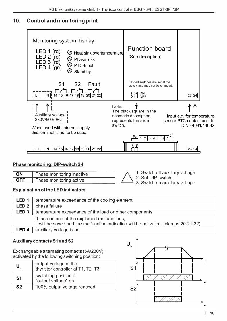
10. Control and monitoring print
Phase monitoring: DIP-switch S4
Explaination of the LED indicators
Auxiliary contacts S1 and S2
Exchangeable alternating contacts (5A/230V), activated by the following switching position:
10
RS Elektroniksysteme GmbH - Thyristor controller ESGT-3Ph, ESGT-3Ph/SP
Function board(See discription)
Monitoring system display:
LED 1 (rd) LED 2 (rd) LED 3 (rd) LED 4 (gn)
S1 S2 Fault
Heat sink overtemperature
Phase loss
PTC-Input
Stand by
Input e.g. for temperature sensor PTC-contact acc. to
DIN 44081/44082When used with internal supply this terminal is not to be used.
Auxiliary voltage230V/50-60Hz
temperature exceedance of the cooling element
auxiliary voltage is on
100% output voltage reached
phase failure
temperature exceedance of the load or other components
LED 1
LED 4
S2
LED 2
LED 3
If there is one of the explained malfunctions, it will be saved and the malfunction indication will be activated. (clamps 20-21-22)
t
t
t
UL
S1
S2
UL
S1
output voltage of the thyristor controller at T1, T2, T3
switching position at “output voltage" on
23 24ONOFFL1 N 14 15 16 17 18 19 20 21 22
Dashed switches are set at the factory and may not be changed.
Note:The black square in the schmatic description represents the slide switch.
S4S3
1 2 3 4 5 6 7S1
Ps
23 24L1 N 14 15 16 17 18 19 20 21 22
Phase monitoring activeOFF
Phase monitoring inactiveON!
1. Switch off auxiliary voltage2. Set DIP-switch3. Switch on auxiliary voltage

RS Elektroniksysteme GmbH - Thyristor controller ESGT-3Ph, ESGT-3Ph/SP
11
11. Analogue control
1 2 3 4 5 6 7
Potentiometer control:1kW - 10kW
Softstart / tan
0s 10s
SwitchS1
LED1: Level
LED2: SP
LED3: Fault
LED4: SE
LED5: S1
LED6: S2
J4 : 4...20mA
GN
D
Ure
f: +
10V
Sta
rt / A
ctiv
atio
n
Ust
/ Is
t
ON
OFF
Function board (Analogue control)
13
12
11
10
9
8
16
15
14
LEDs Function
LED1: Level Intensitiy is proportional to the level control
LED2: SP
Device errorLED3: FaultON: faultOFF: ready
flashes at the same rateas the multicycles
LED is only active atphase angle control (Ph)
LED is only active atmulticycle control (SP)
LED4: SEON: clamp 1, 2 closed
OFF: clamp 1, 2 opened
S1LED5: S1ON: load voltage > 0%OFF: load voltage = 0%
S2LED6: S2ON: load voltage = 100%OFF: load voltage < 100%
Switching status
n.c.
n.c.
n.c.
J3: Ph / SP(factory setting)
J1: n.c.
J2: not working
11.1 LEDs
Sw
itch o
ff a
t danger
with
reta
inin
g funct
ion
16
15
14
n.c.
n.c.
n.c.
n.c.
n.c.
n.c.
Analoguemodule 2
ON
OFF
Note:The black square on the switch picture shows the slide control.

RS Elektroniksysteme GmbH - Thyristor controller ESGT-3Ph, ESGT-3Ph/SP
12
11.2 Clamps
Clamps Function Setting
1, 2opened: standby
closed: activated
Reset1, 2opening and closingresets the device
Ust: Control voltage,Ist: Control current
30...10V (S1: OFF, J4: opened)0...20mA (S2: ON, J4: opened)4...20mA (S2: ON, J4: closed)
Switch off at dangerwith retaining function
5, 6opened: fault
closed: ready
Uref: +10VReference voltage forpotentiometer control
7
GNDGround for control signals
4
8, 910, 11
12, 13
n.c.14, 15, 16
Control signal Switch S1 Jumper J4
Ust: 0...10V OFF opened
Ist: 0...20mA opened
Ist: 4...20mA closed
ON
ON
Jumper J3
Phase angle control (Ph) opened
Multicycle control (SP) closed
Kind of control mode
Jumper J2
Non-feedback control mode opened
Feedback control mode(Constant voltage regulation)
not working
Control mode
11. 6 Control signals
11. 4 Control modes
11. 5 Kinds of control mode for devices with Phase angle control (Ph) or Multicycle control (SP)
Potentiometer Function SettingSoftstart / tan Ramp-up time adjustable 0...10s
11. 3 Potentiometer
Output: +10VDC / max. 10mA
n.c.n.c.
n.c. n.c.
n.c.
n.c.
n.c.
(factory setting)

13
RS Elektroniksysteme GmbH - Thyristor controller ESGT-3Ph, ESGT-3Ph/SP
A
F
C
C
E
B
F
D
B
F
D
B
E
A
F
C
B
D
B
F
D
C
E
1,3
79,0
9,5
7,5
32,0
2,3
93,0
18,0
1,9
90,0
15,0
2,4
28,0
1,3
82,0
10,5
2,3
22,0
1,9
90,0
15,0
7,0
30,0
13
3375
324
243
2700
94
5790
945
40
4710
594
162
1512
22
4320
432
135
1134
67
5010
756
202
1944
3
860
78
60
690
23
1730
240
10
1300
145
41
380
5
1100
100
33
290
16
1450
193
50
490
1,5
630
35
25
500
6,0
2x630
120
2,5
2x500
70
16
240
1,5
2x400
50
10
150
4,0
2x500
95
16
300
16
1250
125
100
1000
35
2500
355
25
2000
250
80
630
16
1600
160
50
400
25
2000
315
80
800
10
1800
130
100
1200
40
2800
450
25
2500
300
80
750
15
2000
200
60
600
30
2500
400
80
900
5
1250
120
90
1000
35
2500
350
15
1850
220
60
560
8
1600
160
50
420
25
2100
280
75
720
200x140x115
850x750x470
360x252x200
360x252x200
600x540x346
260x205x170
850x750x470
415x525x210
260x205x170
850x750x470
360x445x210
260x205x170
600x540x346
200x140x115
850x750x470
360x252x200
260x205x170
415x525x210
260x205x170
850x750x470
415x525x210
360x252x200
600x540x346
H
T
B
[kg][W][kW][mm²][A][A][A] [mm]m
ax. lo
ad
cu
rren
t
rec. sem
i-co
nd
ucto
r fu
ses
rec. cro
ss-
secti
on
max. p
ow
er*
*
Po
wer
loss
at
no
min
al
rati
ng
Fra
me s
ize
Weig
ht
Dim
en
sio
ns
WxH
xD
Main
s f
use
12. Survey of the individual types
Errors and technical modifications excepted (Date: 2015/12)
Recommendations of the cross sections according to VDE 0298-4 (August 2003), table 4, laying system E and F
* The given details also apply to the version with multicycle control ESGT-3Ph/SP... ** The given values for the max. power applies to operation at 3x 400V. The circuit can be in star connection or delta connection. To take account of this, the resistance values of the load. (Example: Power resistors for 230V AC can't be connected in delta connection)
The given values refer to the operation voltage of 3x400V AC. The values given for overload refer to a surrounding temperature exceed of max. 55°C and an installa-tion altitude of 1000m. (VDE 0298 part 4, August 2003).

13. Technical data
Errors and technical modifications excepted (Date: 2016/11)
Options• constant current controlling (/I) • low current recognition (/IU)• constant voltage controlling (/U) • load limiting: U x I – Regulationg (/UxI)• current limitation (/IB) • power controlling: P = f(U, I) (/P)• current output 0...10V (/AI) • voltage feedback: U² (/U²)• voltage output 0...10V (/AU) • current feedback: I² (/I²)• modified auxiliary voltage 24V DC (/24VDC) • power controlling: P = f(1/RL) (/RL)• modified auxiliary voltage 400V AC (/400V) • interface: Profibus (/Prof)• internal auxiliary voltage (/IV) • interface: Modbus (/Mod)• mains voltage: 3x 110V AC (/110V) • interface: Canbus (/Can)• mains voltage: 3x 500V AC (/500V) • interface: RS 232 (/RS-232) • mains voltage: 3x 690V AC (/690V) • interface: RS 485 (/RS-485) • mains voltage: 3x 1000V AC (/1000V) • kind of protection: IP 55 (/IP55) • electronic switch-off (/ES) • kind of protection: IP 65 (/IP65) • symmetric current monitoring (/IS) • power saver circuit (/Spsch)
self synchronizing
VDE 0160 5.5.1.3 / DIN EN 50178
ohmic and induktive load
vertical, electrical connections downside
cf. table "12. Survey of the individual types" (5 – 2500A)
IP 23
LEDs (SE, S1, S2)
48Hz...62Hz
E according to DIN 40040
0...+55°C
5...100% of the In
phase failure, temperature exceedance of the cooling element, lack of voltage
230V AC / 50-60Hz standard(optional: 24V DC, 400V AC internal)
3x 400V AC ± 15% (optional: 3x 110V, 3x 500V, 3x 690V, 3x 1000V)
EMC Directive 2014/30/EULVD 2014/35/EURoHS Directive 2011/65/EU
Phase sequence
Built in device
Types of the load
Installation
Max. current load
Kind of protection
Indication of operation mode
Mains frequency
Moisture class
Ambient temperature
Current limiting
Malfunction indication
CE-regulations
Power supply
Mains voltage
Control signals(standard)
optional
RS Elektroniksysteme GmbH - Thyristor controller ESGT-3Ph, ESGT-3Ph/SP
14
• 0...5V DC• 0...10mA DC• 0...5mA DC• 10...0V DC (inverse)• 20...4mA (inverse)• 20...0mA (inverse)
• 0...10V DC• 0...20mA DC • 4...20mA DC• potentiometer input (5kΩ...25kΩ): 0...10V DC

RS Elektroniksysteme GmbH - Thyristor controller ESGT-3Ph, ESGT-3Ph/SP
15
function board
Connection:control electronic
160
200
12
5
14
0
control board
function board
115
protection cover (can be taken off)
power connections
L1
L2
L3
T1
T3
PE
T2
mounting holes Ø = 8mm
date name
RS
Elektroniksysteme GmbH
Eichelreuth 13D-83224 Grassau
Tel.: 08641/598360Fax.: 08641/598364
Thyristor controllerESGT-3Ph...frame size A
14. Frame sizes
Frame size: A
Power connections (L1...T3): according to version(ESGT-3Ph 05, 08, frame size A)
Due to ongoing technical development and modifications we reserve the right to deliver products which might be slightly different from those described above.

Frame size: B
Power connections (L1...T3): 1,5 to 6mm²(ESGT-3Ph 15, 25, 35, 50, 60, frame size B)
Due to ongoing technical development and modifications we reserve the right to deliver products which might be slightly different from those described above.
RS Elektroniksysteme GmbH - Thyristor controller ESGT-3Ph, ESGT-3Ph/SP
16
function board
Connection:control electronic
fan fan
230
260
120
170
205
control board
function board
170
mounting holes Ø = 8mm
date name
RS
Elektroniksysteme GmbH
Eichelreuth 13D-83224 Grassau
Tel.: 08641/598360Fax.: 08641/598364
Thyristor controllerESGT-3Ph...frame size B

Frame size: C
Power connections (L1...T3): M8(ESGT-3Ph 75, 90, 120, 160, frame size C)
Due to ongoing technical development and modifications we reserve the right to deliver products which might be slightly different from those described above.
RS Elektroniksysteme GmbH - Thyristor controller ESGT-3Ph, ESGT-3Ph/SP
17
control board
Function board
185
200
mounting holes Ø = 8mm
function board
Connection:control electronic
L1 T1 L2 T2 L3 T3
fan fan
140
213
252
330
360
protection cover (can be taken off)
date name
RS
Elektroniksysteme GmbH
Eichelreuth 13D-83224 Grassau
Tel.: 08641/598360Fax.: 08641/598364
Thyristor controllerESGT-3Ph...frame size C

Frame size: D
Power connections (L1...T3): M8(ESGT-3Ph 220, 280, 350, 420, frame size D)
Due to ongoing technical development and modifications we reserve the right to deliver products which might be slightly different from those described above.
RS Elektroniksysteme GmbH - Thyristor controller ESGT-3Ph, ESGT-3Ph/SP
18
function board
Connection:control electronic
L1 T1 L2 T2 L3 T3
420
445
340
T1 T2 T3L1 L2 L3
function boardcontrol board
mounting holes Ø = 8mm
21
0
fanfan
auxiliary fan: ESGT-3Ph 280, 350, 420 80
330
360 55
date name
RS
Elektroniksysteme GmbH
Eichelreuth 13D-83224 Grassau
Tel.: 08641/598360Fax.: 08641/598364
Thyristor controllerESGT-3Ph...frame size D

Frame size: E
Power connections (L1...T3): M10 / M8(ESGT-3Ph 560, 720, 1000, frame size E)
Due to ongoing technical development and modifications we reserve the right to deliver products which might be slightly different from those described above.
RS Elektroniksysteme GmbH - Thyristor controller ESGT-3Ph, ESGT-3Ph/SP
19
function board
Connection:control electronic
40
0
28
0
fan fanfan
28
0
34
6
function board
L3L2L1
T2T1 T3
30
54
0
L1 L3L2
mounting holes Ø = 9mm
510
600
560
protection cover (can be taken off)
date name
RS
Elektroniksysteme GmbH
Eichelreuth 13D-83224 Grassau
Tel.: 08641/598360Fax.: 08641/598364
Thyristor controllerESGT-3Ph...frame size E

RS
Ele
ktroniksyste
me G
mbH
- Thyristo
r contro
ller E
SG
T-3
Ph, E
SG
T-3
Ph/S
P
20
Frame size: F
Power connections (L1...T3): M12(ESGT-3Ph 1250, 1600, 1850, 2100, 2500, frame size F)
Due to ongoing technical development and modifications we reserve the right to deliver products which might be slightly different from those described above.
85
85
30
fan
L2
fanfan
function board
Connection:control electronic
L1
L3
T3T2
mounting holes Ø = 12mm
L2
function board
L1
T1
L3
850
800
760
ca.170
ca.300
530
750
470
390
date name
RS
Elektroniksysteme GmbH
Eichelreuth 13D-83224 Grassau
Tel.: 08641/598360Fax.: 08641/598364
Thyristor controllerESGT-3Ph...frame size F