rr piling manual - bredenberg teknik · rr piling manual 3 1. general this manual deals with...
TRANSCRIPT
RR Piling Manual
2
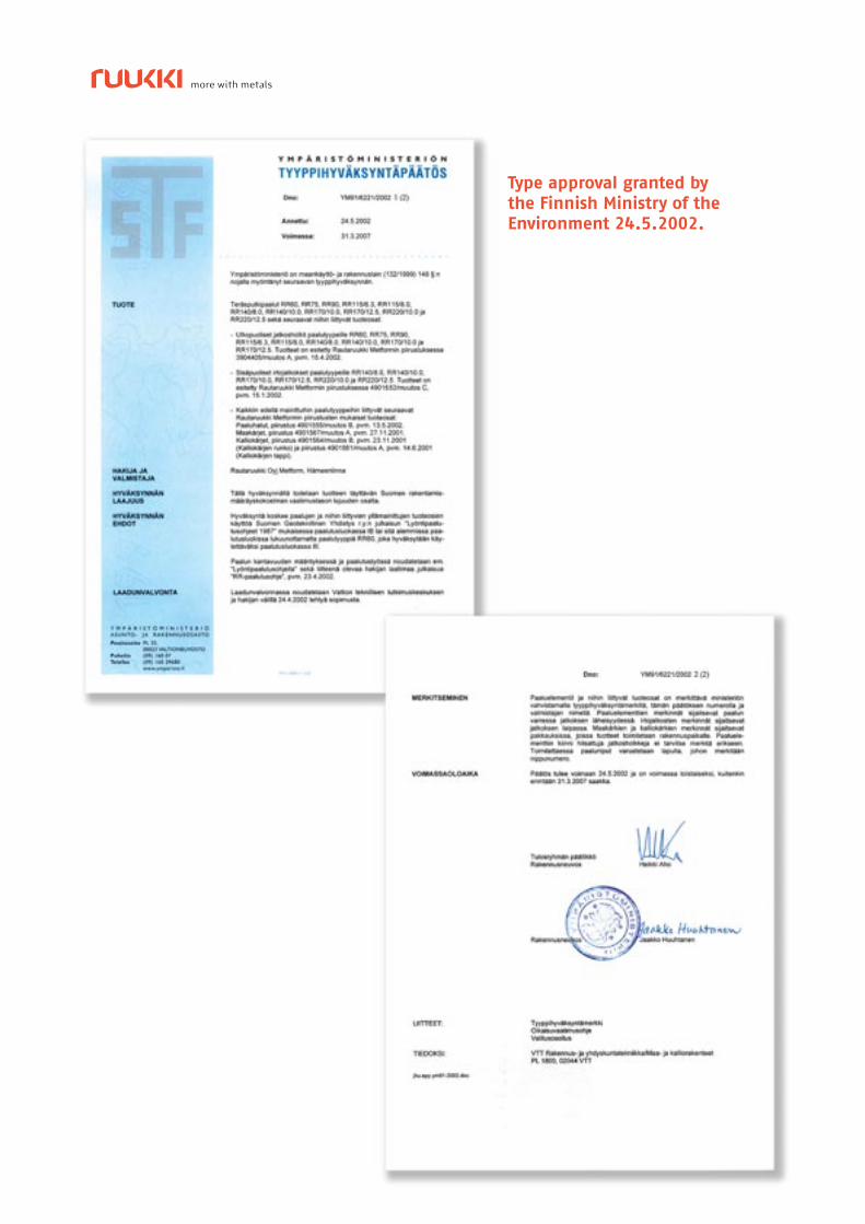
Type approval granted by
the Finnish Ministry of the
Environment 24.5.2002.
RR Piling Manual
3
1. General
This manual deals with impact-driven RR piles. It is an
abridgement of the RR Piling Handbook which contains
more detailed instructions on the design, installation
and supervision related to RR piling.
2. Requirements of RR piling site
Piling class III (Easy projects)
• Lightweight and basic buildings and constructions
not intended for permanent habitation.
• Sites with easy soil conditions.
Piling class II (Demanding projects)
• Lightweight and basic residential buildings and
constructions.
• Sites with easy soil conditions.
Piling class IB (Very demanding projects)
• Bridges, hydraulic structures, industrial structures
and other corresponding engineering structures.
• Large or complicated structures and buildings
located in areas of organic or fi ne-grained soils.
• Sites where rock is overlaid only by organic or
fi ne-grained soils.
• Structures subject to dynamic or otherwise excep-
tional loads such as signifi cant horizontal loads,
bending or heavy vertical loads, or special require-
ments.
• Structures incorporating piles driven through thick
fi ll.
3. Soil investigations
The following case-specific site investigations are
recommended.
Piling class III (Easy sites)
Piles bearing on ground
• Weight sounding at least at each corner of building
or structure to be founded.
• In exceptional cases RR piling may be considered
to substitute for sounding. Then, pile-driving resis-
tance must be documented as dynamic-probing
resistance. Pile bearing capacity must be deter-
mined based on end-of-driving criteria.
Horizontally loaded piles
• Weight sounding at least at each individual founda-
tion or at every fourth noise-barrier or fence pier or
no more than 20 metres apart.
Piling class II (Demanding sites)
Piles bearing on ground or rock
• Dynamic probing may be substituted by weight
sounding if it can be assured that the piles reach a
compact coarse-grained soil or moraine layer.
• Dynamic probing must be performed at least at
each corner of the building to be founded and at 5-15
metre intervals depending on the degree of varia-
tion in soil conditions. Probing must go as deep as
possible since RR piles often penetrate deeper than
dynamic probing.
• The defi nition of the parameters needed in calcula-
ting the buckling load of a pile requires performing
vane tests.
• Disturbed samples should be taken from every
fourth test hole in order to determine soil-layer
boundaries.
Horizontally loaded piles
• Weight sounding or cone penetration tests at each
individual foundation or at every fourth noise barrier
or fence pier or no more than 20 metres apart.
• Disturbed samples should be taken from every
fourth test hole in order to determine soil-layer
boundaries.
• Vane tests at each fourth individual foundation or at
every fourth noise barrier or fence pier or no more
than 20 metres apart.
Piling class IB (Very demanding sites)
General
At very demanding sites an investigation is required
at each foundation and at each corner of large founda-
tions such as pile-group foundations of bridges.
Piles bearing on ground
• Dynamic probing must penetrate as deep as possible.
4
• Disturbed samples should be taken from every
fourth test hole in order to determine soil-layer
boundaries.
• The defi nition of the parameters needed in calcula-
ting the buckling load of a pile requires performing
vane tests.
• In the case of fi ne-grained and organic soil layers,
soil samples should be taken in order to determine
compressibility and/or strength by an oedometer
and/or triaxial tests.
Piles bearing on rock
• Similar site investigations as with piles bearing on
ground.
• Determination of the position of bedrock face by
percussion drilling.
• The position and contours of bedrock face must
always be determined when the piles are to bear on
rock. Utmost precision is required when the rock
face is not overlaid by a layer providing suffi cient
lateral support to prevent the sliding of the pile tip:
-Fine-grained soil layers extend to the sloping rock
face.
- The sloping rock face is overlaid by loose coarse-
grained soil or moraine.
-The coarse-grained layer of soil or moraine is thin.
Horizontally loaded piles
When making use of the lateral capacity of a pile, for
instance, with horizontally loaded or bending-stressed
piles, especially the strength and deformation charac-
teristics of the soil layers supporting the top part of
the pile must be determined.
• By vane tests with fi ne-grained soil layers.
• Strength properties of coarse-grained and moraine
layers can be determined indirectly on the basis of
soil type and sounding resistance. If horizontal loads
and moment stresses are heavy, soil samples need to
be taken in order to determine compressibility and/
or strength by an oedometer and/or triaxial tests.
The groundwater level is monitored and the range of
variation is estimated.
4. RR pile materials and reinforcements
Steel grades and standards
The raw material of RR piles is steel grade S440J2H
presented in Table 1.
RR pile sections and accessories
The components of RR piles are shown in Fig. 1. Manu-
factured pile types, their dimensions and sectional
properties are presented in Table 4. Table 5 shows the
stock lengths and project-specific lengths of RR piles
with external friction splices. These are effective
lengths of piles. Special lengths are manufactured to
order. Pile pipes up to a maximum length of 16 metres
without a splice are also available.
Especially in the case of hard-to-penetrate layers,
pile slenderness must be a consideration when choo-
sing section length. Particularly in the case of small
diameter piles (RR60-RR115) an excessively long secti-
on may result in buckling of the pile in installation.
RR75 or larger diameter piles can be used in pro-
jects under piling classes IB and II. All piles may be
used in piling class III projects. The most common pile
sizes for detached and row houses (RR75 and RR90)
are generally designed for piling class II.
RR pile sizes RR60-RR220 meet the requirements
for steel grade S440J2H. The bearing capacity and
strength of RR60-RR115/6.3 piles are, however, based
on 355 MPa yield strength. The technical delivery
terms for piles conform to Standard EN 10219 except
for straightness and length tolerance which are
1.25/1000 and +– 50 mm, respectively.
Table 1. Properties of steel grade S440J2H
Chemical composition, max.
C [%] Mn [%] P [%] S [%] CEV
0.18 1.60 0.020 0.018 0.39
Mechanical properties
fy min fu A5 min
Impact strength*)
[MPa] [MPa] [%] T [oC] KV min [J]
440 490-630 17 -40 27
*Impact strength requirement must be agreed separately with material thicknesses over 10 mm.
RR Piling Manual
5
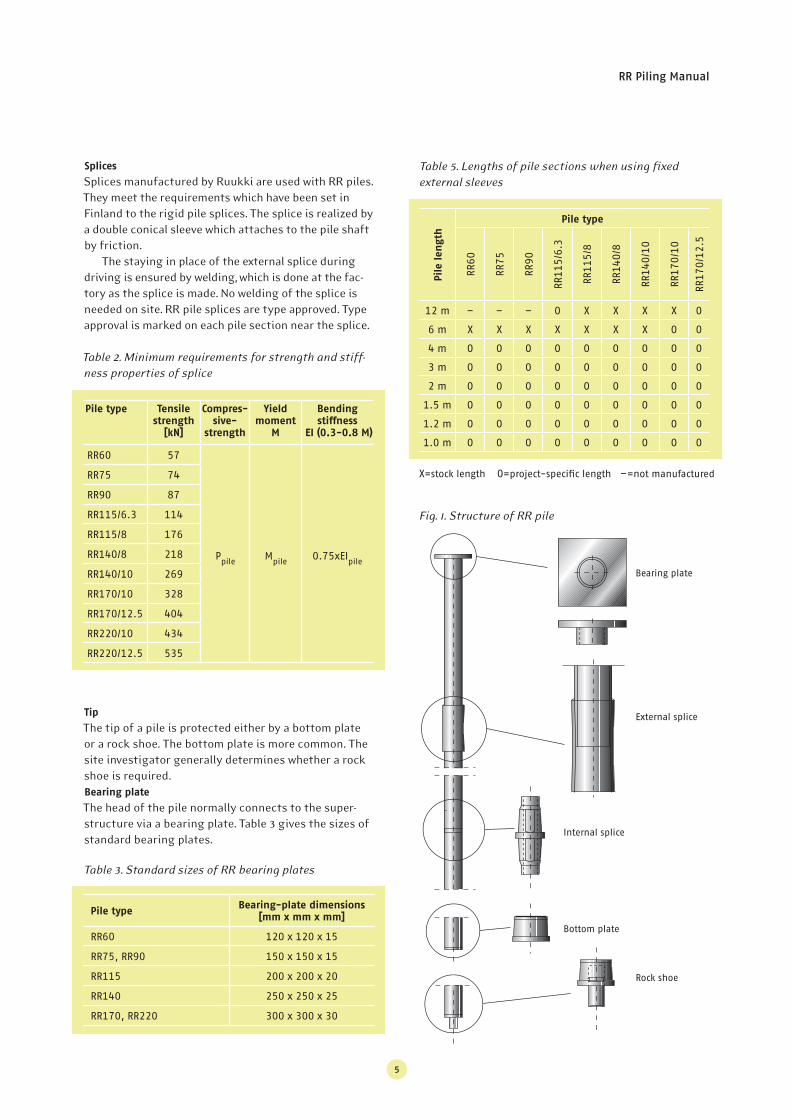
Fig. 1. Structure of RR pile
Table 5. Lengths of pile sections when using fi xed
external sleeves
Splices
Splices manufactured by Ruukki are used with RR piles.
They meet the requirements which have been set in
Finland to the rigid pile splices. The splice is realized by
a double conical sleeve which attaches to the pile shaft
by friction.
The staying in place of the external splice during
driving is ensured by welding, which is done at the fac-
tory as the splice is made. No welding of the splice is
needed on site. RR pile splices are type approved. Type
approval is marked on each pile section near the splice.
Table 2. Minimum requirements for strength and stiff-
ness properties of splice
Pile type Tensile
strength
[kN]
Compres-
sive-
strength
Yield
moment
M
Bending
stiffness
EI (0.3-0.8 M)
RR60 57
Ppile
Mpile
0.75xEIpile
RR75 74
RR90 87
RR115/6.3 114
RR115/8 176
RR140/8 218
RR140/10 269
RR170/10 328
RR170/12.5 404
RR220/10 434
RR220/12.5 535
Tip
The tip of a pile is protected either by a bottom plate
or a rock shoe. The bottom plate is more common. The
site investigator generally determines whether a rock
shoe is required.
Bearing plate
The head of the pile normally connects to the super-
structure via a bearing plate. Table 3 gives the sizes of
standard bearing plates.
Pile typeBearing-plate dimensions
[mm x mm x mm]
RR60 120 x 120 x 15
RR75, RR90 150 x 150 x 15
RR115 200 x 200 x 20
RR140 250 x 250 x 25
RR170, RR220 300 x 300 x 30
Table 3. Standard sizes of RR bearing plates
Pile length
Pile type
RR6
0
RR7
5
RR9
0
RR1
15
/6.3
RR1
15
/8
RR1
40
/8
RR1
40
/10
RR1
70
/10
RR1
70
/12
.5
12 m – – – O X X X X O
6 m X X X X X X X O O
4 m O O O O O O O O O
3 m O O O O O O O O O
2 m O O O O O O O O O
1.5 m O O O O O O O O O
1.2 m O O O O O O O O O
1.0 m O O O O O O O O O
X=stock length O=project-specifi c length –=not manufactured
Bearing plate
External splice
Internal splice
Bottom plate
Rock shoe
6
A sufficient number of blows makes the dowel of the
RR pile’s rock shoe penetrate into rock so that the whole
base of the pile becomes bearing. The bearing capacity
of a pile bearing on rock is not determined by its
geotechnical bearing capacity – it is defined either by
structural bearing capacity or buckling resistance. At the
end of driving, permanent set of pile and temporary
elastic compression of pile and soil must be checked.
Bearing capacity of pile bearing on ground
The geotechnical bearing capacity of a pile bearing
on ground may be clearly smaller than its structural
bearing capacity.
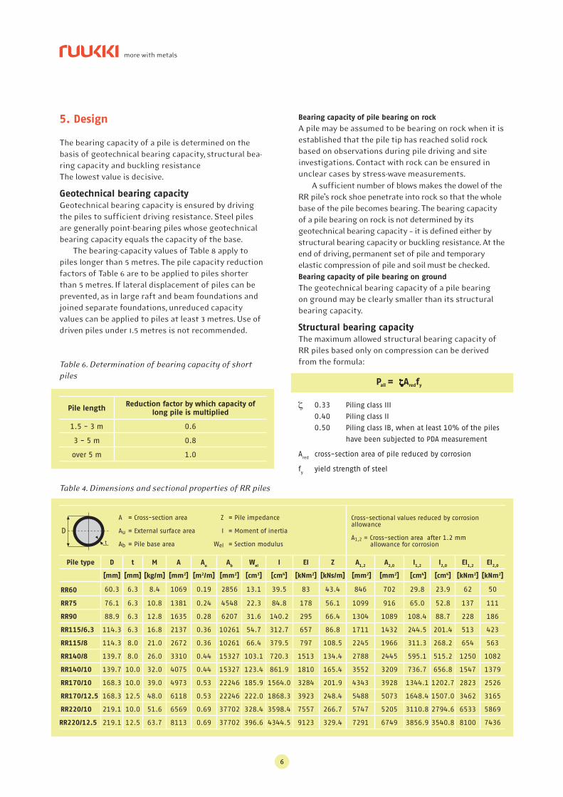
Structural bearing capacity
The maximum allowed structural bearing capacity of
RR piles based only on compression can be derived
from the formula:
Bearing capacity of pile bearing on rock
A pile may be assumed to be bearing on rock when it is
established that the pile tip has reached solid rock
based on observations during pile driving and site
investigations. Contact with rock can be ensured in
unclear cases by stress-wave measurements.
5. Design
The bearing capacity of a pile is determined on the
basis of geotechnical bearing capacity, structural bea-
ring capacity and buckling resistance
The lowest value is decisive.
Geotechnical bearing capacity
Geotechnical bearing capacity is ensured by driving
the piles to sufficient driving resistance. Steel piles
are generally point-bearing piles whose geotechnical
bearing capacity equals the capacity of the base.
The bearing-capacity values of Table 8 apply to
piles longer than 5 metres. The pile capacity reduction
factors of Table 6 are to be applied to piles shorter
than 5 metres. If lateral displacement of piles can be
prevented, as in large raft and beam foundations and
joined separate foundations, unreduced capacity
values can be applied to piles at least 3 metres. Use of
driven piles under 1.5 metres is not recommended.
Table 6. Determination of bearing capacity of short
piles
Pile lengthReduction factor by which capacity of
long pile is multiplied
1.5 - 3 m 0.6
3 - 5 m 0.8
over 5 m 1.0
Table 4. Dimensions and sectional properties of RR piles
Pile type D t M A Au
Ab W
el I EI Z A
1,2 A
2,0 I
1,2 I
2,0 EI
1,2 EI
2,0
[mm] [mm] [kg/m] [mm2] [m2/m] [mm2] [cm3] [cm4] [kNm2] [kNs/m] [mm2] [mm2] [cm4] [cm4] [kNm2] [kNm2]
RR60 60.3 6.3 8.4 1069 0.19 2856 13.1 39.5 83 43.4 846 702 29.8 23.9 62 50
RR75 76.1 6.3 10.8 1381 0.24 4548 22.3 84.8 178 56.1 1099 916 65.0 52.8 137 111
RR90 88.9 6.3 12.8 1635 0.28 6207 31.6 140.2 295 66.4 1304 1089 108.4 88.7 228 186
RR115/6.3 114.3 6.3 16.8 2137 0.36 10261 54.7 312.7 657 86.8 1711 1432 244.5 201.4 513 423
RR115/8 114.3 8.0 21.0 2672 0.36 10261 66.4 379.5 797 108.5 2245 1966 311.3 268.2 654 563
RR140/8 139.7 8.0 26.0 3310 0.44 15327 103.1 720.3 1513 134.4 2788 2445 595.1 515.2 1250 1082
RR140/10 139.7 10.0 32.0 4075 0.44 15327 123.4 861.9 1810 165.4 3552 3209 736.7 656.8 1547 1379
RR170/10 168.3 10.0 39.0 4973 0.53 22246 185.9 1564.0 3284 201.9 4343 3928 1344.1 1202.7 2823 2526
RR170/12.5 168.3 12.5 48.0 6118 0.53 22246 222.0 1868.3 3923 248.4 5488 5073 1648.4 1507.0 3462 3165
RR220/10 219.1 10.0 51.6 6569 0.69 37702 328.4 3598.4 7557 266.7 5747 5205 3110.8 2794.6 6533 5869
RR220/12.5 219.1 12.5 63.7 8113 0.69 37702 396.6 4344.5 9123 329.4 7291 6749 3856.9 3540.8 8100 7436
A = Cross-section area Z = Pile impedance
Au = External surface area I = Moment of inertia
Ab = Pile base area Wel = Section modulus
Cross-sectional values reduced by corrosion allowance
A1,2 = Cross-section area after 1.2 mm allowance for corrosion
0.33 Piling class III
0.40 Piling class II
0.50 Piling class IB, when at least 10% of the piles
have been subjected to PDA measurement
Ared
cross-section area of pile reduced by corrosion
fy yield strength of steel
Pall = Aredfy
D
RR Piling Manual
7
Table 7. Corrosion allowances [mm]
according to EN 1993-5 Eurocode
3: Design of Steel Structures – Part 5: Piling
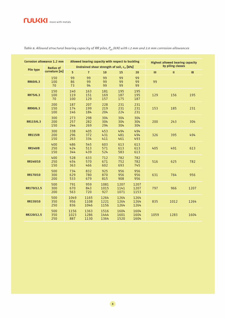
Table 8 shows the allowed structural bearing capacity
of piles by classes. Bearing capacities have been calcu-
lated using three different radi of curvature conside-
ring the impact of buckling in soil layers providing
poor lateral support. The largest radius of curvature is
generally realized when using long pile sections (6-12
m) and the piles are driven into soil layers containing
no stones. Correspondingly, the smallest radius is nor-
mally realized when using short (1-2 m) pile sections in
diffi cult soil conditions.
Corrosion
Separate corrosion investigations are normally not
needed except in industrial, or other possibly polluted,
sites and with soil layers containing sulphide clay.
The surrounding conditions are considered in esti-
mating the corrosion rate of RR piles. Corrosion is
usually taken into account in the form of corrosion
allowance. The magnitude of the corrosion allowance
depends on the designed service life of the structure
and estimated corrosion rate.
In clean soil corrosion is generally so low that piles
can be protected by increasing wall thickness. The
service life of foundations is generally estimated at
100 years, which sets the recommended corrosion
allowance at 1.2-2 mm according to Eurocode 3 which
deals with the design of steel structures (Table 7).
Internal corrosion of piles with a closed base and top is
so minimal that it can be ignored.
Piles may be concreted inside if necessary. Then,
they can be dimensioned as a composite structure. In
difficult corrosive conditions, such as polluted soils,
protection may be realized by, for instance, concrete
structures. Separate protection may also be provided
by organic or inorganic surface treatments or cathodic
protection. When using them, one must consider their
durability during installation and service life. Surface
treatments may become damaged when piles are
installed in a stony or similar “scratching” layer. In
such instances the rate of the occurring pit corrosion
may exceed that of even corrosion.
If cathodic protection is used, the life time of the
protection is to be considered.
Attachment of pile to superstructure
The head of a pile generally attaches to the superstruc-
ture via a bearing plate. The size of the plate must be
selected on the basis of the strength of the superstruc-
ture. The connection of the pile and the superstructure
can be dimensioned as a hinge. An exception are piles
shorter than 3 m. They should be attached to the
superstructure by a rigid joint. A pile normally joins
the superstructure rigidly when at least a 2 x D section
of the pile head (200 mm at a minimum) is set in conc-
rete. When the poured concrete is vibrated, it must be
ensured that the bearing plate cap does not rise.
If the groundwater level of the surroundings is
higher than the pile cut-off level, bearing plates must
be welded tightly to the piles.
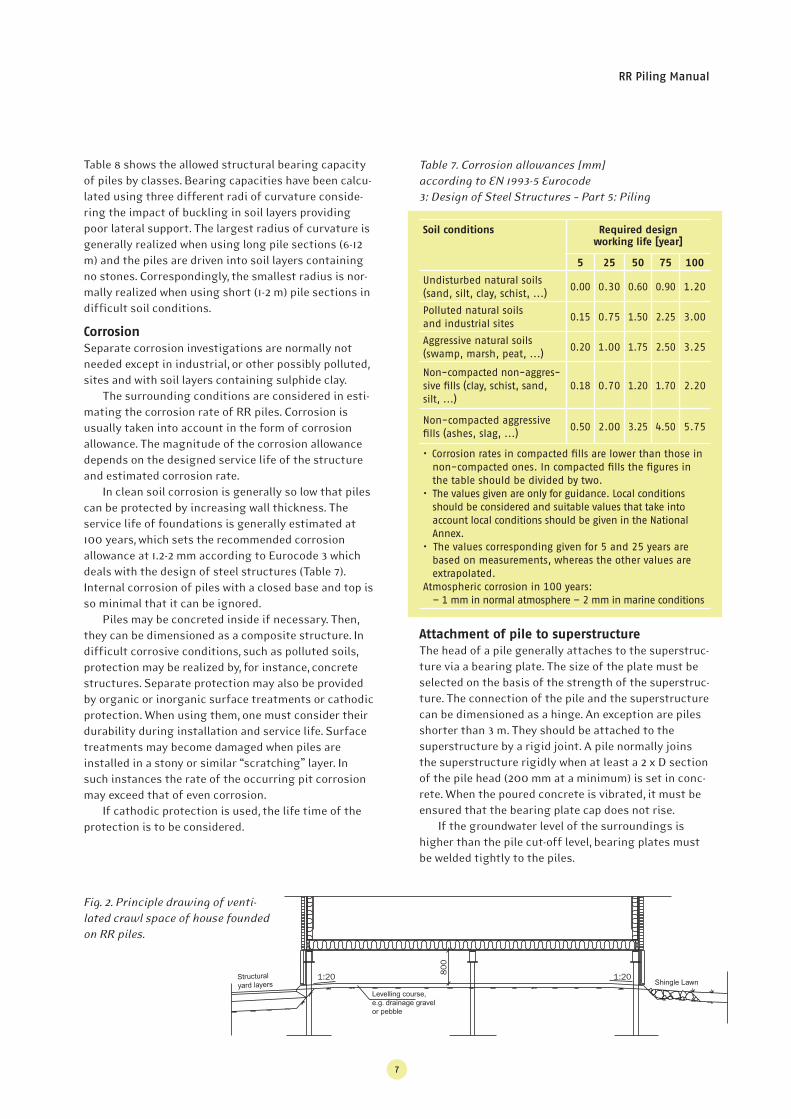
Structuralyard layers
Levelling course, e.g. drainage gravel or pebble
Shingle Lawn
Fig. 2. Principle drawing of venti-
lated crawl space of house founded
on RR piles.
Soil conditions Required design
working life [year]
5 25 50 75 100
Undisturbed natural soils (sand, silt, clay, schist, ...)
0.00 0.30 0.60 0.90 1.20
Polluted natural soilsand industrial sites
0.15 0.75 1.50 2.25 3.00
Aggressive natural soils (swamp, marsh, peat, ...)
0.20 1.00 1.75 2.50 3.25
Non-compacted non-aggres-sive fi lls (clay, schist, sand, silt, ...)
0.18 0.70 1.20 1.70 2.20
Non-compacted aggressive fi lls (ashes, slag, ...)
0.50 2.00 3.25 4.50 5.75
• Corrosion rates in compacted fi lls are lower than those in non-compacted ones. In compacted fi lls the fi gures in the table should be divided by two.
• The values given are only for guidance. Local conditions should be considered and suitable values that take into account local conditions should be given in the National Annex.
• The values corresponding given for 5 and 25 years are based on measurements, whereas the other values are extrapolated.
Atmospheric corrosion in 100 years:– 1 mm in normal atmosphere – 2 mm in marine conditions
8
Table 8. Allowed structural bearing capacity of RR piles, Pall [kN] with 1.2 mm and 2.0 mm corrosion allowances
Corrosion allowance 1.2 mm Allowed bearing capacity with respect to buckling Highest allowed bearing capacity
by piling classes
Pile typeRadius of
curvature [m]
Undrained shear strength of soil, cuk [kPa]
5 7 10 15 20 III II IB
RR60/6.3
15010070
998673
999994
999999
999999
999999
99
RR75/6.3
15010070
140119100
163151129
181169157
195187175
195195187
129 156 195
RR90/6.3
200150100
187174146
207199184
228219204
231231224
231231231
153 185 231
RR115/6.3
300200150
273257244
298282269
304304294
304304304
304304304
200 243 304
RR115/8
300200150
338296263
405372334
453431411
494481461
494494493
326 395 494
RR140/8
400250150
486424344
545513439
603571524
613613583
613613613
405 491 613
RR140/10
400250150
528454363
633570466
712671602
782752693
782782745
516 625 782
RR170/10
500300200
734629533
832780679
925870815
956956908
956956956
631 764 956
RR170/12.5
500300200
791670563
959843720
10811015927
120711411071
120712071153
797 966 1207
RR220/10
500350250
1049956836
116511081046
126412211156
126412641264
126412641264
835 1012 1264
RR220/12.5
500350250
11561023887
136312861130
151614441364
160416011520
160416041604
1059 1283 1604
RR Piling Manual
9
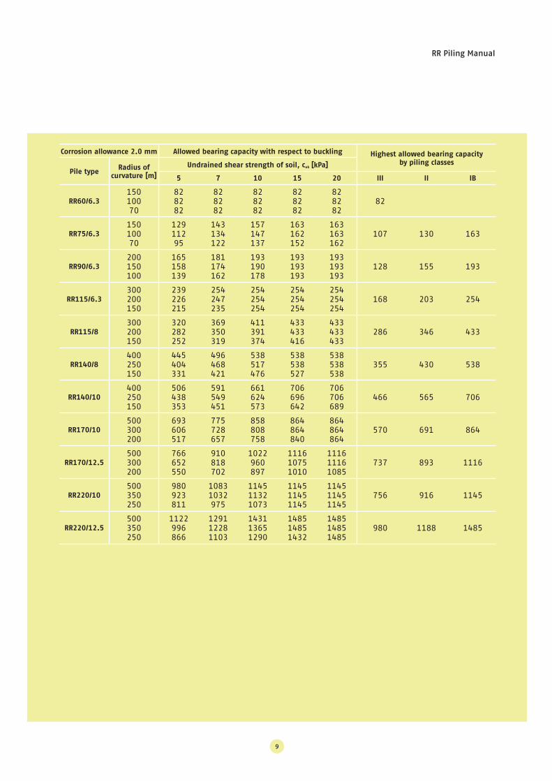
Corrosion allowance 2.0 mm Allowed bearing capacity with respect to buckling Highest allowed bearing capacity
by piling classes
Pile typeRadius of
curvature [m]
Undrained shear strength of soil, cuk [kPa]
5 7 10 15 20 III II IB
RR60/6.3
15010070
828282
828282
828282
828282
828282
82
RR75/6.3
15010070
12911295
143134122
157147137
163162152
163163162
107 130 163
RR90/6.3
200150100
165158139
181174162
193190178
193193193
193193193
128 155 193
RR115/6.3
300200150
239226215
254247235
254254254
254254254
254254254
168 203 254
RR115/8
300200150
320282252
369350319
411391374
433433416
433433433
286 346 433
RR140/8
400250150
445404331
496468421
538517476
538538527
538538538
355 430 538
RR140/10
400250150
506438353
591549451
661624573
706696642
706706689
466 565 706
RR170/10
500300200
693606517
775728657
858808758
864864840
864864864
570 691 864
RR170/12.5
500300200
766652550
910818702
1022960897
111610751010
111611161085
737 893 1116
RR220/10
500350250
980923811
10831032975
114511321073
114511451145
114511451145
756 916 1145
RR220/12.5
500350250
1122996866
129112281103
143113651290
148514851432
148514851485
980 1188 1485
10
Pile bearing capacity may also be confirmed by static
load tests.
Dynamic load tests
The geotechnical bearing capacity of class IB piles
must be confirmed by load tests.
Presently, dynamic load tests are suited for setting
the end-of-driving criterion when using a drop hammer,
a hydraulic hammer or a pneumatic hammer. If a hyd-
raulic ram is used, end-of-driving criteria have to be set
based on comparison measurements with other dri-
ving equipment.
The person conducting the dynamic load tests as
well as the analyzer of the results must be familiar
with driven piling and especially with pile behaviour
during driving stress while also possessing adequate
knowledge about stress-wave theory. Stress-wave
measurements allow setting end-of-driving criteria for
piles that provide the required ultimate geotechnical
bearing capacity.
At sites where class IB piles are used, dynamic load
tests should be performed for each pile size, pile type
and soil-condition type. At least 10 percent of the piles
should be tested.
In addition to geotechnical bearing capacity, dyna-
mic load tests also provide information about the
behaviour and integrity of a pile and the condition and
effectiveness of piling equipment.
7. Execution
Different driving methods
RR piles can be driven with different types of equip-
ment. The driving equipment divide into three classes:
• Drop and hydraulic hammers
• Pneumatic hammers
• Hydraulic rams
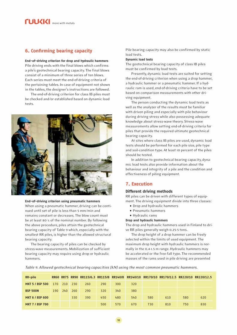
Drop and hydraulic hammers
The drop and hydraulic hammers used in Finland to dri-
ve RR piles generally weigh 0.25-5 tons.
The drop height of a drop hammer can be freely
selected within the limits of used equipment. The
maximum drop height with hydraulic hammers is nor-
mally in the 0.4-1.5 m range. Hydraulic hammers may
be accelerated or the free-fall type. The recommended
masses of the rams used in pile driving are presented
6. Confi rming bearing capacity
End-of-driving criterion for drop and hydraulic hammers
Pile driving ends with the final blows which confirms
a pile’s geotechnical bearing capacity. The final blows
consist of a minimum of three series of ten blows.
Each series must meet the end-of-driving criteria of
the pertaining tables. In case of equipment not shown
in the tables, the designer’s instructions are followed.
The end-of-driving criterion for class IB piles must
be checked and/or established based on dynamic load
tests.
End-of-driving criterion using pneumatic hammers
When using a pneumatic hammer, driving can be conti-
nued until set of pile is less than 5 mm/min and
remains constant or decreases. The blow count must
be at least 80 % of the nominal number. By following
the above procedure, piles attain the geotechnical
bearing capacity of Table 9 which, especially with the
smallest RR piles, is higher than the allowed structural
bearing capacity.
The bearing capacity of piles can be checked by
stress-wave measurements. Mobilization of sufficient
bearing capacity may require using drop or hydraulic
hammers.
Table 9. Allowed geotechnical bearing capacities [kN] using the most common pneumatic hammers.
RR-pile RR60 RR75 RR90 RR115/6.3 RR115/8 RR140/8 RR140/10 RR170/10 RR170/12.5 RR220/10 RR220/12.5
MKT 5 / BSP 500 170 210 230 260 290 300 320
BSP 500N 190 240 260 290 320 340 380
MKT 6 / BSP 600 330 390 450 480 540 580 610 580 620
MKT 7 / BSP 700 500 570 670 730 810 750 830
RR Piling Manual
11
in more detail in the RR Piling Handbook.
Pneumatic hammers
These equipment are operated by compressed air and
deliver 100-400 blows per minute. The recommended
masses of the moving part of pneumatic hammers are
presented in the RR Piling Handbook.
Hydraulic rams
Hydraulic rams generally deliver 300-1,000 blows per
minute. They are hydraulically operated. Pile driving
with the lightest rams corresponds most closely to
vibrating. Vibration reduces the friction or cohesion
between the skin of the pile and soil, and the blows are
delivered to the pile base. This causes the pile to penet-
rate into the ground.
The lightest hydraulic rams are poorly suited for
driving piles in stony soil conditions.
Pile driving
A pile must be driven without long interruptions or
causing damage to the pile. Blows must be parallel to
the longitudinal axis and centred. Drop heights excee-
ding those shown in the end-of- driving table must not
be used.
The pile tip is equipped with a bottom plate or a
rock shoe whose attachment to the pile pipe must be
secured before driving commences.
RR piles are driven by two methods depending on
the location of the splice. The splice may be either
external or internal. An external splice may be at the
head or bottom of the pile section.
When the splice is at the bottom of the section,
driving is usually commenced with a section contai-
ning no splice, for instance, a waste end of a previously
cut pipe. The pile is driven into ground the factory-cut
end first.
When driving a pile with the splice up, an adapter is
to be used to transmit the blow past the external fricti-
on splice to the pile pipe. The pile splice must under no
conditions be struck!
When the first section has been driven into the
ground, the condition of the pile head is checked. If the
pile needs to be spliced, the instructions of the next
chapter are to be followed.
In soft soil layers the pile must not be driven using
the drop height required by the end-of-driving criteri-
on; considerably lower driving energy must be applied.
Using excessive energy in soft soil layers may result in
considerable tensile stresses in the pile that may cau-
se splices to open. Pile splices close permanently only
at the end-of-driving phase.
Pile driving may be discontinued when the pile
reaches the designed depth and meets its end-of-dri-
ving criterion.
The level of the pile head must be determined after
the final blows. The head level must be checked after
installing a pile group as the piles may rise when a
dense, bearing soil layer is overlaid only by soft ones.
Piles are to be subjected to redriving where necessary.
Splicing
External splice
A pile is spliced by installing the next section on top
of the previous one. In soft soil layers splices may
close fi nally only at the end-of-driving phase.
Internal splice
An internal splice is made at the head of a pile so that
the groove in the splicing insert fi ts over the
longitudinal weld of the pile. The insert is pressed or
tapped carefully in part of the way leaving a gap bet-
ween the pile and the fl ange of the insert. The next pile
section is then installed onto the insert. Splices close
permanently only at the end of driving.
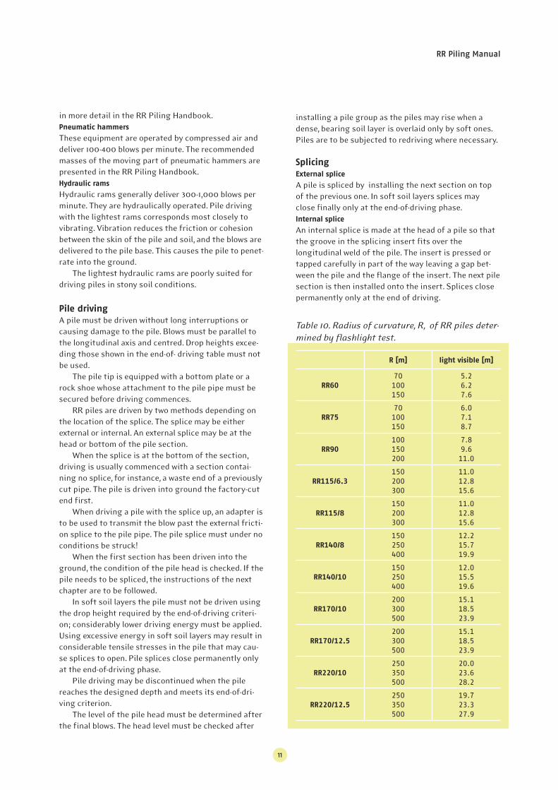
Table 10. Radius of curvature, R, of RR piles deter-
mined by fl ashlight test.
R [m] light visible [m]
RR60
70100150
5.26.27.6
RR75
70100150
6.07.18.7
RR90
100150200
7.89.6
11.0
RR115/6.3
150200300
11.012.815.6
RR115/8
150200300
11.012.815.6
RR140/8
150250400
12.215.719.9
RR140/10
150250400
12.015.519.6
RR170/10
200300500
15.118.523.9
RR170/12.5
200300500
15.118.523.9
RR220/10
250350500
20.023.628.2
RR220/12.5
250350500
19.723.327.9
12
Cutting of piles
Pile ends must be closed after driving in order to pre-
vent unwanted material from getting inside. Moreover,
low lying open pile ends are also a safety hazard.
Piles are cut at the planned height at right angles
to the pile axis. The maximum allowed slope of the top
from a plane perpendicular to the pile axis is 1:50
unless otherwise indicated in the designs. The ends of
piles must be closed after cutting.
8. Monitoring
A piling record in accordance with the RR Piling Hand-
book is kept on piling work. All observations regarding
factors affecting bearing capacity are to be entered in
it.
The end-of-driving criteria for piles must be met.
Final set should decrease to the required value, and
elastic compression must not be higher than normal.
The straightness of a pile must be checked after
driving. This can be done using an inclinometer or by
probing with a gauge. Pile straightness may also be
evaluated by lowering a flashlight down a pile in accor-
dance with Table 10. If the radius of curvature of a pile
is below the requirement of the piling plan, further
measures must be agreed with the structural and
geotechnical engineer.
RR Piling Manual
13
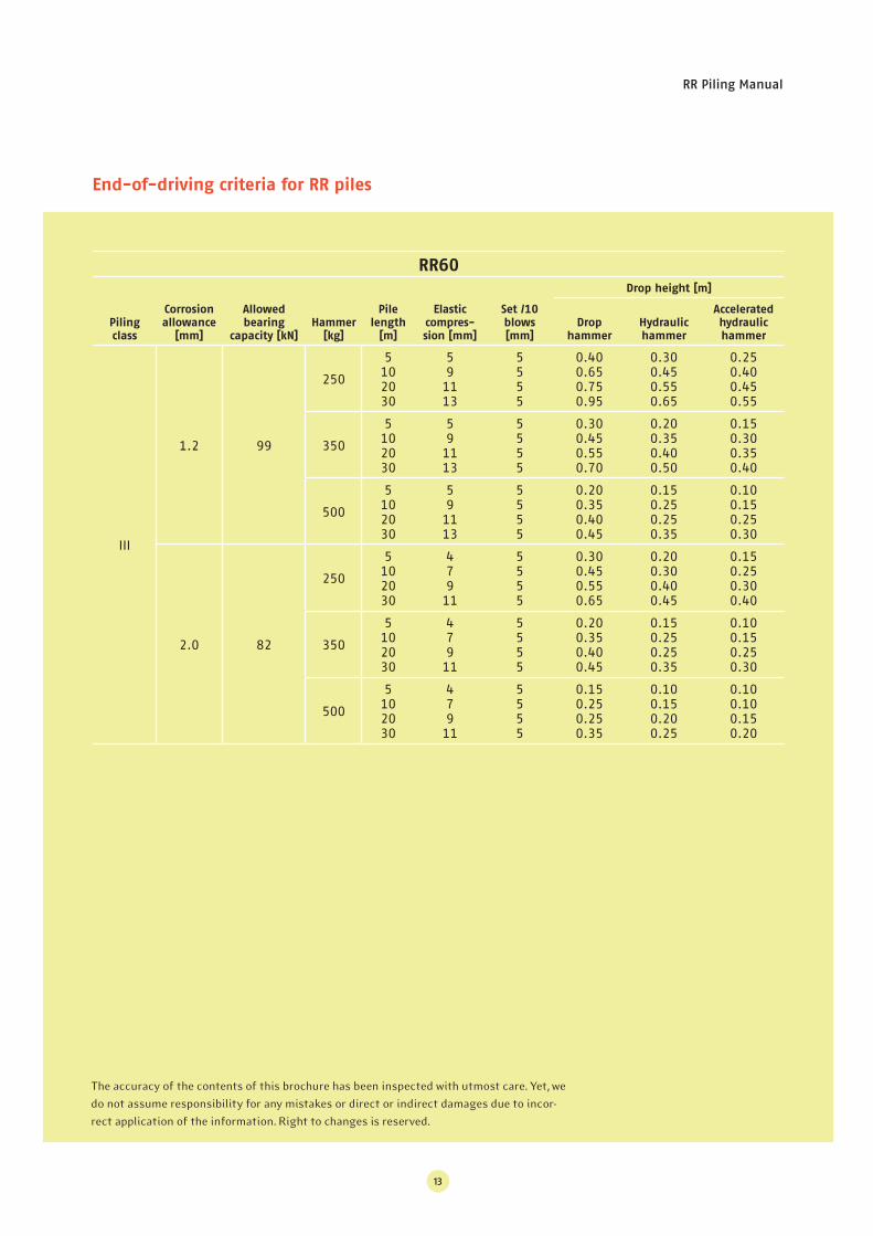
End-of-driving criteria for RR piles
RR60
Piling
class
Corrosion
allowance
[mm]
Allowed
bearing
capacity [kN]
Hammer
[kg]
Pile
length
[m]
Elastic
compres-
sion [mm]
Set /10
blows
[mm]
Drop height [m]
Drop
hammer
Hydraulic
hammer
Accelerated
hydraulic
hammer
III
1.2 99
250
5102030
591113
5555
0.400.650.750.95
0.300.450.550.65
0.250.400.450.55
350
5102030
591113
5555
0.300.450.550.70
0.200.350.400.50
0.150.300.350.40
500
5102030
591113
5555
0.200.350.400.45
0.150.250.250.35
0.100.150.250.30
2.0 82
250
5102030
47911
5555
0.300.450.550.65
0.200.300.400.45
0.150.250.300.40
350
5102030
47911
5555
0.200.350.400.45
0.150.250.250.35
0.100.150.250.30
500
5102030
47911
5555
0.150.250.250.35
0.100.150.200.25
0.100.100.150.20
The accuracy of the contents of this brochure has been inspected with utmost care. Yet, we
do not assume responsibility for any mistakes or direct or indirect damages due to incor-
rect application of the information. Right to changes is reserved.
14
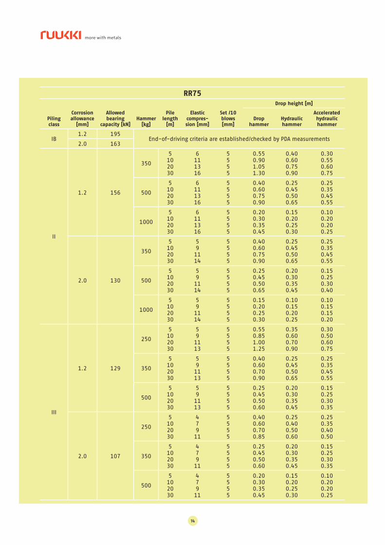
RR75
Piling
class
Corrosion
allowance
[mm]
Allowed
bearing
capacity [kN]
Hammer
[kg]
Pile
length
[m]
Elastic
compres-
sion [mm]
Set /10
blows
[mm]
Drop height [m]
Drop
hammer
Hydraulic
hammer
Accelerated
hydraulic
hammer
IB1.2 195
End-of-driving criteria are established/checked by PDA measurements2.0 163
II
1.2 156
350
5102030
6111316
5555
0.550.901.051.30
0.400.600.750.90
0.300.550.600.75
500
5102030
6111316
5555
0.400.600.750.90
0.250.450.500.65
0.250.350.450.55
1000
5102030
6111316
5555
0.200.300.350.45
0.150.200.250.30
0.100.200.200.25
2.0 130
350
5102030
591114
5555
0.400.600.750.90
0.250.450.500.65
0.250.350.450.55
500
5102030
591114
5555
0.250.450.500.65
0.200.300.350.45
0.150.250.300.40
1000
5102030
591114
5555
0.150.200.250.30
0.100.150.200.25
0.100.150.150.20
III
1.2 129
250
5102030
591113
5555
0.550.851.001.25
0.350.600.700.90
0.300.500.600.75
350
5102030
591113
5555
0.400.600.700.90
0.250.450.500.65
0.250.350.450.55
500
5102030
591113
5555
0.250.450.500.60
0.200.300.350.45
0.150.250.300.35
2.0 107
250
5102030
47911
5555
0.400.600.700.85
0.250.400.500.60
0.250.350.400.50
350
5102030
47911
5555
0.250.450.500.60
0.200.300.350.45
0.150.250.300.35
500
5102030
47911
5555
0.200.300.350.45
0.150.200.250.30
0.100.200.200.25
RR Piling Manual
15
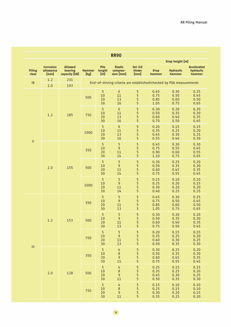
RR90
Piling
class
Corrosion
allowance
[mm]
Allowed
bearing
capacity [kN]
Hammer
[kg]
Pile
length
[m]
Elastic
compres-
sion [mm]
Set /10
blows
[mm]
Drop height [m]
Drop
hammer
Hydraulic
hammer
Accelerated
hydraulic
hammer
IB1.2 231
End-of-driving criteria are established/checked by PDA measurements2.0 193
II
1.2 185
500
5102030
6111316
5555
0.450.750.851.05
0.300.500.600.75
0.250.450.500.65
750
5102030
6111316
5555
0.300.500.600.70
0.200.350.400.50
0.200.300.350.45
1000
5102030
6111316
5555
0.200.350.450.55
0.150.250.300.40
0.150.200.250.30
2.0 155
350
5102030
591114
5555
0.450.750.901.10
0.300.550.600.75
0.300.450.550.65
500
5102030
591114
5555
0.300.500.600.75
0.250.350.450.55
0.200.300.350.45
1000
5102030
591114
5555
0.150.250.300.40
0.100.200.200.25
0.100.150.200.25
III
1.2 153
350
5102030
591113
5555
0.450.750.851.05
0.300.500.600.75
0.250.450.500.65
500
5102030
591113
5555
0.300.500.600.75
0.200.350.400.50
0.200.300.350.45
750
5102030
591113
5555
0.200.350.400.50
0.150.250.300.35
0.150.200.250.30
2.0 128
350
5102030
48911
5555
0.300.500.600.75
0.250.350.450.55
0.200.300.350.45
500
5102030
48911
5555
0.250.350.450.50
0.150.250.300.35
0.150.200.250.30
750
5102030
48911
5555
0.150.250.300.35
0.100.150.200.25
0.100.100.150.20
16
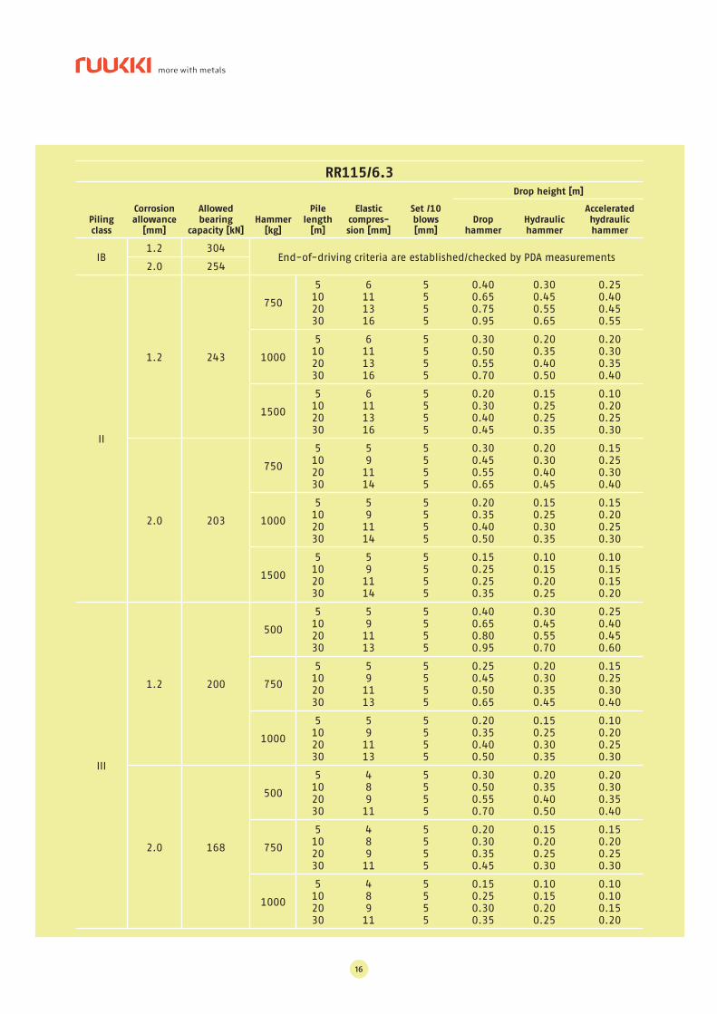
RR115/6.3
Piling
class
Corrosion
allowance
[mm]
Allowed
bearing
capacity [kN]
Hammer
[kg]
Pile
length
[m]
Elastic
compres-
sion [mm]
Set /10
blows
[mm]
Drop height [m]
Drop
hammer
Hydraulic
hammer
Accelerated
hydraulic
hammer
IB1.2 304
End-of-driving criteria are established/checked by PDA measurements2.0 254
II
1.2 243
750
5102030
6111316
5555
0.400.650.750.95
0.300.450.550.65
0.250.400.450.55
1000
5102030
6111316
5555
0.300.500.550.70
0.200.350.400.50
0.200.300.350.40
1500
5102030
6111316
5555
0.200.300.400.45
0.150.250.250.35
0.100.200.250.30
2.0 203
750
5102030
591114
5555
0.300.450.550.65
0.200.300.400.45
0.150.250.300.40
1000
5102030
591114
5555
0.200.350.400.50
0.150.250.300.35
0.150.200.250.30
1500
5102030
591114
5555
0.150.250.250.35
0.100.150.200.25
0.100.150.150.20
III
1.2 200
500
5102030
591113
5555
0.400.650.800.95
0.300.450.550.70
0.250.400.450.60
750
5102030
591113
5555
0.250.450.500.65
0.200.300.350.45
0.150.250.300.40
1000
5102030
591113
5555
0.200.350.400.50
0.150.250.300.35
0.100.200.250.30
2.0 168
500
5102030
48911
5555
0.300.500.550.70
0.200.350.400.50
0.200.300.350.40
750
5102030
48911
5555
0.200.300.350.45
0.150.200.250.30
0.150.200.250.30
1000
5102030
48911
5555
0.150.250.300.35
0.100.150.200.25
0.100.100.150.20
RR Piling Manual
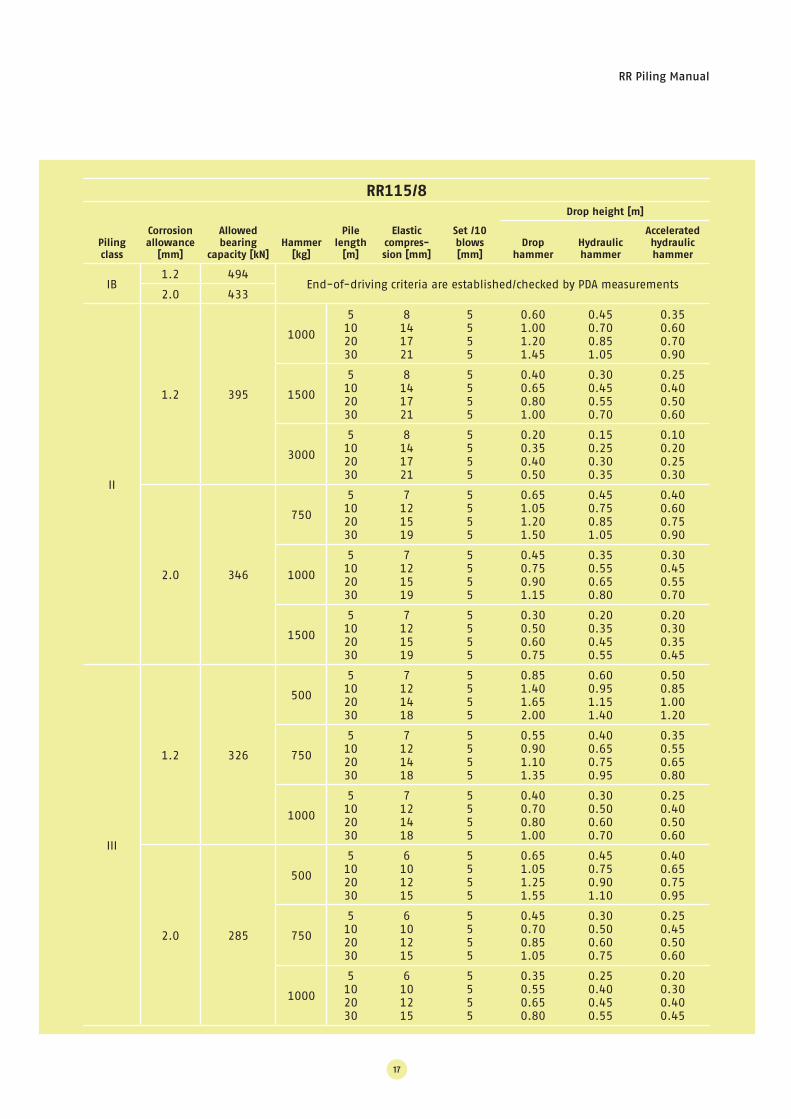
17
RR115/8
Piling
class
Corrosion
allowance
[mm]
Allowed
bearing
capacity [kN]
Hammer
[kg]
Pile
length
[m]
Elastic
compres-
sion [mm]
Set /10
blows
[mm]
Drop height [m]
Drop
hammer
Hydraulic
hammer
Accelerated
hydraulic
hammer
IB1.2 494
End-of-driving criteria are established/checked by PDA measurements2.0 433
II
1.2 395
1000
5102030
8141721
5555
0.601.001.201.45
0.450.700.851.05
0.350.600.700.90
1500
5102030
8141721
5555
0.400.650.801.00
0.300.450.550.70
0.250.400.500.60
3000
5102030
8141721
5555
0.200.350.400.50
0.150.250.300.35
0.100.200.250.30
2.0 346
750
5102030
7121519
5555
0.651.051.201.50
0.450.750.851.05
0.400.600.750.90
1000
5102030
7121519
5555
0.450.750.901.15
0.350.550.650.80
0.300.450.550.70
1500
5102030
7121519
5555
0.300.500.600.75
0.200.350.450.55
0.200.300.350.45
III
1.2 326
500
5102030
7121418
5555
0.851.401.652.00
0.600.951.151.40
0.500.851.001.20
750
5102030
7121418
5555
0.550.901.101.35
0.400.650.750.95
0.350.550.650.80
1000
5102030
7121418
5555
0.400.700.801.00
0.300.500.600.70
0.250.400.500.60
2.0 285
500
5102030
6101215
5555
0.651.051.251.55
0.450.750.901.10
0.400.650.750.95
750
5102030
6101215
5555
0.450.700.851.05
0.300.500.600.75
0.250.450.500.60
1000
5102030
6101215
5555
0.350.550.650.80
0.250.400.450.55
0.200.300.400.45
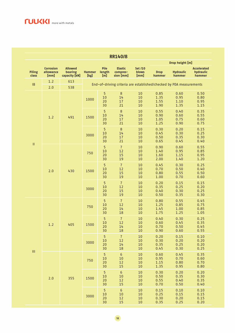
18
RR140/8
Piling
class
Corrosion
allowance
[mm]
Allowed
bearing
capacity [kN]
Hammer
[kg]
Pile
length
[m]
Elastic
compres-
sion [mm]
Set /10
blows
[mm]
Drop height [m]
Drop
hammer
Hydraulic
hammer
Accelerated
hydraulic
hammer
IB1.2 613
End-of-driving criteria are established/checked by PDA measurements2.0 538
II
1.2 491
1000
5102030
8141721
10101010
0.851.351.551.90
0.600.951.101.35
0.500.800.951.15
1500
5102030
8141721
10101010
0.550.901.051.25
0.400.600.750.90
0.350.550.600.75
3000
5102030
8141721
10101010
0.300.450.500.65
0.200.300.350.45
0.150.250.300.40
2.0 430
750
5102030
7121519
10101010
0.901.401.602.00
0.600.951.151.40
0.550.850.951.20
1500
5102030
7121519
10101010
0.450.700.801.00
0.300.500.550.70
0.250.400.500.60
3000
5102030
7121519
10101010
0.200.350.400.50
0.150.250.300.35
0.150.200.250.30
III
1.2 405
750
5102030
7121418
10101010
0.801.251.451.75
0.550.851.001.25
0.450.750.851.05
1500
5102030
7121418
10101010
0.400.600.700.90
0.300.450.500.60
0.250.350.450.55
3000
5102030
7121418
10101010
0.200.300.350.45
0.150.200.250.30
0.100.200.200.25
2.0 355
750
5102030
6101215
10101010
0.600.951.151.35
0.450.700.800.95
0.350.600.700.80
1500
5102030
6101215
10101010
0.300.500.550.70
0.200.350.400.50
0.200.300.350.40
3000
5102030
6101215
10101010
0.150.250.300.35
0.100.150.200.25
0.100.150.150.20
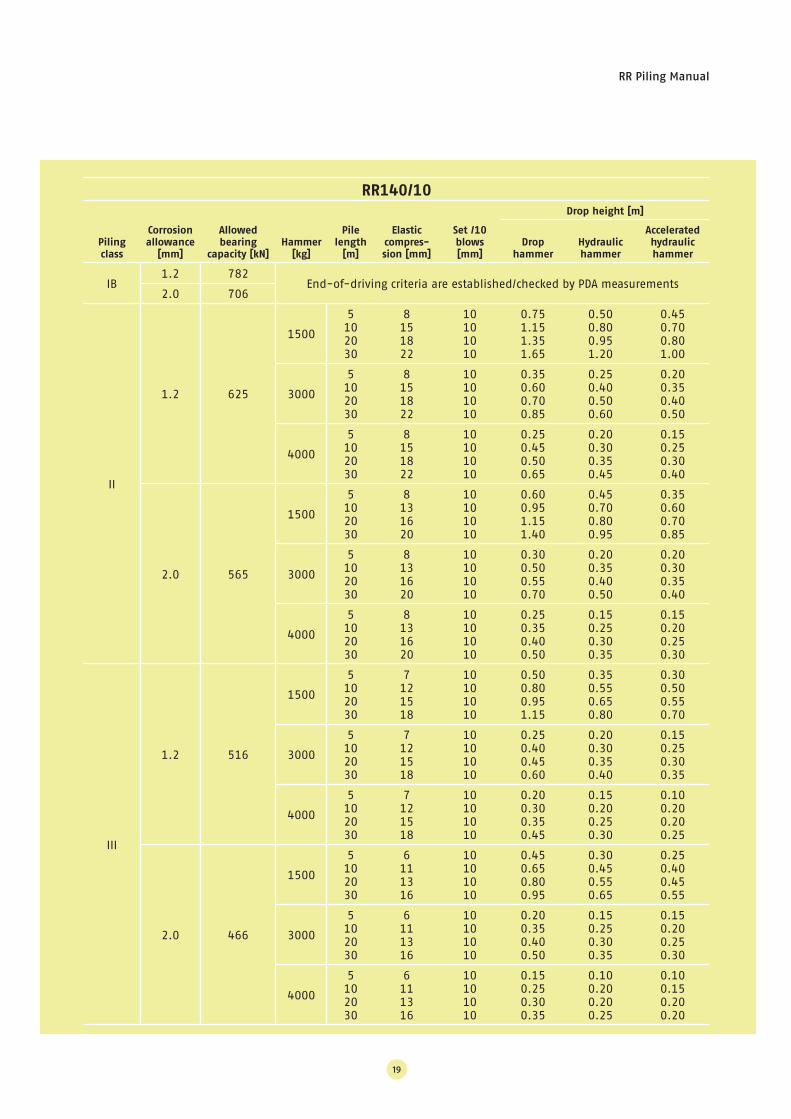
RR Piling Manual
19
RR140/10
Piling
class
Corrosion
allowance
[mm]
Allowed
bearing
capacity [kN]
Hammer
[kg]
Pile
length
[m]
Elastic
compres-
sion [mm]
Set /10
blows
[mm]
Drop height [m]
Drop
hammer
Hydraulic
hammer
Accelerated
hydraulic
hammer
IB1.2 782
End-of-driving criteria are established/checked by PDA measurements2.0 706
II
1.2 625
1500
5102030
8151822
10101010
0.751.151.351.65
0.500.800.951.20
0.450.700.801.00
3000
5102030
8151822
10101010
0.350.600.700.85
0.250.400.500.60
0.200.350.400.50
4000
5102030
8151822
10101010
0.250.450.500.65
0.200.300.350.45
0.150.250.300.40
2.0 565
1500
5102030
8131620
10101010
0.600.951.151.40
0.450.700.800.95
0.350.600.700.85
3000
5102030
8131620
10101010
0.300.500.550.70
0.200.350.400.50
0.200.300.350.40
4000
5102030
8131620
10101010
0.250.350.400.50
0.150.250.300.35
0.150.200.250.30
III
1.2 516
1500
5102030
7121518
10101010
0.500.800.951.15
0.350.550.650.80
0.300.500.550.70
3000
5102030
7121518
10101010
0.250.400.450.60
0.200.300.350.40
0.150.250.300.35
4000
5102030
7121518
10101010
0.200.300.350.45
0.150.200.250.30
0.100.200.200.25
2.0 466
1500
5102030
6111316
10101010
0.450.650.800.95
0.300.450.550.65
0.250.400.450.55
3000
5102030
6111316
10101010
0.200.350.400.50
0.150.250.300.35
0.150.200.250.30
4000
5102030
6111316
10101010
0.150.250.300.35
0.100.200.200.25
0.100.150.200.20
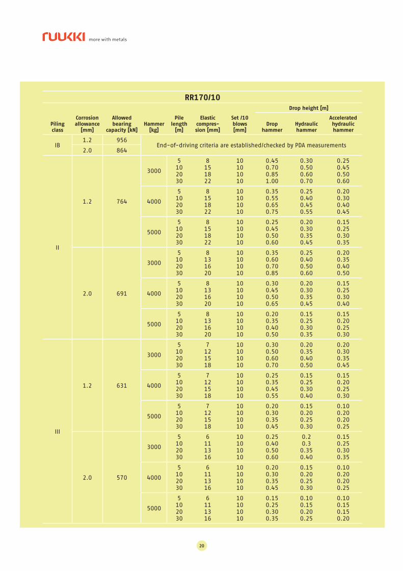
20
RR170/10
Piling
class
Corrosion
allowance
[mm]
Allowed
bearing
capacity [kN]
Hammer
[kg]
Pile
length
[m]
Elastic
compres-
sion [mm]
Set /10
blows
[mm]
Drop height [m]
Drop
hammer
Hydraulic
hammer
Accelerated
hydraulic
hammer
IB1.2 956
End-of-driving criteria are established/checked by PDA measurements2.0 864
II
1.2 764
3000
5102030
8151822
10101010
0.450.700.851.00
0.300.500.600.70
0.250.450.500.60
4000
5102030
8151822
10101010
0.350.550.650.75
0.250.400.450.55
0.200.300.400.45
5000
5102030
8151822
10101010
0.250.450.500.60
0.200.300.350.45
0.150.250.300.35
2.0 691
3000
5102030
8131620
10101010
0.350.600.700.85
0.250.400.500.60
0.200.350.400.50
4000
5102030
8131620
10101010
0.300.450.500.65
0.200.300.350.45
0.150.250.300.40
5000
5102030
8131620
10101010
0.200.350.400.50
0.150.250.300.35
0.150.200.250.30
III
1.2 631
3000
5102030
7121518
10101010
0.300.500.600.70
0.200.350.400.50
0.200.300.350.45
4000
5102030
7121518
10101010
0.250.350.450.55
0.150.250.300.40
0.150.200.250.30
5000
5102030
7121518
10101010
0.200.300.350.45
0.150.200.250.30
0.100.200.200.25
2.0 570
3000
5102030
6111316
10101010
0.250.400.500.60
0.20.30.350.40
0.150.250.300.35
4000
5102030
6111316
10101010
0.200.300.350.45
0.150.200.250.30
0.100.200.200.25
5000
5102030
6111316
10101010
0.150.250.300.35
0.100.150.200.25
0.100.150.150.20
RR Piling Manual
21
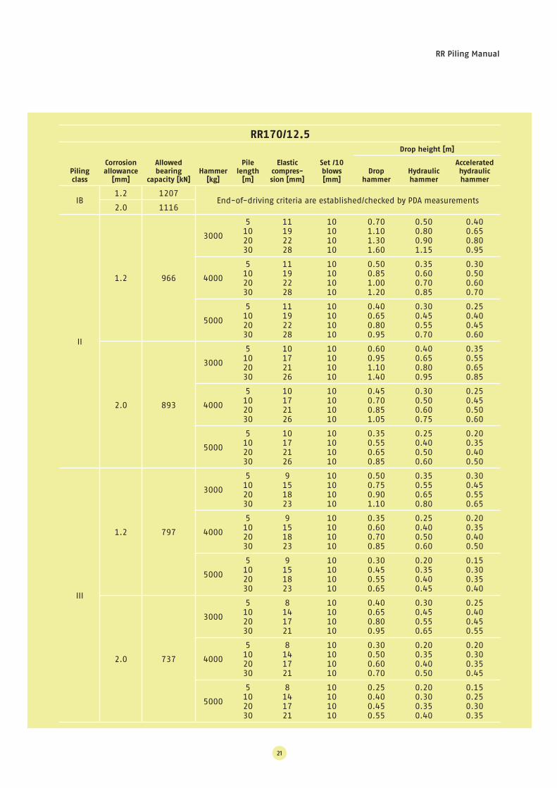
RR170/12.5
Piling
class
Corrosion
allowance
[mm]
Allowed
bearing
capacity [kN]
Hammer
[kg]
Pile
length
[m]
Elastic
compres-
sion [mm]
Set /10
blows
[mm]
Drop height [m]
Drop
hammer
Hydraulic
hammer
Accelerated
hydraulic
hammer
IB1.2 1207
End-of-driving criteria are established/checked by PDA measurements2.0 1116
II
1.2 966
3000
5102030
11192228
10101010
0.701.101.301.60
0.500.800.901.15
0.400.650.800.95
4000
5102030
11192228
10101010
0.500.851.001.20
0.350.600.700.85
0.300.500.600.70
5000
5102030
11192228
10101010
0.400.650.800.95
0.300.450.550.70
0.250.400.450.60
2.0 893
3000
5102030
10172126
10101010
0.600.951.101.40
0.400.650.800.95
0.350.550.650.85
4000
5102030
10172126
10101010
0.450.700.851.05
0.300.500.600.75
0.250.450.500.60
5000
5102030
10172126
10101010
0.350.550.650.85
0.250.400.500.60
0.200.350.400.50
III
1.2 797
3000
5102030
9151823
10101010
0.500.750.901.10
0.350.550.650.80
0.300.450.550.65
4000
5102030
9151823
10101010
0.350.600.700.85
0.250.400.500.60
0.200.350.400.50
5000
5102030
9151823
10101010
0.300.450.550.65
0.200.350.400.45
0.150.300.350.40
2.0 737
3000
5102030
8141721
10101010
0.400.650.800.95
0.300.450.550.65
0.250.400.450.55
4000
5102030
8141721
10101010
0.300.500.600.70
0.200.350.400.50
0.200.300.350.45
5000
5102030
8141721
10101010
0.250.400.450.55
0.200.300.350.40
0.150.250.300.35
22
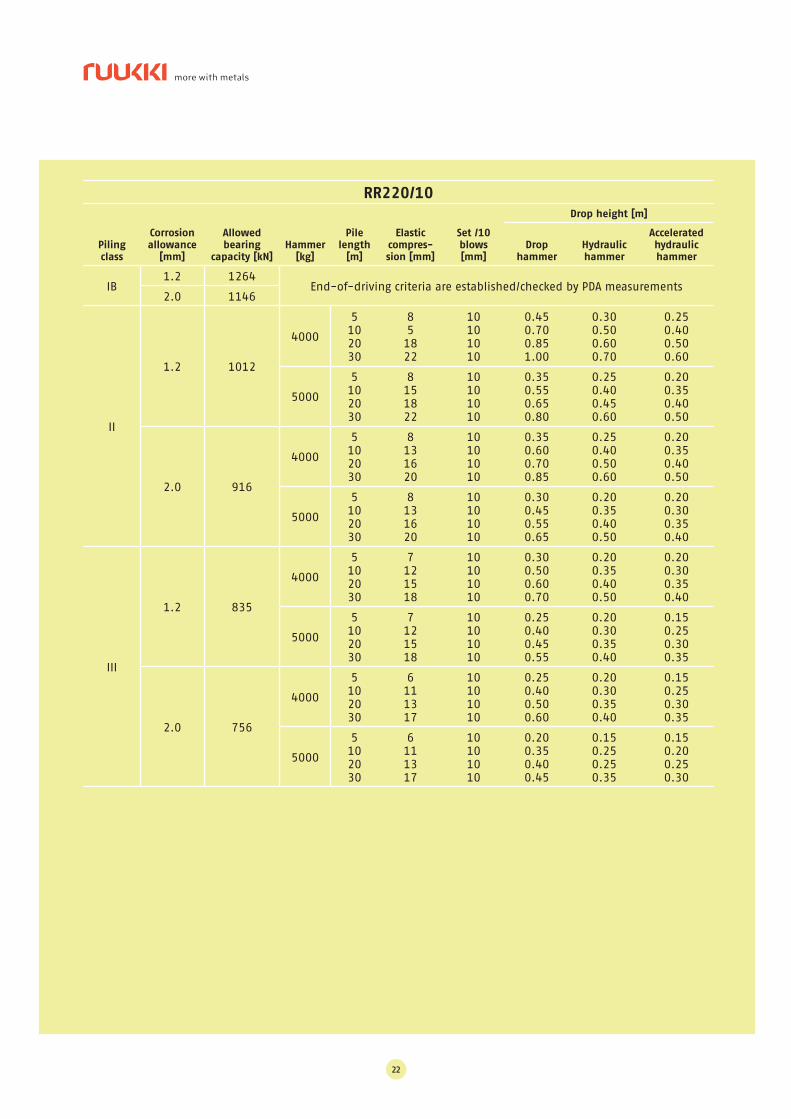
RR220/10
Piling
class
Corrosion
allowance
[mm]
Allowed
bearing
capacity [kN]
Hammer
[kg]
Pile
length
[m]
Elastic
compres-
sion [mm]
Set /10
blows
[mm]
Drop height [m]
Drop
hammer
Hydraulic
hammer
Accelerated
hydraulic
hammer
IB1.2 1264
End-of-driving criteria are established/checked by PDA measurements2.0 1146
II
1.2 1012
4000
5102030
851822
10101010
0.450.700.851.00
0.300.500.600.70
0.250.400.500.60
5000
5102030
8151822
10101010
0.350.550.650.80
0.250.400.450.60
0.200.350.400.50
2.0 916
4000
5102030
8131620
10101010
0.350.600.700.85
0.250.400.500.60
0.200.350.400.50
5000
5102030
8131620
10101010
0.300.450.550.65
0.200.350.400.50
0.200.300.350.40
III
1.2 835
4000
5102030
7121518
10101010
0.300.500.600.70
0.200.350.400.50
0.200.300.350.40
5000
5102030
7121518
10101010
0.250.400.450.55
0.200.300.350.40
0.150.250.300.35
2.0 756
4000
5102030
6111317
10101010
0.250.400.500.60
0.200.300.350.40
0.150.250.300.35
5000
5102030
6111317
10101010
0.200.350.400.45
0.150.250.250.35
0.150.200.250.30
RR Piling Manual
23
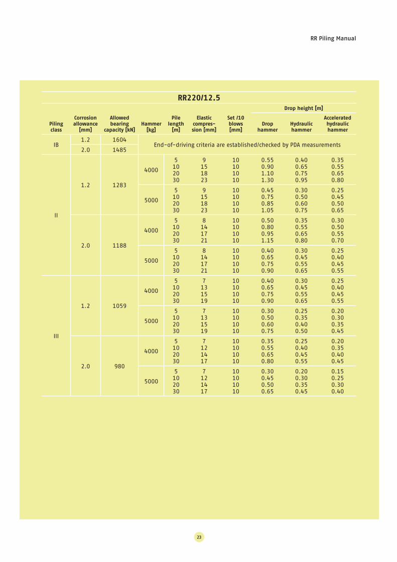
RR220/12.5
Piling
class
Corrosion
allowance
[mm]
Allowed
bearing
capacity [kN]
Hammer
[kg]
Pile
length
[m]
Elastic
compres-
sion [mm]
Set /10
blows
[mm]
Drop height [m]
Drop
hammer
Hydraulic
hammer
Accelerated
hydraulic
hammer
IB1.2 1604
End-of-driving criteria are established/checked by PDA measurements2.0 1485
II
1.2 1283
4000
5102030
9151823
10101010
0.550.901.101.30
0.400.650.750.95
0.350.550.650.80
5000
5102030
9151823
10101010
0.450.750.851.05
0.300.500.600.75
0.250.450.500.65
2.0 1188
4000
5102030
8141721
10101010
0.500.800.951.15
0.350.550.650.80
0.300.500.550.70
5000
5102030
8141721
10101010
0.400.650.750.90
0.300.450.550.65
0.250.400.450.55
III
1.2 1059
4000
5102030
7131519
10101010
0.400.650.750.90
0.300.450.550.65
0.250.400.450.55
5000
5102030
7131519
10101010
0.300.500.600.75
0.250.350.400.50
0.200.300.350.45
2.0 980
4000
5102030
7121417
10101010
0.350.550.650.80
0.250.400.450.55
0.200.350.400.45
5000
5102030
7121417
10101010
0.300.450.500.65
0.200.300.350.45
0.150.250.300.40

Rautaruukki Oyj Harvialantie 420, FI-13300 Hämeenlinna, Finland +358 20 591 26
+358 2o 592 5873 www.ruukki.com
Copyright © 2005 Rautaruukki Corporation. All rights reserved. Ruukki and More With Metals are trademarks of Rautaruukki
Corporation.
Ruukki is a metal expert you can rely on all the way, whenever you need metal based materials,
components, systems or total solutions. We constantly develop our product range and operating
models to match your needs.
CFI 0
3.0
01EN
/07.2
005