router-shelf redundancy for the cisco as5800 · router-shelf redundancy for the cisco as5800 ......
TRANSCRIPT
Router-Shelf Redundancy for the Cisco AS5800
This document describes router-shelf redundancy for the Cisco AS5800 universal access server. It includesthe following sections:
• Finding Feature Information, page 1
• Feature Overview, page 1
• Prerequisites, page 4
• Configuration Examples, page 4
• Additional References, page 7
• Feature Information for Router-Shelf Redundancy for the Cisco AS5800, page 8
• Glossary, page 8
Finding Feature InformationYour software release may not support all the features documented in this module. For the latest caveats andfeature information, see Bug Search Tool and the release notes for your platform and software release. Tofind information about the features documented in this module, and to see a list of the releases in which eachfeature is supported, see the feature information table at the end of this module.
Use Cisco Feature Navigator to find information about platform support and Cisco software image support.To access Cisco Feature Navigator, go to www.cisco.com/go/cfn. An account on Cisco.com is not required.
Feature OverviewThis feature provides router-shelf redundancy by using a second router shelf that automatically takes over theother shelf’s dial-shelf cards (DSCs) if it appears that the other router shelf has died. Failover is disruptive inthat there is no attempt to maintain calls that were established on the failing router shelf; the DSCs controlledby the failing router shelf are restarted under control of the backup router shelf and hence become availableagain.
Two router shelves are connected to the same DSC (as in split mode), but with only one router shelf activeat a time. Both router shelves are configured for normal mode as opposed to split mode. Each router shelfcontains the same configuration, being whatever configuration is appropriate for the full set of DSCs. The
Interface and Hardware Component Configuration Guide, Cisco IOS Release 15M&T 1
active router shelf controls all the DSCs, while the other router shelf functions purely as a backup. If the activerouter shelf fails, all DSCs restart under the control of the backup router shelf, which then functions as theactive router shelf.
Only one router shelf has control of the DSCs at a time; the other keeps trying to take control but is unableto, and does not interfere with operation of the active router shelf. If, however, the active router shelf crashes,then it relinquishes control of all DSCs to the other router shelf, which restarts the DSCs and commencesnormal operation. If the crashed router shelf recovers or is restarted, it does not take back control of the DSCs,but instead functions as a backup, and takes control again only if the other router shelf fails.
External interfaces cannot share the same IP address between the two routers shelves, to prevent duplicate IPaddress errors.
Triggers for a failover to occur are those that lead to a hub switchover. The main trigger is loss of the linkbetween the active router shelf (the one with control of the cards) and its DSC as detected by link monitoringon the DSC . Any router-shelf failures that do not result in this link going down do not cause failover--forexample, the active router’s egress interface going down does not trigger failover. Conversely, any temporaryloss of the link between the active router and a DSC does cause failover, even if the router shelf itself doesnot crash and connectivity is quickly reestablished--for example, if the BIC cable is knocked out and thenquickly replaced. In addition, failover is triggered if a DSC connected to the active router shelf goes downand fails to recover within 90 seconds.
Note
Additional Considerations
System ControllerWhen a system controller is used with a redundant router shelf, router-shelf failover should look like a singlerouter shelf going down briefly and then recovering. With the current system-controller code, this does notwork. The Cisco SC3640 expects only a single router shelf to be configured with any given shelf ID. To getaround this, a router in backup mode must be prevented from sending Session Definition Protocol (SDP)packets to the Cisco SC3640. In addition, the SDP packets sent by the router shelves to the Cisco SC3640currently include a field identifying the MAC address of the sending router. The Cisco SC3640 stores thisMAC address and, if it subsequently receives another SDP packet containing the same shelf ID but not thesame MAC address, it concludes that multiple routers are configured with the same shelf ID and treats thisas an error. This is precisely the situation after a failover, when the backup router shelf starts sending SDPpackets with the same shelf ID but different MAC address.
To get around this, you must configure a failover group code--an integer that identifies a redundant pair ofrouter shelves. Each member of the pair must be configured with the same group code. When failover modeis enabled, this group code is sent in place of the router MAC address. These changes are all made to thesystem-controller code that runs on the router shelf itself, rather than on the Cisco SC3640.
Load SharingThere is no load sharing between the two routers shelves--no calls can go through the backup router shelf.One disadvantage of this is that you cannot split the load between the routers to reduce the number of callsthat are lost when a router crashes. There are, however, also some advantages: with load sharing, you mustensure that each router can support the entire dial shelf, since upon failure of a router shelf the surviving router
Interface and Hardware Component Configuration Guide, Cisco IOS Release 15M&T2
Router-Shelf Redundancy for the Cisco AS5800Additional Considerations
shelf owns all the dial-shelf resources, and therefore has a sudden change in the amount of traffic it is supporting.If care had not been taken to test under failover conditions, at full load the surviving router shelf might beoverwhelmed, and perhaps provide degraded service. With a redundant router shelf instead acting purely asa standby, provided that the backup router shelf is the same model as the active router shelf, the load isunchanged after switchover--so no change is expected to the router-shelf performance.
Having a single router shelf active at a time is simpler, and makes it easier to support failover when dealingwith external servers such as signaling controllers for SS7, RPMS server, and system controllers.
Hitless RedundancyWhen router-shelf failover occurs, all calls associated with the failed router shelf are lost. To maintain callsthrough router-shelf failure requires mirroring call state and fast failure detection. This shelf-redundancyfeature ensures only that resources (particularly trunk lines) do not remain unusable while the router shelf thatwas controlling them is down.
Network ManagementMinimal Simple Network Management Protocol (SNMP) support is provided--a trap is issued when failoveroccurs, and SNMP variables indicate whether a router shelf is active or on standby. An existingMIB--CISCO-C8500-REDUNDANCY-MIB--defines a suitable trap for issuing on failover.
BenefitsWhen an active router shelf in a Cisco AS5800 loses communication with its DSC, a backup router shelf canbe invoked to automatically take over DSCs controlled by the lost router shelf. This backup method, calledredundancy, is provided on the Cisco AS5800 to prevent a single point of failure, subsequent downtime, anduser intervention to resolve unrecoverable hardware faults.
Restrictions
Router Shelves
Two router shelves of the same model and configuration must be available for this feature to operate.
External Servers
Although some of the failover functionality exists in the existing code base, ensure that the various externalservers that can run with the Cisco AS5800 still function when redundant router shelves are used. The serversof concern at the moment are RPMS, SS7, and System Controller; the first two are discussed below:
• Resource pool management server (RPMS). For Resource PoolManagement (RPM) to work, the resourcepool manager server (RPMS) must be configured with the same information for both router shelves.
• Signaling System 7 (SS7). In an SS7 setup, the call signaling comes through an external Cisco SC2200unit rather than directly from the switch over the trunk line (as for CAS and ISDN). For call signalingto work after failover, both router shelves must be connected to the Cisco SC2200 using the SS7Redundant Link Manager (RLM) feature, which was intended to provide redundant links between asingle router shelf and the signaling controller. RLM links must be configured from both the active and
Interface and Hardware Component Configuration Guide, Cisco IOS Release 15M&T 3
Router-Shelf Redundancy for the Cisco AS5800Benefits
standby router shelves--the change of router shelves will look like a change from one redundant link toanother.
Related Features and Technologies
RSC Handover Redundancy
The Router Shelf Controller Handover Redundancy feature that is available on the Cisco AS5850 is similarto Router Shelf Redundancy on the Cisco AS5800.
Prerequisites• Ensure that your network is up and running.
• Test each router shelf to verify connectivity.
Configuration Examples
Configuring the Cisco AS5800 for Shelf Redundancy
SUMMARY STEPS
1. Router(config)# redundancy2. Router(config-red)# failover group-number group-code
DETAILED STEPS
PurposeCommand or Action
Enters configuration-redundancy mode.Router(config)# redundancyStep 1
Configures router-shelf failover.Router(config-red)# failovergroup-number group-code
Step 2
Use the same group-code argument for both routers. This codeis used when the system controller is used and it identifies thetwo routers as effectively representing the same set of dial-shelfresources.
Note
What to Do Next
Connect to each router shelf in turn and enter these commands. Treat router shelves as if they are connectedas a split dial-shelf configuration.
Interface and Hardware Component Configuration Guide, Cisco IOS Release 15M&T4
Router-Shelf Redundancy for the Cisco AS5800Related Features and Technologies
This configuration by itself is not enough for successful failover to occur. Because there is no automaticsynchronization of configuration between router shelves, you must configure each router shelf separately.Typically the two router shelves, active and backup, must have the same configuration except for the IPaddress on egress interfaces.
Note
Since configuration is error prone, test the backup router shelf’s configuration to ensure that errors are notdiscovered only when the active router shelf fails in a production environment.
Note
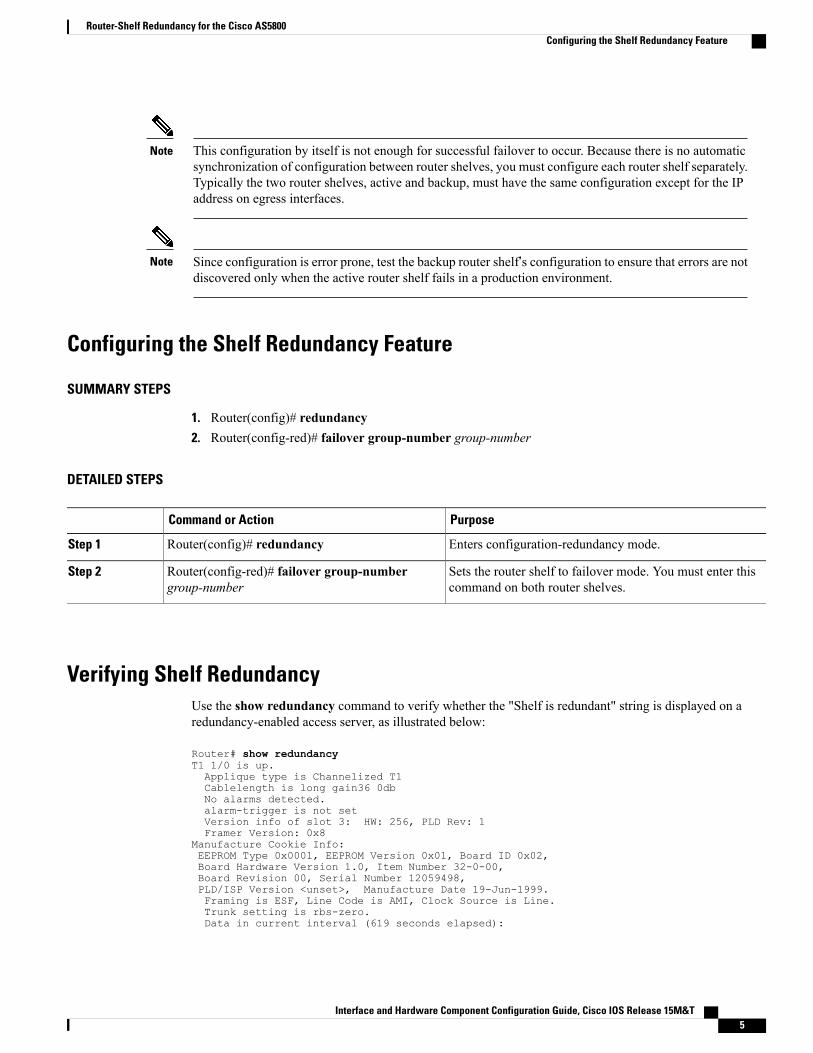
Configuring the Shelf Redundancy Feature
SUMMARY STEPS
1. Router(config)# redundancy2. Router(config-red)# failover group-number group-number
DETAILED STEPS
PurposeCommand or Action
Enters configuration-redundancy mode.Router(config)# redundancyStep 1
Sets the router shelf to failover mode. You must enter thiscommand on both router shelves.
Router(config-red)# failover group-numbergroup-number
Step 2
Verifying Shelf RedundancyUse the show redundancy command to verify whether the "Shelf is redundant" string is displayed on aredundancy-enabled access server, as illustrated below:
Router# show redundancyT1 1/0 is up.Applique type is Channelized T1Cablelength is long gain36 0dbNo alarms detected.alarm-trigger is not setVersion info of slot 3: HW: 256, PLD Rev: 1Framer Version: 0x8
Manufacture Cookie Info:EEPROM Type 0x0001, EEPROM Version 0x01, Board ID 0x02,Board Hardware Version 1.0, Item Number 32-0-00,Board Revision 00, Serial Number 12059498,PLD/ISP Version <unset>, Manufacture Date 19-Jun-1999.Framing is ESF, Line Code is AMI, Clock Source is Line.Trunk setting is rbs-zero.Data in current interval (619 seconds elapsed):
Interface and Hardware Component Configuration Guide, Cisco IOS Release 15M&T 5
Router-Shelf Redundancy for the Cisco AS5800Configuring the Shelf Redundancy Feature
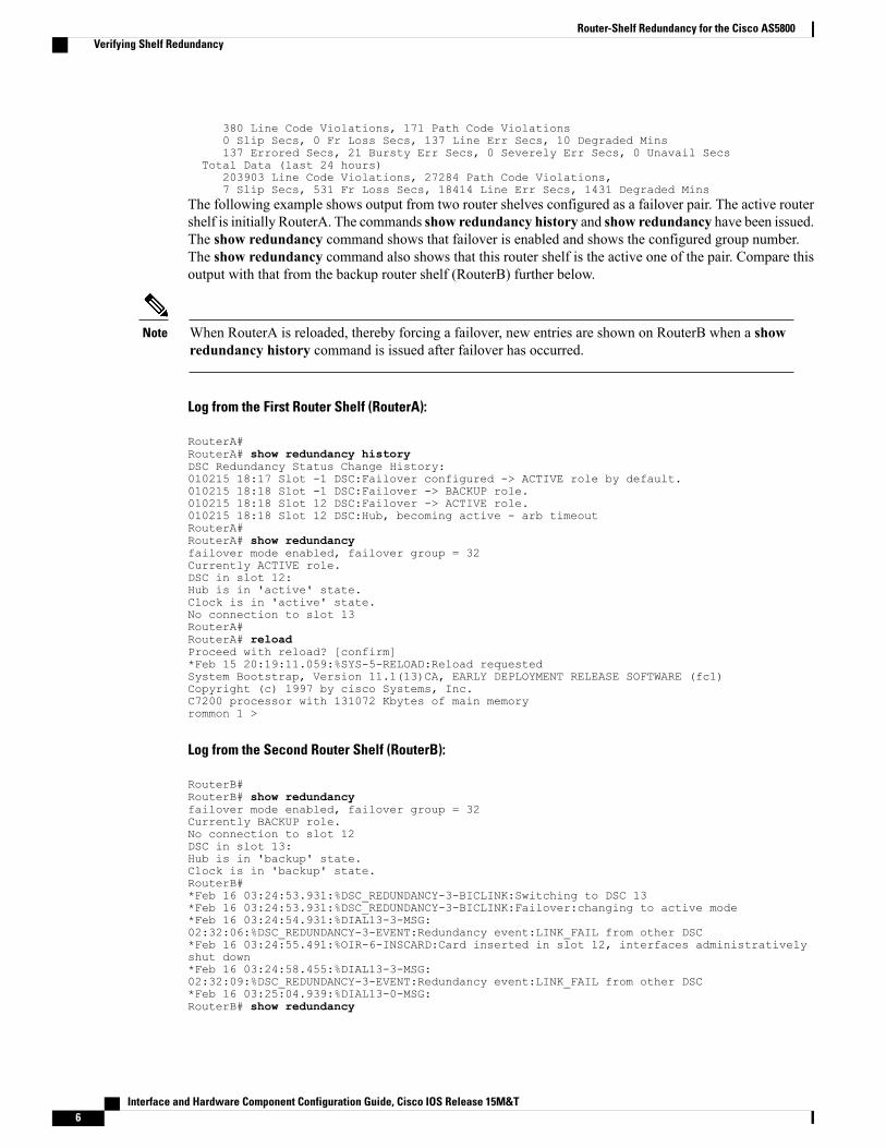
380 Line Code Violations, 171 Path Code Violations0 Slip Secs, 0 Fr Loss Secs, 137 Line Err Secs, 10 Degraded Mins137 Errored Secs, 21 Bursty Err Secs, 0 Severely Err Secs, 0 Unavail Secs
Total Data (last 24 hours)203903 Line Code Violations, 27284 Path Code Violations,7 Slip Secs, 531 Fr Loss Secs, 18414 Line Err Secs, 1431 Degraded Mins
The following example shows output from two router shelves configured as a failover pair. The active routershelf is initially RouterA. The commands show redundancy history and show redundancy have been issued.The show redundancy command shows that failover is enabled and shows the configured group number.The show redundancy command also shows that this router shelf is the active one of the pair. Compare thisoutput with that from the backup router shelf (RouterB) further below.
When RouterA is reloaded, thereby forcing a failover, new entries are shown on RouterB when a showredundancy history command is issued after failover has occurred.
Note
Log from the First Router Shelf (RouterA):
RouterA#RouterA# show redundancy historyDSC Redundancy Status Change History:010215 18:17 Slot -1 DSC:Failover configured -> ACTIVE role by default.010215 18:18 Slot -1 DSC:Failover -> BACKUP role.010215 18:18 Slot 12 DSC:Failover -> ACTIVE role.010215 18:18 Slot 12 DSC:Hub, becoming active - arb timeoutRouterA#RouterA# show redundancyfailover mode enabled, failover group = 32Currently ACTIVE role.DSC in slot 12:Hub is in 'active' state.Clock is in 'active' state.No connection to slot 13RouterA#RouterA# reloadProceed with reload? [confirm]*Feb 15 20:19:11.059:%SYS-5-RELOAD:Reload requestedSystem Bootstrap, Version 11.1(13)CA, EARLY DEPLOYMENT RELEASE SOFTWARE (fc1)Copyright (c) 1997 by cisco Systems, Inc.C7200 processor with 131072 Kbytes of main memoryrommon 1 >
Log from the Second Router Shelf (RouterB):
RouterB#RouterB# show redundancyfailover mode enabled, failover group = 32Currently BACKUP role.No connection to slot 12DSC in slot 13:Hub is in 'backup' state.Clock is in 'backup' state.RouterB#*Feb 16 03:24:53.931:%DSC_REDUNDANCY-3-BICLINK:Switching to DSC 13*Feb 16 03:24:53.931:%DSC_REDUNDANCY-3-BICLINK:Failover:changing to active mode*Feb 16 03:24:54.931:%DIAL13-3-MSG:02:32:06:%DSC_REDUNDANCY-3-EVENT:Redundancy event:LINK_FAIL from other DSC*Feb 16 03:24:55.491:%OIR-6-INSCARD:Card inserted in slot 12, interfaces administrativelyshut down*Feb 16 03:24:58.455:%DIAL13-3-MSG:02:32:09:%DSC_REDUNDANCY-3-EVENT:Redundancy event:LINK_FAIL from other DSC*Feb 16 03:25:04.939:%DIAL13-0-MSG:RouterB# show redundancy
Interface and Hardware Component Configuration Guide, Cisco IOS Release 15M&T6
Router-Shelf Redundancy for the Cisco AS5800Verifying Shelf Redundancy
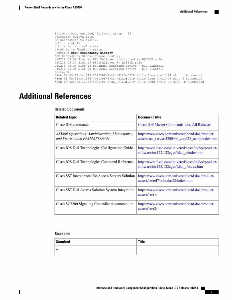
failover mode enabled, failover group = 32Currently ACTIVE role.No connection to slot 12DSC in slot 13:Hub is in 'active' state.Clock is in 'backup' state.RouterB# show redundancy historyDSC Redundancy Status Change History:010216 03:09 Slot -1 DSC:Failover configured -> BACKUP role.010216 03:24 Slot 13 DSC:Failover -> ACTIVE role.010216 03:24 Slot 13 DSC:Hub, becoming active - D12 linkfail010216 03:24 Slot 13 DSC:Hub, becoming active - D12 linkfailRouterB#*Feb 16 03:26:14.079:%DSIPPF-5-DS_HELLO:DSIP Hello from shelf 47 slot 1 Succeeded*Feb 16 03:26:14.255:%DSIPPF-5-DS_HELLO:DSIP Hello from shelf 47 slot 3 Succeeded*Feb 16 03:26:14.979:%DSIPPF-5-DS_HELLO:DSIP Hello from shelf 47 slot 10 Succeeded
Additional ReferencesRelated Documents
Document TitleRelated Topic
Cisco IOS Master Commands List, All ReleasesCisco IOS commands
http://www.cisco.com/univercd/cc/td/doc/product/access/acs_serv/as5800/sw_conf/58_oamp/index.htm
AS5800 Operations, Administration, Maintenance,and Provisioning (OAM&P) Guide
http://www.cisco.com/univercd/cc/cc/td/doc/product/software/ios122/122cgcr/fdial_c/index.htm
Cisco IOS Dial Technologies Configuration Guide
http://www.cisco.com/univercd/cc/cc/td/doc/product/software/ios122/122cgcr/fdial_r/index.htm
Cisco IOS Dial Technologies Command Reference
http://www.cisco.com/univercd/cc/td/doc/product/access/sc/rel7/soln/das22/index.htm
Cisco SS7 Interconnect for Access Servers Solution
http://www.cisco.com/univercd/cc/td/doc/product/access/sc/r1/
Cisco SS7 Dial Access Solution System Integration
http://www.cisco.com/univercd/cc/td/doc/product/access/sc/r2/
Cisco SC2200 Signaling Controller documentation
Standards
TitleStandard
--
Interface and Hardware Component Configuration Guide, Cisco IOS Release 15M&T 7
Router-Shelf Redundancy for the Cisco AS5800Additional References
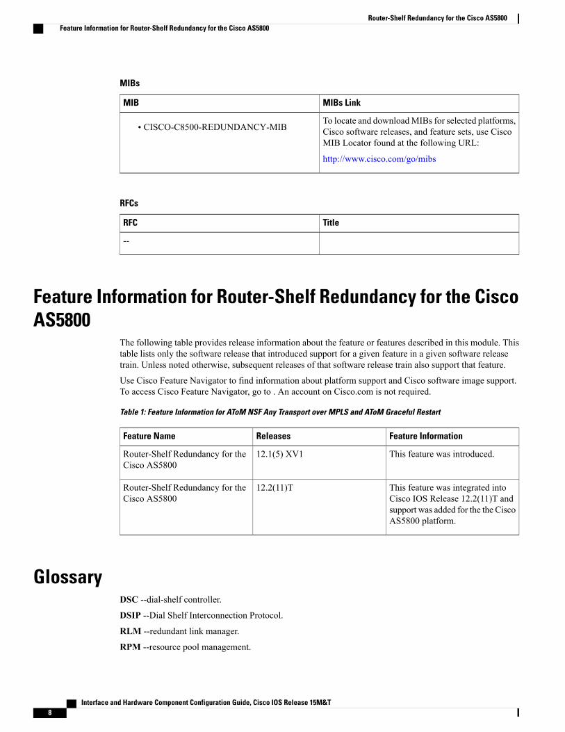
MIBs
MIBs LinkMIB
To locate and downloadMIBs for selected platforms,Cisco software releases, and feature sets, use CiscoMIB Locator found at the following URL:
http://www.cisco.com/go/mibs
• CISCO-C8500-REDUNDANCY-MIB
RFCs
TitleRFC
--
Feature Information for Router-Shelf Redundancy for the CiscoAS5800
The following table provides release information about the feature or features described in this module. Thistable lists only the software release that introduced support for a given feature in a given software releasetrain. Unless noted otherwise, subsequent releases of that software release train also support that feature.
Use Cisco Feature Navigator to find information about platform support and Cisco software image support.To access Cisco Feature Navigator, go to . An account on Cisco.com is not required.
Table 1: Feature Information for AToM NSF Any Transport over MPLS and AToM Graceful Restart
Feature InformationReleasesFeature Name
This feature was introduced.12.1(5) XV1Router-Shelf Redundancy for theCisco AS5800
This feature was integrated intoCisco IOS Release 12.2(11)T andsupport was added for the the CiscoAS5800 platform.
12.2(11)TRouter-Shelf Redundancy for theCisco AS5800
GlossaryDSC --dial-shelf controller.
DSIP --Dial Shelf Interconnection Protocol.
RLM --redundant link manager.
RPM --resource pool management.
Interface and Hardware Component Configuration Guide, Cisco IOS Release 15M&T8
Router-Shelf Redundancy for the Cisco AS5800Feature Information for Router-Shelf Redundancy for the Cisco AS5800
RPMS --resource pool manager server.
SDP --Session Definition Protocol.
SNMP --Simple Network Management Protocol.
SS7 --Signaling System 7.
Interface and Hardware Component Configuration Guide, Cisco IOS Release 15M&T 9
Router-Shelf Redundancy for the Cisco AS5800Glossary
Interface and Hardware Component Configuration Guide, Cisco IOS Release 15M&T10
Router-Shelf Redundancy for the Cisco AS5800Glossary