route 205/lammers road interchange 205/lammers road interchange ... 2.1 design standards and ... the...
TRANSCRIPT

Route 205/Lammers Road Interchange 10-SJ- 205 PM 2.6/R5.1
EA 10-0H9100 May 06, 2010
Preliminary Drainage Report Route 205/Lammers Road Interchange
W ELEVENTH ST
W SCHULTE RD
HANS
EN R
D
S LA
MM
ERS
RD
MO
UNTA
IN H
OUS
E PK
WY
VON SOSTEN RD
W GRANT LINE RD
REEV
ES R
D
SAN
JOSE
RD
S LA
MM
ERS
RD
NAG
LEE
RD
S CO
RRAL
HO
LLO
W R
DW BETHANY RD
W MIDDLE RD
ProjectLocation
Construct Interchange on Interstate 205 In San Joaquin County, In and Near City of Tracy From Hansen Road OC To Grant Line Road UC
Prepared by: Rajappan & Meyer Consulting Engineers, Inc.
1038 LEIGH AVE, SUITE 100 SAN JOSE, CA-95126
PH: (408)-280-2772


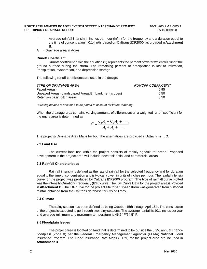
ROUTE 205/LAMMERS ROAD/ELEVENTH STREET INTERCHANGE PROJECT 10-SJ-205 PM 2.6/R5.1 PRELMINARY DRAINAGE REPORT EA 10-0H9100
May 2010
i
TABLE OF CONTENTS 1. DESCRIPTION OF THE PROJECT ....................................................1 2. HYDROLOGY ......................................................................................1
2.1 Design Standards and Criteria ..............................................................................1 2.2 Land Use .....................................................................................................................2 2.3 Rainfall Characteristics .............................................................................................2 2.4 Climate ........................................................................................................................2 2.5 Floodplain Issues .......................................................................................................2 2.6 Ground Water Table ..................................................................................................3
3. HYDRAULICS......................................................................................3
3.1 Existing Facilities .......................................................................................................3 3.2 Design Standards and Criteria .................................................................................4 3.3 Methodology ...............................................................................................................4 3.4 Proposed Drainage System ......................................................................................5
4. OTHER AGENCIES.............................................................................9
4.1 Regional Water Quality Control Board (RWQCB) .................................................9 4.2 City of Tracy................................................................................................................9 4.3 San Joaquin County ..................................................................................................9 4.4 West Side Irrigation District (WSID) ........................................................................9
5. WATER QUALITY .............................................................................10 6. SPECIAL CONSIDERATIONS..........................................................10 7. SOIL CLASSIFICATION.................................................................... 10 8. ATTACHMENTS................................................................................10 A. Project Location Map
B. IDF Curve Data C. Drainage Area Map D. FIRM Maps


ROUTE 205/LAMMERS ROAD/ELEVENTH STREET INTERCHANGE PROJECT 10-SJ-205 PM 2.6/R5.1 PRELMINARY DRAINAGE REPORT EA 10-0H9100
1 May 2010
1. DESCRIPTION OF THE PROJECT
The purpose of the project is to provide additional connectivity to Route 205 to serve the increase in forecasted traffic demand at surrounding interchanges and to improve regional mobility by connecting a planned regional arterial road with Route 205. The project consists of a new interchange at Lammers Road on Route 205 between Eleventh Street and Grant Line Road interchanges in northwest Tracy in San Joaquin County. The proposed improvements include the following components in the two Alternatives considered in this project: Alternative 1 - This alternative consists of construction of a Type L-2 spread diamond interchange at Lammers Road and auxiliary lanes in both eastbound and westbound directions of Route 205 between Lammers Road and Grant Line Road interchanges. Alternative 5A - This alternative consists of construction of a Type L-7 partial cloverleaf interchange to replace the existing Eleventh Street interchange, construction of an auxiliary lane in the westbound direction from Eleventh Street to Grant Line Road and a 1,000’ long acceleration lane in the eastbound direction. The project is anticipated to be funded by a variety of sources including the San Joaquin County Measure K Renewal sales tax program, Regional Surface Transportation Program, and local Public Facility Fees generated by ongoing development and direct developer contribution. The project is located in the City of Tracy in San Joaquin County. The location map is provided in Attachment A.
2. HYDROLOGY
2.1 Design Standards and Criteria Design Storm Design storm is defined as the particular storm event of a particular duration that contributes runoff for which drainage facilities are designed to handle. In accordance with HDM Table 831.3, a 25-year design storm is used for I-205 and a 10-year storm is used for Lammers Road (Alt. 1), Eleventh Street (Alt. 5A) and the interchange ramps. Two consecutive 10-year frequency storms of 24 hour duration each were selected as the design storm event for retention basins as per Hydraulic Design Guide (Central Region), a supplement to Highway Design Manual. Design Discharge Design runoff for the design storm event was determined using Rational Method. The following are the assumptions made: 1. The rainfall is of equal intensity over the entire watershed. 2. The peak flow occurs when the entire watershed is contributing to the flow. The formula used to calculate the discharge is
CiAQ = (1)
where, Q = Design discharge in cubic feet per second. C = Weighted Runoff Coefficient for the entire watershed.
ROUTE 205/LAMMERS ROAD/ELEVENTH STREET INTERCHANGE PROJECT 10-SJ-205 PM 2.6/R5.1 PRELMINARY DRAINAGE REPORT EA 10-0H9100
2 May 2010
i = Average rainfall intensity in inches per hour (in/hr) for the frequency and a duration equal to the time of concentration = 0.14 in/hr based on Caltrans’ IDF2000, as provided in Attachment B.
A = Drainage area in Acres. Runoff Coefficient Runoff coefficient “C” in the equation (1) represents the percent of water which will runoff the ground surface during the storm. The remaining percent of precipitation is lost to infiltration, transpiration, evaporation, and depression storage. The following runoff coefficients are used in the design: TYPE OF DRAINAGE AREA RUNOFF COEFFICEINT Paved Areas* 0.95 Unpaved Areas (Landscaped Areas/Embankment slopes) 0.50 Retention basin/ditch areas 0.50 *Existing median is assumed to be paved to account for future widening. When the drainage area contains varying amounts of different cover, a weighted runoff coefficient for the entire area is determined as
............
21
2211
++++
=AA
ACACC
The project’s Drainage Area Maps for both the alternatives are provided in Attachment C.
2.2 Land Use The current land use within the project consists of mainly agricultural areas. Proposed development in the project area will include new residential and commercial areas.
2.3 Rainfall Characteristics Rainfall intensity is defined as the rate of rainfall for the selected frequency and for duration equal to the time of concentration and is typically given in units of inches per hour. The rainfall intensity curve for the project was produced by Caltrans IDF2000 program. The type of rainfall curve plotted was the Intensity-Duration-Frequency (IDF) curve. The IDF Curve Data for the project area is provided in Attachment B. The IDF curve for the project site for a 10 year storm was generated from historical rainfall obtained from the Caltrans database for City of Tracy.
2.4 Climate
The rainy season has been defined as being October 15th through April 15th. The construction of the project is expected to go through two rainy seasons. The average rainfall is 10.1 inches per year and average minimum and maximum temperature is 46.6° F/74.5° F.
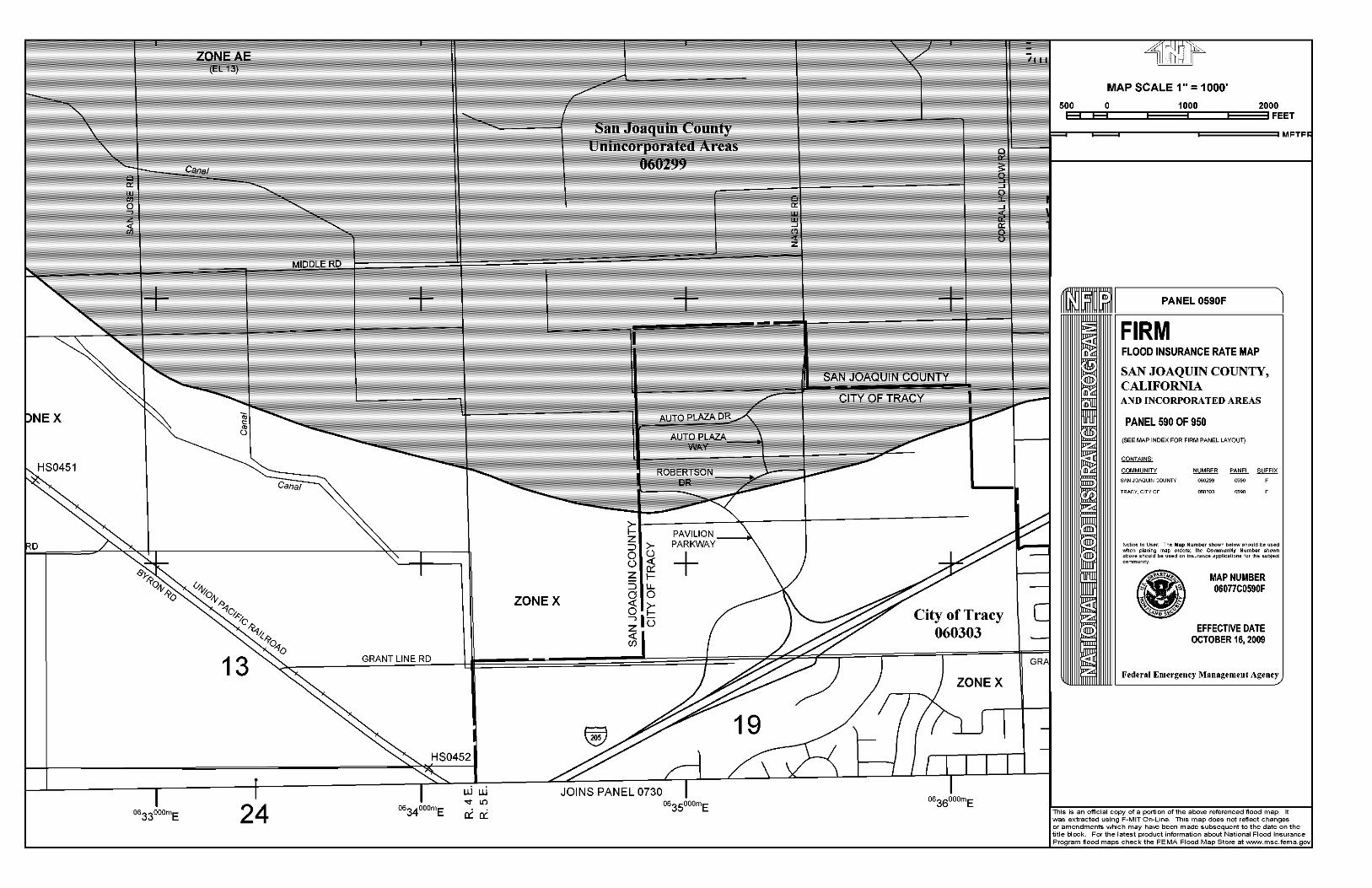
2.5 Floodplain Issues
The project area is located on land that is determined to be outside the 0.2% annual chance floodplain (Zone X) per the Federal Emergency Management Agency’s (FEMA) National Flood Insurance Program. The Flood Insurance Rate Maps (FIRM) for the project area are included in Attachment D.

ROUTE 205/LAMMERS ROAD/ELEVENTH STREET INTERCHANGE PROJECT 10-SJ-205 PM 2.6/R5.1 PRELMINARY DRAINAGE REPORT EA 10-0H9100
3 May 2010
2.6 Ground Water Table
From the Preliminary Geotechnical Information (Foundation Type Selection) by Parikh Consultants, the Ground water table (GWT) at Janney OH (W. Byron Rd.) was found to be at approximate elevations of 26 feet and 25 feet per the as-built Log of Test Borings (LOTB). Site-specific groundwater conditions within the project limits should be verified during the PS&E phase.
3. HYDRAULICS
3.1 Existing Facilities
The existing runoff from Route 205 is conveyed as sheet flow across the roadway side slopes and drain into the ditches along the toe of slopes of the freeway. There are also sections of freeway with dikes and downdrains. There are inlets and cross drains from the median to collect and convey the runoff from the median to the side ditches. The existing downdrains and cross-culverts are outletted to short dissipation ditches, and allowed to sheet flow out of the right-of-way. The following are the existing cross drainage culverts within the project limits for Alternative 1;
Location Culvert Description Proposed Improvement
“G” Sta 199+00 18”x 88’ RCP
Drains the median to WB I-205 side ditches
Extend to accommodate WB auxiliary lane
“G” Sta 206+00 24”x 174’ RCP
Cross drainage culvert across I-205
Extend to accommodate across EB and WB ramps
“G” Sta 213+00 18”x 86’ RCP
Drains the median to WB I-205 side ditches
No improvements needed
“G” Sta 220+00 18”x 90’ RCP
Drains the median to EB and WB I-205 side ditches
No improvements needed
“G” Sta 226+80 18”x 88’ RCP
Drains the median to EB and WB I-205 side ditches
No improvements needed
“G” Sta 249+25 24”x 350’ RCP
WSID culvert No improvements needed
The following are the existing cross drainage culverts within the project limits for Alternative 5A;
Location Culvert Description Proposed Improvement
“A2-1” Sta 151+50 29”x 18” CMPA
Cross drainage culvert across I-205
No improvements needed
“B1” Sta 160+00 18”x 72’ CMP Drains the median to EB I-205 side ditches
No improvements needed
“C1” Sta 160+00 18”x 12’ CMP
Drains the median to WB I-205 side ditches
Extend to accommodate EB and WB auxiliary lanes
“B1” Sta 170+00 24”x 182’ RCP
Cross drainage culvert across I-205
No improvements needed
“G” Sta 178+70 18”x 88’ RCP
Drains the median to WB I-205 side ditches
No improvements needed

ROUTE 205/LAMMERS ROAD/ELEVENTH STREET INTERCHANGE PROJECT 10-SJ-205 PM 2.6/R5.1 PRELMINARY DRAINAGE REPORT EA 10-0H9100
4 May 2010
“G” Sta 187+00 24”x 184’ RCP
Cross drainage culvert across I-205
Extend to accommodate EB and WB auxiliary lanes
“G” Sta 192+00 24”x 172’ RCP
Cross drainage culvert across I-205
Extend to accommodate EB and WB ramps
“G” Sta 199+00 18”x 88’ RCP
Drains the median to WB I-205 side ditches
Extend to accommodate WB auxiliary lane
“G” Sta 206+00 24”x 174’ RCP
Cross drainage culvert across I-205
Extend to accommodate EB and WB loop ramps
“G” Sta 213+00 18”x 86’ RCP
Drains the median to WB I-205 side ditches
No improvements needed
“G” Sta 220+00 18”x 90’ RCP
Drains the median to EB and WB I-205 side ditches
Extend to accommodate EB auxiliary lane
“G” Sta 226+80 18”x 88’ RCP
Drains the median to EB and WB I-205 side ditches
Extend to accommodate EB auxiliary lane
“G” Sta 249+25 24”x 350’ RCP
WSID culvert No improvements needed
The direction of the existing watershed within the project limits is from southwest to northeast across the freeway through the existing cross drainage culverts. Cross drainage culverts are proposed across Lammers Road south of eastbound ramps to provide relief and not to disrupt the natural drainage. All the existing cross drainage culverts will be extended wherever the freeway is widened to accommodate ramps or auxiliary lanes in order to keep the existing watershed flow patterns intact. Existing culverts will be analyzed for capacity and condition in PS&E phase. If needed, more culverts will be added by Jack and Bore method across I-205 to conform to the current design standards.
3.2 Design Standards and Criteria Design Storm The design criterion for retention basins is to size the basins to contain the runoff generated by the design storm event. The following embankment side slope standards as per Topic 304 of HDM were considered for designing the basins.
1) The embankment slopes should be 4:1 2) In light grading where normal slopes catch in a distance less than 18 feet from the edge of the
shoulder, a uniform catch point, at least 18 feet from the edge of the shoulder, should be used.
3.3 Methodology Preliminary basin layouts were prepared using the available site aerial topography and proposed geometric layouts. The Storm runoff volume is calculated by,
QTFVR **= (2) Where, VR = Total runoff for the design event (ft3). Q = Discharge from equation (1) (ft3/s) F = Factor of Safety = 2 T = Rainfall Duration = 24 hours = 86,400 seconds From the layout plan, the top and bottom areas of the basins were determined. The volume of the storm runoff stored in the basin was calculated by,

ROUTE 205/LAMMERS ROAD/ELEVENTH STREET INTERCHANGE PROJECT 10-SJ-205 PM 2.6/R5.1 PRELMINARY DRAINAGE REPORT EA 10-0H9100
5 May 2010
DepthAA
V bottomtopS *
2
+= (3)
Where, VS = Capacity of the Basin i.e. volume of the storm runoff stored in the basin (ft3). Atop = Top area of the basin (ft2). Abottom = Bottom area of the basin (ft2). Depth = Design water depth of the basin (ft).
3.4 Proposed Drainage System There are no natural waterways within the project area and the project will not be allowed to connect to local storm drain systems. The storm runoff generated within the project area must be contained in a series of retention basins. A system of roadway drainage ditches, inlets and pipe culverts will be proposed to convey runoff from paved areas to the proposed retention basins. Existing cross culverts will be extended to meet the new roadway side slopes wherever necessary. The detailed drainage design will be developed during the PS&E phase, using all applicable Caltrans and District 10 design standards. On the I-205 mainline and interchange ramps, 4:1 embankment slopes and retaining walls with safety shaped concrete barriers are proposed. Storm water will sheet flow on 4:1 embankment slopes into the vegetated ditches. Runoff from all the impervious areas will be drained into the retention basins via underground drainage system. Drainage inlets and pipes will convey water from mainline along the eastbound on-ramp and auxiliary lanes wherever retaining walls are proposed. Lammers Road (Alternative 1) and Eleventh Street (Alternative 5A) will have curb and gutter and inlets at the outer roadway edges to collect and convey runoff. Detailed hydraulic analysis and design will be completed in PS&E phase. The required storage volume for the retention basins has been calculated based on equation (2). The project area within the State right of way (I-205 and Interchange) within the project limits was divided into several drainage areas, and the basins serving each area were sized to retain the corresponding volume of storm runoff generated by the drainage area. The layouts of the basins are shown on the Drainage Area Map in Attachment B. Water Quality Volume (WQV) and drawdown time for new impervious areas were calculated based on guidance given in Section 2.4.2.2 of Caltrans Project Planning and Design Guide (PPDG). The drawdown time was arrived at based on the Equation 2 given in Appendix B of PPDG. According to the results of geotechnical investigations presented in the Geotechnical Design and Materials Report prepared by Parikh Consultants in February 2009 for Route 205 Aux Lanes Project (EA 1-Q2701), the subsurface soil conditions of the site generally consists of interbedded lean clay/silt and silty sand/poorly graded sand layers to a maximum depth of 30 feet. The soil has low permeability rate of 0.15 inch per hour. The drawdown times calculated for WQV runoff from the new impervious areas are less than 17 hours and are within the permissible limits of 48 hours in all the basins for both the alternatives. Tables 1 and 2 below show the design runoff volumes and WQV calculations for Alternatives 1 and 5A respectively.

ROUTE 205/LAMMERS ROAD/ELEVENTH STREET INTERCHANGE PROJECT 10-SJ-205 PM 2.6/R5.1 PRELMINARY DRAINAGE REPORT EA 10-0H9100
6 May 2010
ALTERNATIVE 1 Four retention basins are proposed within the interchange area. The calculations and descriptions are given below;
Table 1 - Runoff volume calculations for Alternative 1 Basin No. 1 2 3 4 A. Paved Areas Catchment Area (ft2)* 326,545 398,114 285,762 427,018 Catchment Area (acres) 7.50 9.14 6.56 9.80 Runoff Coefficient 0.95 0.95 0.95 0.95 B. Unpaved Areas Catchment Area (ft2) 155,152 182,150 167,011 149,007 Catchment Area (acres) 3.56 4.18 3.83 3.42 Runoff Coefficient 0.50 0.50 0.50 0.50 C. Basins Catchment Area (ft2) 116,887 191,420 201,415 118,082 Catchment Area (acres) 2.68 4.39 4.62 2.71 Runoff Coefficient 0.50 0.50 0.50 0.50 Basin Invert Area (ft2) 100,961 174,952 187,238 101,049 Total Catchment Area (ft2) 598,584 771,684 654,188 694,107 Catchment Area (acres) 13.74 17.72 15.02 15.93 Weighted Runoff Coefficient 0.75 0.73 0.70 0.78
Rainfall Intensity (in/hr) 0.14 0.14 0.14 0.14 Design Runoff VR (ft3/s) 1.434 1.816 1.465 1.733 Runoff Volume (ft3) 247,827 313,780 253,075 299,462 Capacity of the Basin Vs (ft3) 250,525 311,416 252,625 295,826 % of Basin Capacity 99% 101% 100% 101% Factor of Safety 2.0 2.0 2.0 2.0
New Impervious Area (ft2) 127,561 171,153 163,587 115,889 Water Quality Volume 4,544 6,097 5,828 4,129 Drawdown Time (Hr) 14.4 11.2 10.0 13.1
*The existing I-205 median is included in the paved areas to take into consideration the future widening. Alternative 1 – Basin No. 1 This basin is sized to contain the runoff from the westbound lanes and median area of I-205 from the start of the project to the proposed Lammers Road OC, the westbound on-ramp, the southbound lanes of Lammers Road from I-205 to the limits of the state right-of-way, and the unpaved areas contained within the state right-of-way. The basin is located in the northwest quadrant of the interchange in an area bounded by the fill slopes of the westbound on-ramp, the proposed Lammers Road and the existing westbound I-205. The basin has 3:1 side slopes and a flat invert at an elevation of 38.7 feet. The design water depth is 3 ft and 1 ft of freeboard is provided. Alternative 1 – Basin No. 2 This basin is sized to contain the runoff from the westbound lanes of I-205 from the proposed

ROUTE 205/LAMMERS ROAD/ELEVENTH STREET INTERCHANGE PROJECT 10-SJ-205 PM 2.6/R5.1 PRELMINARY DRAINAGE REPORT EA 10-0H9100
7 May 2010
Lammers Rd OC to the end of the project, the median area of I-205 from the proposed Lammers Rd OC to the Janney OH, the westbound off-ramp, the northbound lanes of Lammers Road from I-205 to the limits of the state right-of-way, and the unpaved areas contained within the state right-of-way. The basin is located in the northeast quadrant of the interchange in an area bounded by the fill slopes of the westbound off-ramp, the proposed Lammers Road and the existing westbound I-205. The basin has 3:1 side slopes and a flat invert at an elevation of 30.3 feet. The design water depth is 3 ft and 1 ft of freeboard is provided. Alternative 1 – Basin No. 3 This basin is sized to contain the runoff from the eastbound lanes of I-205 from the start of the project (station 203+03.62) to the proposed Lammers Rd OC, the eastbound off-ramp, the southbound lanes of Lammers Road from the limits of the state right-of-way to I-205, and the unpaved areas contained within the state right-of-way. The basin is located in the southwest quadrant of the interchange in an area bounded by the fill slopes of the eastbound off-ramp, the proposed Lammers Road and the existing eastbound I-205. The basin has 3:1 side slopes and a flat invert at an elevation of 41.7 feet. The design water depth is 3 ft and 1 ft of freeboard is provided. Alternative 1 – Basin No. 4 This basin is sized to contain the runoff from the eastbound lanes of I-205 from the proposed Lammers Rd OC to the end of the project, the eastbound on-ramp, the northbound lanes of Lammers Road from the limits of the state right-of-way to I-205, and the unpaved areas contained within the state right-of-way. The basin is located in the southeast quadrant of the interchange in an area bounded by the fill slopes of the eastbound on-ramp, the proposed Lammers Road and the existing eastbound I-205. The basin has 3:1 side slopes and a flat invert at an elevation of 34.3 feet. The design water depth is 3 ft and 1 ft of freeboard is provided.
ALTERNATIVE 5A Four retention basins within the new interchange area and two basins within the existing Eleventh Street ramps area are proposed for this alternative. The calculations and descriptions are given below;
Alternative 5A – Basin No. 1 This basin is sized to contain the runoff from the westbound lanes of I-205 from the start of the project (station 148+73.56) to the beginning of the westbound on-ramp alignment (station 181+00), the unpaved median and eastbound lanes on the superelevated portion of I-205 from station 157+67.45 to station 179+49.27, and the unpaved areas within the state right-of-way. The basin is located in an area bounded by existing right-of-way limits and the westbound lanes of I-205 where the existing Eleventh Street westbound on-ramp crosses the freeway. The basin has 3:1 side slopes and a flat invert at an elevation of 69 feet. The design water depth is 3 ft and 1 ft of freeboard is provided. Alternative 5A – Basin No. 2 This basin is sized to contain the runoff from the eastbound lanes of I-205 from the start of the project (station 141+71.25) to the beginning of the superelevated portion of I-205 (station 157+67.45) and the unpaved areas within the state right-of-way. The basin is located in an area bounded by the eastbound lanes of I-205, the existing Eleventh Street westbound on-ramp, and the realigned Eleventh Street. The basin has 3:1 side slopes and a flat invert at an elevation of 63.2 feet. The design water depth is 3 ft and 1 ft of freeboard is provided.

ROUTE 205/LAMMERS ROAD/ELEVENTH STREET INTERCHANGE PROJECT 10-SJ-205 PM 2.6/R5.1 PRELMINARY DRAINAGE REPORT EA 10-0H9100
8 May 2010
Table 2 - Runoff volume calculations for Alternative 5A Basin No. 1 2 3 4A/4B 5A/5B 6A/6B A. Paved Areas Catchment Area (ft2)* 331,769 347,694 403,999 628,618 329,119 428,016 Catchment Area (acres) 7.62 7.98 9.27 14.43 7.56 9.83 Runoff Coefficient 0.95 0.95 0.95 0.95 0.95 0.95 B. Unpaved Areas Catchment Area (ft2) 0 0 298,240 342,098 200,466 179,359 Catchment Area (acres) 0.00 0.00 6.85 7.85 4.60 4.12 Runoff Coefficient 0.50 0.50 0.50 0.50 0.50 0.50 C. Basins Catchment Area (ft2) 317,391 234,598 302,824 255,425 116,578 138,506 Catchment Area (acres) 7.29 5.39 6.95 5.86 2.68 3.18 Runoff Coefficient 0.50 0.50 0.50 0.50 0.50 0.50 Basin Invert Area (ft2) 293,169 219,140 285,356 243,630 97,180 115,603 Total Catchment Area (ft2) 649,160 582,292 1,005,063 1,226,141 646,163 745,881 Catchment Area (acres) 14.90 13.37 23.07 28.15 14.83 17.12 Weighted Runoff Coefficient 0.73 0.77 0.68 0.73 0.73 0.76
Rainfall Intensity (in/hr) 0.14 0.14 0.14 0.14 0.14 0.14 Design Runoff VR (ft3/s) 1.523 1.439 2.199 2.880 1.514 1.818 Runoff Volume (ft3) 263,176 248,588 380,057 497,583 261,682 314,088 Capacity of Basin Vs (ft3) 274,752 249,556 382,317 499,055 256,510 317,636 % of Basin Capacity 101% 100% 99% 100% 102% 99% Factor of Safety 2.0 2.0 2.0 2.0 2.0 2.0
New Impervious Area (ft2) 52,343 51,467 82,970 292,371 103,869 66,966 WQV 1,865 1,834 2,956 10,416 3,700 5,948 Drawdown Time (Hr) 2.0 2.7 3.3 13.7 12.2 16.5
*The existing I-205 median is included in the paved areas to take into consideration the future widening. Alternative 5A – Basin No. 3 This basin is sized to contain the runoff from the westbound lanes of I-205 from the beginning of the westbound on-ramp alignment (station 181+00) to the proposed Eleventh Street OC, the median area of I-205 from station 179+49.27 to station 199+00, the eastbound lanes on the superelevated portion of I-205 from station 179+49.27 to station 187+38.32, the westbound on-ramp, the westbound loop on-ramp from its beginning to the proposed Eleventh Street OC, the southbound lanes of the proposed Eleventh Street from I-205 to the limits of the state right-of-way, and the unpaved areas contained within the state right-of-way. The basin is located in the northwest quadrant of the interchange in an area bounded by the fill slopes of the westbound on-ramp, the westbound lanes of I-205, and the existing Lower Main Canal. The basin has 3:1 side slopes and a flat invert at an elevation of 51 feet. The design water depth is 3 ft and 1 ft of freeboard is provided. Alternative 5A – Basin No. 4A and 4B These basins are sized to contain the runoff from the westbound lanes of I-205 from the proposed Eleventh Street OC to the end of the project, the median area of I-205 from station 199+00 to the

ROUTE 205/LAMMERS ROAD/ELEVENTH STREET INTERCHANGE PROJECT 10-SJ-205 PM 2.6/R5.1 PRELMINARY DRAINAGE REPORT EA 10-0H9100
9 May 2010
Janney OH, the westbound off-ramp, the westbound loop on ramp from the proposed Eleventh Street OC to its end, the northbound lanes of the proposed Eleventh Street from I-205 to the limits of the state right-of-way, and the unpaved areas contained within the state right-of-way. Basin No. 4A is located in the northeast quadrant of the interchange in an area bounded by the fill slopes of the westbound off-ramp, the westbound loop on-ramp, and the westbound lanes of I-205. Basin No. 4A has 4:1 side slopes and a flat invert at an elevation of 38 feet; the design water depth is 3 ft and 2 ft of freeboard is provided. Basin No. 4B is located in an area bounded by the fill slopes of the westbound loop on-ramp and the proposed Eleventh Street. Basin No. 4B has 3:1 side slopes and a flat invert at an elevation of 41 feet; the design water depth is 2 ft and 1 ft of freeboard is provided. Alternative 5A – Basin No. 5A and 5B These basins are sized to contain the runoff from the eastbound lanes of I-205 from the end of the superelevated portion of I-205 (station 187+38.32) to the proposed Eleventh Street OC, the eastbound off-ramp, the eastbound loop-on ramp from its beginning to the proposed Eleventh Street OC, the southbound lanes of the proposed Eleventh Street from the limits of the state right-of-way to I-205, and the unpaved areas contained within the state right-of-way. Basins 5A and 5B are located in the southwest quadrant of the interchange in an area bounded by the fill slopes of the eastbound off-ramp, the eastbound loop on-ramp, and the eastbound lanes of I-205. The basin has 3:1 side slopes and a flat invert at an elevation of 50.2 feet. The design water depth is 3 ft and 1 ft of freeboard is provided. Alternative 5A – Basin No. 6A and 6B These basins are sized to contain the runoff from the eastbound lanes of I-205 from the proposed Eleventh Street OC to the Janney OH, the eastbound on-ramp, the eastbound loop-on ramp from the proposed Eleventh Street OC to its end, the northbound lanes of the proposed Eleventh Street from the limits of the state right-of-way to I-205, and the unpaved areas contained within the state right-of-way. The basin is located in the southeast quadrant of the interchange in an area bounded by the fill slopes of the eastbound on-ramp, the eastbound lanes of I-205, and the existing Lower Main Canal. The basin has 3:1 side slopes and a flat invert at an elevation of 44.8 feet. The design water depth is 3 ft and 1 ft of freeboard is provided. The storm runoff from Lammers Road/Eleventh Street and the other local roads will drain into the City system. City of Tracy is in the process of developing the Storm Drainage Master Plan for the existing and proposed developments in northwest Tracy as per the City’s General Plan. The proposed basins will only cater to the runoff from mainline, auxiliary lanes and the interchange ramps.
4. OTHER AGENCIES 4.1 Regional Water Quality Control Board (RWQCB)
The project area falls within the jurisdiction of Central Valley (Region 5 – Sacramento) RWQCB. Separate Storm Water Data Reports (SWDR) for each alternative have been prepared and submitted to the Region 5 RWQCB Coordinator, Marissa Nishikawa.
4.2 City of Tracy City of Tracy is the project sponsor.
4.3 San Joaquin County
The project is located in San Joaquin County and they are informed of the development of this project. The County has been invited to participate on the project PDT team.
4.4 West Side Irrigation District (WSID) WSID owns facilities that are located within the project limits. Efforts will be made to properly

ROUTE 205/LAMMERS ROAD/ELEVENTH STREET INTERCHANGE PROJECT 10-SJ-205 PM 2.6/R5.1 PRELMINARY DRAINAGE REPORT EA 10-0H9100
10 May 2010
coordinate the final design and construction phases with these districts to ensure that they are aware of the impacts to their facilities. Alternative 1 will require an extension of the culvert portion of the Lower Main Canal under I-205 due to the roadway widening for the interchange ramps. Alternative 5A will require the replacement of the Lower Main Canal with new culverts within the project area as the proposed interchange site is located at the existing canal crossing.
5. WATER QUALITY This project is not required to provide treatment as the project does not discharge to surface water bodies. Within the project area, the design storm runoff is contained within the State right of way in the proposed retention basins. Erosion Control (Hydroseed) will be applied to the basins to prevent erosion and facilitate biofiltration of any sediment within the basins. All proposed basins will have side slopes of 4:1 or flatter and will be built by excavating the in situ material soils, which have very limited permeability.
6. SPECIAL CONSIDERATIONS
Existing culverts, pipes and drainage system within the project limits will be extended and modified. All of them will be evaluated for condition and capacity based on the current design standards and will be upgraded as necessary. Detailed evaluation and design will be completed in PS&E stage. Adequate funds are reserved in the project cost estimate to accommodate storm drainage system to be upgraded.
7. SOIL CLASSIFICATION
Based on the geotechnical review of available data from as-built Janney OH LOTB, the subsurface soil conditions in the project area generally consists of stiff silt/clay materials with minor lenses/layer of compact to very dense silty sand. General geologic features pertaining to the site were evaluated by reference to the Geologic Map of the San Francisco-San Jose Quadrangle, California, Regional Map 5A by D.L. Wagner, E.J. Bortungo, and R.D. McJunkin (California Division of Mines and Geology, 1991). Based on the map, the project site subsoils mainly consists of Alluvial Fan Deposits (Qf).
8. ATTACHMENTS
A. Project Location Map B. IDF Curve Data C. Drainage Area Map D. FIRM Maps

ATTACHMENT A
PROJECT LOCATION MAP


PROJECT LOCATION MAP
Eight Mile Road
Hammer Lane
Begin Project PM 25.2
5
N W ELEVENTH ST
W SCHULTE RD
HAN
SEN
RD
S LA
MM
ERS
RD
MO
UN
T AIN
HO
USE
PK W
Y
VON SOSTEN RD
W G RANT LINE RD
RE
EVES
RD
SAN
JO
SE
RD
S LA
MM
ERS
RD
NA
GLE
E R
D
S C
OR
RA
L H
OLL
OW
RDW BETHANY RD
W MIDDLE RD
ProjectLocation
N
TRACY


ATTACHMENT B
IDF CURVE DATA


IDF Curve
0.00
0.50
1.00
1.50
2.00
2.50
3.00
3.50
4.00
4.50
5.00
0.000 5.000 10.000 15.000 20.000 25.000 30.000
Inte
nsity
(in/
Hr)
2 Years
10Years25 years
50 years
100
Hours


Intensity (in/hr) for Return Period Duration (Min) in Hr
2 years
10 years
25 years
50 years
100 years
5 0.083 1.97 3.26 3.88 4.33 4.7610 0.167 1.34 2.22 2.65 2.95 3.2515 0.250 1.07 1.78 2.12 2.36 2.6030 0.500 0.73 1.22 1.45 1.61 1.7845 0.750 0.59 0.97 1.16 1.29 1.4260 1.000 0.50 0.83 0.99 1.10 1.2190 1.500 0.40 0.66 0.79 0.88 0.97
120 2.000 0.34 0.57 0.68 0.75 0.83180 3.000 0.27 0.45 0.54 0.60 0.66240 4.000 0.23 0.39 0.46 0.51 0.57480 8.000 0.16 0.26 0.32 0.35 0.39960 16.000 0.11 0.18 0.22 0.24 0.26
1440 24.000 0.09 0.14 0.17 0.19 0.21


ATTACHMENT C
DRAINAGE AREA MAP


ATTACHMENT D
FLOOD INSURANCE RATE MAPS