rotopod periscope lighting kit (for mcwhlr & …€¦ · rotopod periscope lighting kit (for...
TRANSCRIPT

ROTOPOD PERISCOPE LIGHTING KIT (for MCWHLR & Daniel D/Xeno Periscopes) 14-APR-2012_rev 1.2
I designed the Periscope Lighting Kit to be as flexible as possible. Every LED is individually controllable.
I have provided 8 preprogrammed lighting designs, but it is my hope that Club members will create and donate some unique lighting
configurations of their own. I have put together my suggestions for assembly but please feel free to make any modifications you see
fit. To be honest I have spent all of my time designing and programming this kit, and very little time building, assembling, or using a
kit of my own Take your time as you build up this kit – don’t rush. Test fit the pieces before cutting, gluing, or soldering.
The Steps below show how to assemble the MCWHLR Periscope Design. The Daniel D/ Xeno Marco Periscope design is very
similar. I have marked (*** Daniel D/XENO ***) next the steps that are different for the Daniel D/Xeno design.
Please see the explanation beginning on Page 23 (I know… 23 pages!!)
NOTE: I RECOMMEND THAT YOU ASSEMBLE THE WHOLE KIT ONCE BEFORE DOING ANYTHING PERMANENT .
The pictures below show the two versions of periscope housings out there:
MCWHLR PERISCOPE DANIEL D. PERISCOPE
An easy way to verify which Periscope Lighting Kit you have is to look at
the TOP LED PCB. Note the difference in the traces along the TOP LED’s.
Also the Daniel D. design is indicated on the backside with “DD”
The MCWHLR PCBA will have little tabs at the bottom of PCB Assembly to
lift the entire PCB set higher in the periscope housing – The Daniel D. PCBA
should have these taps sanded off.
Note the pictures above.

STEP 0: Power Supply Connection
The lower five (5) connections are for power and control (GND, PWR, A, B, C).
The PWR pin is for the (+) side of the input power line. The board is set to use the on-board voltage regulator (ST LD29150). It is
rated for an input signal from 5.4VDC to 30VDC. I do NOT recommend using anything above 12VDC as it will cause the voltage
regulator to heat up when you turn on the bright center LED.
I recommend that you connect 6VDC to the PWR and GND pins – especially if you intend to turn on the center 85 lumen LED for long
periods of time.
If you want to use an external 5VDC regulator (I don’t recommend it) you can bypass the on-board regulator by removing the zero
ohm resistor R10 and rotating the resistor R9 from horizontal to vertical – this will now be in location R8.

STEP 1: Lighting Configuration Selection
The boards have been preprogrammed with eight light patterns that can be selected by pulling the A-B-C pins to GND. These 3 pins
are pulled up to 5VDC by the on-board Arduino Pro Mini circuit.
A B C
open open open Full Cycle (default): This routine will randomly select the
LED color, pattern, and speed for a random period of time
open open GND Dagobah: This is the most screen accurate mode.
The Main White LED’s are ON, the side LED’s are White/Yellow
The Lower LED’s are All On, and the Rear LED’s are Blinking Red
open GND open ObiWan: The Top LED’s flash Blue, the Side LED’s are Blue,
and the Main White LED’s are Random
open GND GND Yoda: The Top LED’s and Side LED’s fade Green On and Off
GND open open Sith: The Top LED’s and Side LED’s flash Red
GND open GND SearchLIght: All LED’s are White, the Center Bright LED is ON
GND GND open Sparkle: All White LED’s randomly Flash
GND GND GND Excite: Crazy - Fast and Colorful
The A-B-C signal lines can be controlled by an external microcontroller or an external rotary DIP switch
(such as OMRON A6RS-101RF-P). I soldered the rotary DIP switch directly to my board to make quick lighting changes
while writing code, but you should connect it at the end of a 3-wire cable accessible inside the dome or body.
_________________________________________________________________________________________________________
STEP 2: Programming

The Top Connector is for Reprogramming the on-board Arduino Pro Mini Circuit.
The 6-pin header can be used to connect the USB Interface Board to the PCBA. You can purchase a USB adapter like the FTDI 5V
Basic Breakout Board from SparkFun.com (sku: DEV-10008).
Make sure to orient the two boards correctly. An easy way to remember this is to keep the sides with the circuits facing each other.
NOTE: DO NOT SOLDER THE TOP PROGRAMMING CONNECTOR TO THE
PCB
THIS IS ONLY TO BE USED FOR REPROGRAMMING THE LIGHTING
SYSTEM AND CAN SHORT AGAINST THE TOP PIE PANEL IF LEFT IN.

If you want to reprogram your system often, I recommend soldering 3 wires to the DTR, RXI, and TXO signals and running them to
the outside of the periscope housing. NOTE: you don’t need to run the VCC (power) and GND (ground) lines from the Top
Connector because you will run these two lines from the bottom connector PWR and GND.
_________________________________________________________________________________________________________
STEP 3: Trim the Top Gasket Fins to fit the Electronic Components on the back side of the PCB Assembly.
The back rubber fins are used to help block light between the right side LED’s and the left side LED’s. They also help to hold the
PCBA against the front face of the periscope housing. You can trim the fins around the electronic components for a better fit.
_________________________________________________________________________________________________________

STEP 4: Solder the Black and Red wires to the PCB assembly
There are three sets of Black and Red Wires in the kit for the Rear LED’s.
Cut off the white connector at the end of each these wire sets (you only need the wires).
Solder the Black Wire to the Middle LED Position and the Red Wire to the Top LED Position of the three (3) PCB locations.

Note: The PCB was designed to handle Bi-Color LED’s in the Rear LED positions. I only provided Red LED’s here because the On-
Screen Periscope has Red Diffused LED’s that appear Red when the LED’s are turned off. Most Bi-Color LED’s are white or clear
when they are turned off. You can replace these with Bi-Color LED’s if you wish. (I will provide more details on how to make changes
to the code later).
_________________________________________________________________________________________________________
STEP 5: Black Out the Side PCB’s
Ok, so when I built the first prototype PCB for this project everything looked great. But when I added the 85 lumen center light I
didn’t realize that it was so bright that it would shine through the PCB material and light up the side lenses. To fix this you need to
black out the side PCB’s.
Two easy ways to do this are:
A) line the side PCB’s with black electrical tape (the picture shows duct tape)
B) paint the side PCB’s with a dark paint (I used black fingernail polish). The picture shows the outside surface painted black but you
can paint the inside or outside surface.

NOTE: if you haven’t already soldered the Red and Black Rear LED wires, be careful NOT to paint over the Solder Pads (like I did).
The inside surface will be covered by the White Rubber Reflector, so you won’t see the tape or paint when you are done (if you paint
the inside surface).
_________________________________________________________________________________________________________
STEP 6: Sand the RED BLOCK LED’s
The next thing are going to want to do is sand the Red Rectangular LED’s to fit nicely through the bottom window of your periscope.
The dimensions on the top surface are actually a pretty good fit. However, the LED’s taper outward towards the bottom (where the
metal leads come out of the plastic).

Sand both sides of each LED until three LED’s can be stacked up to be the same dimension as another LED turned sideways (this may
sound confusing so look at the picture below).
Test fit all of the LED’s at once to make sure they fit nicely (easily) before proceeding to the next step.
NOTE: make sure the LED Block fits all the way into the opening in the housing. It is better to be a little loose than too tight
- it will be very difficutl to sand the LED’s once they are soldered to the PCBA.
_________________________________________________________________________________________________________

STEP 7: Insert the Clear Light Pipes into the Black Front Rubber Gasket. (*** Daniel D/XENO ***)
You can break off the Clear Light Pipes by hand (you only need 7 of the 10 provided) and press them into the Rubber Front Gasket.
Make sure to put the end with the hole towards the inside surface of the gasket (the side with the countersink). Push them into the
Front Rubber Housing until they protrude from the front (as shown in the picture above).
_________________________________________________________________________________________________________

STEP 8: Insert the RED BLOCK LED’s into the Front Rubber Gasket
Carefully poke each LED through the Front Rubber Gasket and into the PCB– MAKE SURE TO NOTE THE ORIENTATION OF THE LED’s.
Note: The LED leads should be trimmed to prevent them from hitting the other side of the PCB assembly (see the 2nd
picture below).
The “Flag Shaped” lead-frame goes on the Top (towards the large opening in the Black Front Rubber Gasket) for ALL Vertical LED’s
(above).
The “Flag Shaped” lead-frame goes on the Right Side for ALL Horizontal LED’s (below - Bottom View of the PCB Assembly ).
_________________________________________________________________________________________________________

STEP 9: Solder the RED BLOCK LED’s to the PCB
It may be easier to solder the RED LED’s if you trim the LED leads as shown in the picture below.
_________________________________________________________________________________________________________
STEP 10: Insert the White Rubber Reflector
Gently insert the White Rubber Reflector into the main cavity of the PCBA.
NOTE: Be careful NOT to force this – it can damage the PCB solder connections.
The Reflector can be trimmed with a razor blade on the back edges (where the rubber is thick) to reduce weight and allow it to bend
easier.
_________________________________________________________________________________________________________

STEP 11: Prepare the Single Rear LED (*** Daniel D/XENO ***)
Insert one Rear LED into the Single Rear LED Gasket. The Long Side of the LED is (+). Note the orientation of the Notch in the Single
Rear LED Gasket.
Bend the LED leads near the rubber
You can trim the length of each LED lead if you wish, but it is a good idea to leave the longer LED lead (+) longer than the other LED
lead for identification of the (+) polarity. The long LED lead (+) will be soldered to the Red Wires.
_________________________________________________________________________________________________________

STEP 12: Prepare the Double Rear LED’s
Insert two Rear LED’s into the Double Rear LED Gasket. Note the orientation of the long LED lead in the picture below.
Bend and trim the LED leads as shown below. The LED’s should be bent upward – towards the TOP surface of the Gasket. The TOP
can be identified by noting the longer flange shown below.
_________________________________________________________________________________________________________

STEP 13: Solder the Rear LED’s
Cut the Red and Black Shrink Tubing into 3 pieces each (3 Red + 3 Black). Place the shrink tubing onto the Red and Black Wires and
slide it up towards the PCBA to keep it from getting hot while soldering the wires to the LED’s.
Solder the Red Wires to the Long Lead (+) of each Rear LED. Solder the Black Wires to the Short Lead of each Rear LED.
Note: The Top LED of the Double Rear LED Gasket solders to the top location on the PCBA, and the Bottom LED solders to the
bottom location on the PCBA.

Slide the Shrink Tubing over the solder joints and heat to shrink.
_________________________________________________________________________________________________________
STEP 14: Prepare the Rubber Side Lens Wedges. (*** Daniel D/XENO ***)
Some kits have an extra set of “First-Prototype” Side Lens Wedges. Feel free to use and/or abuse these as you wish.

I built in features for the rubber parts that I thought I might need; that could be removed or modified later (like now).
So here is what I think should be modified on the Rubber Side Lens Wedge (feel free to do your own thing).
A) Diffuser Flap: There is a flap that is intended to help diffuse the side LED lights. I don’t think these are needed – they appear to
cast a shadow onto the main surface of the Side Lens Wedge. You can remove this flap with a pair of scissors or sharp knife.
B) Notch the Top Surface: I have found it easier to install the Rear LED Gaskets and Side Lens Wedges when I remove some material
from the top surface of each Side Lens Wedge. This allows you to reach into the bottom of the Side Lens Wedge and press the Rear
LED Grommet into place.
NOTE: The wedges are designed to be used in either the Right Side Lens or the Left Side Lens locations. Make sure you cut the
correct surface of each Side Lens Wedge (see picture below)
_________________________________________________________________________________________________________
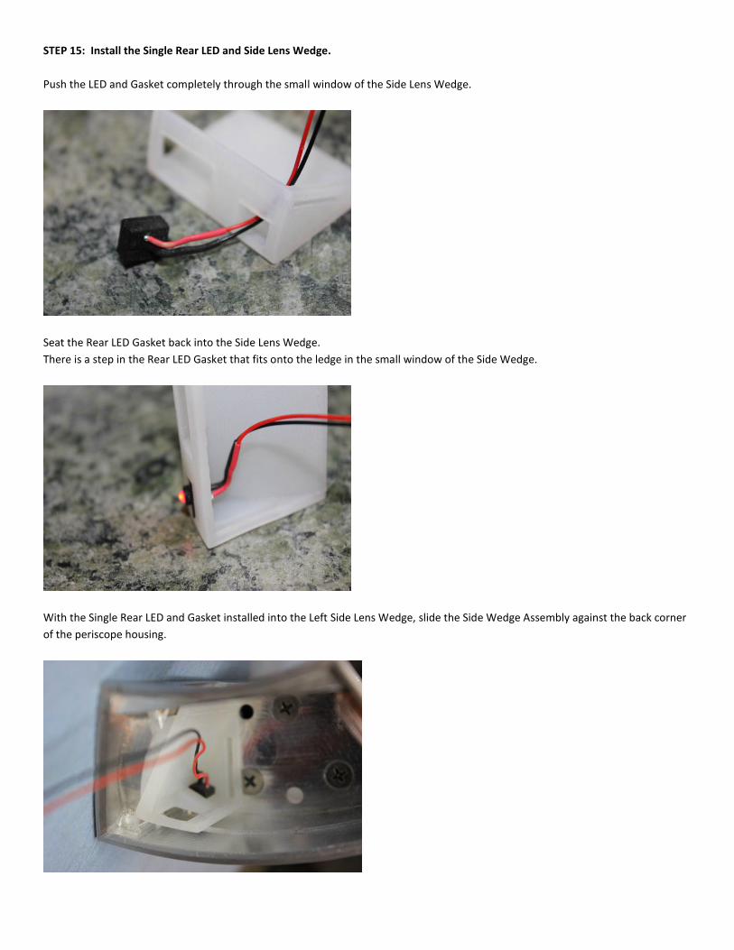
STEP 15: Install the Single Rear LED and Side Lens Wedge.
Push the LED and Gasket completely through the small window of the Side Lens Wedge.
Seat the Rear LED Gasket back into the Side Lens Wedge.
There is a step in the Rear LED Gasket that fits onto the ledge in the small window of the Side Wedge.
With the Single Rear LED and Gasket installed into the Left Side Lens Wedge, slide the Side Wedge Assembly against the back corner
of the periscope housing.

Gently (and patiently) work the Lip/Flange of the Single Rear LED Gasket through the opening in the periscope housing.
NOTE: The Rear LED Gaskets can be glued in place if desired. This will help hold the Rear LED’s in place while you assemble the
rest of your lighting kit and can prevent the Rear LED’s from being pushed into the housing.
The best adhesive to glue silicon rubber to the aluminum
housing (IMHO) is Devcon Multi-Purpose Silicon Adhesive.
Feel free to glue any of the Rubber Parts into place if you
wish. Make sure you clean the bond surface of each part.
NOTE: Do NOT glue anything until you test fit everything
Don’t forget to Paint your Periscope First (if you want it
painted )
_________________________________________________________________________________________________________

STEP 16: Install the Double Rear LED’s and Side Lens Wedge.
Poke double rear led gasket through the large hole in the side lens wedge
Push the Top and Bottom Lip/Flange of Double Rear LED Gasket through the holes in the periscope housing as shown below.
I use a pair of tweezers to push this into place. You can glue this if you wish.

Position the Side Lens into the periscope housing as shown
_________________________________________________________________________________________________________
STEP 17: Install the PCB Assembly into the Periscope Housing. (*** Daniel D/XENO ***)
Route the Power, Control, and Programming wires through the hole in the bottom of the Periscope Housing.
Insert the PCBA into the Periscope Housing with the PCBA towards the back of the Housing to allow clearance for the RED BLOCK
LED’s. Then push the PCBA forward – carefully aligning the RED BLOCK LED’s with the rectangular window in the Periscope Housing.
I prefer to pull the wires up and out of the way while inserting the PCBA into the Periscope Housing. I like to use a toothpick and
tweezers to push and pull things into place.
NOTE: The picture shows the Top
Programming Connector installed.
Do NOT solder this in – I only use I for
reprogramming.
This can cause a short against the Top Pie
Panel.
_________________________________________________________________________________________________________

STEP 18: Install the Top Rubber Gasket.
Insert the Top Rubber Gasket onto the PCBA. Push the Back Rubber Fins down into the housing and twist into place with a pair of
tweezers.
Tuck the wires down into the housing.
NOTE: Make sure to keep the Wires away from the Side LED’s and away from the Side Lens Wedges.
_________________________________________________________________________________________________________
_________________________________________________________________________________________________________

ROTOPOD PERISCOPE LIGHTING KIT for Daniel D. / Xeno PERISCOPE HOUSING
The assembly of the Daniel D. / Xeno Periscope Lighting Kit is very similar to the MCWHLR version. There are a few differences.
STEP 7**: Insert the Clear Light Pipes into the Black Front Rubber Gasket. (*** Daniel D/XENO ***)
Follow the instructions in Step 7 above – Note the difference in the Front Rubber Gasket.
_________________________________________________________________________________________________________
STEP 11**: Red Rear LED’s and Rubber Sleeves (*** Daniel D/XENO ***)
Install the Rear Red LED’s into the Rubber Sleeves as shown below.

Bend the LED leads and note that the Long LED leads solders to the (+) Red Wires and the Short LED leads solder to the Black Wires.
Insert the Rear LED and Rubber Gasket into the holes on the back of the periscope housing.
Glue the Rear Rubber LED Gaskets into place using an Adhesive similar to the Devcon Silicon Adhesive shown in Step 15 above.
Most of the Daniel D Periscope Housings only have two holes on the back. You can drill out the third hole if you wish.
See the Reference photo from the movie version below
_________________________________________________________________________________________________________

STEP 14**: Prepare the Rubber Side Lens Wedges. (*** Daniel D/XENO ***)
The internal housing of the Daniel D. Periscope is slightly narrower and longer that the MCWHLR design. This may prevent the
Rubber Side Lens from seating against the front corner of the periscope housing.
WRONG
Gap on Side Lens Rubber Side Lens Wedge pushed to back of Housing
I used the Rubber Tab that I removed during STEP 14-A above to fill the Gap between the Rubber Side Lens Wedge and the Back of
the Periscope Housing.
CORRECT
Rubber Spacer between Wedge and Housing NO Gap
_________________________________________________________________________________________________________

STEP 17**: Install the PCB Assembly into the Periscope Housing. (*** Daniel D/XENO ***)
Insert the Rear Rubber Spacer to push the PCBA against the front of the periscope housing.

I did not have access to the 3D files for the Daniel D/Xeno Periscope – so the Top Rubber Gasket was designed to be oversized.
The Top Edge of the Top Rubber Gasket can be trimmed flush with top edge of the periscope housing.
_________________________________________________________________________________________________________
_________________________________________________________________________________________________________
_________________________________________________________________________________________________________
PLEASE POST BUILD IDEAS AND ASSEMBLY TIPS TO ASTROMECH.NET
_________________________________________________________________________________________________________
_________________________________________________________________________________________________________
_________________________________________________________________________________________________________
!!! THANK YOU !!! ROTOPOD
Droidvillage.net