rotational speed sensors kmi15/16 - nxp … gear wheel structure..... 20 4.5 position tolerances...
TRANSCRIPT

PhilipsSemiconductors
APPLICATION NOTE
Rotational Speed SensorsKMI15/16
AN98087

Philips Semiconductors
Rotational Speed SensorsKMI15/16
Application NoteAN98087
2
Abstract
The sensor modules of KMI 15 and KMI 16 series provide a simple and cost effective solution for rotationalspeed measurement in both automotive and industrial applications. They consist of a magnetoresistive sensorelement, a permanent magnet fixed to it and an integrated signal conditioning circuit. Application relevant itemssuch as mounting, electrical properties and possible encapsulation are discussed. Test results of theelectromagnetic compatibility are shown and an interface circuit for improved protection of the sensor module isproposed.
© Philips Electronics N.V. 1999
All rights are reserved. Reproduction in whole or in part is prohibited without the prior written consent of thecopyright owner. The information presented in this document does not form part of any quotation or contract, isbelieved to be accurate and reliable and may be changed without notice. No liability will be accepted by thepublisher for any consequence of its use. Publication thereof does not convey nor imply any license underpatent- or other industrial or intellectual property rights.

Philips Semiconductors
Rotational Speed SensorsKMI15/16
Application NoteAN98087
3
Author(s): Fritz Schmeißer, Klaus Dietmayer
Systems Laboratory HamburgGermany
APPLICATION NOTE
Rotational Speed SensorsKMI15/16
AN98087
Keywords
Rotational Speed SensorsContactless Speed Measurement
Magnetoresistive SensorsIntegrated Signal Conditioning
Date: 1999-01-11
Philips Semiconductors
Rotational Speed SensorsKMI15/16
Application NoteAN98087
4
Summary
The rotational speed sensors KMI 15/x and KMI 16/x make use of the magnetoresistive effect. They consist of
the magnetoresistive sensor element, a permanent magnet fixed to this sensor and an integrated signal
conditioning circuit. The magnetoresistive principle offers a number of advantages compared with Hall-Effect
sensors or inductive sensors such as measurements down to zero speed and a better signal to noise ratio.
The integrated signal conditioning electronics of the sensor modules KMI 15/x or KMI 16/x amplifies the small
output voltage of the sensor element and converts it to a digital output signal. This signal is either a rectangular
modulation of the supply current for two-wire technology (KMI 15/x) or a switched output voltage with open
collector (KMI 16/x). Both sensor modules meet high the requirements of the automotive industry regarding
electromagnetic compatibility to line conducted and radiated interference. Although the KMI sensor modules are
designed for automotive applications, they also can be used advantageous for rotational speed measurement
and movement detection in a wide range of industrial applications.

Philips Semiconductors
Rotational Speed SensorsKMI15/16
Application NoteAN98087
5
Table of Contents
1. INTRODUCTION ............................................................................................................................................ 7
2. ROTATIONAL SPEED MEASUREMENT USING MAGNETORESISTVE SENSORS................................. 8
3. MAGNETORESISTIVE ROTATIONAL SPEED SENSORS......................................................................... 103.1 The Magnetoresistive Sensor Element ............................................................................................. 10
3.1.1 The Magnetoresistive Effect ................................................................................................. 103.1.2 Linearisation of Sensor Characteristic .................................................................................. 103.1.3 Flipping ................................................................................................................................. 11
3.2 Principle of Speed Measurement...................................................................................................... 123.2.1 Passive Targets Wheel......................................................................................................... 123.2.2 Active Target Wheel ............................................................................................................. 14
3.3 The Integrated Signal Conditioning Circuit ....................................................................................... 153.4 Product Overview.............................................................................................................................. 163.5 Limiting Electrical Conditions and Protection .................................................................................... 17
4. PROPERTIES OF THE SENSOR MODULES ............................................................................................. 184.1 Sensing Distance and Hysteresis ..................................................................................................... 184.2 Temperature Coefficient ................................................................................................................... 194.3 Eddy Currents ................................................................................................................................... 194.4 Gear Wheel Structure ....................................................................................................................... 204.5 Position Tolerances .......................................................................................................................... 204.6 External Magnetic Fields................................................................................................................... 22
5. ENCAPSULATION OF THE KMI SENSORS............................................................................................... 235.1 Plastic Encapsulation........................................................................................................................ 235.2 Bending of Connection Pins.............................................................................................................. 23
6. APPLICATION CIRCUIT AND ELECTROMAGNETIC COMPATIBILITY................................................... 256.1 Test and Application Circuit .............................................................................................................. 256.2 Line Conducted Interferences........................................................................................................... 256.3 Radiated Interference ....................................................................................................................... 266.4 Electrostatic Discharge ..................................................................................................................... 26
7. INTERFACE TO DIGITAL SIGNAL PROCESSING FOR KMI 15/X............................................................ 277.1 General ............................................................................................................................................. 277.2 The Comparator................................................................................................................................ 277.3 Signal Filter ....................................................................................................................................... 297.4 Protection Circuit............................................................................................................................... 29
8. OTHER APPLICATIONS.............................................................................................................................. 30

Philips Semiconductors
Rotational Speed SensorsKMI15/16
Application NoteAN98087
6
Philips Semiconductors
Rotational Speed SensorsKMI15/16
Application NoteAN98087
7
1. INTRODUCTION
The KMI 15/X and KMI 16/x are magnetoresistive sensor modules with an integrated signal conditioning
electronics to provide a simple and cost effective solution for rotational speed measurements. Due to their
compact design, they are simple to design-in and therefore time-to-market is significantly reduced.
The KMI sensor modules consist of the magnetoresistive sensor element, a permanent magnet fixed to this
sensor and the integrated signal conditioning circuit designed in bipolar technology. Compared with other
sensing techniques, the magnetoresistive technology has a number of practical advantages such as:
• Wide air gap due to high basic sensitivity of the magnetoresistive effect
• Wide operating frequency range, including zero speed detection
• Insensitive to vibration
• Wide operating temperature range
• High EMC
The KMI sensor modules provide two different interfaces to the application. The KMI 15/x sensor modules have
an interface using a digital modulation of the supply current and therefore require only a two-wire connection to
the application circuit. This current interface is recommended if signals have transmitted over longer distances.
On the other hand, also a 3-pin open-collector version (KMI 16/x) is available in order to fit more easily in
standard applications. The signal conditioning IC and the sensor element are physically separated to improve
high temperature performance of the KMI sensors. This construction ensures that the sensor element can be
exposed to higher temperatures than the IC and power dissipation of the IC will not cause inhomogeneous heat
in the sensor element.
The first part of this report gives an introduction into the principles of rotational speed measurement using
magnetoresistive sensors. Then the characteristics of the magnetoresistive element and the on-chip signal
conditioning circuits are described in more detail. Correct mounting of the sensor is another item to be taken into
account from the application point of view. Some hints are given for correct encapsulation, including the effects
and failures caused by non-ideal mounting. Another important item is the EMC performance of the sensor
modules for which test results are given. Finally, a proposal is made for an advanced application circuit.
Philips Semiconductors
Rotational Speed SensorsKMI15/16
Application NoteAN98087
8
2. ROTATIONAL SPEED MEASUREMENT USING MAGNETORESISTVE SENSORS
Rotational speed measurement using magnetoresistive sensors (MR-sensors) is achieved by counting
ferromagnetic marks, such as teeth of a passive gear wheel or the number of magnetic elements of magnetised
ring. Beside magnetoresistive sensors also the inductive sensors and Hall-Effect sensors can be used for this
task. However, the magnetoresistive effect offers some essential advantages which should be mentioned briefly.
First, the output signal level of a MR sensor does not vary with rotation speed, as it is the case in inductive
sensor systems. Inductive sensors show a direct relation between the rotational speed and the output amplitude
and therefore require sophisticated electronics to evaluate the large signal voltage range, especially in
applications requiring low jitters.
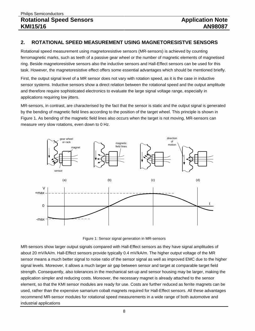
MR-sensors, in contrast, are characterised by the fact that the sensor is static and the output signal is generated
by the bending of magnetic field lines according to the position of the target wheel. This principle is shown in
Figure 1. As bending of the magnetic field lines also occurs when the target is not moving, MR-sensors can
measure very slow rotations, even down to 0 Hz.
gear wheelor rack
magnet
magneticfield lines
(a) (b) (c)
directionof
motion
(d)
sensor
V
t0
+max
-max
Figure 1: Sensor signal generation in MR-sensors
MR-sensors show larger output signals compared with Hall-Effect sensors as they have signal amplitudes of
about 20 mV/kA/m. Hall-Effect sensors provide typically 0.4 mV/kA/m. The higher output voltage of the MR
sensor means a much better signal to noise ratio of the sensor signal as well as improved EMC due to the higher
signal levels. Moreover, it allows a much larger air gap between sensor and target at comparable target field
strength. Consequently, also tolerances in the mechanical set-up and sensor housing may be larger, making the
application simpler and reducing costs. Moreover, the necessary magnet is already attached to the sensor
element, so that the KMI sensor modules are ready for use. Costs are further reduced as ferrite magnets can be
used, rather than the expensive samarium cobalt magnets required for Hall-Effect sensors. All these advantages
recommend MR-sensor modules for rotational speed measurements in a wide range of both automotive and
industrial applications

Philips Semiconductors
Rotational Speed SensorsKMI15/16
Application NoteAN98087
9
The KMI sensor modules of Philips Semiconductors can also be used to measure direction of rotation. This
requires two sensor modules placed to the target wheel at different positions. An extended signal conditioning
electronic has to evaluate the phase difference between the signals of these two sensor modules.

Philips Semiconductors
Rotational Speed SensorsKMI15/16
Application NoteAN98087
10
3. MAGNETORESISTIVE ROTATIONAL SPEED SENSORS
3.1 The Magnetoresistive Sensor Element
3.1.1 The Magnetoresistive Effect
Magnetoresistive (MR) sensors make use of the magnetoresistive effect, the property of a current carrying
magnetic material to change its resistivity in the presence of an external magnetic field. Figure 2 shows a strip of
ferromagnetic material, called permalloy (20% Fe, 80% Ni).
H
Magnetization
Current
Permalloy
α
R = R0 + ∆ R cos² α
α = 0° Ø Rmax
α = 90° Ø Rmin
Figure 2: The magnetoresistive effect in permalloy
When no external magnetic field is present, the permalloy has an internal magnetisation vector parallel to the
current. During deposition of the permalloy strip, a strong external magnetic field is applied parallel to the strip
axis. This accentuates the inherent magnetic anisotropy of the strip and gives them a preferred magnetisation
direction, so that even in the absence of an external magnetic field , the magnetisation will always tend to align
with the strips. If an external magnetic field H is applied, parallel to the plane of the permalloy but perpendicularto the current flow, the internal magnetisation vector of the permalloy will rotate around an angle α. As a result,
the resistance R of the permalloy will change as a function of the angle α, as given by:
α20 cos⋅∆+= RRR
R0 and ∆R are material parameters. ∆R is in the range of 2 to 3% of R0.
3.1.2 Linearisation of Sensor Characteristic
It is obvious from this quadratic equation that the resistance to magnetic field relation is non-linear and in addition
not unambiguous (compare with graph a) in Figure 4). To get a usable magnetic field sensor with a preferably
linear characteristic, a more sophisticated design is necessary.
The magnetoresistive effect can be linearized by depositing aluminum stripes (called barber poles) on top of the
permalloy strip at an angle of 45° to the strip axis. Figure 3 shows the principle. As aluminium has a much higher
conductivity than permalloy, the effect of the barber pole is to rotate the current direction by 45°, effectivelychanging the angle between the magnetisation and the electrical current from α to (α - 45°). Graph b) in Figure 4
shows the impact on the sensor characteristic due to the barber pole structure.

Philips Semiconductors
Rotational Speed SensorsKMI15/16
Application NoteAN98087
11
.
II
MagnetizationPermalloy
Barber pole
Figure 3: Linearization of the magnetoresistive effect
a
b
Figure 4: a) R-H characteristic of a standard sensor, b) R-H characteristic of barber pole sensors
To build up a complete sensor element, a Wheatstone bridge arrangement consisting of four magnetoresistive
elements is used. In this arrangement, diagonal elements have barber poles of the same orientation. This means
that one diagonal pair has barber poles orientated +45° to the strip axis, while the other pair has an orientation of
-45°. This ensures a doubling of the output signal while still having an almost linear output signal. Moreover, the
inherent temperature coefficients of the four bridge resistances are mutually compensated.
3.1.3 Flipping
Although the “flipping” of MR sensors does not affect the KMI sensor modules due to their stabilisation magnets,
the effect should be mentioned for completeness.
The internal magnetisation of the sensor strip has two stable positions. So, if for any reason the sensor is
influenced by a powerful magnetic field opposing the internal field, the magnetisation may switch or ”flip” from its
present direction into the opposite direction. As demonstrated in Figure 5 this leads to a reversal of the sensor
characteristic. Consequently, to ensure stable operation, it must be avoided to operate the sensor in an
environment where the sensor is subjected to strong negative external fields (”-Hx”). Preferably, a positive
(”+Hx”) auxiliary field of sufficient magnitude should be applied to prevent any likelihood of flipping within the
intended operating range of Hy.

Philips Semiconductors
Rotational Speed SensorsKMI15/16
Application NoteAN98087
12
Figure 5: Reversal of sensor characteristic caused by flipping
For the sensor types KMI 15/1, KMI 15/4 and KMI 16/1, this stabilisation field is provided by a magnetic field
component in x-direction of the operation magnet. This is field component is attained by an angled magnetisation
(see Figure 7). The types KMI 15/2 and KMI 16/2 intended for active targets and therfore not requiring a magnet
for operation, are fitted with a smaller auxiliary permanent magnet, magnetised in X-direction only.
3.2 Principle of Speed Measurement
The MR-sensor cannot directly measure rotational speed but is sensitive to the motion of toothed wheels made
from ferrous material (passive targets) or rotating wheels having alternating magnetic poles (active targets).
3.2.1 Passive Targets Wheel
The principle of operation has already been briefly discussed in section 2. Figure 1 shows the general
arrangement for a passive target wheel.
The sensor is fitted with a permanent magnet. Without a ferromagnetic target or a symmetric position of the
toothed wheel, no component of the magnetic field would be in the sensitive direction (y-direction) and therefore
the sensor output would be zero. For non-symmetric positions, for example if the passive target rotates in front of
the sensor, the magnetic field is bent according to the actual wheel position and an alternating field component in
the y-direction arises. This alternating field component is used to generate an output signal that varies according
to the wheel position. The amplitude of the sensor output voltage depends on the magnetic field strength of the
biasing magnet, the distance between sensor and target and, obviously, on the structure of the target. Large
solid targets will give stronger signals at larger distances from the sensor than small targets.
The terms to describe the structure of a gear wheel are explained in TABLE 1 and Figure 6. Figure 7 shows the
enlarged drawing of the complete sensor module for passive target wheels. The direction of magnetisation
ensures a component of the magnetic field in x-direction to prevent the sensor from flipping (compare with
section 0).

Philips Semiconductors
Rotational Speed SensorsKMI15/16
Application NoteAN98087
13
SYMBOL DESCRIPTION UNITDINz number of teethd Diameter mmm module m= d / z mmp pitch p = p m mmASAPD pitch diameter inchDP diametric pitch DP = z/PD 1/inchCP circular pitch CP = p/DP inchFor conversion from ASA to DIN : m = 25.4 mm/DP ;p = 25.4 x CP
TABLE 1: Gear wheel dimensions
pitch
pitchdiameter
Figure 6: Gear wheel dimensions
y z
x x
IC
sensor
magnet withdirection ofmagnetization
Figure 7: Component detail of the sensor KMI15/1 for passive target wheels
Philips Semiconductors
Rotational Speed SensorsKMI15/16
Application NoteAN98087
14
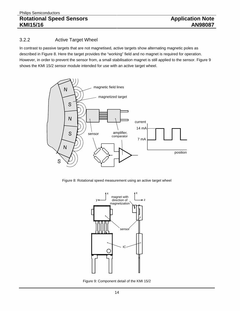
3.2.2 Active Target Wheel
In contrast to passive targets that are not magnetised, active targets show alternating magnetic poles as
described in Figure 8. Here the target provides the “working” field and no magnet is required for operation.
However, in order to prevent the sensor from, a small stabilisation magnet is still applied to the sensor. Figure 9
shows the KMI 15/2 sensor module intended for use with an active target wheel.
amplifier,comparator
sensor
magnetic field lines
magnetized target
position
current
14 mA
7 mA
Figure 8: Rotational speed measurement using an active target wheel
y z
x x
IC
sensor
magnet withdirection of
magnetization
Figure 9: Component detail of the KMI 15/2

Philips Semiconductors
Rotational Speed SensorsKMI15/16
Application NoteAN98087
15
The structure of an active target can be expressed similarly to that for passive targets (see TABLE 1). In this
case, a north-south magnetic pole pair represents a tooth-valley pair.
The achievable maximum sensing distance for an active wheel depends on the field strength and the structure of
the magnetic poles. Figure 10 gives the relation between maximum air gap and pitch for typical plastoferrite
rings. This graph was found by averaging measurement results of different target wheels.
0
1
2
3
4
5
0 1 2 3 4 5 6 7pole pitch / mm
airg
ap/m
m
Figure 10: Maximum air gap versus pole pitch for active target wheels.
3.3 The Integrated Signal Conditioning Circuit
The rotational speed sensors KMI 15/x and KMI 16/x include an advanced bipolar signal conditioning circuitry.
The KMI 16/x sensor modules provide an open collector output, while KMI 15/x sensor modules have a current
interface that requires only two-wires to connect them in the application.
Figure 11 shows the block diagram of the KMI 15/x sensor modules, while the block diagram of the KMI 16/x
modules is given in Figure 12. The only difference between both is that for the KMI16/x the switchable current
source, which generates the modulated output current signal, is replaced by an open collector output. Moreover,
the KMI 16/x sensors allow operation at 5V supply voltage and therfore directly provide a digital output at
standard voltage levels.
SCHMITTTRIGGER
AMPLIFIERSENSOR SWITCHABLECURRENTSOURCE
CONSTANTCURRENTSOURCEVOLTAGE CONTROL VCC
V
Figure 11: Block diagram of the KMI 15/x sensors with current interface

Philips Semiconductors
Rotational Speed SensorsKMI15/16
Application NoteAN98087
16
SCHMITTTRIGGER
AMPLIFIERSENSOR
VOLTAGE CONTROL VCC
Voutopen collectoroutput
GND
Figure 12: Block diagram of the KMI16/x sensors with open collector output.
Figure 13 shows a more detailed circuit diagram of the KMI 15/x sensor modules. After passing the EMC filter,
the sensor signal is amplified and then digitised by a comparator. The comparator has a built-in hysteresis in
order to avoid switching due to noise. The voltage control block is stabilised by a bandgap reference diode. It
provides the 5 V power supply for the sensor, the amplifier and the comparator. The KMI 15/x modules use two
current sources. One current source generates a basic current of 7 mA, which is used for the internal power
supply. The current of the second, 7 mA current source is added when triggered by the digitised sensor signal.
Thus, during operation, the output current, Icc, switches between 7 mA and 14 mA.
-V
Figure 13: Sensor signal conditioning circuit of the KMI 15/x sensors
3.4 Product Overview
TABLE 2 gives an overview on the complete KMI family. As explained in the previous sections, the KMI 15/x
types offer a current source output requiring only two wires for connection. The KMI 16/x sensors have separate
signal outputs implemented as open collectors. For each of these interface types, there is at least one sensor
module available for passive target wheels and another type for active target wheels. These sensor modules
differ only by size and magnetisation direction of the magnet fitted to it.

Philips Semiconductors
Rotational Speed SensorsKMI15/16
Application NoteAN98087
17
Type Interface Target Wheel SensingDistance in mm
Package Availability
KMI 15/1 Current source Passive ferrom. 2.5 SOT453 Now
KMI 15/2 Current source Magnetised 2.5 SOT453 Now
KMI 15/4 Current source Passive ferrom. 2.0 SOT453 Now
KMI 16/1 Open collector Passive ferrom. 2.5 SOT477 Now
KMI 16/2 Open collector Magnetised 2.5 SOT477 Q1 ‘99
TABLE 2: Product overview
3.5 Limiting Electrical Conditions and Protection
The following Table 3 shows the limiting conditions for the KMI15 and KMI16.
Item KMI16/x KMI15/x Remarks
Supply Voltage 4.5V to 16V 5.5V to 16V
Load DumpProtection
Yes* Yes* *Max. 40V, 2s
Reverse Polarity No No
Table 3: Limiting Conditions of KMI15 and KMI16

Philips Semiconductors
Rotational Speed SensorsKMI15/16
Application NoteAN98087
18
4. PROPERTIES OF THE SENSOR MODULES
4.1 Sensing Distance and Hysteresis
The sensing distance d is defined as the distance between the front of the sensor and the tips of the teeth,
measured on the central axis of the magnet (see Figure 14). Above a certain value of d, Icc ceases to vary
between 7 mA and 14 mA and remains constant at one of these values. The sensor signal, which decreases with
larger sensing distances, has become too small to be recognised by the signal conditioning electronics.
gear wheel
sensor
d d
Figure 14: Definition of the sensing distance d
The KMI 15/x and KMI 16/x sensors are able to generate a stable digital output signal in a large range of sensing
distances. They have a built-in hysteresis to avoid unwanted switching of the sensor due to
• Mechanical vibration of the sensor or the gear wheel
• Electrical interference
• Circuit oscillation at very low rotational speed
A larger hysteresis provides a better immunity to disturbances but, on the other hand, reduces the maximum
sensing distance d, as the sensor signal must exceed the hysteresis levels to be recognised. Consequently, a
compromise has to be found between hysteresis and sensing distance.
Vsens Iout
IH
IL
Sensor-Offset
t
Hysteresis
3 mV
-3 mV
0
Figure 15: Sensor output voltage and hysteresis

Philips Semiconductors
Rotational Speed SensorsKMI15/16
Application NoteAN98087
19
For the KMI sensors, the hysteresis is set to +/- 3 mV at room temperature (see Figure 15). Consequently, the
maximum attainable sensing distance is achieved when the sensor signal reaches the level of 6 mV peak-to-
peak. Note that this limit assumes a zero sensor signal offset.
4.2 Temperature Coefficient
MR-sensors have negative temperature coefficients of about -0.4 %/K. This means that the amplitude of the
sensor signal goes down at higher temperatures. Without compensation, or in other words, without an adaptation
of the hysteresis levels, this effect would reduce the maximum sensing distance d at higher temperatures.
Therefore the KMI sensor modules provide an automatic adaptation of the hysteresis levels with temperature.
Figure 16 shows the residual temperature dependency of the maximum sensing distance.
50 0 200
4
3
1
0
2
50 100
0 1 52 3 f (kHz)
T in °Camb
o
d(T); f = 2 kHz
t
t
150
din
mm
Figure 16: Maximum sensing distance d as a function of temperature and tooth frequency (KMI 15/1)
4.3 Eddy Currents
The movement of the ferromagnetic wheel in the magnetic field of the sensor system will induce eddy currents in
the wheel. These eddy currents also cause a (secondary) magnetic field, superimposed to the operating field in
the sensor. This secondary field generates an offset voltage in the sensor signal. The eddy currents and
therefore the resulting offsets are nearly proportional to the rotational speed of the wheel. As a result, this effect
slightly reduces the maximum sensing distance at higher frequencies. The function between rotational speed and
maximum sensing distances is also shown in Figure 16.
The direction of the eddy currents and consequently sign of the generated secondary magnetic field depends on
the direction of rotation. This means that the external field can increase or compensate a residual offset voltage
of the sensor and therefore may cause a direction dependent change of the maximum achievable sensing
distance. Consequently, also the duty cycle of the output signal of nominal 50% (without any offset) may slightly
depend on the direction of movement.

Philips Semiconductors
Rotational Speed SensorsKMI15/16
Application NoteAN98087
20
4.4 Gear Wheel Structure
Finally the structure of the gear wheel itself will affect the maximum sensing distance. Figure 17 shows the
variation of the maximum sensing distance d in dependence of the module m for a KMI15/1 sensor. Large solid
targets will give stronger signals than small targets. In general, the “size” of the structure can be described as a
relationship between wheel diameter and the number of teeth (see also TABLE 1: Gear wheel dimensions).
module m in mm
1
0.5
1.5
00
1 2 3 4 5
ddo
Figure 17: Normalised maximum sensing distance as a function of the module m for the KMI 15/1-sensor module
4.5 Position Tolerances
The optimum position of the sensor is symmetrical to the target wheel with respect to all degrees of freedom.
Deviations from this position may reduce the amplitude of the MR-sensor output or increase signal offset, which,
in consequence, reduces the maximum sensing distance. Significant larger or smaller values for the duty cycle of
nominal 50% indicate that there is an additional offset caused by wrong mounting. There are three possible
mounting errors that have to be taken into account:
1
2
4
3
2 3 40
d
0 1y in mm
y
din
mm
Figure 18: Sensing distance as a function of positional tolerance in the y-axis for a KMI15/1-sensor module.

Philips Semiconductors
Rotational Speed SensorsKMI15/16
Application NoteAN98087
21
The first possible error is a shift in y-direction relative to the optimum sensor position as defined in Figure 18.
The graph in Figure 18 shows the sensing distance as a function of an y-axis shift. It is recommended to keep
this shift smaller than 0.5 mm in order not to have a significant loss of performance.
The second effect to be taken into account is an angular error as defined in Figure 19. This error should be kept
smaller than 1 degree for adequaete operation.
Layer 1handbook, halfpage
2
4
3
0 10
1
d
Θ
2 3 4Θ in °
din
mm
Figure 19: Sensing distance as a function of the angular error for the KMI15/1
An axial shift of the position in x-direction is not very critical with respect to the performance of the KMI sensor
modules. Figure 20 shows the definition of this position error and gives some values for the KMI15/1. The graph
is non-symmetrical due to the effect that a field component in x-direction already exist to prevent the sensor from
flipping and this partitioning is changed by this position error. The optimum position is x = 0.
x in mm
1
2
4
3
0
x
d
10 mm
0 2 4 6-6 -4 -2
din
mm
Figure 20: Sensing distance as a function of positional tolerance in the x-axis
A tilt in y-z plane has negligible impact on the sensing distance for angles less than 4°. Therefore, this error
normally has not to be considered.

Philips Semiconductors
Rotational Speed SensorsKMI15/16
Application NoteAN98087
22
4.6 External Magnetic Fields
External magnetic fields if present are added to the operating field and therefore may cause an additional offset
voltage. If this offset exceeds a certain limit (see e.g. Figure 15) an unacceptable change in duty cycle or even
malfunction may occur. Sources of external magnetic fields are all kind of permanent magnets and
electromagnetic devices like motors and relais, but also simple wires carrying high currents may cause significant
magnetic fields. What level of disturbances is tolerable depends on the sensing distance required. In general,
sensor modules should be mounted as far away as possible from all sources of magnetic fields. What external
field strength is tolerated depends on the sensing distance required and therefore must be decided individually.
Another aspect to be taken into account is that very strong external fields may damage the sensor as they may
permanently change the magnetisation of the attached permanent magnet. Magnetic fields up to a field strength
of H = 5 kA/m are tolerated regarding this issue but already may significant influence the sensor performance.

Philips Semiconductors
Rotational Speed SensorsKMI15/16
Application NoteAN98087
23
5. ENCAPSULATION OF THE KMI SENSORS
5.1 Plastic Encapsulation
The KMI rotational speed sensor comes in special package patented by Philips that is predestined for customer
specific encapsulation. Thanks to this package, the sensor modules are highly insensitive to mechanical stress.
They can be easily built into a customised moulding, but some precautions should be taken into account to
ensure full performance.
During plastic encapsulation the plastic material must not be injected directly to the MR-sensor or the integrated
circuit because this may cause remaining mechanical stress in these parts. Furthermore it had to be ensured that
the high temperature of the injected plastic material does not affect the durability of the gluing of the auxiliary
magnet. High temperature and pressure could change the position of the magnet and therefore may damage the
offset trimming.
The MR-sensor element is placed directly on the leadframe. Two reference points, which are part of this
leadframe, can be used in the system design as reference mark. As the tolerances of the plastic encapsulation
are no longer part of the overall tolerance calculation, this effect allows a precise sensor positioning and
consequently a larger air gap.
Figure 21 shows the drawing of the lead frame with the reference points, the MR-sensor, the integrated signal
conditioning circuit and the sensor package. The exact mechanical dimensions can be found in the current data
book.
Figure 21: Construction and encapsulation of the KMI sensor modules.
5.2 Bending of Connection Pins
The electrical connections between the MR-sensor and the integrated circuit can be bent to adapt the sensor
element position to the actual application. However, the maximum force to the connections between sensor
element and IC must be limited to F=20 N in order not to destroy the device during this process.
The external connections to the supply pins should be fixed by clamping in order to avoid any tractive force to the
leadframe in the sensor package. The maximum force allowed for this pins is F = 50 N.

Philips Semiconductors
Rotational Speed SensorsKMI15/16
Application NoteAN98087
24
The limiting values for bending are given in the following Figure 22.
Figure 22: Limiting conditions for bending

Philips Semiconductors
Rotational Speed SensorsKMI15/16
Application NoteAN98087
25
6. APPLICATION CIRCUIT AND ELECTROMAGNETIC COMPATIBILITY
6.1 Test and Application Circuit
Figure 23 shows a test circuit to convert the current signal of the KMI 15/x sensor modules into a voltage.
Figure 24 shows the respective circuit for the KMI16/x with open collector. Dependent on the actual conditions in
the application, these simple circuits must be extended by protective components. An example for automotive
applications is given in the next section.
V
CR
SENSOR
GND
CC
ICC
L L
V
Usignal
V
SENSOR
GND
CC
ICC
Vout10 kΩ
2.7 kΩ
2.2 nF
Figure 23: Test circuit for KMI15/x Figure 24: Test Circuit for KMI 16/x
6.2 Line Conducted Interferences
Figure 25 shows the recommended application circuit for KMI 15/x sensor modules in automotive applications. It
adds some measures to improve electromagnetic compatibility. Spikes of positive or negative polarity are
suppressed and also a protection against reverse polarity of the supply voltage is included.
CLRLC1115Ω
100nF
100nF
D2
D1
BZTO3C36
1N4003
+V
GND
V
V
CCSENSOR
Figure 25: Recommended application circuit for the KMI15/x sensors
TABLE 4 lists the test results found for this circuit for line-conducted disturbances according to ISO 7637-1. It
should be noted that this circuit does not protect the device against the “load dump pulse” (test pulse 5 according
to ISO 7637-1). Protection against this pulse would require a special suppressor diode with sufficient energy
absorption capability. However, as board nets of cars often already contain a central load dump protection that
limits the pulse voltage to Vmax = 40 V, this kind of protection is not required in any case.

Philips Semiconductors
Rotational Speed SensorsKMI15/16
Application NoteAN98087
26
EMC REF.ISO 7637-1
MIN. ( V ) MAX.( V ) Remarks Severityclass
Test pulse 1 -100 - td = 2 ms CTest pulse 2 - 100 td = 0.2 ms ATest pulse 3a -150 - td = 0.1 µs ATest pulse 3b - 100 td = 0.1 µs ATest pulse 4 -7 - td = 130 ms BTest pulse 5 120 td = 400 ms see text
TABLE 4: Test results regarding line conducted interferences
6.3 Radiated Interference
Any sensitive electronic system connected to other equipment by cables is exposed to electromagnetic
disturbances. The KMI 15/x and KMI 16/x sensor modules provide RF-filter in the input stage to avoid negative
effects on the system performance. The sensors were tested under standardised conditions in a “strip-line”
according to ISO 11425-5. Tests were passed at a maximum field strength of E = 150 V/m with and without AM
modulation (1kHz, 95%). Actual applications, however, may lead to different results due to special environment
characteristics such as resonance effects. Therefore it is strongly recommended to do final tests regarding EMC
in the application relevant environment.
6.4 Electrostatic Discharge
During handling and mounting electrostatic charges may affect the sensor pins and under extreme conditions
even damage or destroy the sensor. Tests for electrostatic discharges (ESD) were conducted in line with
IEC 801-2 to safeguard the handling capability of the KMI sensor modules. The IEC 801-2 test conditions were:
C = 150 pF, R = 150 Ω. V = 2 kV
These data are only valid for the supply pins, but no protective means are provided for the connections between
sensor element and the IC. Common rules for handling electrostatic sensitive devices must be observed.

Philips Semiconductors
Rotational Speed SensorsKMI15/16
Application NoteAN98087
27
7. INTERFACE TO DIGITAL SIGNAL PROCESSING FOR KMI 15/X
7.1 General
The integrated rotational speed sensor KMI 15/x provides a modulated current. For subsequent digital signal
processing, this current signal has to be converted to a ground referenced voltage signal, matching the logic
levels of the processing unit. Additionally, the signal conditioning circuit should include a low pass filter in front of
the comparator input and protective elements to suppress line conducted interference. Figure 26 shows the block
diagram of a suitable application circuit. Details are discussed in the following sections.
Please note that the KMI16/x sensors already provide a digital output implemented as an open collector. As
these modules can operate at 5V supply voltage, the standard level for digital systems, these types should be
preferred in digital systems if the advantages of the two-wire current interface are not that important.
ProtectionCircuit
Filter Comparator
SensorKMI15/x
RL CL
GND
Vout
V+
VDD
Figure 26: Block diagram of a suitable application circuit
Please note that the KMI16/x sensors already provide a digital output implemented as an open collector. As
these modules can operate at 5V supply voltage, the standard level for digital systems, these types should be
preferred in digital systems if the advantages of the two-wire current interface are not that important.
7.2 The Comparator
Figure 27 illustrates the output current levels regarding nominal values and specified tolerances.
IHmin
IHmax
IAV
ILmax
ILmin
IHnom
ILnom
time
current
Figure 27: Current levels of the rectangular output signal

Philips Semiconductors
Rotational Speed SensorsKMI15/16
Application NoteAN98087
28
Using the recommended series resistor of 115 Ω, the current levels are converted into voltages as given in
TABLE 5. Consequently, the comparator levels of a processing electronic must be set between VHmin and VLmax for
reliable operation. This is ensured by using a reference level of VAV . Additionally, a hysteresis should be
implemented.
SymbolsCurrent
Current in mA voltage in V@ R = 115 Ω
SymbolsVoltages
ILmin 5.6 0.64 VLmin
ILnom 7 0.81 VLnom
ILmax 8.4 0.97 VLmax
IAV 1.13 VAV
IHmin 11.2 1.29 VHmin
IHnom 14 1.61 VHnom
IHmax 16.8 1.93 VHmax
TABLE 5: Output current and voltage levels for R = 115 Ω
The complete circuit diagram proposed for such an application is depicted in Figure 28. The dimension is made
assuming a 5V supply voltage (VDD) for the comparator. The reference voltage VAV is defined by voltage divider
R5/R6. The voltage divider R9/R10, the feed back resistor R7 and the input resistors R2 and R3 determine the
hysteresis of about +/- 50 mV.
-
+10 k
470k
47k
47k15k
2k243k
115 Ω
0.1µ220µ
GND
VDD
KMI 15/x
C3 C2D2
D1
C1
0.1µ
R1 C4
4.7n
R3
4.7k
R2LM 393
R5
R6
R8
R9
R10
Vout
V+
1N4003
BZT03C36
R7
Figure 28: Complete application circuit for digital signal processing with the KMI 15/x sensor modules

Philips Semiconductors
Rotational Speed SensorsKMI15/16
Application NoteAN98087
29
7.3 Signal Filter
In addition to the parallel capacitor C1, a second lowpass filter is recommended to reduce RF interference. The
example circuit in Figure 28 provides a first-order RC low pass filter for this task (R3, C4) with a cut off frequency
of 10 kHz. This cut off frequency should be adapted according to the maximum signal frequency required in the
application in order to achieve an optimum absorption of noise.
7.4 Protection Circuit
This part of the circuit has already be described in section 0. The series diode D1 protects the sensor and
electronics against reverse polarity of the supply voltage and blocks negative interference pulses. The
suppressor diode D2 limits positive interference pulses. Note that the specified type has not the capability to
tolerate the load dump pulses. The capacitor C2 absorbs fast positive and negative interference pulses. The
electrolytic capacitor C3 stores energy to supply the sensor during short supply voltage breakdown due to
negative pulses.

Philips Semiconductors
Rotational Speed SensorsKMI15/16
Application NoteAN98087
30
8. OTHER APPLICATIONS
The primary application area of the KMI sensors is rotational speed measurement in automotive applications
such as ABS, ASR or gearbox. However, the magnetoresistive rotational speed sensors of the KMI-family are not
limited to automotive applications. Their characteristic recommends them for a wide range of general industrial
applications. Another range of industrial applications is the detection of non-periodic or single events, where a
movement can be transferred to a change of a magnetic field. Examples are:
• Proximity switch
• Position detector
• Limit switch
• Detection of electrical current levels
The common operating principle of these applications is that a moving ferromagnetic part, a moving permanent
magnet or changes of the electrical current cause an alteration of the magnetic field measured by the MR sensor
and, in consequence, forces an alteration of the output signal. The sensors of the KMI family offer simple, reliable
and cost effective solutions also for this kind of applications.