rotational speed dependent motor properties
TRANSCRIPT
Rotational Speed Dependent Motor Properties
by
Aya K. Suzuki
Submitted to theDepartment of Mechanical Engineering
in Partial Fulfillment of the Requirements for the Degree of
Bachelor of Science in Mechanical Engineering
at the
MASSACHUSETTS INSTITUTE OF TECHNOLOGY
June 2018
C 2018 Aya SuzukiAll rights reserved
The author hereby grants to MIT permission to reproduce and to distribute publicly paper andelectronic copies of this thesis document in whole or in part in any medium now known or
hereafter created.
Signature redactedSignature of A uthor ....................................................
Department of Mechanical Engineering18, 2018
Certified by ............................................................ Signature redactedSkylar Tibbits
Assocgre Pr ofessor of Architecture
Signature redacted Thesis Supervisor
A ccepted by ................................... . . . .......................................................MASSACHUSETS INSTITUTE Rohit KarnikOF TECHNOLOGY Associate Professor of Mechanical Engineering
SEP 13 2,018 Undergraduate Officer
LIBRARIESARCHIVES


Rotational Speed Dependent Motor Properties
by
Aya K. Suzuki
Submitted to theDepartment of Mechanical Engineering May 9, 2018
in Partial Fulfillment of the Requirements for the Degree ofBachelor of Science in Mechanical Engineering
Abstract
The coils of alternating current (AC) motors experience back electromotive force (EMF) at highrotational speeds, which acts against applied voltage and drops motor efficiency steeply. Byreducing the magnetic flux surrounding the coil of the stator, back EMF can be reduced and motorefficiency can be maintained at any rotational speed. Several prototypes that take advantage ofcentrifugal force and moving motor components are created; the prototypes prove that high overallmagnetic permeability is achieved at low rotational speeds, and low overall magnetic permeabilityis achieved at high rotational speeds. In the more successful motor prototype, magnetic fluxsimulation results show a 43.5% reduction in peak values of back EMF.
Thesis Supervisor: Skylar TibbitsTitle: Associate Professor of Architecture
3

4
Acknowledgements
To my thesis supervisor, Skylar Tibbits: You are the reason why I decided to further pursue design
engineering. Thank you for encouraging me to step out of my comfort zone and for inspiring me
to always take a multidisciplinary approach to any presented problem.
To Schendy Kernizan and Jared Laucks: Thank you for providing me with the guidance and
assistance throughout the entirety of my thesis project.
To Masaki Otomori: Thank you for walking me through the equations required to do the
simulations for the project and machining such a beautiful final working prototype.
To the Self-Assembly Laboratory at the MIT International Design Center: The Self-Assembly
Laboratory is a wonderful multidisciplinary research group that encourages designers and
engineers to collaborate on real applications and projects. I could not have been happier to joinsuch an amazing research group.
To the A W Technical Center: This project could not have been possible without the brilliant idea
presented by the AW Technical Center and their mission to increase motor efficiency for the
automobile industry. I look forward to seeing what the collaboration between the AW Technical
Center and the Self-Assembly Laboratory will bring in the future.
To Olivia Yao: Thank you for being such a great undergraduate research partner to work with.
5

6
Table of Contents
Abstract.................................................................................................................... 3
Acknowledgements ............................................................................................. 5
List ....................................................................................................... 9
List of Tables ......................................................................................................... 11
1. Introduction................................................................................................ 131.1 AC Motors and Back EMF................................................................................................. 131.2 Magnetic Permeability ............................................................................................................. 151.3 Existing Solutions ..................................................................................................................... 16
2. M ethods and M echanical Design .............................................................. 172.1 Mechanical Design of Motor System ................................................................................. 172.2 Shrinking Diameter Prototype ............................................................................................. 192.3 Moving Mass Prototype ........................................................................................................... 21
3. Results and Discussion................................................................................ 253.1 Governing Equations for FEA ............................................................................................ 253.2 Simulation Results of Shrinking Diameter Prototype...................................................... 263.3 Simulation Results of Moving Mass Prototype................................................................. 283.4 Final Prototype ......................................................................................................................... 303.5 Discussion .................................................................................................................................. 33
4. Sum m ary...................................................................................................... 34
5. Suggestions for Future W ork..................................................................... 35
References.............................................................................................................. 37
7

8

List of Figures
Figure 1: Basic diagram of a permanent magnet, stator, and armature coil [2]......................... 14
Figure 2: The external casing contains a case cover, a case, a flange, and housing................. 18
Figure 3: The rotor assembly contains two outer covers, two inner covers, one outer body, one
inner body, and a central shaft. The above figure shows an example cover design for the rotor.
............................................................................................................................................... 18Figure 4: Basic motor configuration for the rotor designs presented in this paper. The rotor
prototypes include permanent magnets, coils surrounding the stator, and a magnetic sheet. 19Figure 5: CAD of conceptual prototype of rotor that shrinks at high rotational speeds. (a) shows
the "open" fin position, and (b) shows the "closed" fin position, where the fins unfold at highrotational speeds.................................................................................................................... 20
Figure 6: Conceptual prototype printed on a Formlabs SLA 3D-printer of stator that shrinks at high
rotational speeds.................................................................................................................... 20
Figure 7: Some geometric modifications are made to the Shrinking Diameter Prototype. (a) shows
the open fin position when the motor is stationary, and (b) shows the closed fin position whenthe motor is at its maximum rotational speed................................................................... 21
Figure 8: Sketch model of second prototype made out of cardboard. (a) shows the weighted wedges
in its resting state near the shaft, and (b) shows the weighted wedges moving radially outward
at its m axim um rotational speed. ..................................................................................... 22
Figure 9: Drawing of rotor with masses (indicated in red) that move radially outward due to
centripetal force. ................................................................................................................... 22
Figure 10: Drawing of rotor with internal components that move radially outward due to centripetal
force. (a) The springs are in its equilibrium state when stationary (indicated in red) and (b) in
a stretched state when in motion (indicated in pink). ....................................................... 23
Figure 11: Model for the Moving Mass Prototype. The blue circle represents each mass m that
moves in the rotor. (a) shows the velocity profile of the mass m, (b) shows the acceleration
profile, and (c) shows the free body diagram. ................................................................. 23Figure 12: Simulation of a modified version of the Shrinking Diameter Prototype shows subtle
changes in the magnetic flux, as indicated by the white lines. (a) shows the open fin positionwhen the motor is stationary, and (b) shows the closed fin position when the motor is at its
m axim um rotational speed............................................................................................... 27
Figure 13: Graph of the EMF vs. rotational angle of the rotor when it is stationary (blue line) and
when it is at its maximum rotational speed (orange line)................................................. 28Figure 14: Simulation results of the Moving Mass Prototype. White lines represent the generated
magnetic field. (a) shows the rotor in its resting state (i.e. rotational speed is zero), and (b)and (c) show the rotor as the rotational speed is increasing towards its maximum state, which
is captured in (d). As the mases move radially outward, the magnetic field of the rotor
becom es concentrated to the center. ................................................................................. 29
9
Figure 15: Graph of the EMF vs. rotational angle of the rotor when it is stationary (blue line) and
when it is at its maximum rotational speed (orange line)................................................. 30
Figure 16: Picture of final rotor assembly, with machine screws used as masses that move radially
outw ard . ................................................................................................................................ 3 1
Figure 17: Picture above shows the rotor prototype in its two desired states. (a) shows the rotor in
its desired stationary state and (b) shows the rotor state at maximum rotational speed....... 32
Figure 18: Picture above shows the experimental setup. (a) shows the final rotor prototype in the
stator assembly and (b) shows the entire motor assembly in a chuck for testing at rotational
speeds up to 1500 R PM ........................................................................................................ 32
10

List of Tables
Table 1: List of common materials and their absolute and relative permeability...................... 15
11

12

Chapter 1
1. Introduction
The aim of the research presented in this thesis is to increase motor efficiency by changing
motor properties based on rotational speed. This technology is relevant in a wide range of
applications, especially in the automobile industry where higher motor efficiency can lead to more
environmentally-friendly solutions. It is important to understand how motors currently work, what
the implications of back electromotive force (EMF) are, and how changing the overall magnetic
permeability of the motor can increase motor efficiency.
The second chapter explores two prototypes and describes the mechanical design of the
final proposed motor, and the third chapter presents and discusses the simulation results of the
design. The fourth and fifth chapters provide considerations for future work with the proposed
motor design.
1.1 AC Motors and Back EMF
Alternating current (AC) motors contain permanent magnets, a stator, and a rotor [1]. The
stator provides a constant magnetic field, and the armature loop exists in-between the stator. When
voltage is applied, current flows in the armature and an electromotive force (EMF) is induced.
Because torque almost becomes zero when the coil is perpendicular to the magnetic field, several
loops are added in the motor to prevent irregular motion. In a practical motor, armature loops are
fitted inside slots with highly permeable steel layers to enhance magnetic flux interaction [1].
13

Ciormutaber
Staitor R*t~
Brush N$>~% %
LS~ator
Figure 1: Basic diagram of a permanent magnet, stator, and armature coil [2].
The rotating armature loops in the magnetic field produce back EMF due to Lenz's law,
which states that a change in flux will always be such that it opposes the motion. Back EMF
reduces the armature current by a large amount as determined by the following equation:
EMFin - EMFbackR
where EMFin is the input or applied voltage, EMFback is the back EMF, and R is the resistance of
the motor [3]. Back EMF is proportional to the speed of rotor; thus, at the starting of the motor,
back EMF is low. The armature current consequently becomes too high, causing the burnout of
the rotor. Additionally, when the motor suddenly stops, back EMF spikes, causing the armature
current to spike as well. This can also result in the burnout of the rotor.
14

1.2 Magnetic Permeability
Magnetic permeability is defined as the internal ability of a material to form a magnetic
field [4]. A material is said to have low magnetic permeability if its effect on the surrounding
magnetic field is negligible; conversely, it is said to have high magnetic permeability if it warps
its surrounding magnetic field significantly. In SI units, permeability is measured in Henries per
meter (H/rm), and the permeability of free space yo, or the magnetic permeability in a classic
vacuum, is:
Io = 47rx10- 7 H/m (2)
The relative permeability y, is the ratio of the permeability of a specific medium to the
permeability of free space yo [5] and can be written as:
Pr - (3)Po
where p is the permeability of the medium. Table 1 shows a short list of example mediums and
their relative permeability [6].
Table 1: List of common materials and their absolute and relative permeability.
Permeability p Relative PermeabilityMedium (H/r) AO
Air 1.25x10- 6 1.00Copper 1.26x10- 6 0.99
Iron 2.50x10⁻¹ 200,000Martensitic stainless steel
(anneled)9.42x10⁻⁴ - 1.19x 10⁻³ 750 - 950(annealed)
However, in general, magnetic permeability is not a constant as it depends on the position
of the material with respect to the magnetic field, frequency of the field, temperature, humidity,
and other factors. By altering the relative positions of motor components with high magnetic
permeability with respect to the stator at different rotational speeds, magnetic permeability of the
15

motor can be changed. The change in magnetic permeability can potentially reduce the generated
back EMF and increase motor efficiency.
1.3 Existing Solutions
Several solutions exist to compensate for the effects of back EMF in different types of
motors. One common solution is to use a variable resistor in place of R in Equation (1) that adjusts
itself based on the rotation of motion [7]. Another common solution uses torque control to attenuate
the undesired torque pulsation for brushless direct current (BLDC) motor with nonideal trapezoidal
back EMF [8]. The direct torque control method calculates the applied output voltage from the
reference torque and the torque of the previous step in the two-phase conducting period and in the
commutation period considering the back EMF waveform. Fast torque response in direct torque
control is obtained by adjusting the rotational speed of the stator flux linkage as fast as possible,
since the increase of electromagnetic torque in a permanent magnet motor is proportional to the
increase of the angle between the stator and rotor flux linkages [9]. Simulations and experimental
results have shown that torque control reduces pulsation due to back EMF.
Advances in motor design have also been able to improve motor efficiency. For low voltage
DC motor applications, the direct back EMF sensing method has been improved to overcome
delays in large sensing resistors [10]. For a brushless AC (BLAC) motor, the stator has been
redesigned to include skewed magnets and overlapped windings that are sinusoidally distributed,
resulting in a sinusoidal back EMF waveform that gives BLAC motors high efficiency and
minimal noise and vibration when compared to DC motors with trapezoidal back EMF [11].
Despite advances in technology to compensate for the effects of back EMF, few solutions exist to
actually reduce back EMF. There is yet to design a motor that completely reduces back EMF.
16

Chapter 2
2. Methods and Mechanical Design
Various hypotheses are made on rotor configurations that generate the greatest change in
magnetic permeability and reduce the magnetic flux surrounding the coil of the stator. Because the
magnetic flux should change depending on the motor's rotational speed, the rotational speed is the
independent variable that drives the system, and the magnetic permeability is the resulting
dependent variable. The two proposed rotors are as follows:
1. Rotor that shrinks at certain rotational speeds to increase the gap between the armature and
the stator, which will henceforth be called the "Shrinking Diameter Prototype"; and
2. Rotor that contains components that translate radially outwards into different
configurations based on the motor's rotational speed, which will henceforth be called the
"Moving Mass Prototype".
In the final prototype, the motor components responsible for changing the magnetic flux of the
motor are made from a medium of high magnetic permeability, specifically steel, to induce the
desired flux changes.
2.1 Mechanical Design of Motor System
The motor prototype is designed by the AW Technical Center and includes the rotor, stator,
and external casing. The external casing has a case cover, a case, a flange, and housing, as shown
in Figure 2. The case cover, case, and housing are to be machined out of aluminum, while the
17
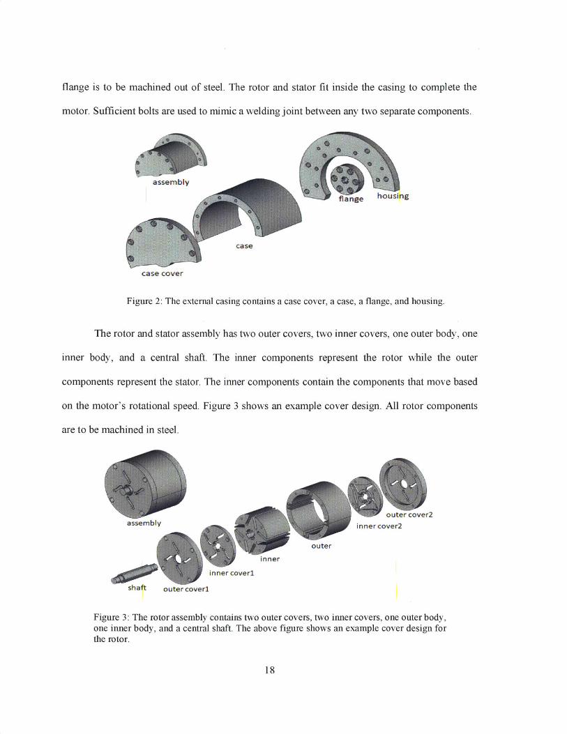
flange is to be machined out of steel. The rotor and stator fit inside the casing to complete the
motor. Sufficient bolts are used to mimic a welding joint between any two separate components.
case cover
Figure 2: The external casing contains a case cover, a case, a flange, and housing.
The rotor and stator assembly has two outer covers, two inner covers, one outer body, one
inner body, and a central shaft. The inner components represent the rotor while the outer
components represent the stator. The inner components contain the components that move based
on the motor's rotational speed. Figure 3 shows an example cover design. All rotor components
are to be machined in steel.
outer cover2assembly Ima ,inner cover2
outer
inner
inner coverl
shaft outer coverl
Figure 3: The rotor assembly contains two outer covers, two inner covers, one outer body,one inner body, and a central shaft. The above figure shows an example cover design forthe rotor.
18

For the rest of the paper, the stator and rotor assembly is flattened and represented in a
diagram similar to that of Figure 4. The dark blue ring in Figure 4 represents the rotor while the
outmost ring represents the stator. Permanent magnets, coils, and magnetic sheet of the rotor are
indicated in the rotor diagram. The motor shaft goes through the hole in the center.
Coil Magnetic Sheet%\ -. NMM.fift /
Figure 4: Basic motor configuration for the rotor designs presented in this paper. The rotorprototypes include permanent magnets, coils surrounding the stator, and a magnetic sheet.U, V, and W indicate the three-phrase coil current.
2.2 Shrinking Diameter Prototype
Conceptual prototypes of the rotor assembly are developed to achieve the two proposed
rotor configurations. The first involves various weighted fins surrounding the rotor. Each fin has
an end cap that constitutes approximately 70 percent of the total fin weight. Due to the skewed
weight distribution along the fin, the centripetal force pulls the heavier end cap outwards,
unfolding the fins and causing them to gravitate towards the shaft of the rotor as it spins, as shown
by the transition between Figure 5(a) and Figure 5(b).
19

(a) (b)
Figure 5: CAD of conceptual prototype of rotor that shrinks at high rotational speeds. (a)shows the "open" fin position, and (b) shows the "closed" fin position, where the finsunfold at high rotational speeds.
The prototype is printed on a Formlabs SLA 3D-printer and tested by press fitting a shaft
and attaching it to the end of a drill that spins at a rate of 1000 RPM. The fins shrink the inner
diameter of the rotor as expected, as shown by the two states in Figure 6.
Figure 6: Conceptual prototype printed on a Formlabs SLA 3D-printer of stator that shrinksat high rotational speeds.
20
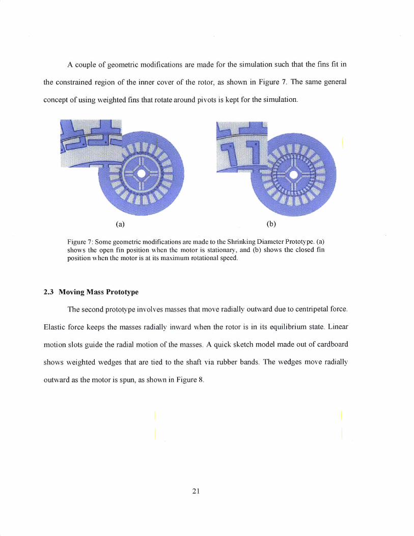
A couple of geometric modifications are made for the simulation such that the fins fit in
the constrained region of the inner cover of the rotor, as shown in Figure 7. The same general
concept of using weighted fins that rotate around pivots is kept for the simulation.
(a) (b)
Figure 7: Some geometric modifications are made to the Shrinking Diameter Prototype. (a)shows the open fin position when the motor is stationary, and (b) shows the closed finposition when the motor is at its maximum rotational speed.
2.3 Moving Mass Prototype
The second prototype involves masses that move radially outward due to centripetal force.
Elastic force keeps the masses radially inward when the rotor is in its equilibrium state. Linear
motion slots guide the radial motion of the masses. A quick sketch model made out of cardboard
shows weighted wedges that are tied to the shaft via rubber bands. The wedges move radially
outward as the motor is spun, as shown in Figure 8.
21

(a) (b)
Figure 8: Sketch model of second prototype made out of cardboard. (a) shows the weightedwedges in its resting state near the shaft, and (b) shows the weighted wedges movingradially outward at its maximum rotational speed.
A couple of modifications were made from the sketch model. The wedges are changed to
rectangular masses (as shown by the red masses in Figure 9) that slide radially outward in guides.
This change is done to ensure easier future fabrication.
(a)
Figure 9: Drawing of rotor with masses (into centripetal force.
(b)
dicated in red) that move radially outward due
22
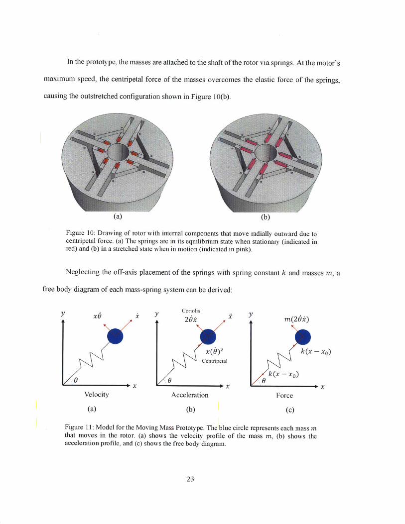
In the prototype, the masses are attached to the shaft of the rotor via springs. At the motor's
maximum speed, the centripetal force of the masses overcomes the elastic force of the springs,
causing the outstretched configuration shown in Figure 10(b).
(a) (b)
Figure 10: Drawing of rotor with internal components that move radially outward due tocentripetal force. (a) The springs are in its equilibrium state when stationary (indicated inred) and (b) in a stretched state when in motion (indicated in pink).
Neglecting the off-axis placement of the springs with spring constant k and masses m, a
free body diagram of each mass-spring system can be derived:
x0 yr
S0
Velocity
(a)
Coriolis
26x
x(b)2
Centripetal
Acceleration
(b)
ym(26k)
k(x - xo)
k(x - xO)
Force
(c)
Figure 11: Model for the Moving Mass Prototype. The blue circle represents each mass mthat moves in the rotor. (a) shows the velocity profile of the mass m, (b) shows theacceleration profile, and (c) shows the free body diagram.
23
y
/f
f

Setting x as the radial distance that the mass travels and 0 as the radial displacement of the mass,
the sum of forces in the radial direction is composed of the spring force and centripetal force and
can be simplified to the following equation:
-k(x - xO) = m(, - x(d)z) (4)
where xO is the initial position of the mass. Similarly, the sum of torques can be simplified to the
following equation:
-2mx,6 = (MR 2 + mx2) 6 (5)
where M is the mass of the rotating disk (i.e. mass of the inner cover of the rotor). Thus, the
equation of motion for the Elastic-Mass system is:
k(x - xo)+X622(t) = -) + x(6)z (6)
6(t) = 4mxO (7)MR 2 + 2mx 2
To find the optimal spring constant at a certain displacement x, the equation of motion is set at
equilibrium (i.e. J = 0) and the spring constant k is isolated:
k = mx (8)x - xo
Since the motor is driven at 0 = 1500 RPM, the mass m is 4.7 g, the length of travel (x - xO) is
30 mm, and the final position of the mass x is 18.5 mm,
Nk = 72.5- (9)m
24

Chapter 3
3. Results and Discussion
Finite element analysis (FEA) of the magnetic flux density of the two proposed prototypes
are conducted and simulation results are presented in the sections below. A final prototype is
fabricated from steel and aluminum by the AW Technical Center and simulation results are
confirmed.
3.1 Governing Equations for FEA
The governing equations for the FEA are derived from Ampere's law and Gauss's law.
One fundamental law of electromagnetism (i.e. Maxwell IV) derived from Ampere's law states
that the curl of the magnetic field H is proportional to the current density 1:
VxH =J (10)
The magnetic vector potential A is a vector field that serves as a potential for the magnetic field
H. From Gauss's law, the curl of the magnetic vector potential is the magnetic flux density B:
VxA = B (11)
The constitutive equation for the magnetic flux density B is the sum of the remanent flux density
Br and the product of the permeability y (refer to Equation (3)) and the magnetic field H:
B = por H + Br (12)
Substituting Equation (11) and (12) into (10), the equation becomes:
VX(CJor)'VXA)=1 + VX((or)'Br) (13)
25

For the two-dimensional case, the x- and y- components of the magnetic vector potential are 0 (i.e.
AX = AY = 0), and the z-component Az is constant. AssumingJ = 0, the governing equations for
the simulation is thus derived:
a 2 Az a 2Az . OBa,, dBr,y+ = (pOP) L - (14) a a2 +a ay ax
where Br,x and Br,y are the x- and y-components of the remanent flux density, respectively.
The magnitude of the magnetic flux density is calculated as follows:
|B| (Bx)2 + (By) 2 (15)
Colors in the simulation results in the following sections correspond to the magnitude of the
magnetic flux density; the more blue-toned the colors are, the smaller the magnitude, and the more
red-toned the colors, the larger the magnitude.
Back EMF E is then calculated by the number of loops N, the thickness of the coils L, the
coil domain f2, and the z-component of the electric field Ez, which is the derivative of A,:
E = NL Ezd.0 = NL az d (16)
3.2 Simulation Results of Shrinking Diameter Prototype
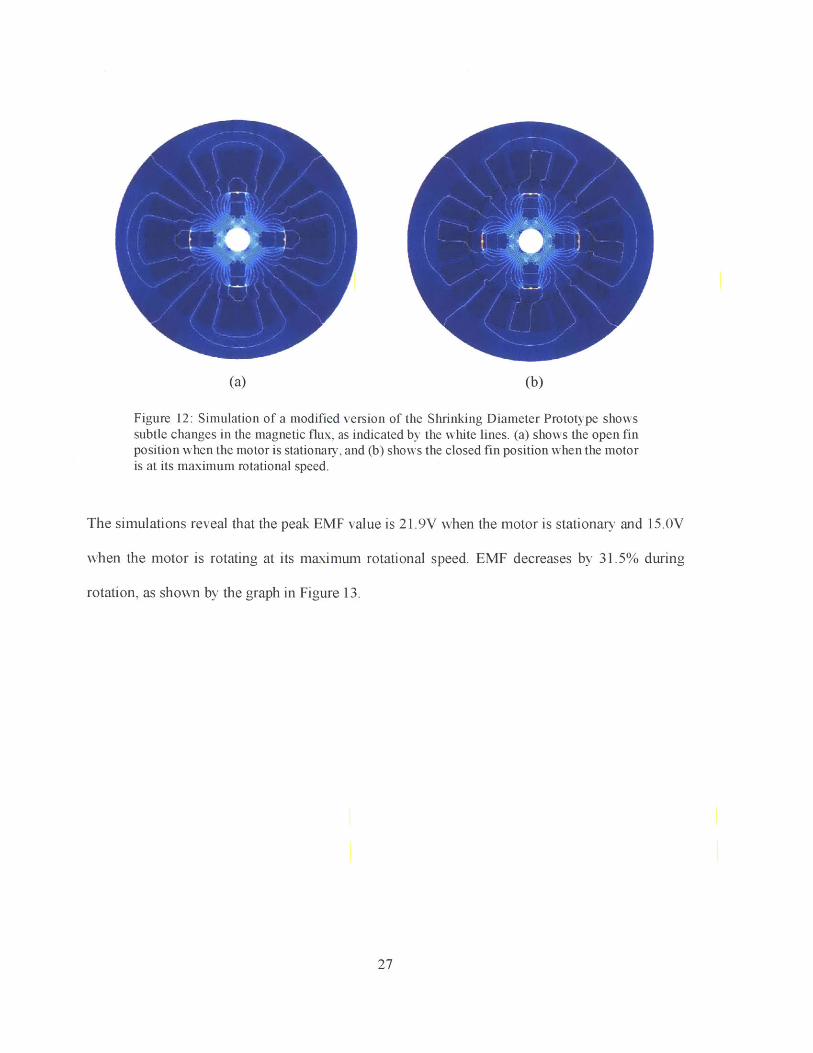
FEA results of the Shrinking Diameter Prototype show the difference in magnetic flux
density when the motor is at rest and when it is spinning. As the rotational speed increases, the fins
of the Shrinking Diameter Prototype rotate and shrink the inner diameter. Small changes in
magnetic field lines are noted near the coils in Figure 12(b).
26
(a) (b)
Figure 12: Simulation of a modified version of the Shrinking Diameter Prototype showssubtle changes in the magnetic flux, as indicated by the white lines. (a) shows the open finposition when the motor is stationary, and (b) shows the closed fin position when the motoris at its maximum rotational speed.
The simulations reveal that the peak EMF value is 21.9V when the motor is stationary and 15.OV
when the motor is rotating at its maximum rotational speed. EMF decreases by 31.5% during
rotation, as shown by the graph in Figure 13.
27
25
20 - stasonary
20
15A [ 1500oRPMJ
10
5
0/
-25
-10
-15
-20
-250 10 20 30 40 50 60 70
Angle (Degrees)
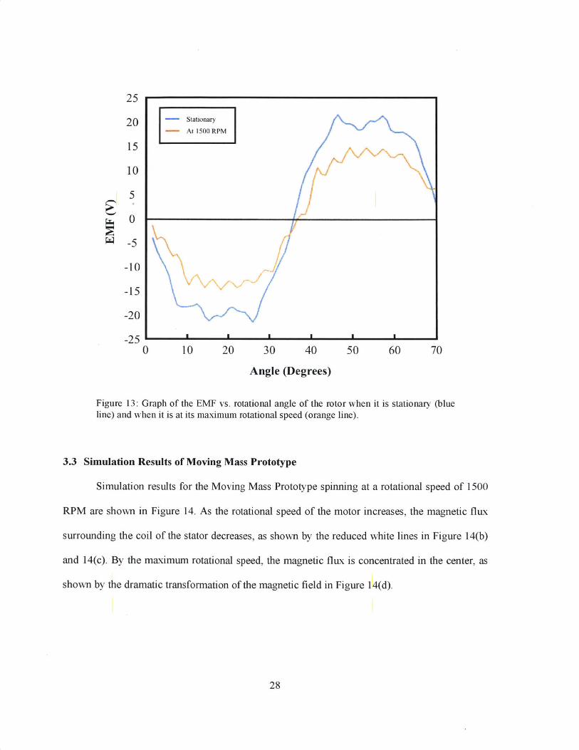
Figure 13: Graph of the EMF vs. rotational angle of the rotor when it is stationary (blueline) and when it is at its maximum rotational speed (orange line).
3.3 Simulation Results of Moving Mass Prototype
Simulation results for the Moving Mass Prototype spinning at a rotational speed of 1500
RPM are shown in Figure 14. As the rotational speed of the motor increases, the magnetic flux
surrounding the coil of the stator decreases, as shown by the reduced white lines in Figure 14(b)
and 14(c). By the maximum rotational speed, the magnetic flux is concentrated in the center, as
shown by the dramatic transformation of the magnetic field in Figure 14(d).
28
(a) (b)
(c) (d)
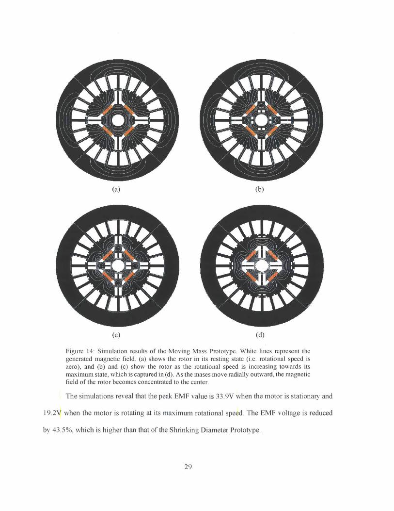
Figure 14: Simulation results of the Moving Mass Prototype. White lines represent thegenerated magnetic field. (a) shows the rotor in its resting state (i.e. rotational speed iszero), and (b) and (c) show the rotor as the rotational speed is increasing towards itsmaximum state, which is captured in (d). As the mases move radially outward, the magneticfield of the rotor becomes concentrated to the center.
The simulations reveal that the peak EMF value is 33.9V when the motor is stationary and
19.2V when the motor is rotating at its maximum rotational speed. The EMF voltage is reduced
by 43.5%, which is higher than that of the Shrinking Diameter Prototype.
29

40 stationary-At 1500 RPM
30
20
10
0
-10
-20
-30
-40S I I I I
0 60 120 180 240 300 360 360
Angle (Degrees)
Figure 15: Graph of the EMF vs. rotational angle of the rotor when it is stationary (blueline) and when it is at its maximum rotational speed (orange line).
3.4 Final Prototype
The Moving Mass Prototype is chosen due to its more promising simulation results. A final
prototype is machined out of steel and aluminum by the AW Technical Center. A couple of
modifications are made to reduce the number of moving components. Unlike the simulation, four
masses are used instead of eight and rubber bands of similar spring constant are used instead of
springs. Machine screws are used as the masses that move radially outward. Parts in the rotor
assembly are made according to Figure 3, and the final rotor assembly is shown in Figure 16.
30

Figure 16: Picture of final rotor assembly, with machine screws used as masses that moveradially outward.
Rubber bands with spring constant of approximately 80 N/m are used as restoring force so
the two desired rotor states can be achieved. Figure 17(a) shows the desired rotor state when the
rotor is stationary, and Figure 17(b) shows the rotor state at its maximum rotational speed of 1500
RPM. At the maximum rotational speed, the centripetal force experienced by the screws
overcomes the elastic force of the rubber bands, causing the screws to translate radially outwards.
All components are made out of steel due to its high magnetic permeability.
31
(a) (b)
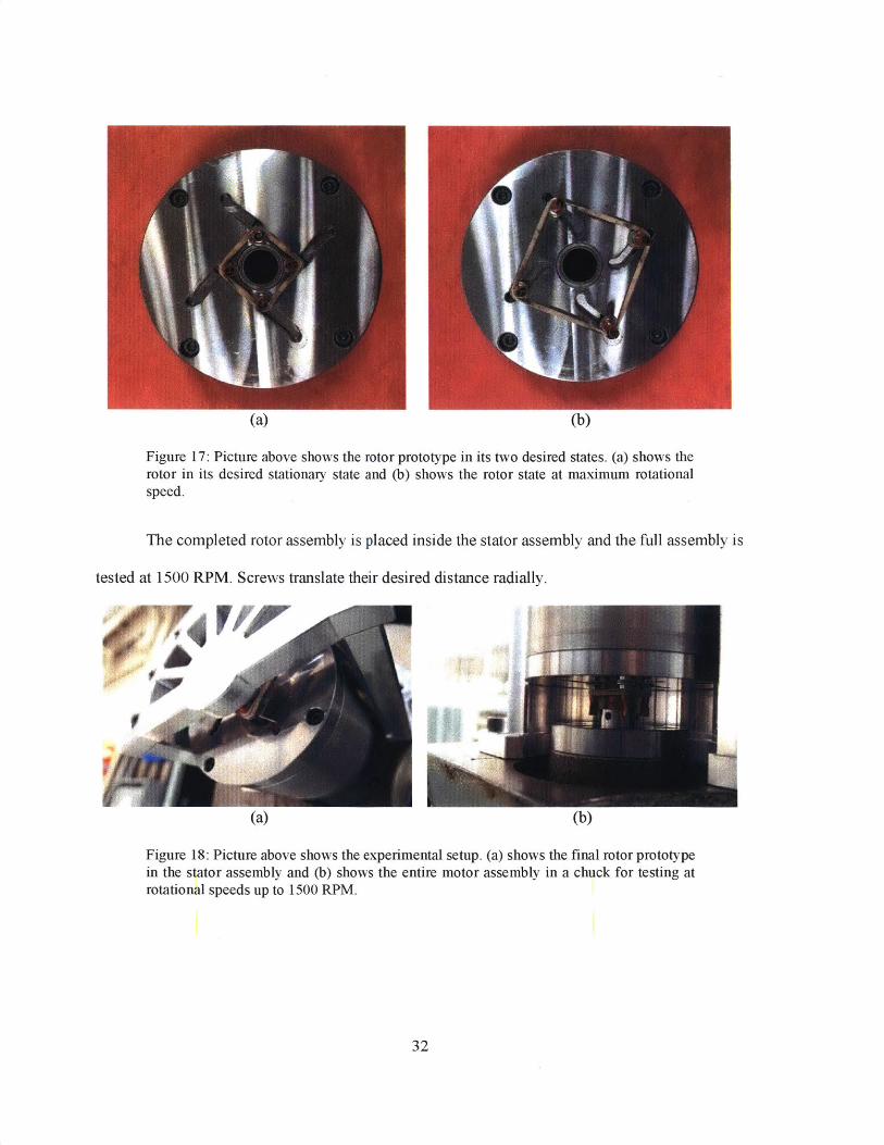
Figure 17: Picture above shows the rotor prototype in its two desired states. (a) shows therotor in its desired stationary state and (b) shows the rotor state at maximum rotationalspeed.
The completed rotor assembly is placed inside the stator assembly and the full assembly is
tested at 1500 RPM. Screws translate their desired distance radially.
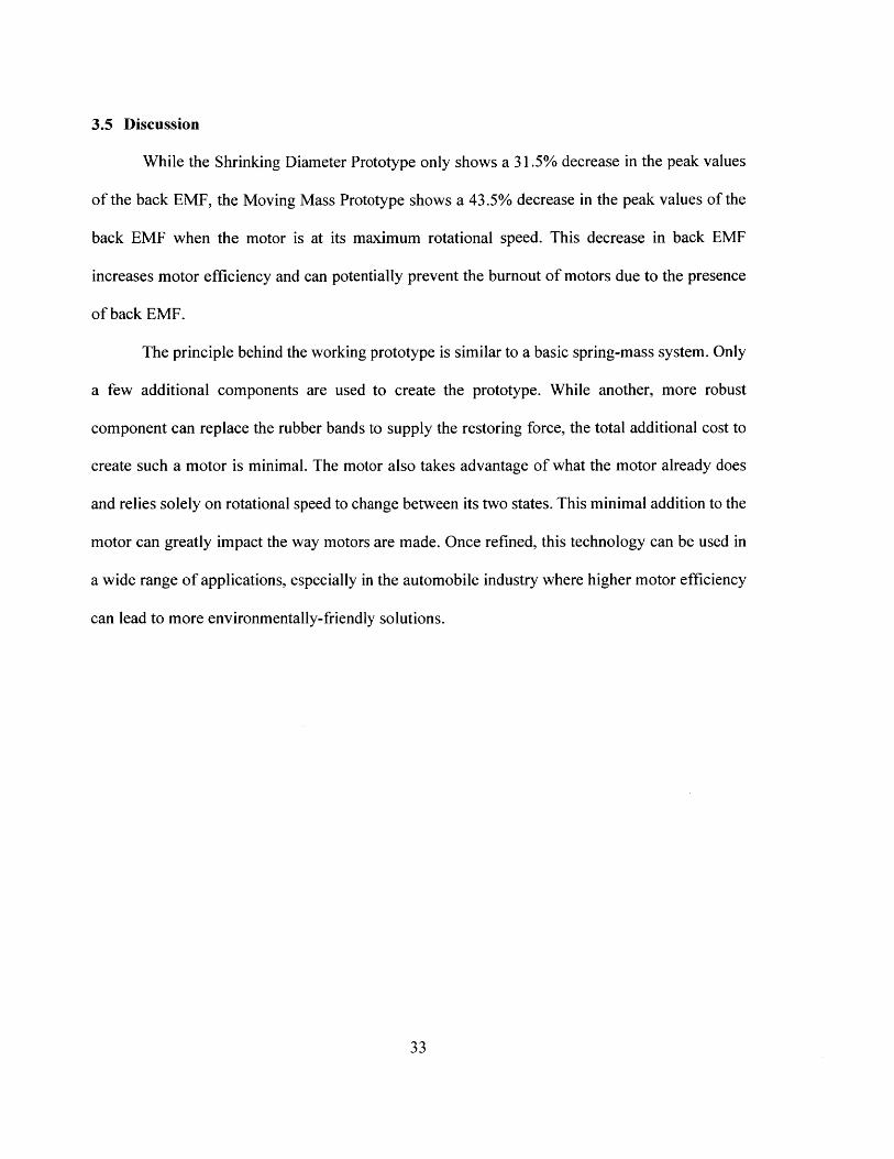
4(a) (b)
Figure 18: Picture above shows the experimental setup. (a) shows the final rotor prototypein the stator assembly and (b) shows the entire motor assembly in a chuck for testing atrotational speeds up to 1500 RPM.
32
4,;00 J. FieAV
J
3.5 Discussion
While the Shrinking Diameter Prototype only shows a 31.5% decrease in the peak values
of the back EMF, the Moving Mass Prototype shows a 43.5% decrease in the peak values of the
back EMF when the motor is at its maximum rotational speed. This decrease in back EMF
increases motor efficiency and can potentially prevent the burnout of motors due to the presence
of back EMF.
The principle behind the working prototype is similar to a basic spring-mass system. Only
a few additional components are used to create the prototype. While another, more robust
component can replace the rubber bands to supply the restoring force, the total additional cost to
create such a motor is minimal. The motor also takes advantage of what the motor already does
and relies solely on rotational speed to change between its two states. This minimal addition to the
motor can greatly impact the way motors are made. Once refined, this technology can be used in
a wide range of applications, especially in the automobile industry where higher motor efficiency
can lead to more environmentally-friendly solutions.
33

Chapter 4
4. Summary
The coils of alternating current (AC) motors experience back electromotive force (EMF)
at high rotational speeds, which acts against applied voltage and drops motor efficiency steeply.
By reducing the magnetic flux surrounding the coil of the stator, motor efficiency can be
maintained at any rotational speed. Taking advantage of centrifugal force and moving motor
components, high overall magnetic permeability is achieved at low rotational speeds, and low
overall magnetic permeability is achieved at high rotational speeds.
Two hypotheses are made in how moving motor components could change the overall
magnetic flux when the motor is in motion. Prototypes are made to challenge the two hypotheses.
The first prototype - the Shrinking Diameter Prototype - utilizes weighted fins that shrink the
inner diameter of the rotor when in motion. The second prototype - the Moving Mass Prototype -
utilizes masses that move radially outward when under rotational motion.
Results from the magnetic flux density simulation of both prototypes show that the Moving
Mass Prototype significantly reduces the magnetic flux surrounding the coil of the stator and
decreases back EMF when under rotational motion. While current motors experience high back
EMF at high rotational speeds, our prototype is able to lower back EMF at high rotational speeds,
increasing the effect of the applied voltage and motor efficiency.
34

Chapter 5
5. Suggestions for Future Work
Several steps can be taken to improve the Moving Mass Prototype. The current final
prototype uses rubber bands to provide the restoring force that brings the motor back to its original
state. Rubber bands will yield after a couple of trials given the repeatability of the moving
components and the high rotational speeds of the motor; another, more robust elastic material
should replace the rubber bands to ensure longevity of the motor.
Because moving components drive the design of the proposed motor, more tests must be
conducted to analyze the motor life cycle. Much higher precision is required in the design to ensure
that the moving components move in the desired path. Some suggestions include adding bearings
to guide the motion, using balls instead of cylinders as the moving component, and adding fillets
to the slots to prevent edge loading.
Additional tests on how changes in magnetic permeability affects motor efficiency must
be done to confirm our findings. While the research presented above proves that magnetic flux is
greatly reduced surrounding the coil of the stator, the research does not show quantitatively that it
increases motor efficiency by a significant amount.
Several other motor concepts besides back EMF reduction were considered in improving
motor efficiency. Another concept that was explored was noise reduction via a structure that
prevents self-resonance. Typically, noise, such as gear noise and power plant bending, is generated
by the resonance vibration of the structure. In an engine, for example, the excitation force causes
transmission in its inner parts, which causes casing vibration and radiation noise, which then
35
transmits to the outside and generates gear noise. By creating an engine that changes states and
controls resonance frequencies depending on input vibration force, noise can be reduced and
efficiency can be increased. Some initial successes have been made in early prototypes where the
structure changes state with different input vibration forces.
36

References
[1] "Stator and Rotor." Learning Engineering, 10 Jan. 2018, www.learningengnr.com/stator-
rotor-difference-stator-rotor/.
[2] "DC Generators." Online Dynamic Enterprise Solutions for Industry Excellence,
www.myodesie.com/wiki/index/retumEntry/id/3033.
[3] Back EMF in Electric Motors. Boston University Department of Physics,
physics.bu.edu/-duffy/sc545_notes04/backemf.html.
[4] "Magnetic Permeability." Encyclopwdia Britannica, Encyclopedia Britannica, Inc., 25 Oct.
2016, www.britannica.com/science/magnetic-permeabilitv.
[5] "Magnetic constant". Fundamental Physical Constants. Committee on Data for Science and
Technology. 2006. National Institute of Standards and Technology.
[6] Permeability: Electromagnetism and Formation of Magnetic Fields. Engineering Toolbox,
www.engineeringtoolbox.com/permeability-d 1923.html.
[7] Back EMF Suppression. Progeny Access Control, progeny.co.uk/back-emf-suppression/.
[8] Kang, Seog-Joo, and Seung-Ki Sul. "Direct Torque Control of Brushless DC Motor with
Nonideal Trapezoidal Back EMF." IEEE Transactions on Power Electronics, vol. 10, no. 5,
Nov. 1995, pp. 796-802., doi:10.1109/63.471301.[9] Zhong, L., and M.F. Rahman. "Analysis of Direct Torque Control in Permanent Magnet
Synchronous Motor Drives." IEEE Transactions on Power Electronics, vol. 12, no. 3, May
1997, pp. 528-536., doi:10.1109/63.575680.[10] "Improved Direct Back EMF Detection for Sensorless Brushless DC (BLDC) Motor
Drives." Applied Power Electronics Conference and Exposition, 2003,doi:10.1 109/APEC.2003.1179230.
[11] Collins, Danielle. "What Is Sinusoidal Back EMF with Sinusoidal Current?"Motion Control
Tips, 23 Apr. 2016, www.motioncontroltips.com/faq-sinusoidal-emf-sinusoidal-current/.
37