rotation 3200 hp, n = 2000 rpm 2.5 in. - encsnrskumar/index_files...known: a rectangular beam has an...
TRANSCRIPT

4-24
SOLUTION (4.18) Known: A steel propeller shaft with a given diameter transmits a known power at a specified angular velocity. Find: (a) Determine the nominal shear stress at the surface. (b) Determine the outside diameter required to give the same outer surface stress if a
hollow shaft of inside diameter 0.85 times the outside diameter is used. (c) Compare the weights of the solid and hollow shafts. Schematic and Given Data:
2.5 in.3200 hp, n = 2000 rpm
Rotation
dido d
Assumptions: 1. Bending and axial loads are negligible. 2. The bar is straight and round. 3. The material is homogeneous, and perfectly elastic within the stress range
involved. 4. The effect of stress raisers is negligible. Analysis: 1. From Eq. (1.3), T = 5252 W
n
T = 5252(3200)
2000 = 8403 lb ft = 100,838 lb in.
2. From Eq. (4.4), ! = 16 T" d3
! =
16 (100,838)" (2.5)3
= 32,868 psi = 33 ksi ■
4-25
3. For a hollow shaft, do3 - (0.85)4 do3 = 2.53 0.478 do3 = 15.625 do = 3.20 in. ■
4. Wt. hollowWt. solid
= Area hollowArea solid
= 3.202 - (0.85 ! 3.20)2
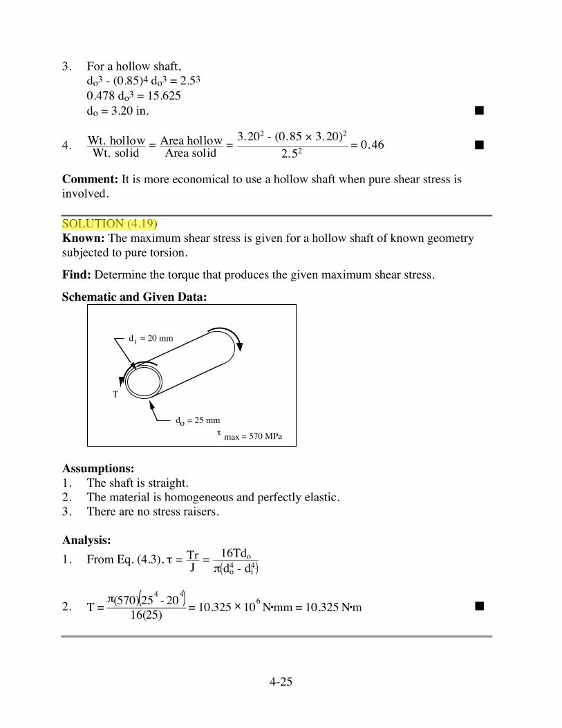
2.52 = 0.46 ■ Comment: It is more economical to use a hollow shaft when pure shear stress is involved. SOLUTION (4.19) Known: The maximum shear stress is given for a hollow shaft of known geometry subjected to pure torsion.
Find: Determine the torque that produces the given maximum shear stress.
Schematic and Given Data:
T
! max = 570 MPa
do = 25 mm
d = 20 mmi
Assumptions: 1. The shaft is straight. 2. The material is homogeneous and perfectly elastic. 3. There are no stress raisers. Analysis: 1. From Eq. (4.3), ! = Tr
J = 16Tdo" do
4 - di4
2. T =!(570)254 - 204
16(25) = 10.325 " 106N•mm = 10,325 N•m ■

4-26
SOLUTION (4.20) Known: The same value of torque is applied to both a solid square shaft (b ✕ b) and a solid round shaft of radius r. Find: (a) Determine the ratio b/r for both square and round shafts so as to produce equal
maximum shear values. (b) Compare the weight of the two shafts for the square and round shafts. (c) Compare the ratio of strength-to-weight for the square and round shafts. Schematic and Given Data:
T
2r
T
b
TT
Assumptions: 1. The shafts are straight. 2. The material is homogeneous and perfectly elastic. 3. There are no stress raisers. 4. The shafts are made of the same material. Analysis: 1. For equal stress, equate Eq. (4.4) with Eq. (4.5).
16 T!(2r)3 = 4.8 T
b3
16 b3
8!r3 = 4.8 b
r3 = 7.5398
b
r = 1.96 ■

4-27
2. Wt. square per unit length
Wt. round per unit length = b2
!r2 = b2
! b1.96
2 = 1.22 ■
3. (Strength/wt. )square(Strength/wt. )round
= T/WsT/Wr
= WrWs
= 11.22
= 0.82 ■
Comment: The round bar is more economical (higher strength to weight ratio) than the square bar for the same shear stress.

4-28
SOLUTION (4.21) Known: The maximum shear stress produced in a shaft transmitting torque is given. Find: Determine the torque: (a) In a round shaft of 40 mm diameter. (b) In a square shaft, 40 mm on a side. Schematic and Given Data:
T
dia. = 40 mm
T
40 mm
!max = 400 MPa
Assumptions: 1. The shafts are straight. 2. The material is homogeneous and perfectly elastic. 3. There are no stress raisers. Analysis: 1. From Eq. (4.4), ! = 16T
"d3
T = (400)(!)(40)3
16 = 5.03 " 106 N•mm = 5030 N•m ■ 2. From Eq. (4.5), τ = 4.8T
a3
T = 400(40)3
4.8 = 5.33 ! 106 N•mm = 5330 N•m ■

4-29
SOLUTION (4.22) Known: The geometries of a solid round shaft and a solid square shaft of the same size (circle diameter equal to side of square) are given. Find: Compare the torque transmitting strength, the weight, and the ratio of strength to weight of the two shafts. Schematic and Given Data:
T
d
T
d
Assumptions: 1. The shafts are straight. 2. The material is homogeneous and perfectly elastic. 3. There are no stress raisers. 4. The shafts are made of the same material. Analysis: 1. For equal stress, equate Eq. (4.14) with Eq. (4.5).
16 Tround
!d3 = 4.8 Tsquare
d3
T square = Tround 164.8!
= 1.061 Tround ■ 2. Wt. square per unit length
Wt. round per unit length = d2
!4
d2 = 4! = 1.273 ■
3. (Strength/wt. )square(Strength/wt. )round
= 1.0611.273
= 0.833 ■
Comment: The round bar is more economical (higher strength to weight ratio) than the square bar for the same shear stress.

4-43
SOLUTION (4.33) Known: A rectangular beam has an initial curvature, r, equal to twice the section depth, h. Find: Compare its extreme-fiber bending stresses with those of an otherwise identical straight beam. Schematic and Given Data:
h
b
M M
r
Assumption: The material is homogeneous and perfectly elastic. Analysis:
1. For a straight beam, from Eq. (4.7) where Z = bh2
6 (From Appendix B-1).
!i = - 6M
bh2 ; !o = + 6Mbh2
2. For a curved beam, from Eq. (4.10)
e = r - A
dA/! = 2h - bh
b d!/!ri
ro
= 2h - h
ln rori
= 2h - hln 2.5h
1.5h
= 2h - h
ln(5 3) = .042385 h
3. From Eq. (4.9),

4-44
σ i =
ΜcieAri
= M(0.5h - .042385h)(.042385h)(bh)(1.5h) =
7.1978Mbh2
But for direction of "M" shown, σ i = -7.20M
bh2
!o = M(0.5h + .042385h)
(.042385h)(bh)(2.5h) = - 5.119M
bh2 But for direction shown of M: !o = +5.20M
bh2 4. From Eq. (4.11), with Z = bh2/6:
Ki = 7.19786
= 1.20 and Ko = 5.1196
= 0.85 which is consistent with Fig. 4.11. 5. The inner and outer fiber bending stresses for the curved beam are 120% and
85% of the straight beam stresses. ■

4-45
SOLUTION (4.34) Known: A known force is exerted on an S-hook. Find: Determine the location and magnitude of the maximum tensile stress. Schematic and Given Data:
3 in.
4 in.
200 lb
200 lb
1 in. dia. round rod
Assumption: Material is homogeneous and perfectly elastic. Analysis: 1. At point A, the tensile stress due to bending is ! = 32M
"d3 Kt [From Eq. (4.11)] The tensile stress due to tension is ! = P
A = 4P"d2 [From Eq. (4.1)]
200 lb
200 lb
600 in. lb
r = 3 in.
A
4-46
Thus, the combined tensile stress is
! = 32M
"d3 Kt + 4P"d2
2. From Fig. 4.11, for r
c = 30.5 = 6, Kt = 1.14.
3. ! = (1.14) 32(600)
"(1)3 + 4(200)"(1)2 = 6,967 + 255
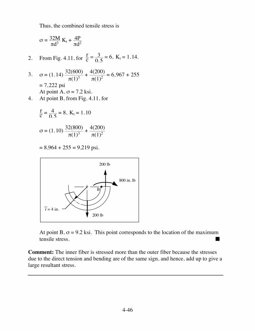
= 7,222 psi At point A, σ = 7.2 ksi. 4. At point B, from Fig. 4.11, for
rc = 4
0.5 = 8, Kt = 1.10
! = (1.10) 32(800)"(1)3 + 4(200)
"(1)2
= 8,964 + 255 = 9,219 psi.
200 lb
200 lb
800 in. lb
r = 4 in.
B
At point B, σ = 9.2 ksi. This point corresponds to the location of the maximum tensile stress. ■
Comment: The inner fiber is stressed more than the outer fiber because the stresses due to the direct tension and bending are of the same sign, and hence, add up to give a large resultant stress.

4-49
SOLUTION (4.36) Known: The critical section of a crane hook is considered to be trapezoidal with dimensions as shown. Find: Determine the resultant stress (bending plus direct tension) at points P and Q. Schematic and Given Data:
40
120
80
70,000 N
A A
P Q60
Assumption: Material is homogeneous and perfectly elastic. Analysis: 1.
40
120
80
= +
c c c
40 40
c (rectangle) = 60, c (triangle) = 40

4-50
c (trapezoid) = Ac (rectangle) + Ac(triangle)
A(trapezoid)
= 4800(60) + 2400(40)60(120) = 53.33
2. I of trapezoid about its centroidal axis = I of rectangle + I of triangle, each about
the centroidal axis of trapezoid. Using the parallel axis theorem and equations from Appendix B-1:
I(trapezoid) = 40(120)
3
12 + 4800(60 - 53.33)2
+ 40(120)3
36 + 2400(40 - 53.33)2
= 5.76 ! 106 + .213 ! 106 + 1.92 ! 106 + .426 ! 106 = 8.32 ! 106 mm4 3. r
c(trapezoid) = 60 + 53.3353.33
= 2.13. From Fig. 4.11, Ki = 1.52, Ko = 0.73. 4. The tensile stress due to tension is ! = PA [From Eq. 4.1)] and tensile stress due to bending is ! = KMc
I [From Eq. (4.11)].
5. At P, the resultant stress is ! = P
A - Ko Mc
I
= 70,000N7200 mm2 - (0.73)
[70,000(60 + 53.33)N•mm](66.67 mm)8.32 ! 106 mm4
= 9.72 MPa - 46.41 MPa = -36.69 MPa ■ 6. At Q, the resultant stress is ! = P
A + Ki McI

4-51
= 9.72 MPa + (1.52)
[70,000(113.33)N•mm](53.33 mm)8.32 ! 106 mm4
= 9.72 MPa + 77.29 MPa = 87.01 MPa ■ SOLUTION (4.37) Known: The critical section of a crane hook is considered to be circular with areas as shown. Find: Determine the resultant stress (bending plus direct tension) at points P and Q. Schematic and Given Data:
70,000 N
A A
P Q60
A = 7,200 mm2
Assumption: The material is homogeneous and perfectly elastic. Analysis: 1. c = d2 = 4A/!
2 = A/! = 7200/! = 47.87 = 48 mm
2. I = !d4
64 = ! 96 4
64 = 4.17 " 106 mm4 3. r
c (circle) = 60 + 4848 = 2.25. From Fig. 4.11, Ki = 1.50, Ko = 0.75

4-52
4. The tensile stress due to tension is
! = PA [From Eq. 4.1)] and tensile stress due to bending is ! = KMc
I [From Eq. (4.11)].
5. At P, the resultant stress is
! = PA
- Ko McI
= 70,000N
7200 mm2 - (0.75) [70,000(60 + 48)N•mm](48 mm)4.17 ! 106 mm4
= 9.72 MPa - 65.27 MPa = -55.55 MPa ■ 6. At Q, the resultant stress is
! = PA + Ki Mc
I
= 9.72 MPa + (1.50) [70,000(108)N•mm](48 mm)
4.17 ! 106 mm4
= 9.72 MPa + 130.53 MPa = 140.25 MPa ■ Comment: By comparing the resultant stresses in Solutions 4.21 and 4.22, it is evident that for the same area of cross section the trapezoidal section is stronger and hence, more economical than a circular cross section crane hook. This is the reason, for the use of trapezoidal shaped cross sections in crane hooks for practical applications.

4-60
SOLUTION (4.44) Known: An I-beam with given dimensions is simply supported at each end and subjected to a know load at the center. Find: Compute the maximum transverse shear stress. Compare the answer with the approximation obtained by dividing the shear load by the area of the web, with the web considered to extend for the full 8-in. depth. Schematic and Given Data:
8 in.
500 lb 500 lb
1000 lb
3 12 in.
3 12 in. 1
2 in.
12 in.
38 in.
Assumption: The beam material is homogeneous and perfectly elastic. Analysis: 1. τmax exists at the neutral bending axis,
! = V
Ib ydA [Eq. (4.12)]
2.
8
3.5 3.125
8= -
3.5
72
1

4-61
From the above figure,
I = I1 - I2 =3.5(8)3
12 - 3.125(7)3
12 = 60.01 in. 4
3. !max = 500(60.01) (0.375)
y(0.375dy)0
3.5
+ y(3.5dy)3.5
4
= 22.22 0.375 3.52
2 + 3.5 42
2 - 3.52
2 = 197 psi ■ 4. To check,
!max " 500(38
)(8) = 167 psi ■
Comment: The rough check is 15% low in this case. SOLUTION (4.45) Known: A box section beam, where the top plate of the section is cemented in place, is loaded with a specified force. Find: Determine the shear stress acting on the cemented joint. Schematic and Given Data:
12 kN
50 mm5
5
5
5
40 mm
CementL2
L2

4-62
50 mm5
5
5
5
40 mm
=
40
50
-
30
40
1 2
Assumption: The beam material is homogeneous and perfectly elastic. Analysis:
1. From Eq. (4.12), ! = VIb ydA
y = 20
y = 25
2. From the above figure, I = I1 - I2
= (40)(50)
3
12 - (30)(40)3
12 = 256,667 mm4
3. ! = 6000(256,667)(10) y(40dy)
20
25
= 6000(40)2,566,670 y
2
2 20
25
= 10.5 MPa ■ SOLUTION (4.46) Known: A shaft between self-aligning bearings A and B is loaded through belt forces applied to a central sheave. Find: (a) Determine and make a sketch showing the stresses acting on the top and side
elements, T and S. (b) Represent the states of stress at T and S with three-dimensional Mohr circles. (c) At location S, show the orientation and stresses acting on a principal element,
and on a maximum shear element.

4-63
Schematic and Given Data:
2000 N
400 N
100 mm
100 mm
A
B
20 mm dia.shaft
Connected toflexible couplingand clutch
Freeend ofshaft
TS
120 mm dia.sheave
1200 N
-1200 N
120,000 N•mmM
V
T 96,000 N•mm
TA
1200 N 2400 N1200 N
B
Assumptions: 1. The weights of the shaft and sheave are negligible.

4-64
2. The shaft is straight. 3. The effect of stress concentrations is negligible. 4. The shaft material is homogeneous and perfectly elastic. Analysis: 1. For torsion, Eq. (4.4),
! = 16T
"d3 = 16(1600)(60)"(20)3 = 61.12 MPa
2. For bending, Eq. (4.8),
! = 32M
"d3 = 32(1200)(100)"(20)3 = 152.79 MPa
3. For transverse shear, Eq. (4.13),
! = 43 VA = 4(1200)
3(")(10)2 = 5.09 MPa
4. T xy
! = 66.21 MPa
S xy
! = 61.12 MPa
152.79 MPa
5.
S"
!x (153,61)
y (0,-61)
0
!max
38.66o
"1
x (0,66)
T
y (0,-66)
0 "
1"
!
S xy
Original Element
Principal
"1 = +174
2" = -21
19.3o
S
6.
Max Shear
"= 77
!= 98
25.7 o
S61.1
153
51.4˚

4-70
SOLUTION (4.49) Known: A static vertical load is applied to the handle of a hand crank. Find: (a) Copy the drawing and mark on it the location at highest bending stress. Make a
three-dimensional Mohr-circle representation of the stresses at this point. (b) Mark on the drawing the location at highest combined torsional and transverse
shear stress. Make a three-dimensional Mohr-circle representation of the stresses at this point.
Schematic and Given Data:
200 mm
250 mm
100 mm1000 N
25-mm-dia.round rodbent into crank
a
a b
Assumptions: 1. The weight of the hand crank is negligible. 2. The effect of the stress concentration is negligible. 3. The crank material is homogeneous and perfectly elastic. Analysis: 1. For bending, Eq. (4.8)
! = 32M
"d3 = 32(300 mm)(1000 N)"(25 mm)3 = 195.6 MPa
2. For torsion, Eq. (4.4)
! = 16T
"d3 = 16(250 mm)(1000 N)"(25 mm)3 = 81.5 MPa
4-71
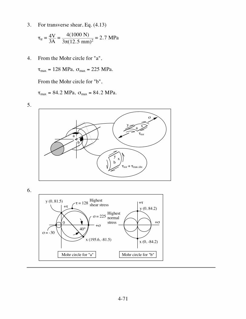
3. For transverse shear, Eq. (4.13)
!tr = 4V
3A = 4(1000 N)3"(12.5 mm)2 = 2.7 MPa
4. From the Mohr circle for "a",
!max = 128 "Pa, #max = 225 "Pa. From the Mohr circle for "b",
!max = 84.2 "Pa, #max = 84.2 "Pa. 5.
bxy
!tor + !tran.shr.
y xa!tor
"
ab
6.
040°
x (195.6, -81.5)
y (0, 81.5)
! = -30
! = 225
+!
+"" = 128 Highest
shear stress
Highest normalstress
Mohr circle for "a" Mohr circle for "b"
x (0, -84.2)
+!
+"y (0, 84.2)

4-74
SOLUTION (4.51) Known: An electric motor is loaded by a belt drive. Find: Copy the drawing and show on both views the location or locations on the shaft of the highest stress. Make a complete Mohr-circle representation of the stress at this location. Schematic and Given Data:
1 in.
Motor
1000 lbbelt tension
3000 lbbelt tension
1 in. dia. shaft
6 in. dia.
Assumptions: 1. The weight of the structure is negligible. 2. The effect of stress concentration is negligible. 3. The shaft material is homogeneous and perfectly elastic. Analysis: 1. For torsion, Eq. (4.4)
! = 16T
"d3 = 16(2000 lb)(3 in. )"(1 in. )3 = 31 ksi
2. For bending, Eq. (4.8)
! = 32M
"d3 = 32(4000 lb)(1 in. )"(1 in. )3 = 41 ksi
3. The Mohr circle representation is given above.
4-75
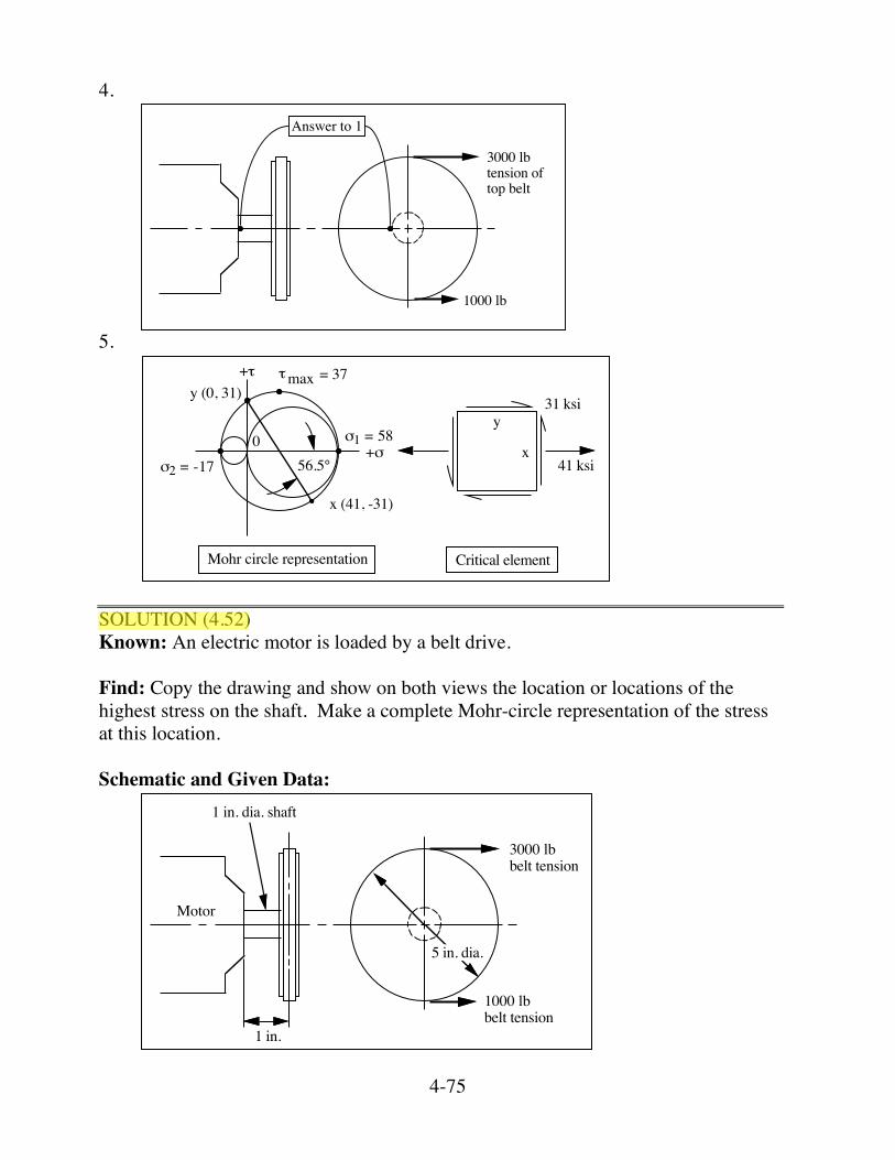
4.
1000 lb
3000 lbtension of top belt
Answer to 1
5.
056.5°
x (41, -31)
y (0, 31)
+!
+"
31 ksi
41 ksi
y
x
Mohr circle representation Critical element
"max = 37
!1 = 58
!2 = -17
SOLUTION (4.52) Known: An electric motor is loaded by a belt drive. Find: Copy the drawing and show on both views the location or locations of the highest stress on the shaft. Make a complete Mohr-circle representation of the stress at this location. Schematic and Given Data:
1 in.
Motor
1000 lbbelt tension
3000 lbbelt tension
1 in. dia. shaft
5 in. dia.

4-76
Assumptions: 1. The weight of the structure is negligible. 2. The effect of stress concentration is negligible. 3. The shaft material is homogeneous and perfectly elastic. Analysis: 1. For torsion, Eq. (4.4)
! = 16T
"d3 = 16(2000 lb)(2.5 in. )"(1 in. )3 = 25 ksi
2. For bending, Eq. (4.8)
! = 32M
"d3 = 32(4000 lb)(1 in. )"(1 in. )3 = 41 ksi
3. The Mohr circle representation is given below. 4.
1000 lb
3000 lbtension of top belt
Answer to 1
5.
050.7°
x (41,-25)
y (0, 25)
+!
+"
25 ksi
41 ksi
y
x
Mohr circle representation Critical element
"max = 32
!1 = 53
!2 = -12

4-77
SOLUTION (4.53) Known: A solid round shaft with a known diameter is supported by self-aligning bearings at A and B. Two chain sprockets that are transmitting a load are attached to the shaft. Find: Identify the specific shaft location subjected to the most severe state of stress, and make a Mohr-circle representation of this stress state. Schematic and Given Data:
500 lb
1000 lb
4 in.
2 in.
3 in.
3 in.
4 in.
A
B1 in. dia. shaft
Assumptions: 1. The loads are static. 2. Stress concentrations can be ignored. 3. The shaft is straight. 4. The shaft material is homogeneous and perfectly elastic.

4-78
Analysis: 1.
3 in.3 in. 4 in.
A B850 lb
1000 lb500 lb650 lb
V650 lb
150 lb
- 850 lbMmax = 850 lb(3 in.) = 2550 in.lb
M
!MA = 0 1000(7) + 500(3) = FB(10) FB = 8500/10 = 850 lb [ ]!Fv = 0 FA = 500 + 1000 - 850 = 650 lb 2.
A
BBottom of shaft; just to left of gear
4-79
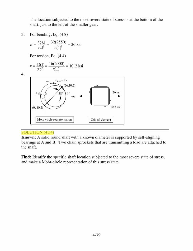
The location subjected to the most severe state of stress is at the bottom of the shaft, just to the left of the smaller gear.
3. For bending, Eq. (4.8)
! = 32M
"d3 = 32(2550)" 1 3 = 26 ksi
For torsion, Eq. (4.4)
! = 16T
"d3 = 16(2000)" 1 3 = 10.2 ksi
4.
0 +!
+"
26 ksi
10.2 ksi
Mohr circle representation Critical element
38°
(26,10.2)
(0,-10.2)
30-3.5
"max = 17
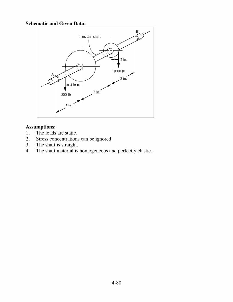
SOLUTION (4.54) Known: A solid round shaft with a known diameter is supported by self-aligning bearings at A and B. Two chain sprockets that are transmitting a load are attached to the shaft. Find: Identify the specific shaft location subjected to the most severe state of stress, and make a Mohr-circle representation of this stress state.
4-80
Schematic and Given Data:
500 lb
1000 lb
4 in.
2 in.
3 in.
3 in.
3 in.
A
B1 in. dia. shaft
Assumptions: 1. The loads are static. 2. Stress concentrations can be ignored. 3. The shaft is straight. 4. The shaft material is homogeneous and perfectly elastic.
4-81
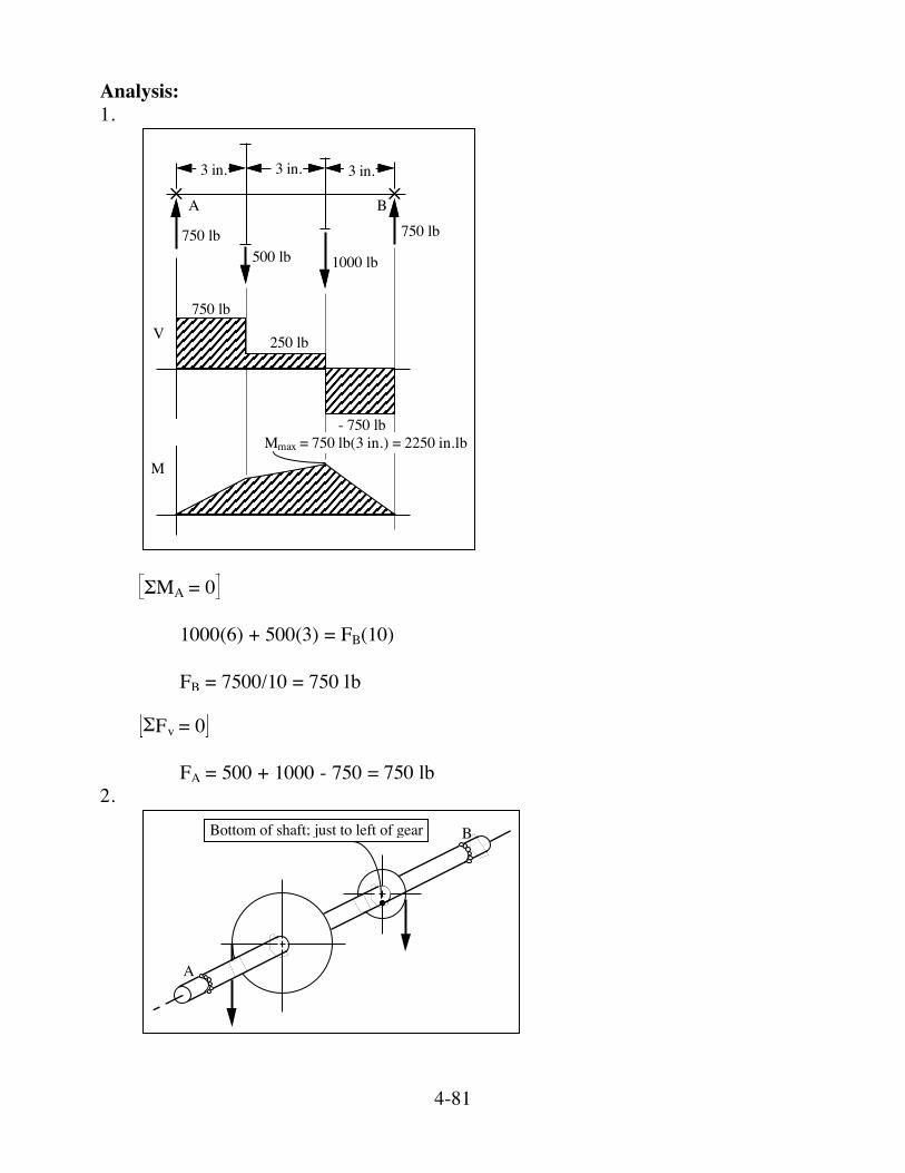
Analysis: 1.
3 in.3 in. 3 in.
A B750 lb
1000 lb500 lb750 lb
V750 lb
250 lb
- 750 lbMmax = 750 lb(3 in.) = 2250 in.lb
M
!MA = 0 1000(6) + 500(3) = FB(10) FB = 7500/10 = 750 lb [ ]!Fv = 0 FA = 500 + 1000 - 750 = 750 lb 2.
A
BBottom of shaft; just to left of gear
4-82
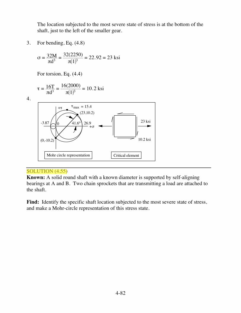
The location subjected to the most severe state of stress is at the bottom of the shaft, just to the left of the smaller gear.
3. For bending, Eq. (4.8)
! = 32M
"d3 = 32(2250)" 1 3 = 22.92 = 23 ksi
For torsion, Eq. (4.4)
! = 16T
"d3 = 16(2000)" 1 3 = 10.2 ksi
4.
0 +!
+"
23 ksi
10.2 ksi
Mohr circle representation Critical element
41.6°
(23,10.2)
(0,-10.2)
26.9-3.87
= 15.4"max
SOLUTION (4.55) Known: A solid round shaft with a known diameter is supported by self-aligning bearings at A and B. Two chain sprockets that are transmitting a load are attached to the shaft. Find: Identify the specific shaft location subjected to the most severe state of stress, and make a Mohr-circle representation of this stress state.

4-83
Schematic and Given Data:
A
B
50 mm
50 mm
100 mm
4000 N
30 mm dia.
50 mm dia.
F
100 mm dia.
Assumptions: 1. The loads are static. 2. Stress concentration can be ignored. 3. The shaft is straight. 4. The shaft material is homogeneous and perfectly elastic. Analysis: 1.
A
B
4000 N
Front view
Top view
3000 N
500 N
1000 N
1500 NFg = 2000 N
C
D

4-84
2.
A B C D A B C D
500 N
2000 N1500 N
1000 N4000 N3000 N
T T100 N•m 100 N•m
150 N•m
-75 N•m
3000 N
-1000 N -500 N
1500 N
Front view Top view
V V
MM
3. The most severe state of stress is at B
M = [ ](3000)(50) 2 + [ ](500)(50) 2 = 152,069 N•mm T = 4000 (25) = 100,000 N•mm 4. For bending, Eq. (4.8)
! = 32M
"d3 = 32(152,069)"(30)3 = 57.4 MPa
! = 16T
"d3 = 16(100,000)"(30)3 = 18.9 MPa

4-85
5.
033°
+!
+"
57.4
18.9
(57.4,-18.9)
(0,18.9)
!1 = 63 MPa
"max = 34.3 MPa
= -5.7!2
Mohr circle representation of point B SOLUTION (4.56) Known: A small pressurized cylinder is attached at one end and loaded with a pipe wrench at the other. The stresses due to the internal pressure and the pipe wrench are known. Find: (a) Draw a Mohr-circle representation of the state of stress at point A. (b) Determine the magnitude of the maximum shear stress at A. (c) Sketch the orientation of a principal element, and show all stresses acting on it. Schematic and Given Data:
A
400 MPa
300 MPa
200 MPa

4-86
Assumption: The "positive-clockwise" rule is used. Analysis: 1.
x
y
103°
!max = 278 MPa+!
+""1 = 556 MPa
"2 = 144 MPa
"30300 400
2. The maximum shear stress at A is !max = 278 MPa ■ 3.
51.5°
A
!1
!2
!2 = 144 MPa
!1 = 556 MPa
!3 = 0
SOLUTION (4.57) Known: A small pressurized cylinder is attached at one end and loaded with a pipe wrench at the other. The stresses due to the internal pressure and the pipe wrench are known. Find: (a) Draw a Mohr-circle representation of the state of stress at point A. (b) Determine the magnitude of the maximum shear stress at A. (c) Sketch the orientation of a principal element, and show all stresses acting on it.
4-87
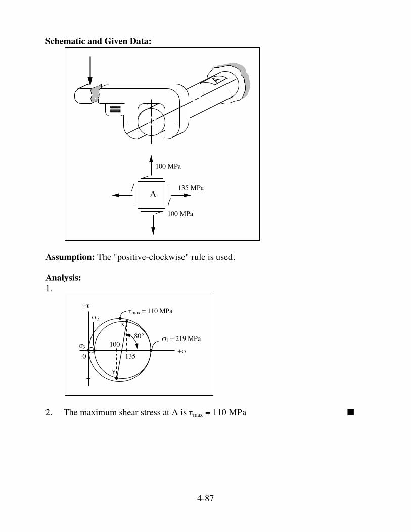
Schematic and Given Data:
A
100 MPa
135 MPa
100 MPa
Assumption: The "positive-clockwise" rule is used. Analysis: 1.
x
y
80°
!max = 110 MPa+!
+"
"1 = 219 MPa
"2
"3
0
100
135
2. The maximum shear stress at A is !max = 110 MPa ■

4-88
3.
40°
A
!1
!2
!2 = 16
!1 = 219 MPa
!3 = 0
MPa
Comment: At the outer surface of an internally pressurized cylinder, the tangential stress is analytically twice the axial stress. That is, the axial stress for a thick walled cylinder is !a = piri2
ro2 - ri2 and the tangential stress is !t = 2piri2
ro2 - ri2. Therefore, !t
!a = 2.
We could speculate in this problem that a stress concentration existed which increased the axial stress from 50 MPa to 60 MPa.

4-111
SOLUTION (4.77) Known: A stepped shaft with known dimensions is supported by bearings and carries a known load. Find: Determine the maximum stress at the shaft fillet. Schematic and Given Data:
A B
1000 N
500 mm 250 mm
r = 5 mmd = 40 mm
RA
RB
70 mm

4-112
AB
667 N
1000 N333 N
333 N
-667 N
V
M
C
D E F
G 47 N•m
500 mm
70 mm
250 mm
168 N•m
Assumptions: 1. The shaft remains straight . 2. The material is homogeneous and perfectly elastic. Analysis: 1. Σ MB = 0 : Hence RA = 333 N Σ FY = 0 : RA + RB = 1000, Therefore RB = 667 N 2. From similar triangle, ΔCDF and ΔGEF, GE = 47 N•m. The stress due to bending at the critical shaft fillet is equal to
!nom = 32M
"d3 = 32(47)"(0.04)3 = 7.5 MPa.
3. r/d for the critical shaft fillet = 5/40 = 0.125 D/d = 80/40 = 2 From Fig. (4.35a), Kt = 1.65 Therefore, σmax = σnom Kt = 7.5(1.65) = 12.4 MPa

4-127
SOLUTION (4.88) Known: Three notched tensile bars (see Fig. 4.39) have stress-concentrations of 1, 1.5 and 2.5 respectively. Each is made of ductile steel and have Sy = 100 ksi, a rectangular cross-section with a minimum area of 1 in.2, and is initially free of residual stress. Find: Draw the shape of the stress-distribution curve for each case when (a) A tensile load of 50,000 lb is applied. (b) The load is increased to 100,000 lb. (c) The load is removed. Schematic and Given Data:
A = 1 in.2
PP
Sy = 100 ksi
Analysis:
K = 1 K = 1.5 K = 2.550
50
75
50
100
100100100
-50 -100
(a)
(b)
(c)

4-128
SOLUTION (4.89) Known: Two rectangular steel beams having a known tensile yield strength are loaded in bending and Z = I/c is known. The dimensions and a stress concentration factor are given for both beams. Find: (a) For each beam, determine what moment, M, causes (1) initial yielding, and (2)
complete yielding. (b) Beam A is loaded to cause yielding to a depth of 1/4 in. Determine and plot the
distribution of residual stresses which remain after the load is removed. Schematic and Given Data:
A
0.5 in.
1 in.
Z = (1/12) in.3
Syt = 80 ksi
1 in.B
Z = (1/12) in.3
= 80 ksiSyt
= 3Kt
0.5 in.
1.5 in.
0.5 in.
Assumptions: 1. The idealized stress-strain curve is appropriate. 2. The beam is homogeneous. 3. There are no residual stresses initially. Analysis: 1. For initial yielding, using Eqs. (4.7) and (4.21), Beam A: ! = Syt = MZ
M = Syt Z = 80,000 112 = 6667 in•lb ■
Beam B: ! = Syt = MZ Kt
M = Syt ZKt
= 80,000 1
123 = 2222 in•lb ■
4-129
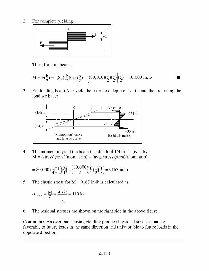
2. For complete yielding,
h/2
F
F0
Thus, for both beams, M = F(h
2) = (Syt)(h2)(b) (h
2) = [ ](80,000)(12)(
12) (
12) = 10,000 in. lb ■
3. For loading beam A to yield the beam to a depth of 1/4 in. and then releasing the
load we have:
0 0
+30 ksi
-25 ksi
+25 ksi-30 ksi80 110
(1/4) in.
(1/4) in.
Residual stresses"Moment on" curve and Elastic curve
4. The moment to yield the beam to a depth of 1/4 in. is given by M = (stress)(area)(mom. arm) + (avg. stress)(area)(mom. arm) = 80,000 1
412
34 + 80,000
214
12
13 = 9167 in•lb
5. The elastic stress for M = 9167 in•lb is calculated as
!elastic = MZ = 9167
112
= 110 ksi
6. The residual stresses are shown on the right side in the above figure. Comment: An overload causing yielding produced residual stresses that are favorable to future loads in the same direction and unfavorable to future loads in the opposite direction.

4-130
SOLUTION (4.90) Known: Two rectangular steel beams having a known tensile yield strength are loaded in bending and Z = I/c is known. The dimensions and a stress concentration factor are given for both beams. Find: (a) For each beam, determine what moment, M, causes (1) initial yielding and (2)
complete yielding. (b) Beam A is loaded to cause yielding to a depth of 6.35 mm. Determine and plot the
distribution of residual stresses that remain after the load is removed. Schematic and Given Data:
A
12.5 mm
25 mm
Z = 1302 mm3
Syt = 550 MPa
25 mmB
Syt
= 2.5Kt
12.5 mm
37.5 mm
12.5 mm
= 550 MPaZ = 1302 mm3
Assumptions: 1. The idealized stress-strain curve is appropriate. 2. The beam is homogenous. 3. There are no residual stresses initially. Analysis: 1. For initial yielding, using Eqs. (4.7) and (4.21), Beam A: ! = Syt = MZ
M = Syt Z = (550 MPa)(1302 mm3) = 716.1 N·m ■
Beam B: ! = Syt = MZ Kt M = SytZKt
= 550 MPa ( )1302 mm3
2.5 = 286.44 N·m ■

4-131
2. For complete yielding,
h/2
F
F0
Thus, for both beams, M = F(h
2) = (Syt)(h2)(b) (h
2) = 550 MPa 252 12.5 25
2 = 1074.22 N·m ■
3. For loading beam A to yield the beam to a depth of 6.35 mm and then releasing
the load we have:
0 0
+208.5 MPa
-176.3 MPa
+176.3 MPa-208.5 MPa550
758.56.35 mm
6.35 mm
Residual stresses"Moment on" curve and Elastic curve
4. The moment to yield the beam to a depth of 6.35 mm is given by M = (stress)(area)(mom. arm) + (avg. stress)(area)(mom. arm)
= 550 MPa6.35 mm 12.5 mm 18.65 mm
+ 550 MPa2 6.15 mm 12.5 mm 8.20 mm
M = 987.54 N·m 5. The elastic stress for M = 987.54 N·m is calculated as
!elastic= MZ =
987.54 N·m1302 mm3 = 758.5 MPa
6. The residual stresses are shown on the right side in the above figure. Comment: An overload causing yielding produced residual stresses that are favorable to future loads in the same direction and unfavorable to future loads in the opposite direction.

4-132
SOLUTION (4.91) Known: A 12 in. length of aluminum tubing with a cross-sectional area of 1.5 in.2 expands 0.008 in. from a stress-free condition at 60°F when the tube is heated to a uniform 260°F. Find: Determine the end loads on the aluminum tubing loads and the resultant compressive stresses. Schematic and Given Data:
12.000 in. 12.008 in.
T = 60 oF T = 260 oF
P = 0 lb P = 0 lb P = ? P = ?
Assumptions: 1. The tube material is homogenous and isotropic. 2. The material stresses remain within the elastic range. 3. No local or column bending occurs. Analysis: 1. For the unrestrained tube
∈ = αΔΤ = ( )12!10-6/"
F ( )200 "F = 2.4x10⁻³ in.in. ΔL = L∈ = 12 in. ( )2.4!10-3 = 0.0288 in.
4-133
2. Since the measured expansion was only 0.008 in., the constraints must apply forces sufficient to produce a deflection of 0.0208 in. From the relationship
! = PL
AE which is from elementary elastic theory, where δ = 0.0208 in., L = 12.000 in.,
A = 1.5 in.2, and E = 10.4 × 10⁶ ksi. With substitution we have
0.0208 in. = P ( )12.000 in.( )1.5 in.2 ( )10.4×10⁶ psi
yielding P = 27,040 lb
3. The resultant stress is, ! = PA =
27,040 lb1.5 in.2
= 18,027 psi ■
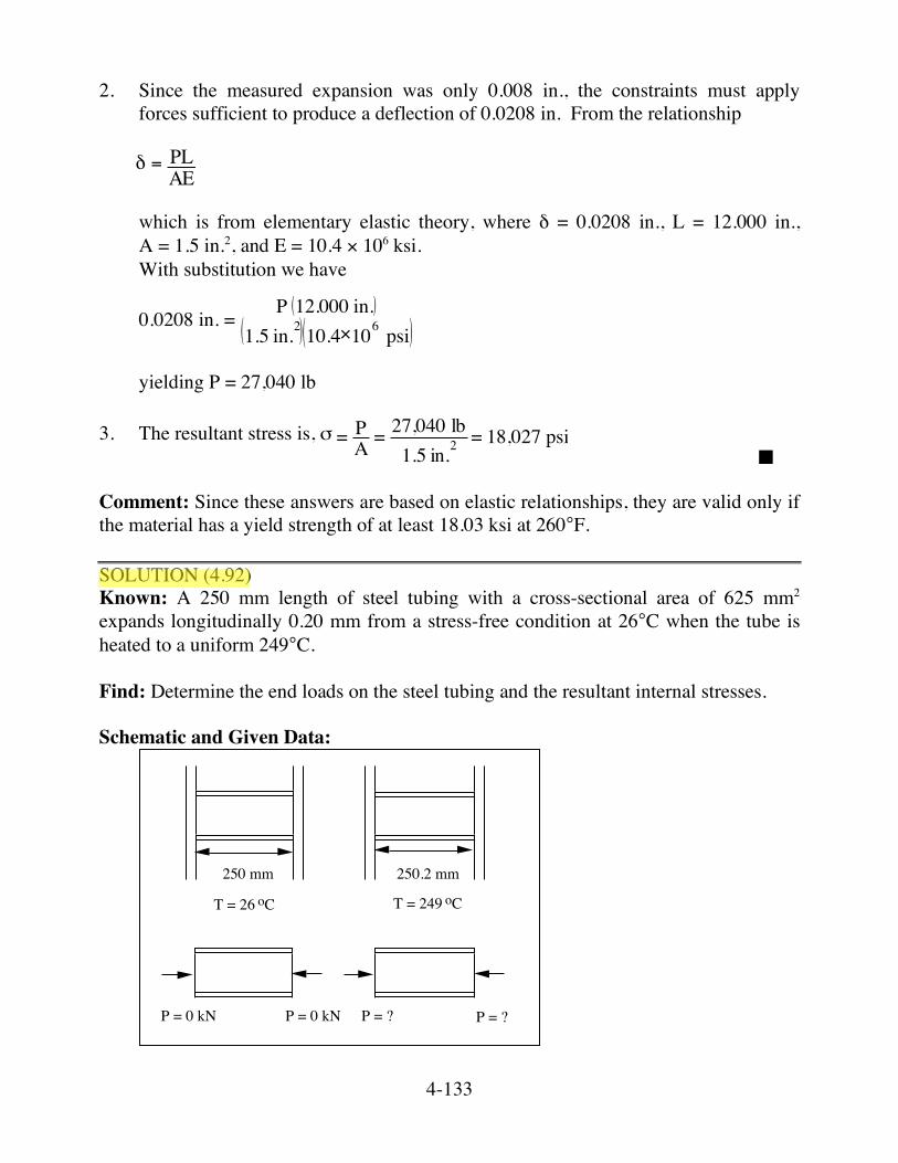
Comment: Since these answers are based on elastic relationships, they are valid only if the material has a yield strength of at least 18.03 ksi at 260°F. SOLUTION (4.92) Known: A 250 mm length of steel tubing with a cross-sectional area of 625 mm2 expands longitudinally 0.20 mm from a stress-free condition at 26°C when the tube is heated to a uniform 249°C. Find: Determine the end loads on the steel tubing and the resultant internal stresses. Schematic and Given Data:
250 mm 250.2 mm
T = 26 oC T = 249 oC
P = 0 kN P = 0 kN P = ? P = ?

4-134
Assumptions: 1. The tube material is homogenous and isotropic. 2. The material stresses remain within the elastic range. Analysis: 1. For the unrestrained tube
∈ = αΔΤ = ( )12!10-6 ( )249-26 = 2.68!10-3 ΔL = L∈ = 250 mm ( )2.68!10-3 = 0.669 mm
2. Since the measured expansion was only 0.20 mm, the constraints must apply
forces sufficient to produce a deflection of 0.469 mm. From the relationship
! = PL
AE which is from elementary elastic theory, where δ = 0.469 mm, L = 250 mm, and
A = 625 mm2 = 625 mm2× 1 m1000 mm
× 1 m1000 mm = 0.000625 m
E = 207!109 Pa = 207!109 Nm2 = 207!10
3 Nmm2
Therefore, 0.469 mm = P 250 mm
625 mm2 207!103 Nmm2
and P = 242,707 N 3. The resultant stress is, σ = 242,707 N
625 mm2 = 388 MPa ■
Comment: Since these answers are based on elastic relationships, they are valid only if the material has a yield strength of at least 388 MPa at 249°C.