rosemount 585 main steam annubar with opposite …/media/resources/... ¢00825-0300-4585[¤ quick...
TRANSCRIPT

www.rosemount.com
¢00825-0300-4585[¤
Quick Installation Guide00825-0300-4585, Rev ABMarch 2012 585 Main Steam Annubar
Step 1: Location and Orientation
Step 2: Drill Mounting Holes into Pipe
Step 3: Weld Mounting Hardware
Step 4: Insert the Annubar
Step 5: Mount the Transmitter
Product Certifications
Start
End
Rosemount 585 Main Steam Annubar® with Opposite Side Support

Quick Installation Guide00825-0300-4585, Rev AB
March 2012585 Main Steam Annubar
© 2012 Rosemount Inc. All rights reserved. All marks property of owner. Rosemount and the Rosemount logotype are registered trademarks of Rosemount Inc.
Rosemount Inc.8200 Market BoulevardChanhassen, MN USA 55317T (US) (800) 999-9307T (Intnl) (952) 906-8888F (952) 906 8889
Emerson Process Management GmbH & Co. OHGArgelsrieder Feld 382234 WesslingGermanyT 49 (8153) 9390F49 (8153) 939172
Emerson Process Management Asia Pacific Private Limited1 Pandan CrescentSingapore 128461T (65) 6777 8211F (65) 6777 0947/65 6777 0743
Beijing Rosemount Far East Instrument Co., LimitedNo. 6 North Street, Hepingli, Dong Cheng DistrictBeijing 100013, ChinaT (86) (10) 6428 2233F (86) (10) 6422 8586
IMPORTANT NOTICE
This installation guide provides basic guidelines for Rosemount585 Annubar. It does not provide instructions for configuration, diagnostics, maintenance, service, troubleshooting, Explosion-proof, Flame-Proof, or intrinsically safe (I.S.) installations. Refer to the 585 Annubar reference manual (document number 00809-0100-4585) for more instruction. This manual is also available electronically on www.rosemount.com.
WARNING
Process leaks may cause harm or result in death. Flowing medium will cause the 585 Annubar assembly to become hot and could result in burns.
WARNING
Emerson Process Management recommends using an experienced pipe fabrication facility to perform the welding of the mounting hardware. This process can be difficult and mistakes could cause failures that result in serious injuries or death.
2

Quick Installation Guide00825-0300-4585, Rev ABMarch 2012 585 Main Steam Annubar
585 Annubar® Assembly Exploded View
NOTEUse an appropriate pipe sealing compound rated for the service temperature on all threaded connections.
Packing Gland Nuts
Packing Gland Washers
Roll Pins
Packing Gland Cover
Packing Gland
Locking Nuts
Locking Washers
Remote Mount Instrument Connections
Locking Rods
585 Sensor
Weldolet
Weldolet
Opposite SideSupport Cap
3

Quick Installation Guide00825-0300-4585, Rev AB
March 2012585 Main Steam Annubar
4
Installation OverviewFor the 585 Main Steam Line Annubar Primary Element, it is critical to install the product correctly and in alignment to prevent failure that could result in serious injury or death. Follow these installation guidelines completely for the best procedure for installation. It is recommended that an experienced pipe fabrication facility be contracted to install the mounting hardware as the alignment and welding are critical to a safe installation. Please contact Emerson Process Management for the list of approved facilities. For best results, please order the alignment bar (Option Code A1) to ensure acceptable alignment of the installation hardware and opposite side support.
STEP 1: LOCATION AND ORIENTATIONCorrect orientation and straight run requirements must be met for accurate and repeatable flow measurements. Refer to Table 1 for minimum pipe diameter distances from upstream disturbances.
Table 1. Straight Run Requirements
Upstream Dimensions
DownstreamDimensions
In Plane
Out of Plane
A A
1
8 10 4
2
11 16 4
3
23 28 4
4
12 12 4

Quick Installation Guide00825-0300-4585, Rev ABMarch 2012 585 Main Steam Annubar
STEP 1 CONTINUED...
NOTE• “In Plane A” means the bar is in the same plane as the elbow. “Out of Plane A” means
the bar is perpendicular to the plane of the elbow.• Row 6 in Table 1 applies to gate throttling valves that are partially opened, as well as
control valves.
Horizontal Orientation
For steam applications, the sensor should be located in the bottom half of the pipe.
Upstream Dimensions
DownstreamDimensions
In Plane
Out of Plane
A A
5
18 18 4
6
30 30 4
Figure 1. Horizontal Orientation
30° Recommended Zone 30°
RecommendedZone 30°
45° 45°
5
Quick Installation Guide00825-0300-4585, Rev AB
March 2012585 Main Steam Annubar
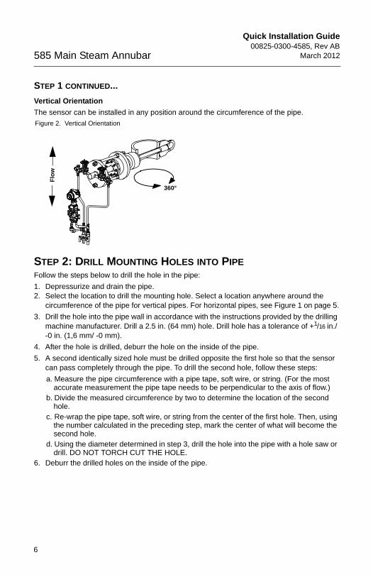
STEP 1 CONTINUED...
Vertical Orientation
The sensor can be installed in any position around the circumference of the pipe.
STEP 2: DRILL MOUNTING HOLES INTO PIPEFollow the steps below to drill the hole in the pipe:
1. Depressurize and drain the pipe.2. Select the location to drill the mounting hole. Select a location anywhere around the
circumference of the pipe for vertical pipes. For horizontal pipes, see Figure 1 on page 5.
3. Drill the hole into the pipe wall in accordance with the instructions provided by the drilling machine manufacturer. Drill a 2.5 in. (64 mm) hole. Drill hole has a tolerance of +1/16 in./ -0 in. (1,6 mm/ -0 mm).
4. After the hole is drilled, deburr the hole on the inside of the pipe.
5. A second identically sized hole must be drilled opposite the first hole so that the sensor can pass completely through the pipe. To drill the second hole, follow these steps:
a. Measure the pipe circumference with a pipe tape, soft wire, or string. (For the most accurate measurement the pipe tape needs to be perpendicular to the axis of flow.)
b. Divide the measured circumference by two to determine the location of the second hole.
c. Re-wrap the pipe tape, soft wire, or string from the center of the first hole. Then, using the number calculated in the preceding step, mark the center of what will become the second hole.
d. Using the diameter determined in step 3, drill the hole into the pipe with a hole saw or drill. DO NOT TORCH CUT THE HOLE.
6. Deburr the drilled holes on the inside of the pipe.
Figure 2. Vertical Orientation
360°
Flo
w
6

Quick Installation Guide00825-0300-4585, Rev ABMarch 2012 585 Main Steam Annubar
7
STEP 3: WELD MOUNTING HARDWARE1. An alignment bar is needed during the welding of the heavy wall weldolets to the steam
pipeline. The alignment bar can be ordered from Emerson Process Management. 2. Weld the heavy wall weldolet to the packing gland assembly with a full
penetration-groove weld.
a. Place the alignment bar through the packing gland and the weldolet. The weldolet will also have a bearing sleeve in it and it should be near the radius end of the weldolet which will be the end welded to the pipe. Ensure the support plate is attached to the packing gland before making the weld.
b. Tack weld the weldolet to the packing gland. Remove the alignment bar.c. Weld the first pass. Recheck alignment with the alignment bar. Adjust alignment as
necessary. Do not allow the alignment bar to get too hot, as it will be difficult to remove. Use it only briefly to check alignment between weld passes.
d. Complete remaining weld passes, using alignment bar to verify alignment several times during the process. Emerson Process Management recommends that the weld thickness is equal to the base metal thickness.
3. Weld the weldolet and packing gland assembly to the pipe.
a. Place alignment bar back into the pipe, slide the weldolet and packing gland assembly down the alignment bar, and let it rest on the pipe.
b. Ensure the 11/8-in. (29 mm) holes in the support plate are perpendicular to the pipe centerline within ± 3° for horizontal lines and parallel to the pipe centerline within ± 3° for vertical lines. This will ensure that the impact and static holes will be in line with the flow stream. See Figure 3 on page 9.
c. Tack weld the weldolet to the pipe. Check alignment. Remove the alignment bar and weld the first pass. Emerson Process Management recommends using TIG welding for the first two passes.
NOTE It is very helpful to have two welders welding the assemblies to pipe, with one welder starting 180° from the other. This helps prevent movement of the fittings during the temperature changes associated with welding.
d. Check the alignment after the first pass. Remove the alignment bar and weld the next pass. Recheck alignment.
e. Continue applying weld passes and rechecking alignment until welding is complete. The fillet welds will be approximately 11/8-in. (29 mm).

Quick Installation Guide00825-0300-4585, Rev AB
March 2012585 Main Steam Annubar
STEP 3 CONTINUED...4. Weld the opposite side weldolet to the pipe.
a. Slide the alignment bar through mounting and hole in top side of pipe and place the opposite-side support weldolet over the end of the alignment bar.
b. Visually center the opposite-side weldolet over the hole. Tack weld the weldolet, using tack bars or an equivalent method.
c. Weld the first pass and check alignment using the alignment bar and continue welding. Check alignment frequently during welding. Adjust weldolet as you are making tacks to keep aligned. Do not leave alignment bar in too long as it will heat up and make it very difficult to remove.
d. When welding is complete, the alignment bar should slide freely through the packing into the opposite-side weldolet.
e. Weld opposite end cap to weldolet using a full penetration groove weld.
5. Perform required heat treatment.
6. Reinstall 585 Main Steam Annubar after heat treating and ensure flow arrow is pointing in the direction of flow.
8

Quick Installation Guide00825-0300-4585, Rev ABMarch 2012 585 Main Steam Annubar
STEP 4: INSERT THE ANNUBAR1. Place the packing into the packing gland with the two split rings (Garlock style 1303FEP)
on the outside and the three Garlock Carbon/Graphite solid die-formed rings on the inside. Make sure the splits in the outer packing are 180° apart.
Figure 3. Packing Gland Assembly
NOTEThe packing gland and support plate will be shipped fully assembled.
2. Slide the 585 Annubar through the packing and install the locking rods, nuts, and lock washers. The dimension between the plates should be 11.0 in. (279 mm). See Figure 4 on page 10. If there is visual access to the inside of the pipe, ensure that the sensing holes are equally spaced from the inner diameter of the pipe.
3. Make the small adjustment (if necessary), then lock the 585 in place with the locking rods, nuts, and lock washers. When installed, the 585 will have a dimension of 29.6 in. (716 mm) from pipe OD to top of head.
4. The last thing to be done is to tighten the packing gland nuts to 25 to 30 ft.-lbs. (34 to 41 Nm). See Figure 5.
Packing Gland Nuts
Packing Gland Washers
Packing Gland Cover
Follower
Packing
Packing Gland Studs
Packing Gland
Support Plate
Support Plate Washers
Support Plate Nuts
Support Plate Studs
9

Quick Installation Guide00825-0300-4585, Rev AB
March 2012585 Main Steam Annubar
STEP 4 CONTINUED...
Figure 4. Install the 585 Sensor
NOTEIf you have visual access of the inside of the pipe, the sensing holes should be equally spaced from each side of the pipe ID.
Figure 5. Tighten the packing gland nuts
Packing gland nuts
10

Quick Installation Guide00825-0300-4585, Rev ABMarch 2012 585 Main Steam Annubar
STEP 5: MOUNT THE TRANSMITTER
Transmitter Mounting with Remote Mount HeadTemperatures in excess of 250 °F (121 °C) at the electronics will damage the transmitter. Remote mounted transmitters are connected to the sensor by means of impulse piping, which allows service flow temperatures to decrease to a point where the transmitter is no longer vulnerable.
Impulse Piping Guidelines:
The following restrictions and recommendations apply to impulse piping location.
1. Impulse piping that runs horizontally must slope downward at least one inch per foot (83 mm/m).
2. Impulse piping should have a minimum length of one foot (0.3048 m) for every 100 °F (38°C) temperature increase over 250 °F (121 °C). Impulse piping must be non-insulated to reduce fluid temperature. Any threaded connections should be checked after the system reaches the intended temperature because connections may come loose with contraction and expansion caused by temperature change.
3. Outdoor installations may require insulation and heat tracing to prevent freezing.
4. When impulse piping is longer than six feet (1.8 m) the high and low impulse lines must be positioned together to maintain equal temperature. They must be supported to prevent sagging and vibration.
5. Impulse lines should be positioned in protected areas or against walls or ceilings. Use appropriate pipe sealing compound rated for the service temperature on all threaded connections. Do not place the impulse piping near high temperature piping or equipment.
General Guidelines:
a. An instrument manifold is recommended for all installations. Manifolds allow an operator to equalize the pressures prior to zeroing and isolates the process fluid from the transmitter.
b. Use only valves and fittings rated for the design pressure and temperature (in some cases the primary instrument valve may be supplied by Emerson Process Management with the Annubar).
c. Use a pipe thread sealant compound that is rated for use at the service temperature and pressure for all valves and fittings.
d. Verify that all connections are tight and that all instrument valves are fully closed.e. Verify that the sensor probe is properly oriented as per the submitted outline drawings.f. The piping used to connect the sensor probe and transmitter must be rated for
continuous operation at the pipeline-designed pressure and temperature. A minimum of one-half inch (1/2-in., 12 mm) O.D. stainless steel tubing with a wall thickness of at least 1/16-in. (1,6 mm) is recommended.
11
Quick Installation Guide00825-0300-4585, Rev AB
March 2012585 Main Steam Annubar
12
STEP 5 CONTINUED...
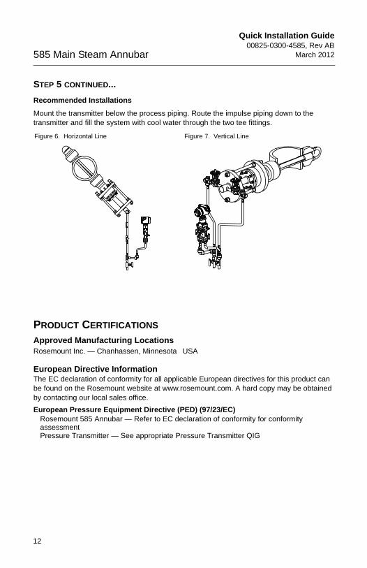
Recommended Installations
Mount the transmitter below the process piping. Route the impulse piping down to the transmitter and fill the system with cool water through the two tee fittings.
PRODUCT CERTIFICATIONS
Approved Manufacturing LocationsRosemount Inc. — Chanhassen, Minnesota USA
European Directive InformationThe EC declaration of conformity for all applicable European directives for this product can be found on the Rosemount website at www.rosemount.com. A hard copy may be obtained by contacting our local sales office.
European Pressure Equipment Directive (PED) (97/23/EC)Rosemount 585 Annubar — Refer to EC declaration of conformity for conformity assessmentPressure Transmitter — See appropriate Pressure Transmitter QIG
Figure 6. Horizontal Line Figure 7. Vertical Line