rollover-vaulting algorithm for simulating vehicle-barrier...
TRANSCRIPT

ROLLOVER-VAULTING ALGORITHM FOR SIMULATING VEHICLE-BARRIER COLLISION BEHAVIOR John J. Labra, James Rudd, and J. Ravenscroft, ENSCO, Inc., Springfield, Virginia
Because of the relatively high center of gravity of most heavy vehicles, the possibility of rollover vaulting is always present when a heavy vehicle collides with a median or bridge barrier. There have been various investigations made on vehicle-barrier response using simulation models that are either too simplified or extremely costly to run. The algorithm developed in this paper incorporates a comprehensive, three-dimensional model of the vehicle-barrier interaction and is very inexpensive to operate. In this algorithm, the vehicle-barrier interaction is assumed to take place in three phases: (a) the initial impulsive impact with the barrier; (b) a continuous, nonimpulsive translational and angular motion during redirection; and (c) a second impulsive impact when the rear of the vehicle swings around and strikes the barrier. The algorithm enables the user to monitor all the important vehicle dynamic parameters, including the angular orientation of the vehicle during redirection and the magnitude of the initial impulsive impact forces between vehicle and barrier. The program is applied to investigate the vaulting potential of passenger and heavy vehicles with various barriers at speeds and impact angles covering the expected range.
•VARIOUS investigations have been made into the behavior of vehicles interacting with median and bridge barriers (!., ; '.!, !, £, ~ 1_). Because of the relatively high center of gravity (e.g.) of most of these heavy vehicles, the possibility of rollover vaulting is always present when such a vehicle collides with a barrier. A relatively simple mathematical procedure for determining the possibility of rollover vaulting has been developed by Dunlap (8). This approach essentially is limited to the case of the vehicle impacting the barrier broadside so that all points along the length of the vehicle impact the barrier simultaneously. In reality, the initial impact of the vehicle is usually restricted to the front corner nearest the barrier. Dunlap (8) extrapolates his method to cover this oblique condition by using certain worst case values for the vehicle's initial kinematic conditions during the interval of redirection. However no general methods for obtaining values of these worst case conditions were presented.
There are two other limitations with the aforementioned procedure (8). First, only rollover potential about the barrier's longitudinal axis is checked. However, the vehicle may be more likely to roll about another axis (lying between the barrier and vehicle axes), and this would not be revealed by Dunlap's analysis. Second, the procedure computes an angular velocity parameter 4ir at each time step during redirection derived from an impulse principle. This assumption is only valid during the initial impulsive contact with the barrier and not during the smooth redirection phase.
In an effort to remove the aforementioned limitations, an improved rollover-vaulting algorithm (RVA) has been developed. In this algorithm, the vehicle-barrier interaction is assumed to take place in three phases: (a) the initial impulsive impact with the barrier at a given angle; (b) a continuous, nonimpulsive translational and rolling motion during redirection; and (c) a second impulsive impact when the rear of the vehicle swings around and impacts the barrier. This third step could conceivably be eliminated by assuming a nonimpulsive motion aJter the initial impact and redirection. However, although this would simplify the procedure, observations of full-scale tests and past simulation results based on the BARRIER VII program (9) reveal that a second impulsive impact situation does indeed occur. Specifically, the RVA program can monitor the following:
1

2
1. The angular orientation of the vehicle during and after the initial impact, 2. The respective angular rates of the vehicle during redirection, 3. The trajectory of the vehicle center of gravity during redirection, 4. The magnitude of the initial impulse between the vehicle and the barrier, and 5. The tire-suspension reaction forces during redirection of the vehicle.
In the algorithm, a vehicle fixed reference frame and an inertial reference frame as shown in Figure 1 are used. The vehicular reference frame origin 0, located at the contact point, is assumed to traverse at a constant speed in the plane of the barrier. After the initial impact at 0, the vehicle is assumed to rotate about this moving impact point during the redirection phase.
To maintain low computer costs when implementing the RVA program, certain simplifying assumptions have been made. These include
1. A six degree of freedom, rigid body representation for the vehicle without sepa-rate degrees of freedom for the wheels;
2. A single impact point moving with a constant velocity during redirection; 3. A representation of a linear spring and dashpot tire-suspension force; and 4. An undeformable vehicle-barrier interface.
As a result, the computer run time for evaluating a typical impact is extremely short (approximately 2 sec of CP time on a CDC 6000 Series machine). Thus, reliable rollover-vaulting information can be obtained at a fraction of the cost required for other existing three-dimensional vehicle-barrier simulations.
With the RVA program, vaulting potential for any single-unit vehicle may be investigated by inserting the relevant weight and geometric parameters. The program was used to investigate impacts of a 45,500-lb (20 638-kg) truck, a 40,000-lb (18 144-kg) bus, and a 4,000-lb (1814-kg) car with a rigid barrier of variable height for various impact conditions. For the truck, the results indicated no vaulting for tbe 10 and 15-deg impact angles for barrier heights ~ 30 in. (76.2 cm) . However, rollover vaulting was predicted for the 25-deg impact. For the car, the results indicated no vaulting for any of the runs. This is attributed to the relatively low center of gravity position with respect to the barrier's longitudina l roll axis. In the case of the bus simulations, vaulting was predicted with the 27-in. (68.6-cm) barrier at 60 mph (96.5 km/h) and the 25-deg impact angle. However, for the 39-in. (99.1-cm) barrier, no vaulting occurred during the run at 60 mph (96. G km/h) and 2 5 deg. Further applications of the RV A program to investigate rollover vaulting in the case of flexible barriers are discussed later.
INITIAL IMPACT
In the RVA program when the vehicle first impacts the barrier, an impulsive situation is assumed to exist. Based on the angular momentum principle about the vehicle's e.g., the angular velocity components w1, w2, and W3 about their respective vehicle fixed axes x, y, and z, assumed to be zero before impact, are defined by the following:
Wl
II 4{ II W?. = i'" x p
lw3 I
where
II ff.f II = the vehicle's moment of inertia matrix about its e.g.,
(1)

I I
Figure 1. Vehicle impacting barrier. Y'
Ine rtia1~<-----~
Reference Frame
Figure 2. Side and bottom views of vehicle.
Table 1. Vehicle parameters.
Parameters Car Bus
M, lb 4,000 40,000 X1, in.
39-in. barrier -91 -2-70 27-in. barrier -91 -270
y1, In . 39-in. barrier -37 -48 27-in. barrier -37 -48
z1, in . 39-ln. barrier 15 -16 27- in . barrier 3 -28
l~j '' , lbf-sec2 - in. I,. 4,500 211,000 I,, 25,000 2, 509,000 I,. 39,000 2, 500,000 I,, 0 0
y
Truck
45, 500
-172 -172
-38 -38
-16 -28
126, 536 385, 543 487,358 0
Note: 1 lb= 0.45 kg , 1 In. = 2.54 cm. 1 lbf·sec 2-ln. = 11 .29 N·s'-cm.
Vehi c l e
"----.----
Parameters
a, in. b, in . c,, in. Cit, in . d, in. a11, and O:Lr, lbf-sec/in. ~1111 and Cl!L11, lbf- s ec /in. /3" and /3", lbf /3 .. and /3..,., lbf E"Lr and e:Rr, in. / sec E"L11 and E".1111, in./sec [{,,, and kc., lbf/in. k111t and kL1t, lbf/ln.
1Vch icle flxcd Refer ence Frame
--+---X
~ y
Car Bus Truck
59 240 136 57 101 42 30 36 40 30 36 36 24 55 55 3.5 4.16 4.16 3.9 4.16 0 55 2,200 1, 100 50 2,200 2,200 0.001 0.001 0.001 0.001 0.001 0.001 131 4, 700 2,300 192 4, 700 4, 700
1 lbf·sec/in. = 1.75 N-s/cm. 1 lbf = 4.45 N, 1 lbf/ln. = 175.1 N/m.

4
r = the moment arm from the vehicle's e.g. to the impact point 0 on the barrier, and
P = the impulsive force between vehicle and barrier.
Based on the linear momentum principle during this initial impact phase, we also obtain
M (v: - Vx) -:P.
M v; -:Py (2)
Mv: -:Pz
where
v., o, 0 the initial translational velocity of the e.g. before impact in the vehicle fixed longitudinal direction;
v;, v;, v:
M
the e.g. velocity components immediately after impact, with respect to the vehicle fixed coordinate system; the impulsive force components in the negative vehicle fixed x, y, z directions; and the mass of the vehicle.
Assuming that the component of the impulsive force in the plane of the barrier can be ignored, we have
P. cos I/lo - Py sin l/!o
:P, ~ } (3)
where l{J 0 is the initial yaw angle between the vehicle and the barrier. In addition, the relationship between the vehicle e.g. velocity and the contact point
velocity is
v: v' = y
v' z
where
Vpx w 2Z1 - W3Y1
Vpy + W3X1 - W1Z1
Vpz W1Y1 - W2X1
the components of the contact point 0 velocity in the vehicle fixed system, and the components of the vector from point 0 to the e.g .
(4)
.t<·urthermore, the componenii; Y-P., ·v· PY• auu ·v·pz u.L i.l1t: l:uui.i:il:i pviul: ·vt:lucil:y iii tl1~ iil~:i-tial reference frame may be written as
(5)

where
// All=
cose cos~
cosa siniJ>
-sine
: -cosiJi sinip + s in¢ s ine cos l/J
! cos¢ cos ip + sin¢ sina s in¢ I I I cosa s in¢
l sin¢ sin¢ + cos¢ sine cosl/J I I : -cosip sin¢ + cos¢ sine sinip I I I cose cos¢
which is the transformation matrix from the vehicle fixed to the inertial reference frame, and
e, ¢, l/J = the pitch, roll, and yaw angles for the vehicle.
Finally, if we now assume the vehicle remains in contact with the barrier at point 0 during redirection, we also have the following additional constraint:
0
5
(6)
Coupling this constraint with equations 1, 2, 3, 4 and 5 yields the resulting angular and translational velocities of the vehicle after the initial impact. These velocities then define the initial conditions for the second phase of the impact discussed in the next section.
MOTION DURING REDIRECTION
After the initial impact with the barrier, the vehicle is assumed to remain in contact with the barrier at point 0. In addition, the contact point is assumed to traverse at a constant velocity. Through this assumption, the rotational equations of motion about the point 0 have the form of the Euler equations of motion:
where
WI
II I';J II · W2 = IE I + :EM o (7)
W3
= the vehicle's moment of inertia matrix about the vehicle-barrier contact point O,
= the resulting moments about point 0 due to the tire-suspension reaction forces (Appendix),
(8)
are the nonlinear inertial terms in the equations of motion, where

6
A1 = y1 cose cos¢ -z1 sin¢ cose,
A2 = x1 cose cos¢ +z1 sine, and
A3 = x1 sin¢ cose + y1 sine.
The initial value of angles 0, ¢, and ip in equation 8 are taken to be those defined for the vehicle before impact (e.g., a = ¢ = O; ip = I/Jo). The initial angular velocities w1, w2, and W3, on the other hand, are those values obtained from equation 1. In addition, during the period of redirection, the forces assumed to act about the contact point are the tire suspension reaction forces (Appendix) and the vehicle's weight . To solve equation 7 for each time increment At, values of angles e, ¢, and ip for time t are required. These are obtained from the following:
e
le [w2 sin¢ + W3 COS¢] \ cos
w1 + w2 sin¢ tane + W3 cos¢ tane
w2 cos¢ - W3 sin¢
(9)
By integratingthe solutions to equations 7 and 9 and by using in both equations the previous values for w1, w2, W3 and e, ¢, ip, one obtains the vehicle angular velocity and corresponding angle orientations for any time t.
When the vehicle has been redirected to a position where the yaw angle ip is zero, the second impulsive impact is assumed to occur.
SECONDARY IMPACT
From observations of full-scale tests and simulation results, it became apparent that, after the impacting vehicle redirects parallel to the barrier, a second impulsive situation exists. This was noted especially for the longer and heavier vehicles such as trucks and buses.
For simulation of this second impulsive impact, the vehicle's orientation is monitored during redirection until the yaw angle ip between vehicle and barrier is zero. At this point, the second impact is assumed to take place. Impulse principles are again used to determine the resulting motion. Here it is assumed that after impact the resulting angular motion is purely about the barrier longitudinal axis X. Based on this assumption, the equation of motion is
u
11I;J11 o
0
I wi I
• W3
(10)

where
II 1;J II = the inertia matrix of the vehicle about the contact point 0 with respect to the inertial XYZ coordinate system,
7
w1, w2, w; = the vehicle angular velocity components immediately before impact with respect to the inertial reference frame,
~. O, 0 = the resulting vehicle angular velocity vector immediately after impact about the inertial X axis, and
O, T2, T3 = the impulsive torque components.
To determine if the resulting angular velocity ~about the barrier 's longitudinal axis is sufficient to cause rollover vaulting of the vehicle, the critical angular velocity ~Rv for vaulting is first evaluated. This is found by using the conservation of energy principle after the sec.ond impulsive impact:
(11)
where
KE = kinetic energy, PE = potential energy, and i, f = subscripts indicating initial and final respectively.
The initial potential energy after secondary impact is
(12)
where
W v = the weight of the vehicle, and D = the vertical height of the e.g. with respect to the inertial reference frame, at
the instant of secondary impact.
The initial kinetic energy after impact is simply
1 * ~ KE 1 = /:i I, w (13)
where r; is the vehicle's moment of inertia about the barrier's longitudinal axis (inertial X axis).
The limiting case of rollover vaulting occurs when KE, is zero at the instant the vehicle e.g. is vertically above the barrier. In this case,
t%> + (3 = 90 deg (14)
where
8 = tan-1 [ (-z1 coseo)/y1], and (15) e0 = pitch orientation of the vehicle at the instant of secondary impact.
Determination of the vertical height of the e.g. in this configuration is obtained by substituting «-from equation 14 into the third row of the transformation matrix II A II, that is,

8
(16)
The potential energy at this instance is then
(17)
Substituting equations 12, 13, and 17 into equation 11, we obtain, for the critical angular velocity,
ci>R V (18)
Thus, if the roll rate ~ obtained from equation 10 is equal to or greater than ~v, i.e.,
then rollover vaulting will take place.
IMPLEMENTATION OF RVA PROGRAM AND SIMULATION RESULTS
(19)
The foregoing theoretical developments were amalgamated into an algorithm and coded for placement on a CDC 6400 system. Using the RVA program, simulations were made for a car, an inner-city truck, and a bus impacting a rigid barrier. The vehicular speeds and impact angles initially considered were (1 mph = 1.6 km/h):
1. 60 mph/7 deg, 2. 60 mph/ 15 deg, and 3. 60 mph/ 25 deg.
Corresponding to these impact conditions, two configurations of barriers were initially considered, consisting of a 27-in. (68.6-cm) concrete parapet with and without a 12-in.-high (30 .5-cm) steel railing [heights of 39 in. (99.1 cm) and 27 in. (68.6 cm) respectively]. The vehicle geometric parameters, as shown in Figures 1 and 2, and tiresuspension force parameters (as defined in the Appendix) are given in· Table 1.
With the vehicle parameters given in Table 1 for a car, bus, and inner-city truck, a series of simulations were made by using the RVA program. The results for the various impacts are given in Table 2 and are shown in Figure 3.
"Fr.nm thP. :ihove defined simulations, all runs at the 7 and 10-deg impact angles resulted in satisfactory nonvaulting vehicle behavior. In addition, the It> anct ~5-ciegangle impacts for the automobile also resulted in satisfactory behavior modes. However, the bus vaulted the 27-in. (68.6-cm) barrier at 60 mph (96.5 km/ h) and 25 deg, and the truck vaulted the 27-in. (68.6-cm) barrier at 60 mph (96 .5 km/ h) and 15 deg.
Since there is no energy dissipation through vehicle sheet metal or barrier deformation in the RVA program, the ratio value (Table 2) of 1.0 should be COl')Sidered only as an estimate of vehicle vaulting potential. This is further emphasized when one considers that, under full-scale test conditions, when a vehicle impacts a contoured rigid

I·
Table 2. Potential of vehicles to vault barriers at various speeds and impact angles.
Barrier 60 mph and 7 Deg 60 mph and 10 Deg 60 mph and 15 Deg 60 mph and 25 Deg Height
Item (in.) Position Ratio .. Position Ratio' Position Ratio a Position
Car 39 Stable -0.42 Stable -1.39 Stable 27 Stable -0.07 Stable -0.22 Stable
Bus 39 Stable 0.18 Stable 0.08 Stable 27 Stable 0.20 Stable 0.52 Vault
Truck 27 Stable 0.52 Vault 1.11 30 Stable 0.41 Stable 0.93 Vault 31 Stable 0.38 Stable 0.87 Vault 32 Stable 0.34 Stable 0.81 Vault 33 Stable 0.31 Stable 0.75 Vault 35 Stable 0.25 Stable 0 63 Vault 37 Stable 0.23 Stable 0.52 Vault 39 Stable 0.21 Stable 0.41 Vault 41 Stable 0. 19 Stable 0.30 Vault
Note: 1 mph = 1 61 km/h. 1 in. =" 2.54 cm_
a,j,N1Av· If greater than unity, the truck vaults when impacting a noncontoured parapet or a fl ex ible barrier
Figure 3. Rollover-vaulting potential for 45,500-lb (20 638-kg) inner-city truck.
> ~ ,.,
' ... 0 ·~ .., " "'
3.0
2. 8
2. 6
2 .4
2. 2
2. 0
1. 8
1. 6
l. 4
1. 2
l. 0
0. 8
0.6
0.4
0 .2
30"
Table 3. Vehicle orientation at secondary impact.
60 mph/25°
Crit i cal Value
32" 34 11 36 11 38 11
Barrier Height (In.)
Ratio"
-3 .89 -0 .51
0.52 1.58
3.02 2.77 2.55 2.33 1.95 1.61 1.31 1.03
40"
60 mph and 7 Deg 60 mph and 15 Deg 60 mph and 25 Deg Barrie r He ight ¢ ~ 4> ¢ a 4> ¢ e
Item (in.) (deg) (deg) (deg/ sec) (deg) (deg) (deg/sec) (deg) (deg)
Car 39 -0.3 0.1 -67. 6 -15.5 0 -188.3 -27 .8 3.6 27 -1.4 0 -15.2 -3. l 0.3 -46.4 -5.3 0.9
Bus 39 -0.6 0 24.5 0.4 0.3 11.3 11. 5 1.2 27 -1.4 0.1 24.2 9.4 0.9 64.0 28.0 1.9
Truck 39 -0.6 0.1 31.0 2.2 0.3 61.4 8. 5 0.4 27 2.2 0.2 61. 7 7.2 0.6 130.5
Note: 1 mph= 1,6 km/h 1 in. = 2.54 cm.
42"
4> (deg/sec)
- 384.7 -105.3
76.2 195.4
183.0
10
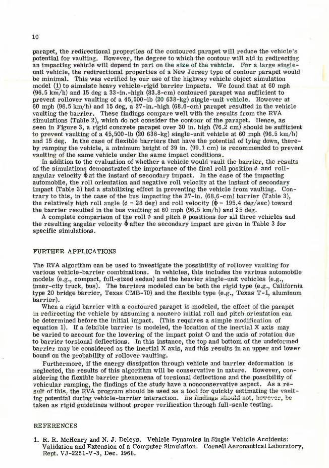
parapet, the redirecttonal properties of the contow·ed parapet will r educe the vehicle 's potential for vaulting. However, the degree to which the contour will aid in redirecting an impacting vehicle will depend in part on the size of the vehicle. For a large s ingleunit vehicle, the redirectional properties of a New Jersey type of contour parapet would be minimal. This was verified by our use of the highway vehicle object simulation model (1) to simulate heavy vehicle-rigid barrie1· impacts. We found that at 60 mph (96.5 krll/ h) and 15 deg a 33-in.-high (83.8-cm) contoured parapet was sufficient to prevent rollover vaulting of a 45,500-lb (20 638-kg) single-Wlit vehicle. However at 60 mph (96.5 km/ h) and 15 deg, a 27-in.-high (68.6-cd:i) parapet resulted in the vehicle vaulting the barrier. These findings compare well with the results from the RVA simulations (Table 2), which do not consider the contour of the parapet. Hence, as seen in Figure 3, a ri.gid concrete parapet over 30 in. high (76.2 cm) should be sufficient to prevent vaulting of a 45,500-lb (20 638-kg) single-unit vehicle at 60 mph (96.5 km/ h) and 15 deg. In the case of flexible barriers that have the potential of lying down, thereby ramping the vehicle, a minimum height of 39 in. (99.1 cm) is recommended to prevent vaulting of the same vehicle under the same impact conditions.
In addition to the evaluation of whether a vehicle would vault the bar rier , the results of the simulations demonstrated the importance of the final roll position 0 and rollangular velocity ~at the instant of secondary impact. In the case of the impacting automobile, the roll orientation and negative roll velocity at the instant of secondary impact (Table 3) had a stabilizing effect in preventing the vehicle from vaulting. Contl'ary to this, in the case of the bus impacting the 27-in. (68.6-cm) barrier (Table 3), the relatively high roll angle (</J = 28 deg) and roll velocity (~ = 195.4 deg/sec) toward the barrier resulted in the bus v.aulting at 60 mph (96.5 km/ h) and 25 deg.
A complete comparison of tp.e roll r/I and pitch e positions for all three vehicles and the resulting angular velocity ~after the secondary impact are given in Table 3 for specific simulations .
FURTHER APPLICATIONS
The RVA algorithm can be used to investigate the possibility of rollover vaulting for various vehicle-barrier combinations. In vehicles, this includes the various automobile models (e .. g., compact, full-sized sedan) and the heavier single-unit vehicles (e.g., inner-city truck, bus). The barriers modeled can be both the rigid type (e.g., California type 20 bridge barrier, Texas CMB-70} and the flexible type (e.g., Texas T-1, aluminum barrier).
When a rigid barrier with a contoured parapet is modeled, the effect of the parapet in redirecting the vehicle by assuming a nonzero initial roll and pitch orientation can be determined before the initial impact. {This requires a simple modification of equation 1). If a felxible barrier is modeled, the location of the inertial X axis may be varied to account for the lowering of the impact point 0 and the axis of rotation due to barrier torsional deflections. In this instance, the top and bottom of the undeformed barrier may be considered as the inertial X axis, and this results in an upper and lower bound on the probability of rollover vaulting.
Furthermore, if the energy dissipation through vehicle and barrier deformation is neglected, the results of this algorithm will be conservative in nature. However, considering the flexible barrier phenomena of torsional deflections and the possibility of vehicular ramping, the findings of the study have a nonconservative aspect. As a re!'•.1lt nf this , the RVA program should be used as a tool for quickly estimating the v:.lnlt ing potential dw·ing vehicle-barrier interaction. its iim.iii.1~~ .;h&u.ld ;.ct, hc':.· e~·e1·, be taken as rigid guidelines without proper verification through full-scale testing~
REFERENCES
1. R.R. McHenry and N. J. Deleys. Vehicle Dynamics in Single Vehicle Accidents: Validation and Extension of a Computer Simulation. Cornell Aeronautical Laboratory, Rept. VJ-2251-V-3, Dec. 1968.

, .
11
2. T. J. Hirsch, G. G. Hayes, and E. R. Post. Vehicle Crash Test and Evaluation of Median Barriers for Texas Highways. Texas Transportation Institute, Texas A&M Univ., Research Rept . 146-4, June 1972.
3. R. D. Young, H. E. Ross, Jr., and R. M. Holcomb. Simulation of Vehicle Impact With the Texas Concrete Median Barrier. Texas Transportation Institute, Texas A&M Univ., Research Rept. 140-5, Vol. 1, June 1972.
4. T. J. Hirsch and E. R. Post. Truck Tests on Texas Concrete Median Barrier. Texas Transportation Institute, Texas A&M Univ., Research Rept. 146-7, Aug. 1972.
5. M. P. Jurkat and J. A. Starrett. Automobile-Barrier Impact Studies Using Scale Model Vehicles. Highway Research Record 174, 1967, pp. 30-41.
6. E. F. Nordlin, R. N. Field, and R. P. Hackett. Dynamic Full-Scale Impact Test of Bridge Barrier Rails. Highway Research Record 83, 1965, pp. 132-168.
7. E. F. Nordlin and R. H. Field. Dynamic Tests of Steel Box Beam and Concrete Median Barriers. Highway Research Record 222, 1968, pp. 53-88.
8. b. F. Dunlap. Curb-Guardrail Vaulting Evaluation. Highway Research Record 460, 1973, pp. 10-19.
9. G. H. Powell. Computer Evaluation of Automobile Barrier Systems. Univ. of California, Berkeley, Rept. UC SESM 70-17, Aug. 1970.
· APPENDIX
TIRE-SUSPENSION REACTION FORCES
During the interval of vehicle redirection after the initial impact with the barrier, the roll and pitch orientations are determined by the vehicle dynamic system. These changes result from the vehicle's initial velocity conditions, weight, and the tiresuspension system's reaction forces during redirection.
The tire-suspension forces are assumed to amount to linear springs with viscous and coulomb damping, that is,
(20)
where
LJ = the subscripts for right front (RF), left front (LF), right rear (RR), and left rear (LR) tire locations on the vehicles,
k 1J = the equivalent tire-suspension system spring stiffnesses for each wheel, ~tJ_ = the viscous damping coefficients for the individual wheels, /3 1J = the coulomb damping coefficients for the individual wheels, ? tJ = the individual vertical tire displacements in the inertial coordinate system, and Z {J = the individual vertical tire velocities in the inertial coordinate system.
Although the k u and a ,J are constant, the /3 u terms are defiried as
I 0 for I Z { J I s ~ 1 J
{3,J sgn (Z{J) for I Z(J I> ~IJ (21)

12
where
/j , J the constant damping coefficients, and € 1 J = t he friction-lag coefficie11ts for t he front and rear suspensions.
These tire-suspension reaction forces are assumed, for s implicity, to be in the negative inertial Z direction. Hence, equation 20 may be transfor med to the vehicle fixed reference frame by using the transformatio11 matrix, that is,
F,JX 0
0 (22)
These reaction forces result in restoring moments about the impact point 0 as the vehicle redirects. These moments are included in the equations of motion and are, as previously defined in equation 7,
r;M¢ = (FRrv + FLFv + FRRv + FLRv) (z1 + d)
+ FRRZ(y1 +CR)+ FRn(Y1 +Cr)
r;M~ = -Fl.n(y1 - Cr) - FLRx(Y1 - CR)
- F RRX (y1 + CR) - F RFX (Y1 +CF)
where a, b, CF, CR, and dare vehicle parameters as shown in Figure 2.
(23)
(24)
(25)