rodsteward: a design-to-assembly system for fabrication
TRANSCRIPT
Pacific Graphics 2019C. Theobalt, J. Lee, and G. Wetzstein(Guest Editors)
Volume 38 (2019), Number 7
RodSteward: A Design-to-Assembly System for Fabrication using3D-Printed Joints and Precision-Cut Rods
Alec Jacobson, University of Toronto
Fabrication-aware design Guided assembly3D-printed joints
Laser cut rods
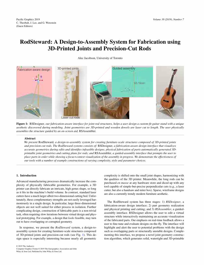
Figure 1: RSDesigner, our fabrication-aware interface for joint-rod structures, helps a user design a custom-fit guitar stand with a uniqueaesthetic discovered during modeling. Joint geometries are 3D-printed and wooden dowels are laser cut to length. The user physicallyassembles the structure guided by an on-screen aid, RSAssembler.
AbstractWe present RodSteward, a design-to-assembly system for creating furniture-scale structures composed of 3D-printed jointsand precision-cut rods. The RodSteward systems consists of: RSDesigner, a fabrication-aware design interface that visualizesaccurate geometries during edits and identifies infeasible designs; physical fabrication of parts automatically generated 3D-printable joint geometries and cutting plans for rods; and RSAssembler, a guided-assembly interface that prompts the user toplace parts in order while showing a focus+context visualization of the assembly in progress. We demonstrate the effectiveness ofour tools with a number of example constructions of varying complexity, style and parameter choices.
1. Introduction
Advanced manufacturing processes dramatically increase the com-plexity of physically fabricable geometries. For example, a 3Dprinter can directly fabricate an intricate, high genus shape, so longas it fits in the machine’s build volume. In contrast, standard lasercutters have a much larger albeit two-dimensional cutting bed. Unfor-tunately, these complementary strengths are not easily leveraged har-moniously in a single design. In particular, large three-dimensionalobjects are not well suited for either process in isolation. Furthercomplicating design, construction of fabricable parts is a non-trivialtask, often requiring slow iterations between virtual design and phys-ical prototyping. For example, a design that looks feasible, may turnout to have overlapping or corrupted geometry.
In response, we present the RodSteward system, a design-to-assembly system for creating furniture-scale structures composedof 3D-printed joints and precision-cut rods (see Fig. 1). This de-sign space is especially interesting because nearly all geometric
complexity is shifted onto the small joint shapes, harmonizing withthe qualities of the 3D printer. Meanwhile, the long rods can bepurchased en masse at any hardware store and diced up with anytool capable of simple-but-precise perpendicular cuts (e.g., a lasercutter, but also a handsaw and miter box). Sparse, wireframe designsare also a currently trendy modern furniture aesthetic.
The RodSteward system has three stages: 1) RSDesigner, afabrication-aware design interface; 2) part geometry realizationand physical printing and cutting; and 3) RSAssembler, a guided-assembly interface. RSDesigner allows the user to edit a virtualstructure while interactively maintaining an accurate visualizationof the fabricated parts. Our emphasis on real-time feedback allows auser to fine-tune and evaluate designs on-the-fly. The interface willhighlight and alert the user to potential problems with the designsuch as overlapping parts or structurally unstable designs. Comple-menting this interface, we propose a novel joint geometry construc-tion algorithm, which generates solid, watertight and 3D-printable
© 2019 The Author(s)Computer Graphics Forum © 2019 The Eurographics Association and JohnWiley & Sons Ltd. Published by John Wiley & Sons Ltd.

Alec Jacobson, University of Toronto / RodSteward: A Design-to-Assembly System for Fabrication using 3D-Printed Joints and Precision-Cut Rods
bin-packed cuts
Figure 2: We pack all of the rod-lengths into a single cut plan overa small number of raw rods. Rods are positioned in place using a
“comb” jig with holes cut at regular intervals matching the spacingof the automatically generated cut plan.
joints given the user’s rod-joint network description. A subset ofexisting methods require manual intervention to generate the literalgeometry of each joint, breaking the exploratory design loop. Incontrast, our method belongs to the class of automatic methods witha tight design loop that allows the user to focus on the high-level cre-ative aspects of the overall design, rather than the geometry of eachjoint itself. With varying physical accuracy, some previous methodshave simulated the structural stability of rod-joint structures. Ourcontributions complement this particular well-explored feature, andwe therefore leave incorporating this aspect as an incremental im-provement to RodSteward. Instead, we focus on first-order designissues such as rod-intersections and balance.
Upon design completion, we automatically engrave each jointwith a visible I.D. and send the parts to the 3D-printer. For rods,we generate a cutting plan that packs the segments into a minimalnumber of standard-size rods, so all can be cut in a single, quickjob (see Fig. 2). After fabricating the individual parts, RSAssemblervisualizes the partial structure as the user places each part. The userpresses a hotkey to advance and the guide suggests the next part toplace and updates the visualization. Without the guided assemblyinterface, assembling these complex structures would reduce tosolving a frustratingly difficult 3D puzzle.
We demonstrate the effectiveness of RodSteward as a design-to-assembly system, by constructing structures (e.g., Fig. 3) thathighlight the simplicity and generality of our system to accom-modate non-manifold edge-networks, circular and polygonal rodprofiles, acute angles between adjacent rods, and complex yet non-self-intersecting and balancing structures.
2. Related Work
In the past decades, designers, researchers and hobbyists alike havelooked for ways to leverage the geometric complexity afforded by3D printing with traditional or unconventional parts. We focus thediscussion of previous works on those similar in terms of interfaceaspirations or methodologies. The main differences with our workare: our end-to-end, design-to-assembly system; the fabrication-aware tight interactive design loop, and interactive guided assemblyplan. To our knowledge, no such complete system exists.
2.1. Design and assembly
The human-computer interaction and graphics communities haveembraced computational fabrication and its evolution beyond classic
computed-aided design and manufacturing (see, e.g., [MBM∗15,UBM15, BKLZ17, LEM∗17]). We join this field of research inrejecting the idea that the existence of mass-production should pre-clude an individual’s opportunity to participate in the unique designand customization of everyday objects (e.g., see Fig. 1).
We are especially interested in hybrid or heterogeneous sys-tems that combine 3D-printing with other materials to create largerobjects. For example, Kovacs et al. [KSW∗17] build room- andarchitectural-scale objects with 3D-printed joints and recycled PETbottles. While their 3D-printed geometry construction is also au-tomatic, their trusses result from intersecting a 3D shape with atetrahedral honeycomb, so joints are less general with fixed topology.Kovacs et al. [KIL∗18] incorporate actuation to create articulatedstructures, but the fixed joint configuration remains. In contrast toour design-to-assembly system, the interface contributions of thesemethods stop at fabrication: the user is left to build a complex struc-ture with many labeled parts and no explicit instructions. Unlikethis and other tools that only focus on design and fabrication, weconsider the end-to-end system from design to assembly.
Leen et al. [LRL17] introduce a tangible, modular magnet-basedinterface for designing wireframe objects. This work complementsours and could provide input to our RSDesigner tool, although theirsensor rods have upper and lower bounds on length and joints canonly accommodated a fixed number of incident rods at boundedangles. Meanwhile, Agrawal et al. [AUK∗15] physically sketch verygeneral, yet temporary 3D wireframe structures made of tape.
Mueller et al. [MIG∗14] break away from layer-by-layer 3Dprinting to fabricate wireframe structures by extruding plastic in3D. Wu et al. [WPGM16] and Huang et al. [HZH∗16] extend thisidea to a larger class of wireframe surfaces using a 5DOF printer,while Huang et al. [HGM18] plan paths for wireframe prints. Penget al. consider the design of such wire-print objects via a traditionalvirtual surface modeling tool [PWMG16] and later an augmentedreality 3D drawing interface [PBW∗18]. These methods focus onwireframe surfaces and the design constraints are largely governedby printhead clearance during toolpathing and structural concerns.No assembly is necessary, but structures are smaller and denser.
Recently, Chidambaram et al. [CZS∗19] introduce a design toolfor wireframe objects constructed via 3D-printed connectors andmetal wires. While their tool provides design suggestions, theirmethod does not detect infeasible designs due to overlapping rodsand does not alert the user if their design will balance. Their toolcomputes a stress visualization, but neither complete descriptionof the method nor accuracy validations are provided. In this designspace, the (strong) wood undergoes bending and stress concentratesat the (significantly weaker) plastic joints. It is unclear whetherthe space frames of Chidambaram et al. are the appropriate model.Their method is also restricted both by a hard bound on the lengthof wires (3cm) and the angle between rods (35°) in order to safelyconstruct 3D-printed connectors by unioning sphere and cylindergeometries. Due to this strict minimum angle constraint, it would beimpossible for their system to accommodate the designs in Figures1 (16°), 3 (26°), 12 (22°), or 14 (30°). Instead, we propose a moregeneral joint construction algorithm that accommodates arbitraryangles, sizes, thicknesses, tolerances and polygonal rod profiles. Asa result, our design space is larger and less constraining to the user.
© 2019 The Author(s)Computer Graphics Forum © 2019 The Eurographics Association and John Wiley & Sons Ltd.

Alec Jacobson, University of Toronto / RodSteward: A Design-to-Assembly System for Fabrication using 3D-Printed Joints and Precision-Cut Rods
Visualization during design Assembled structure
Figure 3: RSDesigner displays a visualization closely matching theeventual fabrication, reducing surprise at assembly time.
Chidambaram et al. provide assembly guidance, but only in the formof connector/wire indices and a printed lookup table of rod lengths.Our RSAssembler interface suggests an assembly ordering guidedby a focus+context visualization.
Dritsas et al. [DCS17] create a sequence of GRASSHOPPER scriptsto aid in the design of structures similar to our results. Given adesired rod diameter, they determine minimum angle of incidentjoints allowed by their scripts and prevent/reject designs that do notmeet this criteria. The generated joints are not guaranteed to be solidmodels which may cause printer failures. The interactive design orassisted assembly problems are not considered, so the user must(presumably) assemble a collection of similar looking parts.
Magrisso et al. [MMZ18] propose a user-assisted process to gen-erate 3D-printable carpentry joinery. Their goal is different fromours. They seek to enhance traditional manual carpentry with ad-vanced manufacturing of individual joints, without placing a strongemphasis on real-time feedback of a tight design loop for the overallobject. This process creates intricate joineries. The design remainscreative, but also relies on the user for non-creative tasks such assupervision of the heuristic when it fails and tuning parameters torecover a feasible design. Our, in comparison, modest joint genera-tion is fully automatic. This allows the user to focus on the creativetask of designing the overall object, facilitated by immediate feed-back and accurate visualization. The user never concerned with theprecise meshing or representation of the joint geometry, only thehigh-level design of the structure. Tian et al. [TSC∗18] create alibrary of CNC-millable joineries to create a woodworking inter-face. These beautiful results utilize a different and complementaryfabrication process and design space.
We are inspired by the early interactive exploration work ofUmetani et al. [UIM12]. Our contributions are complementary: theirmethod considers loads on panel-based furniture, but does not con-sider intersections that would prevent construction during designexploration. Later, Garg et al. [GJG16] visualize collisions duringchoreography and arrangement of space-time reconfigurables, butdo not consider geometric modeling.
On a larger scale than ours, Yoshida et al. [YIO∗15] proposea design tool and additive manufacturing process to constructarchitecture-scale structures out of unstructured chopsticks and glue.At this scale fused rods behave as a 3D texture or homogenized ma-
terial for the shell of the structure. In contrast, we focus on designswhere the rods dominate both the structure’s form and function.
Our design-to-assembly system shares common high-level goalsas [AGWF15, HAW16], who consider the guided design and assem-bly of pop-up books and dynamic papercraft objects. Agrawala etal. [APH∗03] distill instructions diagrams from an input 3D object,while Shao et al. [SLR∗16] reverse engineer an editable 3D objectfrom instruction drawings.
2.2. Joint Geometry Construction
Joint geometry generation requires more than simple wireframemeshing. For example, BLENDER’s Wiremesh Modifier is guar-anteed to generate quadrilateral meshes which is convenient forCatmull-Clark subdivision and other post-processing, but thismethod only takes as input edges of a surface mesh. Panotopoulouet al. [PRW∗19] extend this idea to arbitrary edge-networks by con-necting together variable diameter quadrilateral meshes along eachinput edge. Their method minimizes but does not remove the twist-ing of the mesh faces along the segment. Unfortunately, any amountof twist is problematic for non-circular profile rods (see Fig. 17).
Tonelli et al. [TPCS16] create structures from 3D-printed jointsand wooden rods. Their process is not fully automatic and theyonly consider the wireframe of a surface mesh specifically designedto avoid acute angles between edges. From visual inspection, themethod is unlikely to generalize. Assembly is even more tediouswithout a guide like RSAssembler: the joints and rods have beenimplicitly optimized to have slightly different geometry. Their mainexample took roughly two days to assemble.
Many examples of 3D-printed joints and connectors for furniture-scale structures can be found online. For example, Gellért [Gel15]has gathered a library of modular 3D-printed connectors for panelsto create shelving. Cegar [Ceg14] constructs 3D-printed joints toconnect wooden rods at 0° and 90° angles. The startup DesignLiberohas a series of furniture and light fixtures composed of woodenrods and (presumably custom-designed) 3D-printed joints [Rut18].Fried [Fri16] has posted a GRASSHOPPER script to generate nodegeometry for connecting (presumably only) circular profile rods.We are inspired by these designs and hope that our reproducibletechnical description of joint geometry construction as well as ournovel user interfaces encourage this direction of hybrid design.
Hart’s wiremesh generation method [Har06] (e.g., as implementedin PYMESH [Zho19] or LIBIGL [JP∗19]) provides the foundation forour method. We identify and correct a few flaws in this method andthen extend it to generate solid geometry compatible for buildingsolid and consistent joints.
3. Fabrication-Aware Design Interface
Our investigation is driven by the goal of facilitating the designof rod-joint structures. Rod-joint structures afford a harmoniousdivision of complexity. Complex geometry is delegated to the joints,fabricated by a 3D printer designed for such a task, while rods retaintheir intrinsic strength and require only perpendicular cuts. Introduc-ing precision 3D-printing into the design task significantly increasesthe development time: printing the joints for the guitar stand in Fig. 1
© 2019 The Author(s)Computer Graphics Forum © 2019 The Eurographics Association and John Wiley & Sons Ltd.

Alec Jacobson, University of Toronto / RodSteward: A Design-to-Assembly System for Fabrication using 3D-Printed Joints and Precision-Cut Rods
‘C’ connect select rod ‘S’ split rod
translate nodeincrease rod diameterincrease joint thicknessincrease socket length‘0’ circular profile
select nodesinput model
Figure 4: The user of our design tool may conduct a variety of direct manipulation mouse-based editing operations and hotkey commands.Manipulated values of continuous parameters appear on screen directly next to the draggin cursor.
required 10 hours and 10 more hours to remove dissolvable supports.We would like to reduce the reliance on time-consuming 3D-printingduring design as well as reduce the probability of fabrication, struc-tural, or assembly failure. To this end, we introduce a minimal setof virtual design tools. Discarding potential but unnecessary tools isjust as important as retaining the most effective ones. For this reason,we have written our design tool as a stand-alone application ratherthan a plugin to a monolithic commercial CAD tool. For example,existing CAD tools do not deal with intersections well [GJG16];some tools will simply crash and others will throw an error.
The invariant we will maintain in our design tool is a 3D renderingof the resulting rod-joint structure (see Fig. 3). Three-dimensionaljoint geometries are rendered in white (i.e., 3D-printed plastic) androd geometries in brown (i.e., wood). We expose the followingediting operations to the user:
• translate, rotate, and scale selected node positions using a standard3D manipulation widget,• connect selected joints with new rods,• split a selected rod by inserting a joint at the midpoint,• drag on any rod to directly manipulate rod diameter (2r),• drag on any joint to directly manipulate the joint wall thickness (σ)
or the socket length (h), and• choose the number of sides of the polygonal rod profile (or choos-
ing a circular profile).
See Fig. 4 and our accompanying video for interaction sessionsdemonstrating each editing interaction. After any edit, the joint androd geometries are immediately updated. When manipulating thesizing parameters (r,σ,h), the new value is displayed next to thecursor during mouse dragging.
3.1. Detecting and highlighting problems
Not all edge-networks and parameter combinations are fabricable.We introduce a set of tools to help the user detect potential problems
rod-rod intersections
Figure 5: RSDesigner allows the user to manipulate nodes throughinfeasible designs, highlighting issues (e.g., rod-rod intersections)interactively so the user can creatively explore toward a fabricabledesign. Real-time interaction is key.
during virtual design before wasting time trying to fabricate an im-possible design. In the physical world, two rods cannot occupy thesame space. In Section 4, we will carefully construct joint geome-try to prevent such rod-rod intersections from happening locally atjoints. Rod-rod intersections can also occur globally between rodsthat do not share any joints. We robustly detect rod-rod intersec-tions using the LIBIGL geometry processing library [JP∗19] andimmediately highlight problematic rods in red. We do not preventthe user from making invalid designs. It is often desirable to tra-verse through invalid states into a new valid state (see Fig. 5). Ourreal-time feedback allows visual feasibility tracking during any edit.
The angles of rods incident on a joint and the rod/joint thick-ness parameters determine the ultimate geometry of a joint. If thejoints become too large or the rods between them too small, thejoint geometries will overlap, swallowing a rod (in the notation ofAppendix A, if gi j +g ji +2h > `{i, j}). We immediately highlightsuch problematic joints in red, alerting the user of an inefficient orundesirable design (see Fig. 6).
© 2019 The Author(s)Computer Graphics Forum © 2019 The Eurographics Association and John Wiley & Sons Ltd.

Alec Jacobson, University of Toronto / RodSteward: A Design-to-Assembly System for Fabrication using 3D-Printed Joints and Precision-Cut Rods
joint-joint intersections
Figure 6: The user drags on the joint to increase the socket length.If the joints become too large and intersect, RSDesigner highlightsthem to alert the user of an infeasible design.
unstable designstable design
Figure 7: The user translates the base of this pavilion slightly tothe left and RSDesigner highlights that the design will no longerbalance, by coloring the center of mass and support polygons red.
We also help the user determine whether the current design willstand. If the center of mass projected onto the ground falls outsideof the support polygon, the design is deemed unstable (see, e.g.,[PWLSH13]), and we alert the user by highlighting the center ofmass and support polygon red (see Fig. 7).
The effectiveness of our design tool hinges on the ability toefficiently and fully automatically generate general and fabricablejoint geometries and rod lengths. We now turn our attention toconstructing and then fabricating these geometries.
4. Geometry & Fabrication
The physical realization of designs created with RSDesigner re-lies on a simple yet novel algorithm to generate 3D-printablejoint geometries and precision rod lengths. This algorithm mustrobustly handle arbitrary joint angles, joint valences, and rod pro-files. While only trigonometry is required, a general implementationmust avoid a variety of pitfalls. We provide a detailed description inAppendix A.
4.1. 3D-Printed Joints
The resulting joint geometries (Ji in Appendix A) are 3D printedusing heuristic to pick a printing direction that minimizes supportmaterial placed inside the cavities at each socket (the most difficultto dissolve/remove). We compute the rotation that aligns the averageedge-vector (wi = ∑{i, j} wi j in the notation of Appendix A) withthe printing extrusion direction (similar to Equation (1)). We useexisting software (GRABCADPRINT or SIMPLIFY3D) to pack therotated 3D geometries into the smallest number of build volumes.
Each joint is automatically engraved with a two-digit identifi-cation number. This is achieved fully automatically. We start by
selected point, normal, radius final engraved joint
input joint curvature ambient occlusion
Figure 8: Our subroutine geometrically engraves ids into eachjoint part using curvature and occlusion to find a readable location.
oversampling the joint geometry at 10,000 uniformly random loca-tions. We estimate curvature at each sample by taking the distance-weighted average of dihedral angles between the k = 200 nearestneighbors. We compute ambient occlusion at each sample with re-spect to the original geometry. We select the sample with the smallestsum of these two values and set the engraving’s radial extent to thedistance to furthest of the sample’s k neighbors. Text geometry witha thickness of σ/2 is placed accordingly and subtracted from thejoint geometry via [ZGZJ16] (see Fig. 8). The curvature and oc-clusion term encourages the engraving to be centered on a flat andvisible region, respectively. This simple method was surprisinglyeffective. The label visibility allows RSAssembler to better guidethe assembly described in the next section. It would be interesting toextend our heuristics to consider perceptual preference [ZLP∗15].
4.2. Precision-Cut Rods
In theory, any cutting method could be used to cut the m rods (e.g.,a traditional hand saw and miter box). However, often each rod hasa unique length and the setup/measuring time of each cut starts todominate for manual methods when the number of rods m is large.Instead, we use a laser cutter to precisely cut all rods (or as manywill fit into the machine at once) simultaneously. To maximize theefficiency of this process, we solve a one-dimensional “bin-packing”.That is, given a set of m desired lengths to cut and raw factory uncutrods of factory-length b (e.g., b = 1m), we find the assignmentof cuts to uncut rods that minimizes waste and uses the fewestuncut rods (see Fig. 2). We implemented a “first-fit” algorithm withmultiple random orderings and taking the best packing (the optimalfit, while NP-hard to compute, will correspond to the first-fit resultof some ordering [Lew09]). We use bin sizes of b−2p, where p is apadding amount (e.g., p = 1cm) to account for rough “factory” cutsat rod ends. The optimized cuts drawn as line segments in a .svgfile sent to the laser cutter to be cut in a single job (see Fig. 2).
We experimented with laser-engraving each rod during cutting inthe hopes to help assembly. We found this to be unnecessary and, infact, confusing. Instead, it was much faster to simply presort all ofthe cut rods by length and have a ruler/calipers nearby for selection.
© 2019 The Author(s)Computer Graphics Forum © 2019 The Eurographics Association and John Wiley & Sons Ltd.
Alec Jacobson, University of Toronto / RodSteward: A Design-to-Assembly System for Fabrication using 3D-Printed Joints and Precision-Cut Rods
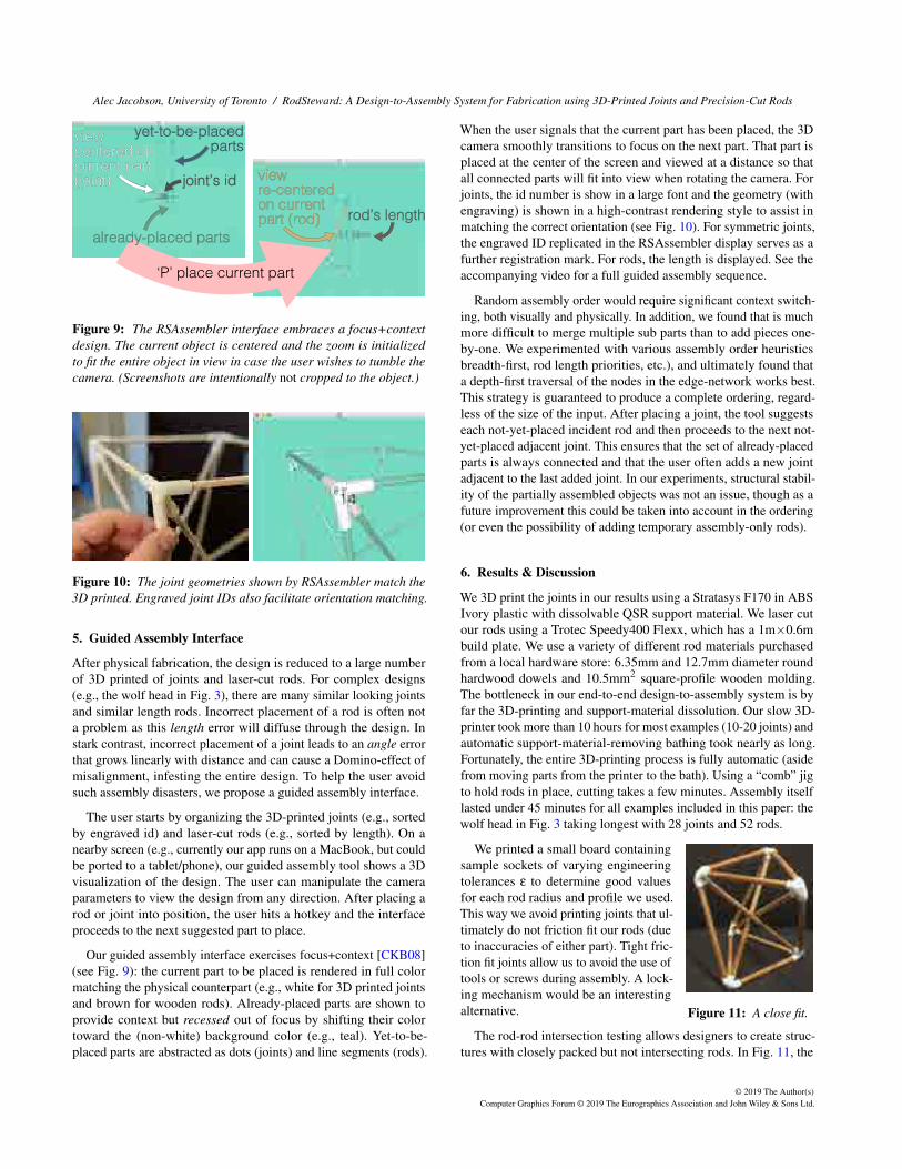
view centered on current part (joint) joint’s id
already-placed parts
yet-to-be-placedparts
view re-centered on current part (rod) rod’s length
‘P’ place current part
Figure 9: The RSAssembler interface embraces a focus+contextdesign. The current object is centered and the zoom is initializedto fit the entire object in view in case the user wishes to tumble thecamera. (Screenshots are intentionally not cropped to the object.)
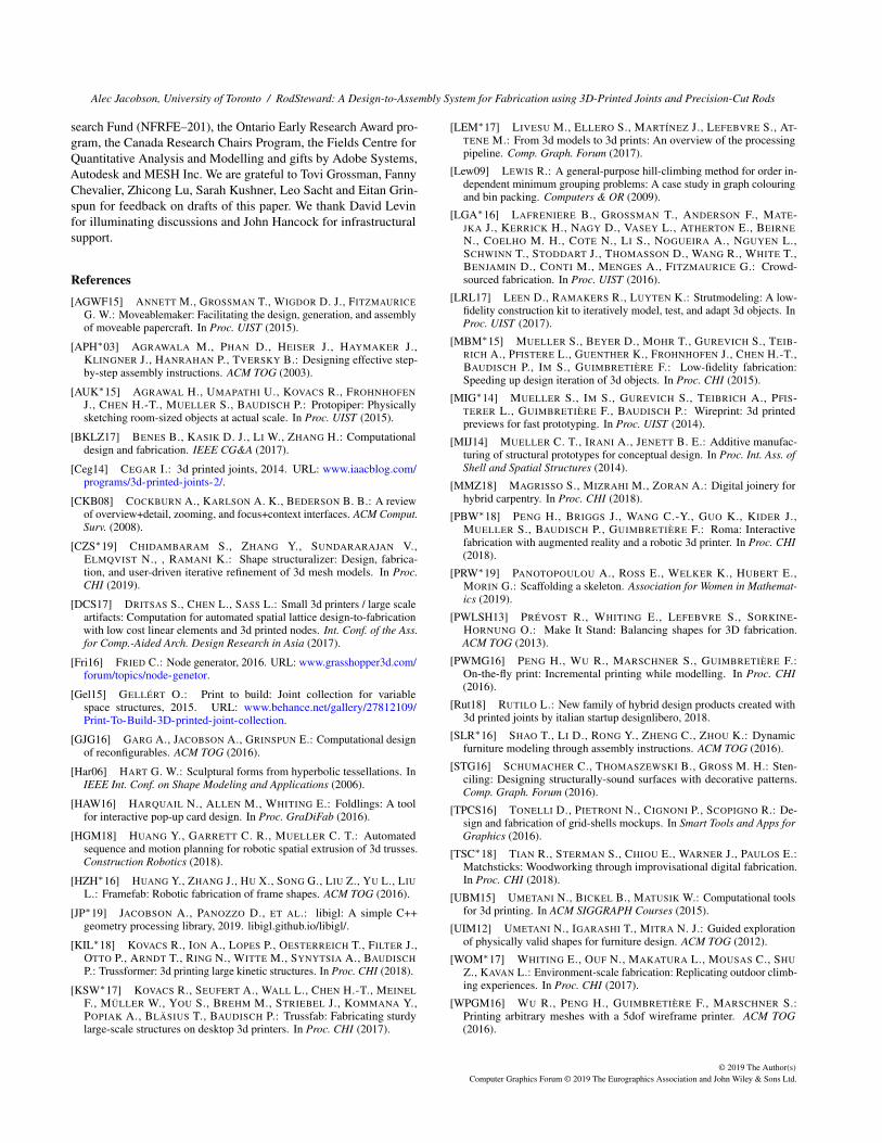
Figure 10: The joint geometries shown by RSAssembler match the3D printed. Engraved joint IDs also facilitate orientation matching.
5. Guided Assembly Interface
After physical fabrication, the design is reduced to a large numberof 3D printed of joints and laser-cut rods. For complex designs(e.g., the wolf head in Fig. 3), there are many similar looking jointsand similar length rods. Incorrect placement of a rod is often nota problem as this length error will diffuse through the design. Instark contrast, incorrect placement of a joint leads to an angle errorthat grows linearly with distance and can cause a Domino-effect ofmisalignment, infesting the entire design. To help the user avoidsuch assembly disasters, we propose a guided assembly interface.
The user starts by organizing the 3D-printed joints (e.g., sortedby engraved id) and laser-cut rods (e.g., sorted by length). On anearby screen (e.g., currently our app runs on a MacBook, but couldbe ported to a tablet/phone), our guided assembly tool shows a 3Dvisualization of the design. The user can manipulate the cameraparameters to view the design from any direction. After placing arod or joint into position, the user hits a hotkey and the interfaceproceeds to the next suggested part to place.
Our guided assembly interface exercises focus+context [CKB08](see Fig. 9): the current part to be placed is rendered in full colormatching the physical counterpart (e.g., white for 3D printed jointsand brown for wooden rods). Already-placed parts are shown toprovide context but recessed out of focus by shifting their colortoward the (non-white) background color (e.g., teal). Yet-to-be-placed parts are abstracted as dots (joints) and line segments (rods).
When the user signals that the current part has been placed, the 3Dcamera smoothly transitions to focus on the next part. That part isplaced at the center of the screen and viewed at a distance so thatall connected parts will fit into view when rotating the camera. Forjoints, the id number is show in a large font and the geometry (withengraving) is shown in a high-contrast rendering style to assist inmatching the correct orientation (see Fig. 10). For symmetric joints,the engraved ID replicated in the RSAssembler display serves as afurther registration mark. For rods, the length is displayed. See theaccompanying video for a full guided assembly sequence.
Random assembly order would require significant context switch-ing, both visually and physically. In addition, we found that is muchmore difficult to merge multiple sub parts than to add pieces one-by-one. We experimented with various assembly order heuristicsbreadth-first, rod length priorities, etc.), and ultimately found thata depth-first traversal of the nodes in the edge-network works best.This strategy is guaranteed to produce a complete ordering, regard-less of the size of the input. After placing a joint, the tool suggestseach not-yet-placed incident rod and then proceeds to the next not-yet-placed adjacent joint. This ensures that the set of already-placedparts is always connected and that the user often adds a new jointadjacent to the last added joint. In our experiments, structural stabil-ity of the partially assembled objects was not an issue, though as afuture improvement this could be taken into account in the ordering(or even the possibility of adding temporary assembly-only rods).
6. Results & Discussion
We 3D print the joints in our results using a Stratasys F170 in ABSIvory plastic with dissolvable QSR support material. We laser cutour rods using a Trotec Speedy400 Flexx, which has a 1m×0.6mbuild plate. We use a variety of different rod materials purchasedfrom a local hardware store: 6.35mm and 12.7mm diameter roundhardwood dowels and 10.5mm2 square-profile wooden molding.The bottleneck in our end-to-end design-to-assembly system is byfar the 3D-printing and support-material dissolution. Our slow 3D-printer took more than 10 hours for most examples (10-20 joints) andautomatic support-material-removing bathing took nearly as long.Fortunately, the entire 3D-printing process is fully automatic (asidefrom moving parts from the printer to the bath). Using a “comb” jigto hold rods in place, cutting takes a few minutes. Assembly itselflasted under 45 minutes for all examples included in this paper: thewolf head in Fig. 3 taking longest with 28 joints and 52 rods.
Figure 11: A close fit.
We printed a small board containingsample sockets of varying engineeringtolerances ε to determine good valuesfor each rod radius and profile we used.This way we avoid printing joints that ul-timately do not friction fit our rods (dueto inaccuracies of either part). Tight fric-tion fit joints allow us to avoid the use oftools or screws during assembly. A lock-ing mechanism would be an interestingalternative.
The rod-rod intersection testing allows designers to create struc-tures with closely packed but not intersecting rods. In Fig. 11, the
© 2019 The Author(s)Computer Graphics Forum © 2019 The Eurographics Association and John Wiley & Sons Ltd.

Alec Jacobson, University of Toronto / RodSteward: A Design-to-Assembly System for Fabrication using 3D-Printed Joints and Precision-Cut Rods
Scale by 50%
same 3D-printed joints, different rod lengths
Figure 12: Isotropic scaling the design will not change the jointgeometry, so the same 3D prints may be reused at different scales.
triangular prism shape was twist just until a collision occurred. In-deed, the assembled rods are nearly touching. Finding designs likethis without a virtual real-time feedback interface like RSDesignerwould be tedious and difficult.
An interesting design feature that serendipitously emerged fromexploring in RSDesigner is that when scaling the node positionsisotropically, the joint geometry remains identical: only the rodsshrink/grow uniformly. This informs us that the same 3D printedjoints can be used to create different scales of the same object: justreplace the rods. We realized this feature in the lamp design inFig. 12. A 1.4m-tall lamp is first constructed, then all rods are cut inhalf and the lamp is reassembled as a 0.7m-tall lamp.
Figure 13: This tailored coffeetable inherits the strength of hard-wood dowels to supports not onlyitself, but also top panel and laptop(table in daily use for six months).
We do not perform finite-element analysis or optimizethe design for structural stabil-ity beyond balance. Nonethe-less the structures we cre-ate are sturdy, inheriting thestrength of the wooden rods.In Fig. 13, we demonstrate aminimalist coffee-table design.This table is now in regular useat an office environment.
Disassembled, our struc-tures are compact (see Fig. 1).Rods can be cut from standard-size dowels. Transportationcould be as simple as shipping the joints and cutting rods on site.Although circular-profile dowels are the most common and cheap-est rods purchased at a hardware store, our entire system supportspolygonal profile rods. In Fig. 14, a decorative bowl is designedusing square-profile molding for rods.
Unlike cheap, mass-manufactured guitar stand, the unique de-sign shown in Fig. 1 represents an aesthetic discovered by the userduring modeling. The interface tools and on-the-fly evaluation ofRSDesigner allow a user to fine tune a design in a tight loop.
7. Limitations & Future Work
Our design-to-assembly workflow is not without limitations. Wefocused on mainly furniture-scale results; although our tools will
interactive design guided assembly result
Figure 14: The square-profile of the rods in this design affect notjust the appearance but also the constructed joint geometries.
function correctly at any scale, the size of the structure is bound onthe small end by the precision of the 3D printer and on the end bythe length of the largest rod. We have also left various incrementalimprovements to design space as future work: e.g., non-regularconvex polygon profiles, varying the rod radius r across edges,varying thickness σ across joints, adding point loads to adjust thecenter-of-mass. We are intrigued by the idea of adding fine-scaledecorative patterns [STG16] or Voronoi duals [MMZ18] to ourjoint geometries. Very large or volume-filling designs (e.g., trusses)might raise performance concerns and require a dynamic bounding-volume hierarchy (cf. [GJG16]) for intersection testing etc. Ourassemblies only required a single person guided by RSAssembler.We forgo a formal user study to confirm that guided assembly isbetter than having no assembly instructions [KSW∗17] or a staticplan [TPCS16]. It would be interesting to use crowds or robots tobuild architectural scale structures à la Lafreniere et al. [LGA∗16].
If we idealize the joints and rods as perfectly rigid objects, thenall our results are mathematically impossible to assemble. We arereliant on compliance. For our sparse, 1D structures reachabilitywas not a major concern (cf. panel-based structures, [UIM12]).
The full power of the laser cutter was not truly leveraged. Weuse the laser cutter out of availability (we have one), convenience(easier than sawing), and efficiency (faster, too). For the results here,a robotic rod cutter might be more appropriate. In future work, itwould be interesting to exploit at least the two-dimensional capabili-ties of laser cutting in conjunction with our interfaces.
While our lamps and coffee tables can withstand light externalloads, larger furniture or structural shapes require consideration oftheir use and environment [UIM12, WOM∗17]. In future work, wewould like to consider structural properties of joints [MIJ14] anddirectly incorporate loads from non-trivial contact and friction withexternal objects into our design tool (i.e., beyond the point loadsof [UIM12]). We have already entertained interest from architects
Figure 15: RodSteward could ex-tend design-to-assembly beyondfurniture: a rendered pavilion.
to adapt our joint generation forarchitectural-scale objects (see,e.g., Fig. 15). We are excitedby the recent work of Yoshidaet al. [YLI19], who build struc-tures out of found tree branches.Curved or arbitrarily shapedrods could be another directionfor future research.
Acknowledgements
This research is funded in part by NSERC Discovery (RG-PIN2017–05235, RGPAS–2017–507938), New Frontiers of Re-
© 2019 The Author(s)Computer Graphics Forum © 2019 The Eurographics Association and John Wiley & Sons Ltd.
Alec Jacobson, University of Toronto / RodSteward: A Design-to-Assembly System for Fabrication using 3D-Printed Joints and Precision-Cut Rods
search Fund (NFRFE–201), the Ontario Early Research Award pro-gram, the Canada Research Chairs Program, the Fields Centre forQuantitative Analysis and Modelling and gifts by Adobe Systems,Autodesk and MESH Inc. We are grateful to Tovi Grossman, FannyChevalier, Zhicong Lu, Sarah Kushner, Leo Sacht and Eitan Grin-spun for feedback on drafts of this paper. We thank David Levinfor illuminating discussions and John Hancock for infrastructuralsupport.
References
[AGWF15] ANNETT M., GROSSMAN T., WIGDOR D. J., FITZMAURICEG. W.: Moveablemaker: Facilitating the design, generation, and assemblyof moveable papercraft. In Proc. UIST (2015).
[APH∗03] AGRAWALA M., PHAN D., HEISER J., HAYMAKER J.,KLINGNER J., HANRAHAN P., TVERSKY B.: Designing effective step-by-step assembly instructions. ACM TOG (2003).
[AUK∗15] AGRAWAL H., UMAPATHI U., KOVACS R., FROHNHOFENJ., CHEN H.-T., MUELLER S., BAUDISCH P.: Protopiper: Physicallysketching room-sized objects at actual scale. In Proc. UIST (2015).
[BKLZ17] BENES B., KASIK D. J., LI W., ZHANG H.: Computationaldesign and fabrication. IEEE CG&A (2017).
[Ceg14] CEGAR I.: 3d printed joints, 2014. URL: www.iaacblog.com/programs/3d-printed-joints-2/.
[CKB08] COCKBURN A., KARLSON A. K., BEDERSON B. B.: A reviewof overview+detail, zooming, and focus+context interfaces. ACM Comput.Surv. (2008).
[CZS∗19] CHIDAMBARAM S., ZHANG Y., SUNDARARAJAN V.,ELMQVIST N., , RAMANI K.: Shape structuralizer: Design, fabrica-tion, and user-driven iterative refinement of 3d mesh models. In Proc.CHI (2019).
[DCS17] DRITSAS S., CHEN L., SASS L.: Small 3d printers / large scaleartifacts: Computation for automated spatial lattice design-to-fabricationwith low cost linear elements and 3d printed nodes. Int. Conf. of the Ass.for Comp.-Aided Arch. Design Research in Asia (2017).
[Fri16] FRIED C.: Node generator, 2016. URL: www.grasshopper3d.com/forum/topics/node-genetor.
[Gel15] GELLÉRT O.: Print to build: Joint collection for variablespace structures, 2015. URL: www.behance.net/gallery/27812109/Print-To-Build-3D-printed-joint-collection.
[GJG16] GARG A., JACOBSON A., GRINSPUN E.: Computational designof reconfigurables. ACM TOG (2016).
[Har06] HART G. W.: Sculptural forms from hyperbolic tessellations. InIEEE Int. Conf. on Shape Modeling and Applications (2006).
[HAW16] HARQUAIL N., ALLEN M., WHITING E.: Foldlings: A toolfor interactive pop-up card design. In Proc. GraDiFab (2016).
[HGM18] HUANG Y., GARRETT C. R., MUELLER C. T.: Automatedsequence and motion planning for robotic spatial extrusion of 3d trusses.Construction Robotics (2018).
[HZH∗16] HUANG Y., ZHANG J., HU X., SONG G., LIU Z., YU L., LIUL.: Framefab: Robotic fabrication of frame shapes. ACM TOG (2016).
[JP∗19] JACOBSON A., PANOZZO D., ET AL.: libigl: A simple C++geometry processing library, 2019. libigl.github.io/libigl/.
[KIL∗18] KOVACS R., ION A., LOPES P., OESTERREICH T., FILTER J.,OTTO P., ARNDT T., RING N., WITTE M., SYNYTSIA A., BAUDISCHP.: Trussformer: 3d printing large kinetic structures. In Proc. CHI (2018).
[KSW∗17] KOVACS R., SEUFERT A., WALL L., CHEN H.-T., MEINELF., MÜLLER W., YOU S., BREHM M., STRIEBEL J., KOMMANA Y.,POPIAK A., BLÄSIUS T., BAUDISCH P.: Trussfab: Fabricating sturdylarge-scale structures on desktop 3d printers. In Proc. CHI (2017).
[LEM∗17] LIVESU M., ELLERO S., MARTÍNEZ J., LEFEBVRE S., AT-TENE M.: From 3d models to 3d prints: An overview of the processingpipeline. Comp. Graph. Forum (2017).
[Lew09] LEWIS R.: A general-purpose hill-climbing method for order in-dependent minimum grouping problems: A case study in graph colouringand bin packing. Computers & OR (2009).
[LGA∗16] LAFRENIERE B., GROSSMAN T., ANDERSON F., MATE-JKA J., KERRICK H., NAGY D., VASEY L., ATHERTON E., BEIRNEN., COELHO M. H., COTE N., LI S., NOGUEIRA A., NGUYEN L.,SCHWINN T., STODDART J., THOMASSON D., WANG R., WHITE T.,BENJAMIN D., CONTI M., MENGES A., FITZMAURICE G.: Crowd-sourced fabrication. In Proc. UIST (2016).
[LRL17] LEEN D., RAMAKERS R., LUYTEN K.: Strutmodeling: A low-fidelity construction kit to iteratively model, test, and adapt 3d objects. InProc. UIST (2017).
[MBM∗15] MUELLER S., BEYER D., MOHR T., GUREVICH S., TEIB-RICH A., PFISTERE L., GUENTHER K., FROHNHOFEN J., CHEN H.-T.,BAUDISCH P., IM S., GUIMBRETIÈRE F.: Low-fidelity fabrication:Speeding up design iteration of 3d objects. In Proc. CHI (2015).
[MIG∗14] MUELLER S., IM S., GUREVICH S., TEIBRICH A., PFIS-TERER L., GUIMBRETIÈRE F., BAUDISCH P.: Wireprint: 3d printedpreviews for fast prototyping. In Proc. UIST (2014).
[MIJ14] MUELLER C. T., IRANI A., JENETT B. E.: Additive manufac-turing of structural prototypes for conceptual design. In Proc. Int. Ass. ofShell and Spatial Structures (2014).
[MMZ18] MAGRISSO S., MIZRAHI M., ZORAN A.: Digital joinery forhybrid carpentry. In Proc. CHI (2018).
[PBW∗18] PENG H., BRIGGS J., WANG C.-Y., GUO K., KIDER J.,MUELLER S., BAUDISCH P., GUIMBRETIÈRE F.: Roma: Interactivefabrication with augmented reality and a robotic 3d printer. In Proc. CHI(2018).
[PRW∗19] PANOTOPOULOU A., ROSS E., WELKER K., HUBERT E.,MORIN G.: Scaffolding a skeleton. Association for Women in Mathemat-ics (2019).
[PWLSH13] PRÉVOST R., WHITING E., LEFEBVRE S., SORKINE-HORNUNG O.: Make It Stand: Balancing shapes for 3D fabrication.ACM TOG (2013).
[PWMG16] PENG H., WU R., MARSCHNER S., GUIMBRETIÈRE F.:On-the-fly print: Incremental printing while modelling. In Proc. CHI(2016).
[Rut18] RUTILO L.: New family of hybrid design products created with3d printed joints by italian startup designlibero, 2018.
[SLR∗16] SHAO T., LI D., RONG Y., ZHENG C., ZHOU K.: Dynamicfurniture modeling through assembly instructions. ACM TOG (2016).
[STG16] SCHUMACHER C., THOMASZEWSKI B., GROSS M. H.: Sten-ciling: Designing structurally-sound surfaces with decorative patterns.Comp. Graph. Forum (2016).
[TPCS16] TONELLI D., PIETRONI N., CIGNONI P., SCOPIGNO R.: De-sign and fabrication of grid-shells mockups. In Smart Tools and Apps forGraphics (2016).
[TSC∗18] TIAN R., STERMAN S., CHIOU E., WARNER J., PAULOS E.:Matchsticks: Woodworking through improvisational digital fabrication.In Proc. CHI (2018).
[UBM15] UMETANI N., BICKEL B., MATUSIK W.: Computational toolsfor 3d printing. In ACM SIGGRAPH Courses (2015).
[UIM12] UMETANI N., IGARASHI T., MITRA N. J.: Guided explorationof physically valid shapes for furniture design. ACM TOG (2012).
[WOM∗17] WHITING E., OUF N., MAKATURA L., MOUSAS C., SHUZ., KAVAN L.: Environment-scale fabrication: Replicating outdoor climb-ing experiences. In Proc. CHI (2017).
[WPGM16] WU R., PENG H., GUIMBRETIÈRE F., MARSCHNER S.:Printing arbitrary meshes with a 5dof wireframe printer. ACM TOG(2016).
© 2019 The Author(s)Computer Graphics Forum © 2019 The Eurographics Association and John Wiley & Sons Ltd.

Alec Jacobson, University of Toronto / RodSteward: A Design-to-Assembly System for Fabrication using 3D-Printed Joints and Precision-Cut Rods
[YIO∗15] YOSHIDA H., IGARASHI T., OBUCHI Y., TAKAMI Y., SATOJ., ARAKI M., MIKI M., NAGATA K., SAKAI K., IGARASHI S.:Architecture-scale human-assisted additive manufacturing. ACM TOG(2015).
[YLI19] YOSHIDA H., LARSSON M., IGARASHI T.: Upcycling treebranches as architectural elements through collaborative design and fabri-cation. In Proc. TEI (2019).
[ZGZJ16] ZHOU Q., GRINSPUN E., ZORIN D., JACOBSON A.: Mesharrangements for solid geometry. ACM TOG (2016).
[Zho19] ZHOU Q.: Pymesh, 2019. URL: pymesh.readthedocs.io.
[ZLP∗15] ZHANG X., LE X., PANOTOPOULOU A., WHITING E., WANGC. C. L.: Perceptual models of preference in 3d printing direction. ACMTOG (2015).
Appendix A: 3D-Printable Solid Joint Geometry
overlapping rods
zero offset joints
constant offsetjoints
r + ε}r +
ε
σ
h
gij
vi
}
}
}}θijk {i, j}
{i, k}
our variableoffset joints
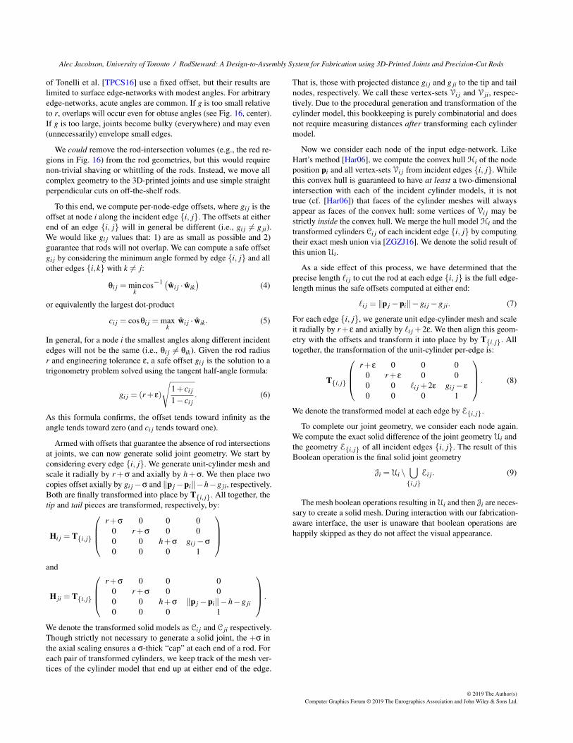
Figure 16: Previous joint geome-try generation methods do not con-sider the possibility of rod intersec-tions at joints. A per-edge offset isnecessary and can be minimizedon a case-by-case basis.
The input to our geometry con-struction algorithm is a 3Dedge-network, i.e., a graph em-bedded in R3, composed of alist of n node positions pi ∈R3 for i ∈ {1, . . . ,n} and a listof m undirected edges as pairs{i, j} ∈ {1, . . . ,n}2 where weuse the equivalence relation{i, j}= { j, i}.
In this technical section, weuse subscript notation suchthat a{i, j} = a{ j,i} refers toa quantity associated withthe undirected edge {i, j},whereas bi j refers to a quantityassociated with end-point i onthe edge {i, j} and in generalbi j 6= b ji. In most cases, thedifference will also be clearfrom context.
The algorithm is controlledby a number of user-definedparameters (see Fig. 16, right):r the radius of the rods, pthe number of sides on thepolygonal cross-sectional pro-file of the rods (without lossof generality, we will assumethese polygons are regularlyshaped), σ the thickness of the3D-printed joints encasing each node, h the amount that joints over-hang along incident rods, and ε the “engineering tolerance” (possiblynegative for friction fitting) between the joints and rods.
The output of our method includes n solid meshes representingthe surfaces of the 3D-printable joint geometry at each node andm precise rod lengths to cut. As seen in Fig. 16, the physicallyrealizable length of the rod of each edge {i, j} will generally be lessthan the raw edge length (‖pi−p j‖). Instead, the precise lengthswill be implicitly determined by the geometry of the joints at eithernode.
✘ ✓
mismatching joint orientations our consistent joint orientations
Figure 17: Direct extensions of wiremeshing algorithms (e.g.,[PRW∗19, Har06]) may result in twisting along edges, leading toinconsistent rod-orientations at either end. Our joint-constructionalgorithm avoids this.
The geometry of the joint at each node will be an independentsolid object, but we require that the outlets at either joint incidenton an edge to be consistent so that polygonal-cross-section rodgeometry can be rotated to fit either end Fig. 17.
A useful subroutine is to generate the primitive geometry of asolid mesh of a generalized cylinder with the profile of a p-sidedpolygon. This is accomplished by extruding a regular p-gon in-scribed in the unit circle of the xy plane along the z-axis for oneunit.
This unit-cylinder mesh geometry can then be transformed tolie along any given edge. For each edge {i, j}, we compute a 3Drotation R{i, j} ∈ SO(3) aligning the z-axis vector ez = (0,0,1)> to
its unit edge vector wi j = (p j−pi)>/‖p j−pi‖:
R{i, j} = I+[ez× wi j]×+1
1+ ez · wi j[ez× wi j]
2× (1)
where I ∈ R3×3 is the identity matrix and [x]× is the matrix repre-senting cross-product by the vector x:
[x]× =
0 −x3 x2x3 0 −x1−x2 x1 0
. (2)
We could place rod geometry along each edge {i, j} by compos-ing this per-edge rotation with anisotropic pre-scaling along thez-axis by the edge length ‖p j−pi‖ and radially in the xy-plane bythe desired radius r and a post-translation to the edge tip position pi.As a per-edge affine transformation:
(I pi
0 0 0 1
) R{i, j}000
0 0 0 1
︸ ︷︷ ︸
T{i, j}
r 0 0 00 r 0 00 0 ‖p j−pi‖ 00 0 0 1
, (3)
where T{i, j} ∈ R4×4 is a rigid transformation placing the rod intothe edge-network. However, this naïve rod geometry will result inmessy intersections at each node (see Fig. 16, left). In the physicalworld, we can not allow the rods of multiple edges incident on a nodeto “share” the space at that node. Offsetting by a uniform amountg (cf. [Har06]) works when g is large relative to r and the anglesbetween incident rods are not very acute. The 3D-printed joints
© 2019 The Author(s)Computer Graphics Forum © 2019 The Eurographics Association and John Wiley & Sons Ltd.
Alec Jacobson, University of Toronto / RodSteward: A Design-to-Assembly System for Fabrication using 3D-Printed Joints and Precision-Cut Rods
of Tonelli et al. [TPCS16] use a fixed offset, but their results arelimited to surface edge-networks with modest angles. For arbitraryedge-networks, acute angles are common. If g is too small relativeto r, overlaps will occur even for obtuse angles (see Fig. 16, center).If g is too large, joints become bulky (everywhere) and may even(unnecessarily) envelope small edges.
We could remove the rod-intersection volumes (e.g., the red re-gions in Fig. 16) from the rod geometries, but this would requirenon-trivial shaving or whittling of the rods. Instead, we move allcomplex geometry to the 3D-printed joints and use simple straightperpendicular cuts on off-the-shelf rods.
To this end, we compute per-node-edge offsets, where gi j is theoffset at node i along the incident edge {i, j}. The offsets at eitherend of an edge {i, j} will in general be different (i.e., gi j 6= g ji).We would like gi j values that: 1) are as small as possible and 2)guarantee that rods will not overlap. We can compute a safe offsetgi j by considering the minimum angle formed by edge {i, j} and allother edges {i,k} with k 6= j:
θi j = mink
cos−1 (wi j · wik)
(4)
or equivalently the largest dot-product
ci j = cosθi j = maxk
wi j · wik. (5)
In general, for a node i the smallest angles along different incidentedges will not be the same (i.e., θi j 6= θik). Given the rod radiusr and engineering tolerance ε, a safe offset gi j is the solution to atrigonometry problem solved using the tangent half-angle formula:
gi j = (r+ ε)
√1+ ci j
1− ci j. (6)
As this formula confirms, the offset tends toward infinity as theangle tends toward zero (and ci j tends toward one).
Armed with offsets that guarantee the absence of rod intersectionsat joints, we can now generate solid joint geometry. We start byconsidering every edge {i, j}. We generate unit-cylinder mesh andscale it radially by r+σ and axially by h+σ. We then place twocopies offset axially by gi j−σ and ‖p j−pi‖−h−g ji, respectively.Both are finally transformed into place by T{i, j}. All together, thetip and tail pieces are transformed, respectively, by:
Hi j = T{i, j}
r+σ 0 0 0
0 r+σ 0 00 0 h+σ gi j−σ
0 0 0 1
and
H ji = T{i, j}
r+σ 0 0 0
0 r+σ 0 00 0 h+σ ‖p j−pi‖−h−g ji0 0 0 1
.
We denote the transformed solid models as Ci j and C ji respectively.Though strictly not necessary to generate a solid joint, the +σ inthe axial scaling ensures a σ-thick “cap” at each end of a rod. Foreach pair of transformed cylinders, we keep track of the mesh ver-tices of the cylinder model that end up at either end of the edge.
That is, those with projected distance gi j and g ji to the tip and tailnodes, respectively. We call these vertex-sets Vi j and V ji, respec-tively. Due to the procedural generation and transformation of thecylinder model, this bookkeeping is purely combinatorial and doesnot require measuring distances after transforming each cylindermodel.
Now we consider each node of the input edge-network. LikeHart’s method [Har06], we compute the convex hull Hi of the nodeposition pi and all vertex-sets Vi j from incident edges {i, j}. Whilethis convex hull is guaranteed to have at least a two-dimensionalintersection with each of the incident cylinder models, it is nottrue (cf. [Har06]) that faces of the cylinder meshes will alwaysappear as faces of the convex hull: some vertices of Vi j may bestrictly inside the convex hull. We merge the hull model Hi and thetransformed cylinders Ci j of each incident edge {i, j} by computingtheir exact mesh union via [ZGZJ16]. We denote the solid result ofthis union Ui.
As a side effect of this process, we have determined that theprecise length `i j to cut the rod at each edge {i, j} is the full edge-length minus the safe offsets computed at either end:
`i j = ‖p j−pi‖−gi j−g ji. (7)
For each edge {i, j}, we generate unit edge-cylinder mesh and scaleit radially by r+ ε and axially by `i j +2ε. We then align this geom-etry with the offsets and transform it into place by by T{i, j}. Alltogether, the transformation of the unit-cylinder per-edge is:
T{i, j}
r+ ε 0 0 0
0 r+ ε 0 00 0 `i j +2ε gi j− ε
0 0 0 1
. (8)
We denote the transformed model at each edge by E{i, j}.
To complete our joint geometry, we consider each node again.We compute the exact solid difference of the joint geometry Ui andthe geometry E{i, j} of all incident edges {i, j}. The result of thisBoolean operation is the final solid joint geometry
Ji = Ui \⋃{i, j}
Ei j. (9)
The mesh boolean operations resulting in Ui and then Ji are neces-sary to create a solid mesh. During interaction with our fabrication-aware interface, the user is unaware that boolean operations arehappily skipped as they do not affect the visual appearance.
© 2019 The Author(s)Computer Graphics Forum © 2019 The Eurographics Association and John Wiley & Sons Ltd.