robust indexable profi le mills with new ball end mills for
TRANSCRIPT

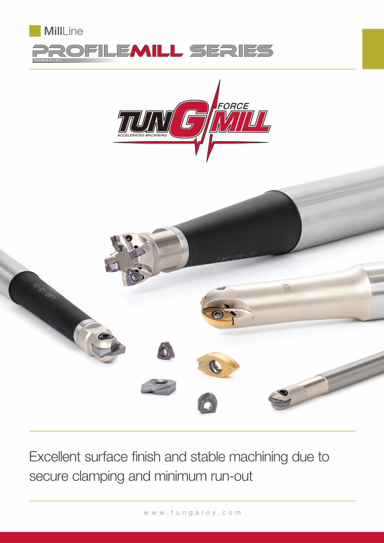
MillLine
Profilemill seriesTungaloy Report No. 528-G
w w w . t u n g a l o y . c o m
Robust indexable profi le mills with new ball end mills for rough profi ling
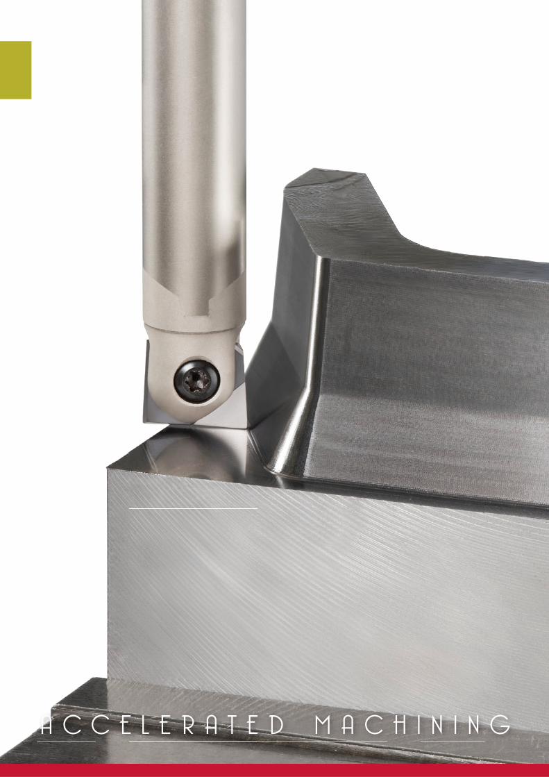
A C C E L E R A T E D M A C H I N I N G
MillLine
Profilemill series
w w w . t u n g a l o y . c o m
Excellent surface fi nish and stable machining due to
secure clamping and minimum run-out
4 PROFILEMILL-SERIES
Profilemill series
New
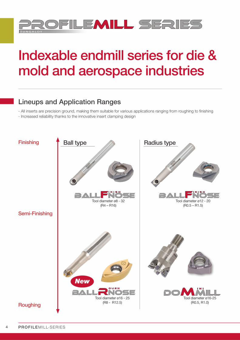
Indexable endmill series for die & mold and aerospace industries
- All inserts are precision ground, making them suitable for various applications ranging from roughing to finishing
- Increased reliability thanks to the innovative insert clamping design
Lineups and Application Ranges
Finishing Ball type Radius type
Tool diameter ø8 - 32
(R4 – R16)
Tool diameter ø16 - 25
(R8 - R12.5)
Semi-Finishing
Roughing
Tool diameter ø12 - 20
(R0.5 – R1.5)
Tool diameter ø16-25
(R0.5, R1.0)
5
New
w w w . t u n g a l o y . c o m
A CC E L E R A T E D M A C H I N I N G
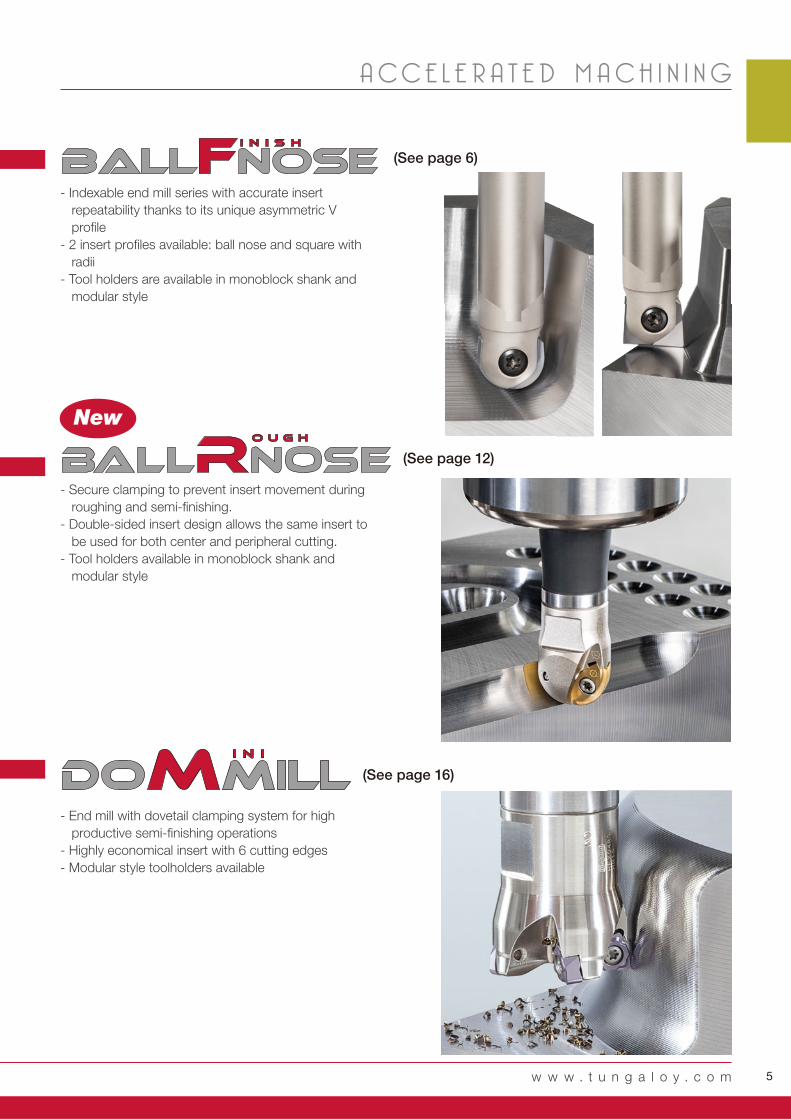
- Indexable end mill series with accurate insert
repeatability thanks to its unique asymmetric V
profile
- 2 insert profiles available: ball nose and square with
radii
- Tool holders are available in monoblock shank and
modular style
- Secure clamping to prevent insert movement during
roughing and semi-finishing.
- Double-sided insert design allows the same insert to
be used for both center and peripheral cutting.
- Tool holders available in monoblock shank and
modular style
- End mill with dovetail clamping system for high
productive semi-finishing operations
- Highly economical insert with 6 cutting edges
- Modular style toolholders available
(See page 6)
(See page 12)
(See page 16)
6 PROFILEMILL-SERIES
Profilemill series
F F
F
R R R
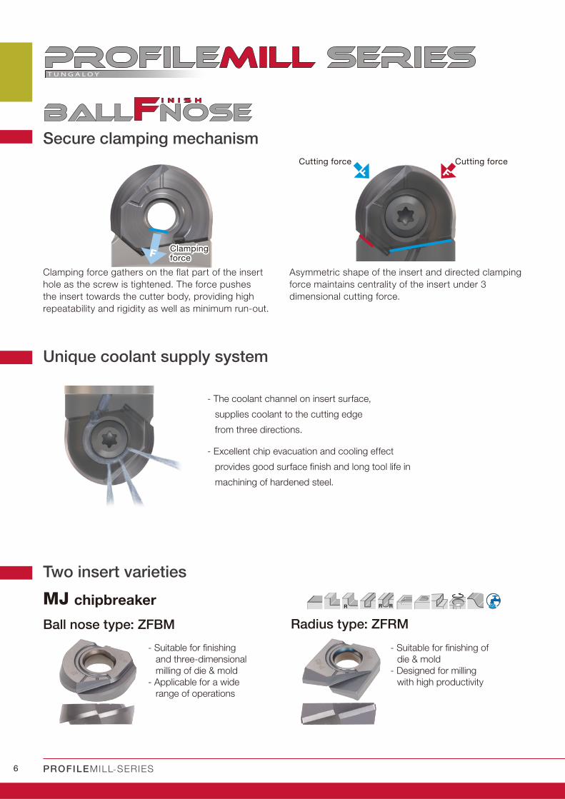
Secure clamping mechanism
Asymmetric shape of the insert and directed clamping
force maintains centrality of the insert under 3
dimensional cutting force.
- The coolant channel on insert surface,
supplies coolant to the cutting edge
from three directions.
- Excellent chip evacuation and cooling effect
provides good surface finish and long tool life in
machining of hardened steel.
Clamping force gathers on the flat part of the insert
hole as the screw is tightened. The force pushes
the insert towards the cutter body, providing high
repeatability and rigidity as well as minimum run-out.
Unique coolant supply system
Two insert varieties
MJ chipbreaker
Ball nose type: ZFBM Radius type: ZFRM
- Suitable for fi nishing
and three-dimensional
milling of die & mold
- Applicable for a wide
range of operations
- Suitable for fi nishing of
die & mold
- Designed for milling
with high productivity
Cutting force
Clamping Clamping forceforce
Cutting force
7
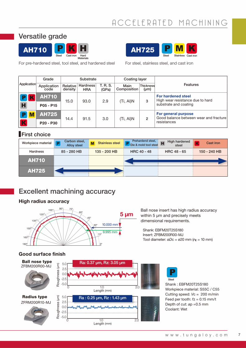
AH710 AH725
AH71015.0 93.0 2.9 (Ti, Al)N 3
P05 - P15
AH72514.4 91.5 3.0 (Ti, Al)N 2
P20 - P30
85 - 280 HB 135 - 200 HB HRC 40 - 48 HRC 48 - 65 150 - 240 HB
AH710
AH725
5.0
2.5
0.0
-2.5
-5.0
5.0
2.5
0.0
-2.5
-5.0
0 1.0 2.0
0 1.0 2.0
5 µm
10.000 mm
9.995 mm
Ra : 0.25 μm, Rz : 1.43 μm
Ra: 0.37 μm, Rz: 3.05 μmZFBM200R00-MJ
ZFRM200R10-MJ
w w w . t u n g a l o y . c o m
A CC E L E R A T E D M A C H I N I N G
Versatile grade
For general purposeGood balance between wear and fracture resistances
For hardened steelHigh wear resistance due to hard substrate and coating
Excellent machining accuracy
Shank: EBFM20T25S180
Insert: ZFBM200R00-MJ
Tool diameter: øDc = ø20 mm (rε = 10 mm)
Ball nose insert has high radius accuracy
within 5 μm and precisely meets
dimensional requirements.
For pre-hardened steel, tool steel, and hardened steel For steel, stainless steel, and cast iron
StainlessSteel Cast iron
Application Features
Grade Substrate Coating layer
Applicationcode
Relative density
MainComposition
HardnessHRA
T. R. S.(GPa)
Thickness(μm)
Steel Cast iron
Hardness
Workpiece materialCarbon steel,
Alloy steelStainless steel
Prehardend steel,
Die & mold tool steelHigh hardened
steelCast iron
Ball nose type
Radius type
Shank : EBFM20T25S180
Workpiece material: S55C / C55
Cutting speed: Vc = 200 m/min
Feed per tooth: fz = 0.15 mm/t
Depth of cut: ap =0.5 mm
Coolant: Wet
First choice
Ro
ug
hn
ess (
μm
)R
ou
gh
ne
ss (
μm
)
Length (mm)
Length (mm)
High radius accuracy
Good surface finish
HardMaterials
Steel

8 PROFILEMILL-SERIES
Profilemill series
EBFM
DC DCONMS LS LH LF LB BHTA
EBFM08T12S100 Steel 8 12 80 20 100 10 9.5 2 ZF*M080...
EBFM08S08C100 Carbide 8 8 70 30 100 - - 1 ZF*M080...
EBFM08S08C140 Carbide 8 8 75 65 140 - - 1 ZF*M080...
EBFM10T12S100 Steel 10 12 75 25 100 15 5 2 ZF*M100...
EBFM10S10C140 Carbide 10 10 65 75 140 - - 1 ZF*M100...
EBFM10S10C220 Carbide 10 10 80 140 220 - - 1 ZF*M100...
EBFM12S12S110 Steel 12 12 80 30 110 - - 1 ZF*M120...
EBFM12S12C160 Carbide 12 12 70 90 160 - - 1 ZF*M120...
EBFM12S12C220 Carbide 12 12 70 150 220 - - 1 ZF*M120...
EBFM16T20S130 Steel 16 20 80 50 130 15.5 1.5 2 ZF*M160...
EBFM16S16C160 Carbide 16 16 80 80 160 - - 1 ZF*M160...
EBFM16S16C220 Carbide 16 16 70 150 220 - - 1 ZF*M160...
EBFM20T25S180 Steel 20 25 100 80 180 24 2.5 2 ZF*M200...
EBFM20S20C220 Carbide 20 20 100 120 220 - - 1 ZF*M200...
EBFM20S20C300 Carbide 20 20 80 220 300 - - 1 ZF*M200...
EBFM25T32S200 Steel 25 32 100 100 200 32 1.5 2 ZF*M250...
EBFM25S25C220 Carbide 25 25 100 120 220 - - 1 ZF*M250...
EBFM25S25C300 Carbide 25 25 80 220 300 - - 1 ZF*M250...
EBFM30T32S220 Steel 30 32 120 100 220 35 0.5 2 ZF*M300...
EBFM30S32C250 Carbide 30 32 100 150 250 - - 1 ZF*M300...
EBFM30S32C350 Carbide 30 32 100 250 350 - - 1 ZF*M300...
EBFM32S32S250 Steel 32 32 150 100 250 - - 1 ZF*M320...
EBFM32S32C300 Carbide 32 32 80 220 300 - - 1 ZF*M320...
EBFM08... TS 25F080A - - T-8D
EBFM10... TS 30F100A - - T-10D
EBFM12... TS 40F120A - - T-15D
EBFM16... TS 50F160A BT20S H-TB2W -
EBFM20... TS 60F200A BLDT25/M7 H-TB2W -
EBFM25... TS 70F250A BLDT25/M7 H-TB2W -
EBFM30... TS 80F300A - - T-T30
EBFM32... TS 80F300A - - T-T30
Fig. 1 Fig. 2
DC
LFLH LB
DC
ON
MS
LFLH
BHTA
DC
DC
ON
MSLS
LS
R
R R
Indexable endmil ls for high precis ion f in ish
Designation Air hole Insertmaterial Fig
withwithout
without
with
without
without
with
without
without
with
without
without
with
without
without
with
without
without
with
without
without
with
without
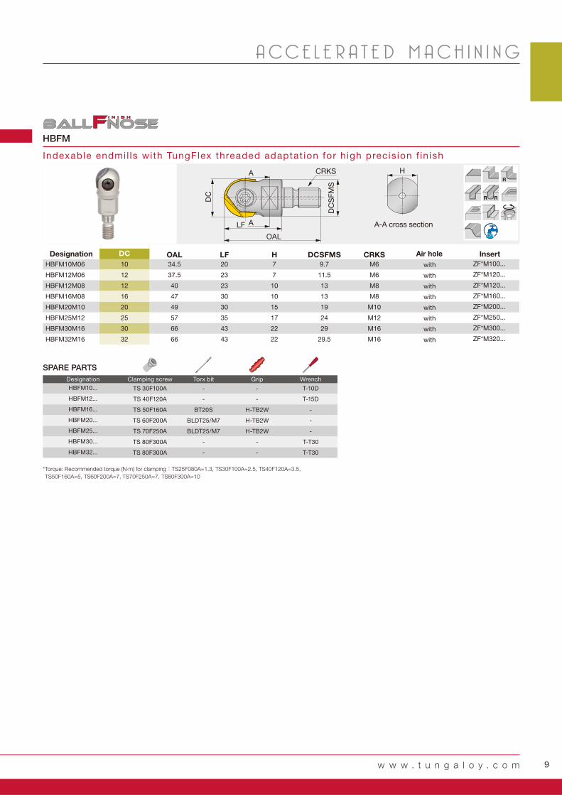
SPARE PARTS
Designation Clamping screw Torx bit Grip Wrench
*Torque: Recommended torque (N∙m) for clamping :TS25F080A=1.3, TS30F100A=2.5, TS40F120A=3.5,
TS50F160A=5, TS60F200A=7, TS70F250A=7, TS80F300A=10
9
HBFM
DC OAL LF H DCSFMS CRKS
HBFM10M06 10 34.5 20 7 9.7 M6 ZF*M100...
HBFM12M06 12 37.5 23 7 11.5 M6 ZF*M120...
HBFM12M08 12 40 23 10 13 M8 ZF*M120...
HBFM16M08 16 47 30 10 13 M8 ZF*M160...
HBFM20M10 20 49 30 15 19 M10 ZF*M200...
HBFM25M12 25 57 35 17 24 M12 ZF*M250...
HBFM30M16 30 66 43 22 29 M16 ZF*M300...
HBFM32M16 32 66 43 22 29.5 M16 ZF*M320...
A - A 断面
DC
SFM
S
LF
OAL
CRKS
DC
A
A
HR
R R
HBFM10... TS 30F100A - - T-10D
HBFM12... TS 40F120A - - T-15D
HBFM16... TS 50F160A BT20S H-TB2W -
HBFM20... TS 60F200A BLDT25/M7 H-TB2W -
HBFM25... TS 70F250A BLDT25/M7 H-TB2W -
HBFM30... TS 80F300A - - T-T30
HBFM32... TS 80F300A - - T-T30
w w w . t u n g a l o y . c o m
A CC E L E R A T E D M A C H I N I N G
Designation Air hole Insert
Indexable endmil ls with TungFlex threaded adaptat ion for high precis ion f in ish
with
with
with
with
with
with
with
with
SPARE PARTS
Designation Clamping screw Torx bit Grip Wrench
A-A cross section
*Torque: Recommended torque (N∙m) for clamping :TS25F080A=1.3, TS30F100A=2.5, TS40F120A=3.5,
TS50F160A=5, TS60F200A=7, TS70F250A=7, TS80F300A=10
10 PROFILEMILL-SERIES
Profilemill series
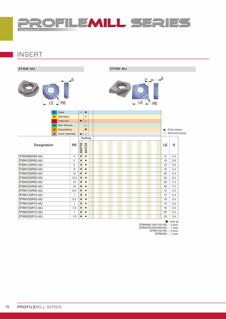
ZFBM-MJ
S
LE RE
ZFRM-MJ
3º S
LE RE
INSERT
P Steel � �
M Stainless �
K Cast iron � �
N Non-ferrous �
S Superalloys �
H Hard materials � �
Designation RE
Coating
LE S
AH
710
AH
72
5
ZFBM080R00-MJ 4 • • 8 2.4
ZFBM100R00-MJ 5 • • 10 2.9
ZFBM120R00-MJ 6 • • 12 3.4
ZFBM160R00-MJ 8 • • 16 4.4
ZFBM200R00-MJ 10 • • 20 5.4
ZFBM250R00-MJ 12.5 • • 25 6.4
ZFBM300R00-MJ 15 • • 30 7.4
ZFBM320R00-MJ 16 • • 32 7.4
ZFRM120R05-MJ 0.5 • • 12 3.4
ZFRM120R10-MJ 1 • • 12 3.4
ZFRM160R05-MJ 0.5 • • 16 4.4
ZFRM160R10-MJ 1 • • 16 4.4
ZFRM160R15-MJ 1.5 • • 16 4.4
ZFRM200R10-MJ 1 • • 20 5.4
ZFRM200R15-MJ 1.5 • • 20 5.4
: First choice : Second choice
: Line upZFBM080/100/120/160... : 5 pcs.ZFBM200/250/300/320... : 1 pcs.
ZFRM120/160... : 5 pcs.ZFRM200... : 1 pcs.

11
ISOD8 D10 D12 D16 D20 D25 D30 D32
85 - 180 HB AH725 ≤ 0.04D 180 - 260 0.15 0.2 0.2 0.25 0.25 0.3 0.35 0.35
85 - 180 HB AH710 ≤ 0.04D 180 - 260 0.15 0.2 0.2 0.25 0.25 0.3 0.35 0.35
180 - 280 HB AH725 ≤ 0.03D 150 - 230 0.15 0.2 0.2 0.25 0.25 0.3 0.35 0.35
180 - 280 HB AH710 ≤ 0.03D 180 - 230 0.15 0.2 0.2 0.25 0.25 0.3 0.35 0.35
40 - 48 HRC AH710 ≤ 0.03D 180 - 300 0.15 0.15 0.2 0.2 0.25 0.25 0.3 0.3
40 - 48 HRC AH725 ≤ 0.03D 180 - 300 0.15 0.15 0.2 0.2 0.25 0.25 0.3 0.3
135 - 200 HB AH725 ≤ 0.03D 100 - 250 0.1 0.15 0.2 0.2 0.25 0.25 0.3 0.3
150 - 240 HB AH710 ≤ 0.04D 90 - 350 0.2 0.2 0.25 0.3 0.3 0.35 0.4 0.4
150 - 240 HB AH725 ≤ 0.04D 90 - 350 0.2 0.2 0.25 0.3 0.3 0.35 0.4 0.4
- AH725 ≤ 0.03D 200 - 400 0.25 0.25 0.35 0.35 0.35 0.4 0.4 0.45
48 - 65 HRC AH710 ≤ 0.02D 50 - 180 0.08 0.08 0.1 0.13 0.15 0.2 0.2 0.25
w w w . t u n g a l o y . c o m
A CC E L E R A T E D M A C H I N I N G
Workpiece materials Grades
Feed per tooth: fz (mm/t)Max.depth of
cut(mm)
Cutting speedVc (m/min)
Hardness Priority
Low carbon steel,alloy steel
High carbon steel,alloy steel
Prehardened steelDie & mold tool steel
Stainless steel
Cast iron
Aluminium
High hardened steel
STANDARD CUTTING CONDITIONS
How to clamp the insert
1. Clear chips and dust from the pocket.
2. Place the insert in the pocket. The insert can be placed only in one direction.
3. Tighten the screw while pressing the insert into the pocket.
How to check the run-out
1. Clamp the insert on the shank.
2. Clamp the shank on a high-precision arbor.
3. Measure the run-out on tool presetter or by dial gauge.
Notes:
1. Due to the helical cutting edge, it is important that the
run-out is inspected with the insert clamped on the shank.
2. Do not use micrometer or caliper to inspect the insert diameter as inaccurate
dimensions may be provided.
· Remove excessive chip accumulation with an air blast.
· For the operation with depth of cut which varies (ex.casting skin) and
machining of workpiece materials with interrupted surface, the feed per tooth
(fz) should be set to the lower recommended value shown in the above table.
· Cutting conditions maybe limited depending on machine power, workpiece
rigidity, and spindle output. When the cutting width, depth, or overhang
length is large, set Vc and fz to the lower recommended values and check the
machine power and vibration.
First choice
For wear resistance
First choice
For wear resistance
First choice
For fracture resistance
First choice
First choice
For fracture resistance
First choice
First choice
12 PROFILEMILL-SERIES
Profilemill series
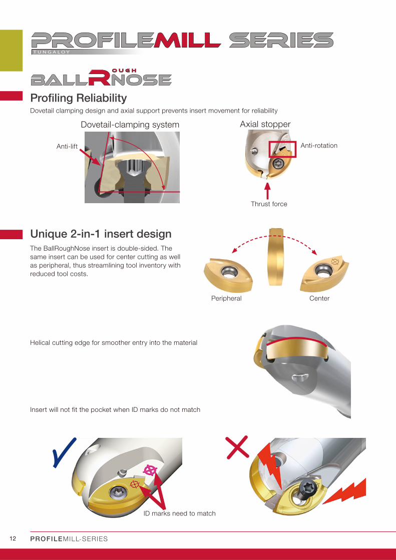
Profiling Reliability
Unique 2-in-1 insert design
Dovetail-clamping system Axial stopper
Anti-lift Anti-rotation
Thrust force
The BallRoughNose insert is double-sided. The
same insert can be used for center cutting as well
as peripheral, thus streamlining tool inventory with
reduced tool costs.
Helical cutting edge for smoother entry into the material
CenterPeripheral
Insert will not fit the pocket when ID marks do not match
ID marks need to match
Dovetail clamping design and axial support prevents insert movement for reliability
13
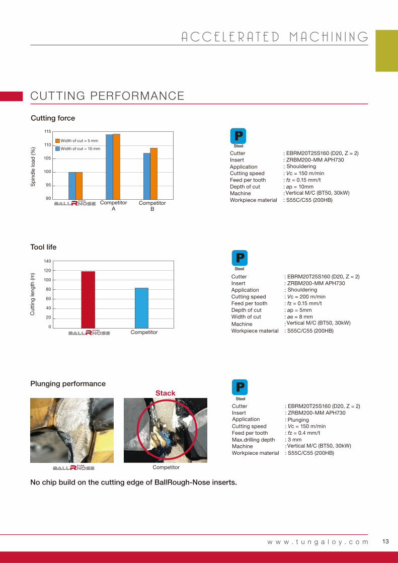
: EBRM20T25S160 (D20, Z = 2)
: ZRBM200-MM APH730
:
: Vc = 150 m/min
: fz = 0.15 mm/t
: ap = 10mm
:
: S55C/C55 (200HB)
115
110
105
100
95
90
: EBRM20T25S160 (D20, Z = 2)
: ZRBM200-MM APH730
:
: Vc = 200 m/min
: fz = 0.15 mm/t
: ap = 5mm
: ae = 8 mm
:
: S55C/C55 (200HB)
140
120
100
80
60
40
20
0
: EBRM20T25S160 (D20, Z = 2)
: ZRBM200-MM APH730
:
: Vc = 150 m/min
: fz = 0.4 mm/t
: 3 mm
:
: S55C/C55 (200HB)
w w w . t u n g a l o y . c o m
A CC E L E R A T E D M A C H I N I N G
CUTTING PERFORMANCE
Cutter
Insert
Cutting speed
Feed per tooth
Depth of cut
Machine
Workpiece material
Shouldering
Vertical M/C (BT50, 30kW)
Application
CompetitorA
Sp
ind
le lo
ad
(%
)
CompetitorB
Width of cut = 5 mm
Width of cut = 10 mm
Cutting force
Competitor
Cutter
Insert
Cutting speed
Feed per tooth
Depth of cut
Width of cut
Machine
Workpiece material
Shouldering
Vertical M/C (BT50, 30kW)
Tool life
Cutt
ing
leng
th (m
)
Cutter
Insert
Cutting speed
Feed per tooth
Max.drilling depth
Machine
Workpiece material
Vertical M/C (BT50, 30kW)
Plunging
Plunging performance
Stack
No chip build on the cutting edge of BallRough-Nose inserts.
Application
Application
Steel
Steel
Steel
Competitor

14 PROFILEMILL-SERIES
Profilemill series
APMX DC CICT DCONMS LS LF LH LB BHTA WT(kg)
EBRM16T20S130 11.8 16 2 20 70 130 60 35 3 0.235 ZRBM160…
EBRM16T20S200 11.8 16 2 20 140 200 60 35 3.46 0.395 ZRBM160…
EBRM20T25S160 13.6 20 2 25 85 160 75 45 3 0.455 ZRBM200…
EBRM20T25S220 13.6 20 2 25 135 220 85 60 5 0.655 ZRBM200…
EBRM25T32S200 17.7 25 2 32 115 200 85 55 6 0.965 ZRBM250…
EBRM25T32S300 17.7 25 2 32 180 300 120 70 4 1.505 ZRBM250…
APMX DC CICT OAL LF H DCSFMS CRKS WT(kg)
HBRM16M08 11.8 16 2 42.8 25.3 10 13 M8 0.025 ZRBM160…
HBRM20M10 13.6 20 2 50 30 15 18 M10 0.05 ZRBM200…
HBRM25M12 17.7 25 2 57 35 17 21 M12 0.08 ZRBM250…
LFLH
BHTA
LSDCONMS
APMXLB
DC
H
A - A 断面
A
AOAL
DC
SFM
S
APMXLF
DC
CRKS
EBRM16… TS25064I T-8D
EBRM20… TS30085I/HG T-9D
EBRM25… TS35085I/HG T-15D
HBRM16… TS25064I T-8D
HBRM20… TS30085I/HG T-9D
HBRM25… TS35085I/HG T-15D
EBRM...
HBRM...
R
R R
R
R R
SPARE PARTS
Designation Clamping screw Wrench
SPARE PARTS
Designation Clamping screw Wrench
Designation Air hole
with
with
with
with
with
with
Insert
Air hole
with
with
with
Insert
Indexable bal l nose endmil l for semi-roughing, shank type
Indexable bal l nose endmil l for semi-roughing, modular type (TungFlex)
Designation
A-A cross section
*Torque: Recommended torque (N∙m) for clamping :TS25064I=1.3, TS30085I/HG=2.3, TS35085I/HG=3.5
*Torque: Recommended torque (N∙m) for clamping :TS25064I=1.3, TS30085I/HG=2.3, TS35085I/HG=3.5

15
LE
S
ISO
- 200HB APH730 MM 150 - 350 0.08 - 0.6
- 300HB APH730 MM 120 - 320 0.05 - 0.5
30 - 40HRC APH730 MM 100 - 200 0.05 - 0.5
- 200HB APH730 MM 100 - 280 0.05 - 0.6
- 200HB APH730 MM 100 - 300 0.05 - 0.6
150 - 250HB APH730 MM 120 - 380 0.08 - 0.6
150 - 250HB APH730 MM 100 - 280 0.08 - 0.5
- APH730 MM 20 - 80 0.05 - 0.6
- APH730 MM 20 - 60 0.05 - 0.4
40- 50HB APH730 MM 40 - 80 0.05 - 0.2
50 - 60HB APH730 MM 30 - 60 0.04 - 0.14
ZRBM...
P �
M �
K �
N
S �
H �
RE LE S
AP
H73
0
ZRBM160-MM 8 12.4 3.7
ZRBM200-MM 10 14.9 4.8
ZRBM250-MM 12.5 18.9 5.9
w w w . t u n g a l o y . c o m
A CC E L E R A T E D M A C H I N I N G
INSERT
Steel
Stainless
Cast iron
Non-ferrous
Superalloys
Hard materials
Designation
: Line upPack quantity = 5 pcs.
Coated
Standard cut t ing condit ions
The above cutting parameters are for reference. Adjustments may be required depending on applications, machine powers and rigidity, and/or workpiece fixture/clamping methods.
Workpiece materials HardnessSelection criteria
Recommended grade
Chip-breaker
Cutting speedVc (m/min)
Feed per toothfz (mm/t)
First choice
First choice
First choice
First choice
First choice
First choice
First choice
First choice
First choice
First choice
First choice
Low carbon steel(C15 etc.)
High carbon and alloy steel(C55, 42CrMo4, etc.)
Prehardened steels(NAK80, PX5 etc.)
Austenitic stainless steel(X5CrNi18-9, X5CrNiMo17-12-3, etc.)
Martensitic stainless steel(X20Cr13 etc.)
Gray cast irons(GG25, 250, etc.)
Ductile cast iron(GGG60 / 600-3, etc.)
Titanium alloy(Ti-6Al-4V, etc.)
Heat-resistance alloys(Inconel718, etc.)
Hardened steel(SKD61 / X40CrMoV51)
Hardened steel(SKD11 / X153CrMoV12, etc.)
: First choice
: Second choice
16 PROFILEMILL-SERIES
Profilemill series
1
42
5
3 6
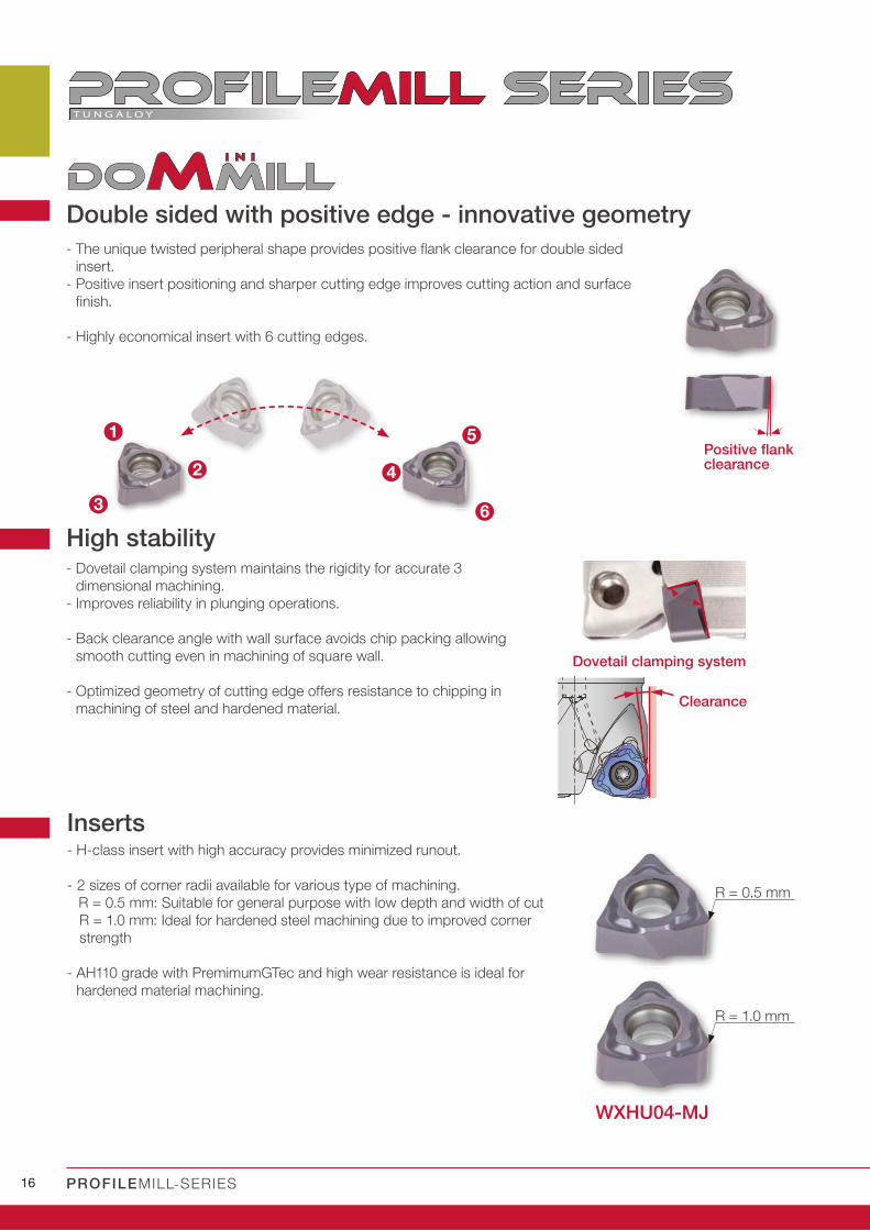
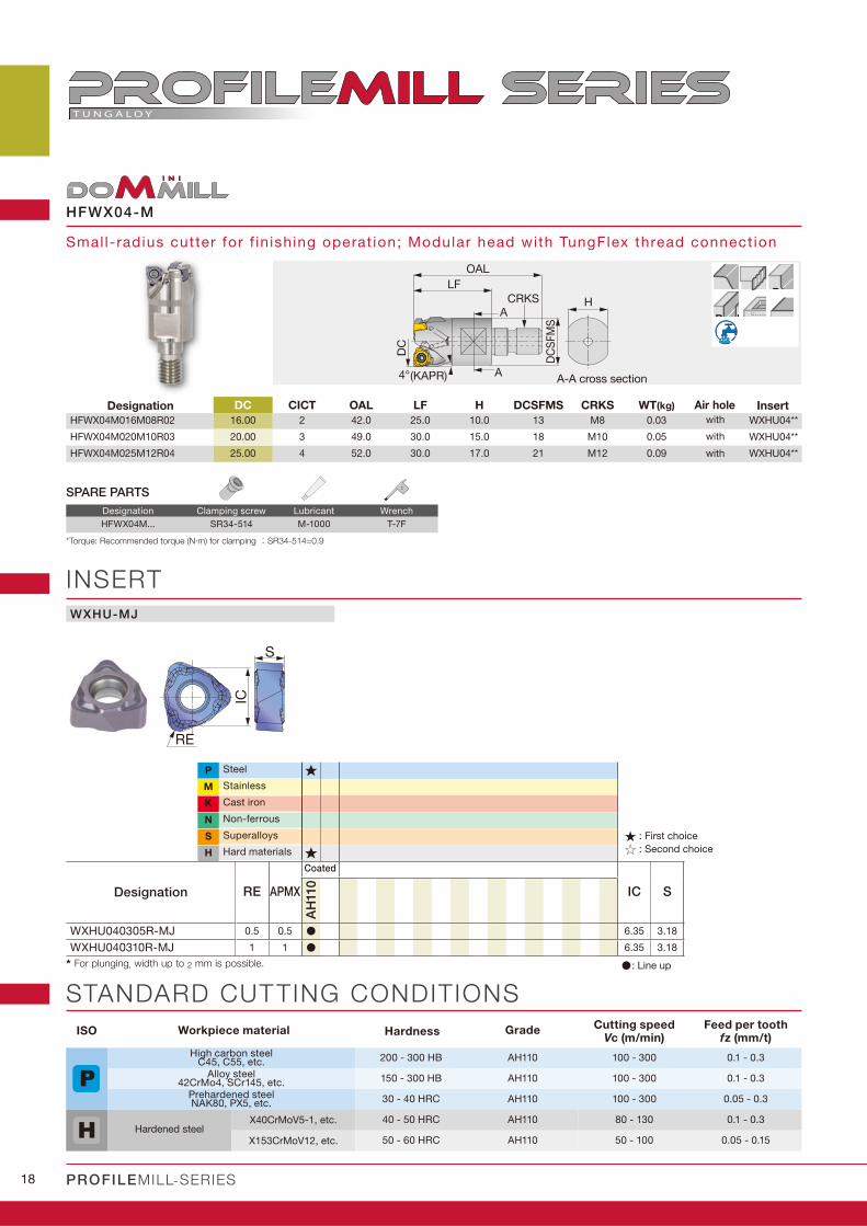
WXHU04-MJ
R = 0.5 mm
R = 1.0 mm
Double sided with positive edge - innovative geometry
- The unique twisted peripheral shape provides positive flank clearance for double sided
insert.
- Positive insert positioning and sharper cutting edge improves cutting action and surface
finish.
- Highly economical insert with 6 cutting edges.
Positive flank clearance
High stability- Dovetail clamping system maintains the rigidity for accurate 3
dimensional machining.
- Improves reliability in plunging operations.
- Back clearance angle with wall surface avoids chip packing allowing
smooth cutting even in machining of square wall.
- Optimized geometry of cutting edge offers resistance to chipping in
machining of steel and hardened material.
Dovetail clamping system
Clearance
Inserts- H-class insert with high accuracy provides minimized runout.
- 2 sizes of corner radii available for various type of machining.
R = 0.5 mm: Suitable for general purpose with low depth and width of cut
R = 1.0 mm: Ideal for hardened steel machining due to improved corner
strength
- AH110 grade with PremimumGTec and high wear resistance is ideal for
hardened material machining.
17
2.0
1.5
1.0
0.5
0
0.20
0.15
0.10
0.05
020 40 60 80
37.
5 m
m
w w w . t u n g a l o y . c o m
A CC E L E R A T E D M A C H I N I N G
Competitor ACompetitor A Competitor BCompetitor B
feedfeed
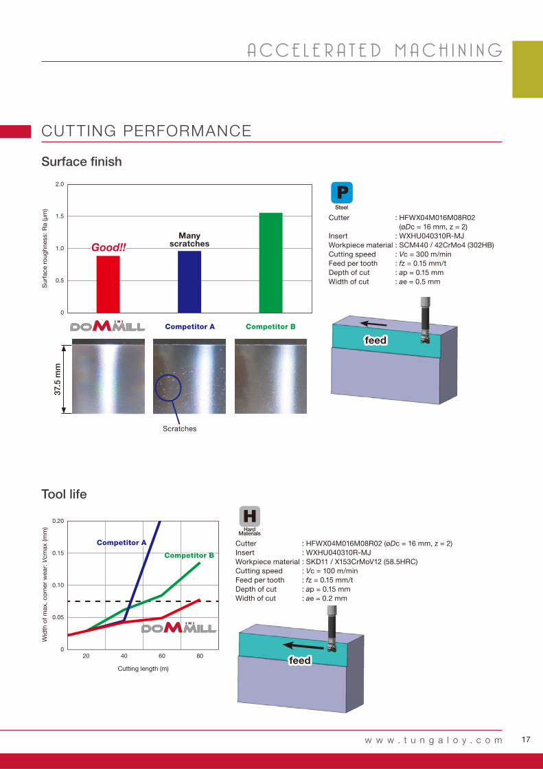
Many scratchesGood!!Good!!
feedfeed
Su
rface r
ou
gh
ness:
Ra (μ
m)
Wid
th o
f m
ax. co
rner
wear:
Vcm
ax (m
m)
Cutting length (m)
Surface finish
Tool life
CUTTING PERFORMANCE
: HFWX04M016M08R02
(øDc = 16 mm, z = 2)
: WXHU040310R-MJ
: SCM440 / 42CrMo4 (302HB)
: Vc = 300 m/min
: fz = 0.15 mm/t
: ap = 0.15 mm
: ae = 0.5 mm
: HFWX04M016M08R02 (øDc = 16 mm, z = 2)
: WXHU040310R-MJ
: SKD11 / X153CrMoV12 (58.5HRC)
: Vc = 100 m/min
: fz = 0.15 mm/t
: ap = 0.15 mm
: ae = 0.2 mm
Cutter
Insert
Workpiece material
Cutting speed
Feed per tooth
Depth of cut
Width of cut
Cutter
Insert
Workpiece material
Cutting speed
Feed per tooth
Depth of cut
Width of cut
Competitor ACompetitor A
Competitor BCompetitor B
Scratches
Steel
Hard Materials
18 PROFILEMILL-SERIES
Profilemill series
A - A 断面
DC
(KAPR)
LFOAL
DC
SFM
S
HA
A4°
CRKS R
R R
HFWX04-M
DC CICT OAL LF H DCSFMS CRKS WT(kg)
HFWX04M016M08R02 16.00 2 42.0 25.0 10.0 13 M8 0.03 WXHU04**
HFWX04M020M10R03 20.00 3 49.0 30.0 15.0 18 M10 0.05 WXHU04**
HFWX04M025M12R04 25.00 4 52.0 30.0 17.0 21 M12 0.09 WXHU04**
HFWX04M... SR34-514 M-1000 T-7F
WXHU-MJ
S
RE
IC
ISO
200 - 300 HB AH110 100 - 300 0.1 - 0.3
150 - 300 HB AH110 100 - 300 0.1 - 0.3
30 - 40 HRC AH110 100 - 300 0.05 - 0.3
40 - 50 HRC AH110 80 - 130 0.1 - 0.3
50 - 60 HRC AH110 50 - 100 0.05 - 0.15
P �M
K
N
S
H �
RE APMX IC S
AH
110
WXHU040305R-MJ 0.5 0.5 6.35 3.18
WXHU040310R-MJ 1 1 6.35 3.18
InsertDesignation Air hole
with
with
with
INSERT
STANDARD CUTTING CONDITIONS
SPARE PARTS
Designation Clamping screw Lubricant Wrench
Steel
Stainless
Cast iron
Non-ferrous
Superalloys
Hard materials
: First choice
: Second choice
: Line up* For plunging, width up to 2 mm is possible.
Coated
Designation
Cutting speedVc (m/min)
Feed per toothfz (mm/t)
Workpiece material GradeHardness
High carbon steelC45, C55, etc.
Alloy steel42CrMo4, SCr145, etc.
Prehardened steelNAK80, PX5, etc.
Hardened steelX40CrMoV5-1, etc.
X153CrMoV12, etc.
Smal l-radius cutter for f in ishing operat ion; Modular head with TungFlex thread connect ion
A-A cross section
*Torque: Recommended torque (N∙m) for clamping :SR34-514=0.9
19
CRKS
DCONMS
BHTA
LBXLF
LS
BD
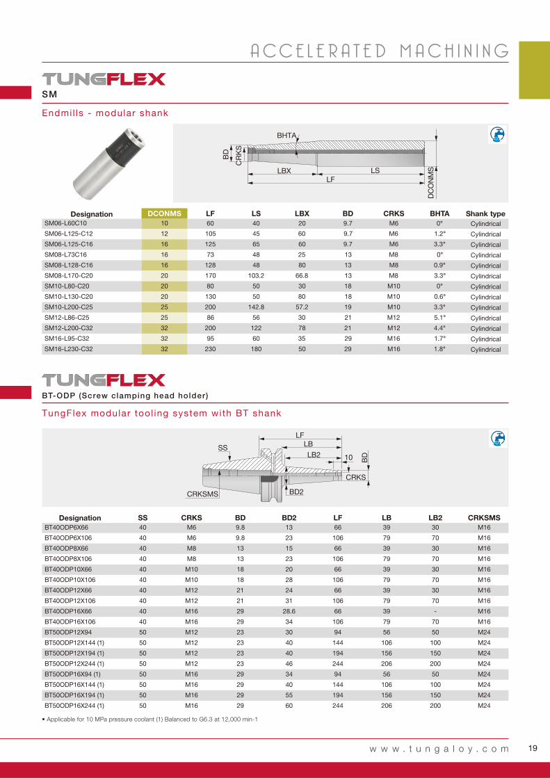
DCONMS LF LS LBX BD CRKS BHTA
SM06-L60C10 10 60 40 20 9.7 M6 0°
SM06-L125-C12 12 105 45 60 9.7 M6 1.2°
SM06-L125-C16 16 125 65 60 9.7 M6 3.3°
SM08-L73C16 16 73 48 25 13 M8 0°
SM08-L128-C16 16 128 48 80 13 M8 0.9°
SM08-L170-C20 20 170 103.2 66.8 13 M8 3.3°
SM10-L80-C20 20 80 50 30 18 M10 0°
SM10-L130-C20 20 130 50 80 18 M10 0.6°
SM10-L200-C25 25 200 142.8 57.2 19 M10 3.3°
SM12-L86-C25 25 86 56 30 21 M12 5.1°
SM12-L200-C32 32 200 122 78 21 M12 4.4°
SM16-L95-C32 32 95 60 35 29 M16 1.7°
SM16-L230-C32 32 230 180 50 29 M16 1.8°
SM
SS
BD
LF
BD2
LBLB2 10
CRKS
CRKSMS
SS CRKS BD BD 2 LF LB LB2 CRKSMS
BT40ODP6X66 40 M6 9.8 13 66 39 30 M16
BT40ODP6X106 40 M6 9.8 23 106 79 70 M16
BT40ODP8X66 40 M8 13 15 66 39 30 M16
BT40ODP8X106 40 M8 13 23 106 79 70 M16
BT40ODP10X66 40 M10 18 20 66 39 30 M16
BT40ODP10X106 40 M10 18 28 106 79 70 M16
BT40ODP12X66 40 M12 21 24 66 39 30 M16
BT40ODP12X106 40 M12 21 31 106 79 70 M16
BT40ODP16X66 40 M16 29 28.6 66 39 - M16
BT40ODP16X106 40 M16 29 34 106 79 70 M16
BT50ODP12X94 50 M12 23 30 94 56 50 M24
BT50ODP12X144 (1) 50 M12 23 40 144 106 100 M24
BT50ODP12X194 (1) 50 M12 23 40 194 156 150 M24
BT50ODP12X244 (1) 50 M12 23 46 244 206 200 M24
BT50ODP16X94 (1) 50 M16 29 34 94 56 50 M24
BT50ODP16X144 (1) 50 M16 29 40 144 106 100 M24
BT50ODP16X194 (1) 50 M16 29 55 194 156 150 M24
BT50ODP16X244 (1) 50 M16 29 60 244 206 200 M24
w w w . t u n g a l o y . c o m
A CC E L E R A T E D M A C H I N I N G
Endmil ls - modular shank
Shank type
Cylindrical
Cylindrical
Cylindrical
Cylindrical
Cylindrical
Cylindrical
Cylindrical
Cylindrical
Cylindrical
Cylindrical
Cylindrical
Cylindrical
Cylindrical
Designation
Designation
BT-ODP (Screw clamping head holder)
TungFlex modular tool ing system with BT shank
• Applicable for 10 MPa pressure coolant (1) Balanced to G6.3 at 12,000 min-1
20 PROFILEMILL-SERIES
HXN...HFWX...
9.8N
S (μm)
X..HBRM... HBFM...HBR
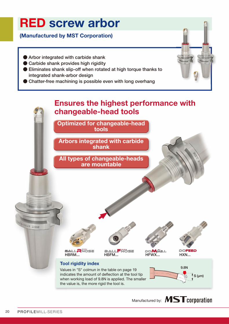
RED screw arbor
● Arbor integrated with carbide shank
● Carbide shank provides high rigidity
● Eliminates shank slip-off when rotated at high torque thanks to
integrated shank-arbor design
● Chatter-free machining is possible even with long overhang
(Manufactured by MST Corporation)
Ensures the highest performance with changeable-head tools
All types of changeable-heads are mountable
Optimized for changeable-head tools
Arbors integrated with carbide shank
Values in "S" colmun in the table on page 19
indicates the amount of defl ection at the tool tip
when working load of 9.8N is applied. The smaller
the value is, the more rigid the tool is.
Tool rigidity index
Manufactured by:

21
5LH
DCONWSG
LPRLF
BD2 BDBD3 10
LSCN
LSC
DCON
WS
G
BT40-RSG 8-130-M 50
DCONWS LSC LSCN BD LF LPR LH BD2 BD3 S WT (kg) GBT40-RSG 8-105-M 25 8.5 18 6.5 15 105 25 80 30 32 0.6 1.4 M8
BT40-RSG 8-135-M 25 8.5 18 6.5 15 135 25 110 30 32 0.7 1.8 M8
BT40-RSG 8-130-M 50 8.5 18 6.5 15 130 50 80 30 32 1.5 1.4 M8
BT40-RSG 8-160-M 50 8.5 18 6.5 15 160 50 110 30 32 1.7 1.8 M8
BT40-RSG 8-155-M 75 8.5 18 6.5 15 155 75 80 30 32 3.1 1.5 M8
BT40-RSG 8-185-M 75 8.5 18 6.5 15 185 75 110 30 32 3.4 1.9 M8
BT40-RSG 8-165-M 85 8.5 18 6.5 15 165 85 80 30 32 4 1.5 M8
BT40-RSG 10-125-M 25 10.5 22 6.5 19 125 25 100 36 38 0.4 1.8 M10
BT40-RSG 10-155-M 25 10.5 22 6.5 19 155 25 130 36 38 0.5 2.2 M10
BT40-RSG 10-150-M 50 10.5 22 6.5 19 150 50 100 36 38 0.9 1.9 M10
BT40-RSG 10-180-M 50 10.5 22 6.5 19 180 50 130 36 38 1 2.3 M10
BT40-RSG 10-175-M 75 10.5 22 6.5 19 175 75 100 36 38 1.6 2 M10
BT40-RSG 10-205-M 75 10.5 22 6.5 19 205 75 130 36 38 1.8 2.4 M10
BT40-RSG 10-200-M100 10.5 22 6.5 19 200 100 100 36 38 2.8 2 M10
BT40-RSG 10-230-M100 10.5 22 6.5 19 230 100 130 36 38 3 2.4 M10
BT40-RSG 12-125-M 25 12.5 22 6 24 125 25 100 43 45 0.3 2 M12
BT40-RSG 12-155-M 25 12.5 22 6 24 155 25 130 43 45 0.4 2.4 M12
BT40-RSG 12-150-M 50 12.5 22 6 24 150 50 100 43 45 0.5 2.1 M12
BT40-RSG 12-180-M 50 12.5 22 6 24 180 50 130 43 45 0.7 2.5 M12
BT40-RSG 12-175-M 75 12.5 22 6 24 175 75 100 43 45 0.9 2.3 M12
BT40-RSG 12-205-M 75 12.5 22 6 24 205 75 130 43 45 1.1 2.7 M12
BT40-RSG 12-200-M100 12.5 22 6 24 200 100 100 43 45 1.4 2.4 M12
BT40-RSG 12-230-M100 12.5 22 6 24 230 100 130 43 45 1.6 2.8 M12
BT50-RSG 8-120-M 25 8.5 18 6.5 15 120 25 95 30 32 0.6 4 M8
BT50-RSG 8-150-M 25 8.5 18 6.5 15 150 25 125 30 32 0.7 4.3 M8
BT50-RSG 8-145-M 50 8.5 18 6.5 15 145 50 95 30 32 1.5 4 M8
BT50-RSG 8-175-M 50 8.5 18 6.5 15 175 50 125 30 32 1.7 4.3 M8
BT50-RSG 8-170-M 75 8.5 18 6.5 15 170 75 95 30 32 3 4.1 M8
BT50-RSG 8-200-M 75 8.5 18 6.5 15 200 75 125 30 32 3.3 4.4 M8
BT50-RSG 8-180-M 85 8.5 18 6.5 15 180 85 95 30 32 3.9 4.1 M8
BT50-RSG 10-140-M 25 10.5 22 6.5 19 140 25 115 36 38 0.4 4.3 M10
BT50-RSG 10-170-M 25 10.5 22 6.5 19 170 25 145 36 38 0.5 4.6 M10
BT50-RSG 10-165-M 50 10.5 22 6.5 19 165 50 115 36 38 0.8 4.4 M10
BT50-RSG 10-195-M 50 10.5 22 6.5 19 195 50 145 36 38 0.9 4.7 M10
BT50-RSG 10-190-M 75 10.5 22 6.5 19 190 75 115 36 38 1.6 4.5 M10
BT50-RSG 10-220-M 75 10.5 22 6.5 19 220 75 145 36 38 1.7 4.8 M10
BT50-RSG 10-215-M100 10.5 22 6.5 19 215 100 115 36 38 2.7 4.5 M10
BT50-RSG 10-245-M100 10.5 22 6.5 19 245 100 145 36 38 2.9 4.8 M10
BT50-RSG 12-140-M 25 12.5 22 6 24 140 25 115 43 45 0.2 4.6 M12
BT50-RSG 12-170-M 25 12.5 22 6 24 170 25 145 43 45 0.3 5 M12
BT50-RSG 12-165-M 50 12.5 22 6 24 165 50 115 43 45 0.5 4.7 M12
BT50-RSG 12-195-M 50 12.5 22 6 24 195 50 145 43 45 0.6 5.1 M12
BT50-RSG 12-190-M 75 12.5 22 6 24 190 75 115 43 45 0.8 4.9 M12
BT50-RSG 12-220-M 75 12.5 22 6 24 220 75 145 43 45 1 5.3 M12
BT50-RSG 12-215-M100 12.5 22 6 24 215 100 115 43 45 1.3 5 M12
BT50-RSG 12-245-M100 12.5 22 6 24 245 100 145 43 45 1.5 5.4 M12
BT50-RSG 12-240-M125 12.5 22 6 24 240 125 115 43 45 2 5.2 M12
BT50-RSG 16-140-M 25 17 25 6 29 140 25 115 52 54 0.2 5.4 M16
BT50-RSG 16-165-M 50 17 25 6 29 165 50 115 52 54 0.3 5.6 M16
BT50-RSG 16-190-M 75 17 25 6 29 190 75 115 52 54 0.5 5.8 M16
BT50-RSG 16-215-M100 17 25 6 29 215 100 115 52 54 0.7 6 M16
BT50-RSG 16-240-M125 17 25 6 29 240 125 115 52 54 1.1 6.2 M16
A CC E L E R A T E D M A C H I N I N G
w w w . t u n g a l o y . c o m
Designation
TungFlex modular tool ing system with BT shank
BT-RSG (Screw clamping head holder)
S: Rigidity (μm)

22 PROFILEMILL-SERIES
Profilemill series
EBFM20S20C220 EBFM12S12S110
ZFBM200R00-MJ ZFBM120R00-MJ
AH725 AH725
350 360
0.15 0.09
0.2 0.5
0.3 1.0
8
6
4
2
0
300
200
100
0
EBRM25T32S200 EBRM20T25S160
ZRBM250-MM ZRBM200-MM
APH730 APH730
250 175
0.25 0.72
1592 4011
8 0.1 - 0.6
4 -
STAVAXSKD11 / X153CrMoV12
10705BUSCM440 / 42CrMo4
100
80
60
40
20
0
5000
4000
3000
2000
1000
0
New New
PRACTICAL EX AMPLES
Mold part
Turbine blade
Cu
ttin
g c
on
dit
ion
s
Workpiece type
Cutter
Insert
Grade
Workpiece material
Cutting speed: Vc (m/min)
Feed per tooth: fz (mm/t)
Depth of cut: ap (mm)
Pick feed: pf (mm)
Method of machining
Coolant
Machine
Results
Mold part
Mold part
Competitor
Competitor
Profiling
Dry
M/C, BT50
BallFinishNose’s tool life was 50% longer than the competitor's due to high wear resistance.
Thanks to its tough cutting edge and APH730 grade, BallRoughNose achieved 30% longer tool life compared to the competitor.
Low rigidity workpiece was limiting the competitor’s tool from increasing the feed rate. Thanks to its free cutting geometry, BallRoughNose has increased the feed rate by 40% over that of the competitor’s.
Cu
ttin
g t
ime (
h)
Profiling
Internal supply, water-soluble coolant
M/C, BT40
Competitor
BallFinishNose’s cutting length was 50% longer than the competitor’s due to excellent chip evacuation.
Cu
titn
g le
ng
th (m
)
800 m
m
1500 mm300 m
m200 mm
Cu
ttin
g c
on
dit
ion
s
Workpiece type
Cutter
Insert
Grade
Workpiece material
Cutting speed: Vc (m/min)
Feed per tooth: fz (mm/t)
Feed speed: Vf (mm/min)
Depth of cut: ap (mm)
Width of cut: ae (mm)
Method of machining
Coolant
Machine
Results
Profiling
Air
Vertical M/C
Profiling
Air blow
Specialized machine
Too
l lif
e (m
in)
Feed speed: (mm/min)
Competitor
ProductivityProductivity140%!140%!
Tool lifeTool life150%!150%!
Tool lifeTool life150%!150%!
Tool lifeTool life130%!130%!
23
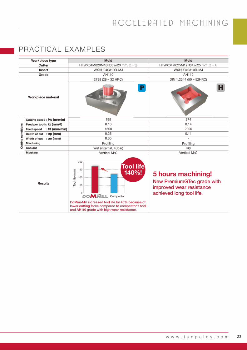
HFWX04M020M10R03 (ø20 mm, z = 3) HFWX04M025M12R04 (ø25 mm, z = 4)
WXHU040310R-MJ WXHU040310R-MJ
AH110 AH110
195 274
0.16 0.14
1500 2000
0.25 0.11
0.35 -
200
150
100
50
0
195
w w w . t u n g a l o y . c o m
A CC E L E R A T E D M A C H I N I N G
PRACTICAL EX AMPLES
2738 (28 – 32 HRC) DIN 1.2344 (50 – 52HRC)
Mold
Profiling
Wet (internal, 40bar)
Vertical M/C
Profiling
Dry
Vertical M/C
MoldWorkpiece type
Cutter
Insert
Grade
Workpiece material
Results
Cu
ttin
g c
on
dit
ion
s
Tool lifeTool life140%!140%!
Too
l lif
e (m
in)
Competitor
Cutting speed : Vc (m/min)
Feed per tooth : fz (mm/t)
Feed speed : Vf (mm/min)
Depth of cut : ap (mm)
Width of cut : ae (mm)
Machining
Coolant
Machine
DoMini-Mill increased tool life by 40% because of lower cutting force compared to competitor's tool and AH110 grade with high wear resistance.
5 hours machining!New PremiumGTec grade with improved wear resistance achieved long tool life.

Tungaloy Scandinavia ABBultgatan 38442 40 Kungälv, SwedenPhone: +46-462119200 www.tungaloy.se
Tungaloy Rus, LLC115432, Moscow, Andropov Avenue, 18, building 7, 11th fl oor (offi ce 3). Metro station “Technopark”. Business center «I-Land».Phone: +7-499-683-01-80/81 www.tungaloy.com/ru
Tungaloy Polska Sp. z o.o.ul. Genewska 24 03-963 Warszawa, PolandPhone: +48-22-617-0890 Fax: +48-22-617-0890www.tungaloy.com/pl
Tungaloy U.K. LtdThe Technology Centre, Wolverhampton Science Park Glaisher Drive, WolverhamptonWest Midlands WV10 9RU, UKPhone: +44 121 4000 231 Fax: +44 121 270 9694 www.tungaloy.com/uk [email protected]
Tungaloy Hungary KftErzsébet királyné útja 125 H-1142 Budapest, Hungary Phone: +36 1 781-6846 Fax: +36 1 781-6866www.tungaloy.com/hu [email protected]
Tungaloy TurkeyDudullu OSB 4. Cad No:4 34776 Ümraniye Istanbul, TURKEY Phone: +90 216 540 04 67 Fax: +90 216 540 04 87www.tungaloy.com.tr [email protected]
Tungaloy Benelux b.v.Tjalk 70NL-2411 NZ Bodegraven, Netherlands Phone: +31 172 630 420 Fax: +31 172 630 429www.tungaloy-benelux.com
Tungaloy CroatiaUlica bana Josipa Jelačića 87, 10430 SamoborPhone: +385 1 3326 604 Fax: +385 1 3327 683www.tungaloy.hr
Tungaloy Cutting Tool (Shanghai) Co.,Ltd.Rm No 401 No.88 Zhabei Jiangchang No.3 RdShanghai 200436, ChinaPhone: +86-21-3632-1880 Fax: +86-21-3621-1918www.tungaloy.com/cn
Tungaloy Cutting Tool (Thailand) Co.,Ltd.Interlink tower 4th Fl. 1858/5-7 Bangna-Trad Road km.5 Bangna, Bangna, Bangkok 10260ThailandPhone: +66-2-751-5711 Fax: +66-2-751-5715www.tungaloy.co.th
Tungaloy Singapore (Pte.), Ltd.62 Ubi Road 1, #06-11 Oxley BizHub 2Singapore 408734Phone: +65-6391-1833 Fax: +65-6299-4557www.tungaloy.com/sg
Tungaloy Vietnam LE 04-38, Lexington Residence 67 Mai Chi Tho, Dist. 2, Ho Chi Minh City, Vietnam Phone: +84-8-37406660 Fax: +84-8-37406662 www.tungaloy.com/sg
Tungaloy India Pvt. Ltd.Indiabulls Finance Centre,Unit # 902-A, 9th Floor,Tower 1, Senapati Bapat Marg,Elphinstone Road (West),Mumbai -400013, IndiaPhone: +91-22-6124-8804 Fax: +91-22-6124-8899www.tungaloy.com/in
Tungaloy Korea Co., Ltd#1312, Byucksan Digital Valley 5-chaBeotkkot-ro 244, Geumcheon-gu153-788 Seoul, KoreaPhone: +82-2-2621-6161 Fax: +82-2-6393-8952www.tungaloy.com/kr
Tungaloy Malaysia Sdn Bhd50 K-2, Kelana Mall, Jalan SS6/14Kelana Jaya, 47301 Petaling Jaya, Selangor Darul Ehsan MalaysiaPhone: +603-7805-3222 Fax: +603-7804-8563www.tungaloy.com/my
Tungaloy Australia Pty LtdPO Box 2232, 68/1470 Ferntree Gully Road, Knoxfi eld Victoria 3180, AustraliaPhone: +61-3-9755-8147 Fax: +61-3-9755-6070www.tungaloy.com.au
PT. Tungaloy IndonesiaKompleks Grand Wisata Block AA-10 No.3-5 Cibitung Bekasi 17510, IndonesiaPhone: +62-21-8261-5808 Fax: +62-21-8261-5809www.tungaloy.com/id
Tungaloy Corporation (Head offi ce)11-1 Yoshima-KogyodanchiIwaki-city, Fukushima, 970-1144 JapanPhone: +81-246-36-8501 Fax: +81-246-36-8542www.tungaloy.co.jp
Tungaloy America, Inc.3726 N Ventura DriveArlington Heights,IL 60004, U.S.A.Phone: +1-888-554-8394 Fax: +1-888-554-8392www.tungaloy.com/us
Tungaloy Canada 432 Elgin St. Unit 3 Brantford, Ontario N3S 7P7, Canada Phone: +1-519-758-5779 Fax: +1-519-758-5791 www.tungaloy.com/ca
Tungaloy de Mexico S.A.C Los Arellano 113, Parque Industrial Siglo XXIAguascalientes, AGS, Mexico 20290Phone: +52-449-929-5410 Fax: +52-449-929-5411www.tungaloy.com/mx
Tungaloy do Brasil Ltda.Avd. Independencia N4158 Residencial Flora13280-000 Vinhedo, São Paulo, BrasilPhone: +55-19-38262757 Fax: +55-19-38262757www.tungaloy.com/br
Tungaloy Germany GmbHAn der Alten Ziegelei 1D-40789 Monheim, GermanyPhone: +49-2173-90420-0 Fax: +49-2173-90420-19www.tungaloy.de
Tungaloy France S.A.S.ZA Courtaboeuf - Le Rio1 rue de la Terre de feuF-91952 Courtaboeuf Cedex, FrancePhone: +33-1-6486-4300 Fax: +33-1-6907-7817www.tungaloy.fr
Tungaloy Italia S.r.I.Via E. Andolfato 10I-20126 Milano, ItalyPhone: +39-02-252012-1 Fax: +39-02-252012-65www.tungaloy.it
Tungaloy Czech s.r.o.Turanka 115CZ-627 00 Brno, Czech RepublicPhone: +420-532 123 391 Fax: +420-532 123 392www.tungaloy.cz
Tungaloy Ibérica S.L.C/Miquel Servet, 43B, Nau 7 Pol. Ind. BufalventES-08243 Manresa (BCN), SpainPhone: +34 93 113 1360 Fax: +34 93 876 2798www.tungaloy.es
Distributed by:
May. 2019 (TJ)Produced from Recycled paper
AS9100 Certified780062015.11.04
ISO14001 CertifiedEC97J11231997.11.26
w w w . t u n g a l o y . c o mfollow us at:f a c e b o o k . c o m / t u n g a l o y j a p a nt w i t t e r . c o m / t u n g a l o y j a p a nwww.youtube.com/tungaloycorporation
Mcled paper Ma 2019 (TJ)Moduced from Recy
06557416