robotic microphone stand for pogo studios
TRANSCRIPT

ROBOTIC MICROPHONE STAND FOR POGO STUDIOS
By
Alejandro Gomez
Dennis Yuan
Final Report for ECE 445, Senior Design, Fall 2012
TA: Igor Fedorov
12 December 2012
Project Group No. 24

ii
Abstract
We design, construct, and demonstrate a robotic microphone stand. Stepper motors drive three
linear actuators to provide motion along the x, y, and z axis. Instructions are provided by the user over
Bluetooth by a laptop using a PuTTY terminal interface. Instructions are then relayed to the ATMega328
microcontroller and used to control the speed and direction of rotation of each motor. Bump switches
are placed at the ends of the movement range for signaling back to the microcontroller. Two voltage
regulator circuits are designed to power the motors and the microcontroller. All circuit elements are laid
out on two printed circuit boards. Testing shows that stepper motors are appropriate for this
application, and we achieve the ability to transmit instructions wirelessly over sufficient distances for its
intended purpose.

iii
Contents 1. Introduction .............................................................................................................................................. 1 2 Design ......................................................................................................................................................... 2
2.1 Structural Overview ............................................................................................................................ 2 2.2 Hardware Design Overview ................................................................................................................ 2
2.2.1 Block Diagram .............................................................................................................................. 2 2.2.2 Power Supply and Voltage Regulation ......................................................................................... 3 2.2.3 Stepper Motors and Linear Actuators.......................................................................................... 5 2.2.4 Motor Control Circuit ................................................................................................................... 6 2.2.5 Bluetooth RX ................................................................................................................................ 7 2.2.6 Bump Sensors ............................................................................................................................... 8 2.2.7 Microcontroller ............................................................................................................................ 9 2.2.8 Computer and Control Interface ................................................................................................ 10 2.2.9 PCB and Layout Considerations ................................................................................................. 10
3. Design Verification .................................................................................................................................. 12 3.1 Power Supply and Voltage Regulation .............................................................................................. 12
3.1.1 AC-DC 5V Power Supply ............................................................................................................. 12 3.1.2 5V to 3.3V Step Down Voltage Regulator .................................................................................. 12 3.1.1 5V to 12V Step Up Voltage Regulator ........................................................................................ 12
3.2 Stepper Motors, Motor Controllers, and Linear Actuators .............................................................. 13 3.2.1 Stepper Motors and Motor Controllers ..................................................................................... 13 3.2.2 Linear Actuators ......................................................................................................................... 13
3.3 Bluetooth RX ..................................................................................................................................... 13 3.4 Bump Sensors.................................................................................................................................... 14 3.5 Microcontroller ................................................................................................................................. 14 3.6 Computer and Control Interface ....................................................................................................... 14
4. Costs ........................................................................................................................................................ 15 4.1 Parts .................................................................................................................................................. 15 4.2 Labor ................................................................................................................................................. 16
5. Conclusion ............................................................................................................................................... 17 5.1 Accomplishments .............................................................................................................................. 17 5.2 Uncertainties ..................................................................................................................................... 17 5.3 Ethical Considerations ....................................................................................................................... 17 5.4 Future Work ...................................................................................................................................... 17
References .................................................................................................................................................. 18 Appendix A Requirement and Verification Table ................................................................................... 19 Appendix B Circuit Simulation ............................................................................................................... 21 Appendix C Arduino Code ..................................................................................................................... 22

1
1. Introduction Mark Rubel, a music producer at Pogo Studios located in Champaign, Illinois and Audio Director for
Eastern Illinois University’s Doudna Fine Arts Center, desired a robotic microphone stand for use in his
studio.[1] His primary motivation for requiring such stand is to find a reliable way to position a
microphone from outside the recording booth in his studio for optimal recording characteristics.
The position of the microphone relative to a speaker or performer is crucial to how the recording
ultimately sounds. Finding this optimal microphone location is difficult due to the short audio of the
average person. This makes it hard to directly compare the sounds of two relative microphone positions,
since by the time a producer walks into the booth, adjusts the microphone, and walks back out, his
memory of what the previous sound was is no longer accurate. This remote control will allow for quicker
audio feedback and proper microphone positioning. A secondary motivation Mark has is to use this
stand to attract clients and enhance the recording environment. Almost anyone can record and produce
their own music at home and upload it to YouTube for mass distribution on the internet. Professional
studios must offer services or recording environments that cannot be achieved in a home studio setting,
and such a robotic microphone stand would give Pogo studios such a service. An additional benefit of
using this stand is that it provides protection of studio personnel from potentially harmful audio
environments. Finally, similar products currently on the market are quite expensive and do not meet all
of his requirements. Mark is looking for a low cost solution.
Our design has several features that Mark is looking for. It can move two feet along both the x and y
axis, and three feet along the vertical axis. Movement can either be in preset increments or by providing
a desired location. It is wirelessly controlled, and is controlled by a laptop using open source software.
Movement is provided by three stepper motors that each drive a linear actuator. We have programmed
the ability to store up to ten microphone positions and load them at any time. These stored positions
are saved even when the system is powered down. It uses an external power source, a wall outlet,
separate from that which supplies power to the microphone.

2
Microcontroller
Power supply and
voltage regulation
Computer and
control interface
Sensors Motor control
circuit
Power
Information
Bluetooth RX
Stepper motors
and linear
actuators
2 Design
2.1 Structural Overview The stationary base of the stand is made of a single wooden board that measures 2ft. by 2ft. The first
linear actuator is mounted directly onto the wooden base along tracks for stability. We label the axis of
movement for the first linear actuator the y axis. The second linear actuator is then mounted to the first
set of tracks and provides movement along a direction perpendicular to the first actuator. We label this
second axis of movement the x axis. The third linear actuator is mounted vertically, 1 ft. above where it
is mounted, providing movement along the z axis. A rod to mount the microphone to is attached to the
third actuator.
Wires are strung from the three motors to the base of the stand for interfacing with the control
hardware. Four wires are required for each motor, two for each coil. Three wires are strung from the
bump sensors attached at the ends of the linear actuators to the base of the stand for interfacing with
the control hardware. The control hardware consists of two printed circuit boards attached to the base
of the platform. The microcontroller, Bluetooth chip, motor controller chips, and power regulators are
all distributed between these two PCBs.
2.2 Hardware Design Overview
2.2.1 Block Diagram
Figure 1 The high level block diagram of our robotic microphone stand

3
Table 1 Table of upper estimate for total power draw
Component Rated Voltage (V) Maximum Current (mA) Max Power Draw (W)
Microcontroller[2] 5 250 1.25
Motor controllers[3] 5 0.02 0.0001 (x3)
Bump sensors 5 5 0.025 (x6)
Bluetooth[4] 3.3 100 0.33
Motor[5] 2.7 2000 5.4 (x3)
Total 17.93
2.2.2 Power Supply and Voltage Regulation
The three components of the power supply and voltage regulation block are the commercial AC to DC
commercial power supply which outputs 5V DC, a step down voltage regulator to convert 5V DC to 3.3V
DC, and a step up voltage regulator to convert 5V DC to 12V DC.
2.2.2.1 AD-DC 5V Power Supply
We are using a commercial power supply to convert AC voltage to a 5V DC output. The manufacturer is
TKD-Lambda Americas, Inc. The specific model is the LS35-5, which is rated for up to 35W.[6] An upper
estimate for the power required is shown in Table 1. We purchased a power supply that can handle up
to 90 percent more power as a precaution to account for future design changes and possible
inefficiencies not taken into consideration during the initial design phase, like voltage regulator
efficiencies.
2.2.2.2 5V to 3.3V Step Down Voltage Regulator
The Bluetooth module we are using takes a 3.3V DC input, requiring us to convert the 5V DC we receive
from the commercial power supply using a voltage regulator. One possibility would be to use an
adjustable linear regulator, like the TI LM117/LM317 series, but using linear regulators create thermal
concerns. The regulation is facilitated by burning off the rest of the power as heat. Switching regulators
are more efficient, and may not require many extra components. Instead, we use the TI PL497A
Switching Voltage Regulator in a step-down configuration. The design equations, as taken from the
application information, are
( )
( )
( ) ( )
( )
(2.1) (2.2) (2.3)
(2.4)

4
( ) ( ) [
]
( )
where IPK is the peak input current, IO is the desires output current, ton is the switch-on time, Vripple(PK) is
the maximum desired ripple voltage, VI is the expected input voltage, and VO is the desired output
voltage.[7] L, CT, R1, RCK, and CO are all component values of the surrounding circuit elements as shown in
Figure 2. The Bluetooth chip has a maximum current draw of 100 mA, so we set IOmax = 100mA and IPK =
200mA in Equation (2.1). VI and VO are set to 5V and 3.3V, respectively, in Equation (2.2). We pick a
convenient L of 68µH, since Coilcraft provided inductor samples at this inductance, for a ton of 8µs. CT is
chosen to be 100pF, again a convenient value, from Equation (2.3). R1 = 2.1kΩ from Equation (2.4). RCL =
2.5Ω from Equation (2.5). CO should be at least 50µF for a maximum Vripple(PK) of 1 percent of the output
voltage. A larger CO will simply provide a smaller ripple voltage, so we are using a 100µF. We are also
using a 470µF bypass capacitor, labeled C_IN in Figure 2, at the input voltage to protect the chip from
any voltage spikes or transients.
2.2.2.3 5V to 12V Step Up Voltage Regulator
While the motors are rated for 2.7V, the motor control IC we are using requires a motor voltage of 8V-
35V for proper operation, and then uses active current limiting to make sure the current through the
stepper motors is not higher than what is rated. We are using the TI LM2585 3A Flyback Regulator in a
boost configuration, as taken from the application notes.[8] The use of a linear regulator here is not
possible, since we need to step the voltage up. While there are no design equations, TI does have the
Simple Switcher design software for picking component values. However, the level of current we want
to draw from this particular regulator is not supported by the application (the software suggests another
part for higher efficiency). Instead, we base our component values on the sample circuits in the
application notes. CIN2 = .1µF, RC = 3kΩ, and CC = .39µF. We use the same 68µH Coilcraft inductor that we
used in the step down regulator for convenience. A 1N5822 schottky diode is used since it is rated for 3A
(2.5) (2.6)
Figure 2 Schematic of step-down voltage regulator to power Bluetooth chip. Converts 5V DC to 3.3V DC.

5
and a maximum reverse voltage of 40V, both less than the 2A and 12V that it will be operating at.[9]
Capacitor COUT1 is used to store energy to be discharged when the regulator is switched off. The
capacitor must be sufficiently large, and an 1800µF is used. COUT2 is added to filter out transients and
voltage spikes to protect the motor control board that is powered by this regulator. Again a 470µF
capacitor is used for CIN to protect the chip from voltage transients. The full schematic is shown in Figure
3. There are three copies of this circuit, one for each motor. This is for added modularity, simplifying
testing, and also allows us to use a lower power regulator instead of a large regulator that must handle
up to 6A of current.
2.2.3 Stepper Motors and Linear Actuators
We are using three stepper motors to each spin a screw rod that moves a platform along the screw rod.
This use of screw rods is called a linear actuator.
2.2.3.1 Stepper Motors
We are using stepper motors to drive the linear actuators. We decided on stepper motors over other
motors for the precision that this motor type provides over other DC motors. With stepper motors, we
can dictate exactly how many steps we want the motor to rotate. The specific motor we are using is the
Pololu Stepper Motor rated for 2.7V and 1000mA.[5] Each motor contains two coils that work to spin
the motor in discrete steps. There are 200 steps per revolution, and each motor is controlled
independently of the others.
2.2.3.1 Linear Actuators
Each linear actuator is comprised of a motor attached to a screw rod with a nut that is threaded onto
the rod. The orientation of the nut is held constant so that spinning the rod moves the nut, or anything
attached to it, along the rod. Depending on the incline of the threads, a faster or slower linear speed can
be achieved given a constant motor speed. We choose a rod that moves 1in per revolution for
movement along all three axes. This scheme of movement provides with a constant linear speed,
whereas using another scheme with pivoting arms might not provide a constant relationship between
motor speed and linear speed. For each step of the motor, we can expect to move 1/200 in = 5 mils. This
is our minimal linear resolution.
Figure 3 Schematic of step-up voltage regulator to power motors. Converts 5V DC to 12V DC.

6
2.2.4 Motor Control Circuit
The microcontroller cannot directly power the motors, since the motor currents would be too much for
the microcontroller to source. Instead, we are using the Pololu Stepper Motor Driver Carrier. It uses the
Allegro A4988 stepper motor controller IC, and simplifies our control scheme. It not only translates the
control signals from the microcontroller into the appropriate high power waveforms to power the
motors, it also has active current limiting so that we can use almost any stepper motor with it. This
controller has many features, including sleep mode, reset, enable, and the ability to drive the stepper
motors microsteps as small as a sixteenth step. The motors are always enabled and are never reset or
put into sleep mode in our design.[3]
We are using the controller in full step mode, since we feel that the 5 mil resolution is more than
adequate for this application. Using the controller in this way also reduces the number of components
required, since many of the inputs are internally pulled to default values. MS1, MS2, MS3, and NOT_EN
are pulled low, meaning the motors are always enabled and are in full step mode by default. NOT_SLP is
pulled up by default, so connecting NOT_RST to it means the motors are never put to sleep or reset. No
external components are required in our schematic, as shown in Figure 4. Each of the three controllers
control one motor and is powered by a single 12V regulator.
The motors are rated for 2.7V, but this controller only takes motor voltages of 8V-35V. To make our
motor compatible, we provide a 12V input as the motor voltage and the use the active current limiting
feature on the board to keep the current below 1A per phase to not overheat the controller board and
also stay within the rated current of the motors.
The only signals we have to provide are the STEP and DIR. When a rising edge is provided to STEP, the
motor will spin one step. DIR controls whether the motor spins clockwise or counter-clockwise.
Figure 4 Schematic of Pololu Stepper Motor Drive Carrier using the Allegro A4988 stepper motor controller IC. One of three used to control the stepper motors.

7
2.2.5 Bluetooth RX
We are using Bluetooth to wirelessly control the stand. The specific profile being used is the Serial Port
Profile, which exactly simulates a serial cable between the laptop and the output of the Bluetooth
receiver.[10] The specific chip we are using is the Roving Networks RN-41 Bluetooth chip on a breakout
board provided by Sparkfun. All the specifics of the communication software stack are encapsulated
between the RN-41 and the laptop, greatly simplifying its usage. The chip requires a 3.3V input, making
necessary the 3.3V voltage regulator. Our circuit includes a reset button, an LED for pairing status, an
LED for incoming data, and a circuit to convert the 5V input the chip is receiving from the
microcontroller to 3.3V. Table 2 shows the list of IO pins, their functions, and their settings in our
implementation.[11]
The circuit to convert the 5V input to 3.3V can be seen in the schematic in Figure 5. If the incoming
signal is low, the diode will be forward biased and the voltage seen at the input of the Bluetooth RX pin
will be low. If the incoming signal is high, the diode will be reverse biased and the voltage seen will be
3.3V. Note that the RX pin of the RN-41 is connected to the TX pin, digital pin 0, of the microcontroller
and the TX pin of the RN-41 is connected to the RX pin, digital pin 1, of the microcontroller. A simulation
of this circuit is shown in Appendix B.
The actual data is received one byte at a time, with an initial start bit of 0 and then data pushed in from
lowest significant bit to highest significant bit.
Table 2 Table of RN-41 IO pin functions and settings
IO pin Functionality setting
RESET Resets chip (active low) Connected to button switch
CLK Used for SPI protocol Not used
MOSI Used for SPI protocol Not used
RTS Request to send Shorted to CTS
CTS Clear to send Shorted to RTS
CS Used for SPI protocol Not used
MISO Used for SPI protocol Not used
PIO2 Connection status (high = connected) Connected to LED
PIO3 Auto discovery = high Pulled down for no auto discovery
PIO4 Reset to factory default Pulled down for no reset capability
PIO5 Data status Not used
PIO6 Set Bluetooth master (high = auto master mode) Pulled down
PIO7 Baud rate (high = force 9600, low = 115k or firmware setting) Pulled up for baud rate of 9600
PIO10 Incorrectly labeled by Sparkfun; actually PIO9, provides extra IO pin Pulled down/not used
PIO11 Incorrectly labeled by Sparkfun; actually PIO8 provides RF data Connected to LED

8
Discuss general design alternatives. Give equations, simulations, general circuits. Describe design in
detail, addressing each major component. Include schematics with components, drawings, flowcharts,
etc. Some teams may wish to split this chapter in two: 2. Design Procedure, and 3. Design Details. This
template will not automatically update numbering systems for chapters, sections, figures, tables, etc., so
keep track of them as you develop and revise the text.
Following is a “template” for displayed math. Use the MathType extension of Word to generate your
own content, and note the use of the invisible table (no borders) to keep the optional number flush
right.
Insert math here using MathType (number)
2.2.6 Bump Sensors
We use six sensor elements for two purposes. The first is to stop the motors if the stand is pushed to the
limits of its movement range. Trying to spin the motors when the linear actuators can no longer move
could potentially damage the motors by driving them with too much current. The second is to let us
reset the microphone position counter to the correct value, since we are not using rotary encoders to
keep track of the microphone position. Each bump sensor has three connections. There is a common
lead (C), a lead that is normally open (NO) with respect to the common, and a lead that is normally
closed (NC) with respect to the common. The NO and NC leads never form a complete circuit.
Figure 5 Schematic for the Bluetooth transceiver using the Roving Networks RN-41 chip in SPP profile for wireless communication with a laptop

9
In our circuit, we connect the common leads directly as an input to the microcontroller, shown in Figure
6, labeled as BUMP_X/Y/Z_MIN/MAX. Each NO lead is grounded and each NC lead is pulled up to 5V. In
this way, the signal coming from the sensor will change from high to low whenever the level on the
sensor is pushed.
2.2.7 Microcontroller
The microcontroller interprets the instructions sent by the user and sensor information into control
signals to send to the motor controller block. It also sends data back to the user via Bluetooth. The
specific microcontroller we are using is the ATMega328, the same one that is used in the very popular
Arduino series of hobbyist microcontroller boards. It is programmed in Arduino language and has
standard libraries to support serial communication. Another added benefit is that an external
programmer is not required. We can upload sketches, Arduino code programs, to the microcontroller
through the Arduino board over USB and then pop out the microcontroller from the headers.
Reset functionality and an external oscillator are provided on the PCB for proper operation, as described
by the tutorial for building a breadboard compatible Arduino.[12] The inclusion of a 16MHz oscillator
The microcontroller is powered directly by the 5V supply, without need any further voltage regulation.
Inputs come from the bump sensors and the Bluetooth transceiver while outputs go back to the
Bluetooth transceiver and to the motor controllers.
Figure 6 Schematic for the ATMega328 microcontroller. It interfaces with the Bluetooth, sensor, and motor control blocks.
10
2.2.8 Computer and Control Interface
We are using a laptop to control the microphone stand. It is assumed the laptop has Bluetooth
capabilities, either through an integrated radio or an external dongle. The only software required is
PuTTY, an open source terminal software. Under its license, anyone is granted permission to do anything
with it and its documentation except for removing the license itself.[13]
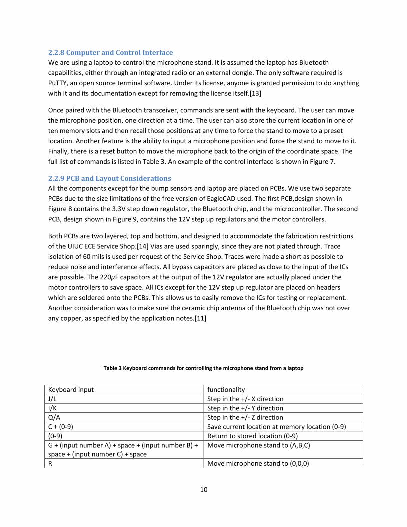
Once paired with the Bluetooth transceiver, commands are sent with the keyboard. The user can move
the microphone position, one direction at a time. The user can also store the current location in one of
ten memory slots and then recall those positions at any time to force the stand to move to a preset
location. Another feature is the ability to input a microphone position and force the stand to move to it.
Finally, there is a reset button to move the microphone back to the origin of the coordinate space. The
full list of commands is listed in Table 3. An example of the control interface is shown in Figure 7.
2.2.9 PCB and Layout Considerations
All the components except for the bump sensors and laptop are placed on PCBs. We use two separate
PCBs due to the size limitations of the free version of EagleCAD used. The first PCB,design shown in
Figure 8 contains the 3.3V step down regulator, the Bluetooth chip, and the microcontroller. The second
PCB, design shown in Figure 9, contains the 12V step up regulators and the motor controllers.
Both PCBs are two layered, top and bottom, and designed to accommodate the fabrication restrictions
of the UIUC ECE Service Shop.[14] Vias are used sparingly, since they are not plated through. Trace
isolation of 60 mils is used per request of the Service Shop. Traces were made a short as possible to
reduce noise and interference effects. All bypass capacitors are placed as close to the input of the ICs
are possible. The 220µF capacitors at the output of the 12V regulator are actually placed under the
motor controllers to save space. All ICs except for the 12V step up regulator are placed on headers
which are soldered onto the PCBs. This allows us to easily remove the ICs for testing or replacement.
Another consideration was to make sure the ceramic chip antenna of the Bluetooth chip was not over
any copper, as specified by the application notes.[11]
Table 3 Keyboard commands for controlling the microphone stand from a laptop
Keyboard input functionality
J/L Step in the +/- X direction
I/K Step in the +/- Y direction
Q/A Step in the +/- Z direction
C + (0-9) Save current location at memory location (0-9)
(0-9) Return to stored location (0-9)
G + (input number A) + space + (input number B) + space + (input number C) + space
Move microphone stand to (A,B,C)
R Move microphone stand to (0,0,0)

11
Figure 8 PCB design containing the 3.3V step down regulator, Bluetooth chip, and microcontroller
Figure 9 PCB design containing the 12V step up regulators and motor controllers.
Figure 7 Screenshot of control interface via PuTTY terminal.

12
3. Design Verification See Appendix A for full requirement and verification table.
3.1 Power Supply and Voltage Regulation Testing took place in two stages. The first stage was on a breadboard to verify out design, and the
second was on PCB.
3.1.1 AC-DC 5V Power Supply
Testing and verification consisted of measuring the 5V output on an oscilloscope. Worked as advertised.
3.1.2 5V to 3.3V Step Down Voltage Regulator
This circuit was bread-boarded as in Figure 2 with the output measured on an oscilloscope, as shown in
Figure 10. After transferring the design to PCB, however, the regulator output was around 4V. Loading
the output with the Bluetooth chip lowered the output to around 3.8V, but would periodically drop
below 3.3V. This dropping would cause the laptop to lose pairing with the Bluetooth device. We did not
have time to find the problem, but we suspect that the capacitor CT has something to do with it, as it
controls the switching frequency. The quick fix for the demonstration was to instead use the 3.3V output
from the Arduino board to power the Bluetooth chip.
3.1.1 5V to 12V Step Up Voltage Regulator
Originally this part was a 5V to 2.7V step down voltage regulator using a different chip, because we
overlooked the fact that the motor controllers could only take 8v-35V as the motor voltage. Testing with
the 2.7V regulator proved problematic in itself, because a necessary diode was not included in the
design. Loading the incorrect design would pull down the voltage of other components connected to the
5V power supply being used at the time. Adding the diode remedied this issue, but we soon realized that
we needed an entirely new regulator circuit to step the voltage up above 8V.
Testing this new regulator circuit using the LM2585-12 on a breadboard did not go smoothly at first. The
COUT1 capacitor was not large enough, less than 1000µF, and turning on the regulator resulted in the chip
Figure 10 Output of 3.3V regulator during breadboard testing Figure 11 Output of 12V regulator during breadboard testing

13
being burned out. After increasing the COUT1 to over 1000µF, the output voltage became stable, with
measured output shown in Figure 11, and the design was quickly laid out on PCB. The somewhat high
voltage transient signaled to us that the bypass capacitor might need to be increase to protect the
motor controller, causing us to increase COUT1 further to 1800µF and add an extra 220µF bypass
capacitor, COUT2 to the design.
3.2 Stepper Motors, Motor Controllers, and Linear Actuators While we had to wait until the UIUC ECE Machine Shop finished fabricating the stand and the linear
actuators, we were able to test the motors independently. A lot of the motor testing was done using the
motor controllers, since we otherwise would have had to provide two relatively high power sine waves
90 degrees out of phase with each other.
3.2.1 Stepper Motors and Motor Controllers
With the motor controllers bread-boarded, according to Figure 4, we were able to use the function
generator to spin the motors. The function generator was set to output a 5VP-P square wave with DC
offset +2.5V at 1Hz. The output of the function generator acted as the STEP input. The DIR input was
either grounded or pulled to 5V, and switched between the two to make sure the motor could be driven
both clockwise and counterclockwise.
We did have some problems causing us to burn out three motor controllers. We believe the problem
was a short circuit caused by a mistake in pulling up the SLEEP and RESET inputs in combination with
incorrectly pulling down the ENABLE input. The short caused a large current to be drawn, signaling to us
that the controller was burned out. The solution to this was to simply not externally pull up or down any
of the inputs. As previously mentioned, all of the inputs except for RESET are internally pulled up or
down. While the PCBs were designed with pull down and pull up resistors, we opted not to solder them
onto the board.
3.2.2 Linear Actuators
Testing the linear actuators was largely finding a sufficient current from the active current limiting
feature of the motor controller to spin the screw rods without risking damage to the controllers or
motors. The potentiometer on each motor controller had to be adjusted individually, since the
mechanical load on each motor is different.
3.3 Bluetooth RX The original design had the QFN version of the chip soldered to the final PCB, and the Sparkfun breakout
board used for testing purposes only. We decided to replace the QFN packaged chip directly with the
Sparkfun board after having success during the bread-boarding phase. Testing the Bluetooth chip
involved several steps. We had to figure out how to pair the device with a laptop, learn what kind of
software was required to communicate, write test code to verify operation, and then redo everything
after the circuit was placed on PCB. Testing was successful, and we were able to view the data streaming
in on an oscilloscope, with an example shown in Figure 12.

14
3.4 Bump Sensors Bump sensor testing was very simple. All that is required is an ohm meter to measure whether the
impedance between the common lead and the other two is high or low.
3.5 Microcontroller Testing the microcontroller was also very simple. Since the microcontroller is from the Arduino Uno
board, running the provided example sketches was an easy way to test the functionality of the
microcontroller. We did have an Arduino Uno board burn out for an unknown reason over the
Thanksgiving holidays, but purchased a replacement quickly to continue testing.
3.6 Computer and Control Interface Little testing was required to verify the operation of the laptop used to send instructions. Testing the
use of the PuTTY interface was required for testing the Bluetooth module, so they were basically tested
simultaneously.
“1” = x31 = 00110001 “a” = x61 = 01100001
“A” = x41 = 01000001 “!” = x21 = 00100001
Figure 12 Test data from the TX pin of the Bluetooth chip. Note that bits are received lowest significant bit first.

15
4. Costs Total cost is $17500 (labor) + $537.14 (prototype parts) = $18037.14
Total cost of production model as design is currently = $244.81
4.1 Parts Table 4 Cost of Parts
Part Manufacturer # Purchased (or acquired by other means)
# Used in final design
Retail Cost
Bulk Cost
Cost of prototype
Cost of production model
Stepper Motor Pololu 3 3 $15.95 $15.95 $47.85 $47.85
A4988 stepper motor controller Pololu 6 3 $12.95 $12.95 $77.70 $38.85
Snap-Action Switch Pololu 8 6 $0.75 $0.75 $6.00 $4.50
35W, 5V power supply TDK Lambda Americas Inc. 1 1 $19.00 $19.00 $0.00 $0.00
LM2585-12 switching regulator Texas Instruments 6 (samples) 3 $6.75 $3.51 $40.50 $10.53
LM2596 buck regulator Texas Instruments 4 0 $1.78
$7.12 $0.00
1N5819 Schottky Diode Vishay Semiconductor 2 (service shop) 1 $0.15 $0.06 $0.30 $0.06
1N5822 Schottky Diode Vishay Semiconductor 4 3 $0.46 $0.11 $1.84 $0.34
1800uF capacitor United Chemi-Con 5 3 $0.95 $0.30 $4.75 $0.90
470uF capacitor Panasonic 4 4 $0.41 $0.09 $1.64 $0.36
220uF capacitor Panasonic 4 3 $0.44 $0.10 $1.76 $0.30
100uF capacitor Panasonic 3 0 $0.33
$0.99 $0.00
150uF capacitor Panasonic 3 0 $0.51
$1.53 $0.00
TL497A regulator Texas Instruments 2 1 $2.02 $0.94 $4.04 $0.94
ATMega328 Atmel 2 1 $2.88 $1.60 $5.76 $1.60
1k surface mt resistor Panasonic 20 6 $0.10 $0.01 $2.00 $0.06
10k surface mt resistor Panasonic 22 2 $0.10 $0.01 $2.20 $0.02
1.2k surface mt resistor Panasonic 6 1 $0.10 $0.01 $0.60 $0.01
2.1k surface my resistor Panasonic 5 1 $0.10 $0.01 $0.50 $0.01
220ohm surface mt resistor Panasonic 4 2 $0.10 $0.01 $0.40 $0.02
200uH SMD inductor Signal Transformer 2 0 $1.11
$2.22 $0.00
2.5ohm resistor Bourns Inc. 2 0 $3.64
$7.28 $0.00
RN-41 on breakout Sparkfun 1 1 $59.95 $59.95 $59.95 $59.95
TO-263-5 to DIP-10 SMT adapter Proto Advantage 3 0 $4.49
$13.47 $0.00
ATMega328 with bootloader Sparkfun 2 0 $5.50
$11.00 $0.00
RN-41 QFN Sparkfun 2 0 $24.95
$49.90 $0.00
33uH inductor Coilcraft 5 (samples) 0 $1.62
$8.10 $0.00
47uH inductor Coilcraft 5 (samples) 0 $1.62
$8.10 $0.00
68uH inductor Coilcraft 5 (samples) 4 $1.62 $0.67 $8.10 $2.68
100uH inductor Coilcraft 2 (samples) 0 $1.62
$4.86 $0.00
333uH inductor Coilcraft 2 (samples) 0 $1.62
$4.86 $0.00
200ohm resistor Vishay 3 (service shop) 3 $0.23 $0.01 $0.69 $0.03

16
.1uF capacitor Vishay 3 (service shop) 3 $0.44 $0.03 $1.32 $0.09
.39uF capacitor AVC Corporation 3 (service shop) 3 $0.40 $0.40 $1.20 $1.20
2.3ohm resistor Tageo 1 (service shop) 1 $0.33 $0.04 $0.33 $0.04
22pF capacitor Vishay 2 (service shop) 2 $0.34 $0.03 $0.68 $0.06
100pF capacitor Vishay 1 (service shop) 1 $0.34 $0.03 $0.34 $0.03
white LED Everlight Electronics 8 (IEEE Lab) 2 $0.59 $0.16 $4.72 $0.32
16MHz Crystal ECS Inc 1 (service shop) 1 $0.70 $0.70 $0.70 $0.70
Sub-Mini pushbutton All Electronics Corp 2 2 $0.33 $0.18 $0.66 $0.36
Arduino Uno Arduino 1 0 $27.18
$27.18 $0.00
female headers Sparkfun 6 (IEEE lab) 2 $1.50 $1.50 $9.00 $3.00
PCB fabrication ECE service shop 3 (service shop) 2 $35.00 $35.00 $105.00 $70.00
Parts total
$537.14 $244.81
4.2 Labor Table 5 Cost of Labor
Labor wage time Total
Alejandro Gomez $35/hr 100hr $3500*2.5 = $8750
Dennis Yuan $35/hr 100hr $3500*2.5 = $8750
Labor Total $17500

17
5. Conclusion
5.1 Accomplishments Our demonstration was a great success. We were able to demo the full functionality of the project we
set out to build, and even had a bonus in the form of stepper motor music. We both feel like we learned
a lot throughout this process. At the start, neither of us were familiar with really any of the hardware
components we successfully designed. Implementing Bluetooth seemed overwhelming, learning about
using motors in practice was new, and figuring out exactly what we could do with a microcontroller
were all things that seemed daunting at first. As we read the documentation and gained more
understanding of what was actually required, we realized elements that used to seem overwhelming are
actually straight forward. We both feel much more confident jumping into a project now than when we
started the semester.
5.2 Uncertainties Since we were unable to perform testing inside Pogo Studios, the recording environment might not
support our Bluetooth implementation. While the Class 1 Bluetooth module has a large range, the actual
range is probably limited by the Bluetooth radio in the laptop. Unless the Bluetooth radio in the laptop is
also Class 1, the range will drop significantly. Soundproof walls also tend to attenuate electromagnetic
radiation as well, further degrading the signal.
5.3 Ethical Considerations to accept responsibility in making decisions consistent with the safety, health, and welfare of the public,
and to disclose promptly factors that might endanger the public or the environment;
All wireless communications devices we use in this project, the Class 1 Bluetooth module in
particular, are certified by the FCC.[11]
to seek, accept, and offer honest criticism of technical work, to acknowledge and correct errors, and to
credit properly the contributions of others;
Designs based off datasheets and application notes are properly credit. The use of PuTTY
software in our project is also ethical under the open source license that explicitly gives us permission to
use it.
5.4 Future Work Immediate work to be finished include fixing the 3.3V step down regulator circuit and getting the
JavaScript code to work over Bluetooth. Fixing the voltage regulator would eliminate the need for using
the entire Arduino board, and the microcontroller would be placed on the PCB. Getting the JavaScript
code to work would improve the look and utility of the control interface, giving it more of a “cool” factor
that Mark desires.
Other potential improvements include enclosing the hardware components in some kind of box, adding
pan or tilt capability, and writing a program to take any MIDI file and automatically play it using the
stepper motors.

18
References [1] About Pogo, Pogo Studio. [Online]. Available at:
http://www.pogostudio.net/aboutpogo.htm
[2] 8-bit AVR® Microcontroller with 4/8/16/32k Bytes In-System Programmable Flash, datasheet,
Atmel. [Online]. Available at: http://www.atmel.com/Images/doc8161.pdf
[3] A4988 DMOS Microstepping Driver with Translator and Overcurrent Protection, datasheet, Allegro
Microsystems, Inc. [Online]. Available: http://www.allegromicro.com/Products/Motor-Driver-And-
Interface-ICs/Bipolar-Stepper-Motor-Drivers/~/media/Files/Datasheets/A4988-Datasheet.ashx
[4] RN-41/RN041-N Class 1 Bluetooth Module, datasheet, Roving Networks. [Online]. Available:
http://dlnmh9ip6v2uc.cloudfront.net/datasheets/Wireless/Bluetooth/rn-41-ds-v3.3r.pdf
[5] Pololu Robotics and Electronics, Stepper Motor: Bipolar, 200 Steps/Rev, 35x36mm, 2.7V, 1000mA.
[Online]. Available: http://www.pololu.com/catalog/product/1209/specs
[6] LS Series Single Output General Purpose Power Supplies, datasheet, TDK-Lambda. [Online].
Available at: http://us.tdk-lambda.com/lp/ftp/Specs/ls.pdf
[7] TL297A 500-mA Peak Step-up, Step-down, Inverting Switching Voltage Regulator, datasheet, Texas
Instruments. [Online]. Available at: http://www.ti.com/lit/ds/symlink/tl497a.pdf
[8] LM2585 Simple Switcher® 3A Flyback Regulator, datasheet, Texas Instruments. [Online]. Available
at: http://www.ti.com/lit/ds/symlink/lm2585.pdf
[9] 1N5820-1N5822, datasheet, Fairchild Semiconductor. [Online]. Available at:
http://www.fairchildsemi.com/ds/1N/1N5822.pdf
[10] Bluetooth Special Interest Group, Serial Port Profile (SPP). [Online]. Available:
https://www.bluetooth.org/Building/HowTechnologyWorks/ProfilesAndProtocols/SPP.htm
[11] RN-41/RN041-N Class 1 Bluetooth Module, datasheet, Roving Networks. [Online]. Available at:
http://dlnmh9ip6v2uc.cloudfront.net/datasheets/Wireless/Bluetooth/rn-41-ds-v3.3r.pdf
[12] Building an Arduino on a Breadboard, Arduino. [Online]. Available at:
http://arduino.cc/en/Main/Standalone
[13] Simon Tatham, PuTTY Licence. [Online]. Last modified Jan 27, 2012. Available at:
http://www.chiark.greenend.org.uk/~sgtatham/putty/licence.html
[14] Design Requirements For Our Milled PCBs, ECE Electronics Service Shop. [Online]. Available at:
http://www.ece.illinois.edu/eshop/pcbdesign/DesignReq.htm

19
Appendix A Requirement and Verification Table Table 6 System Requirements and Verifications
Requirement Verification Verification status
(Y or N)
Power Supply and Voltage Regulation 1) Commercial power supply will deliver 5V 2) Output of switching regulator to power
Bluetooth will deliver 3.3V at up to 100mA 3) Output of individual switching regulator to
power stepper motors will deliver 12V at up to 2A
1) Hook up oscilloscope to output of the commercial supply. Plug in commercial supply to wall socket and turn on supply. a) Measure 5V output on scope.
2) Use the bench DC generator as a 5 Volt input voltage for 3.3V step down circuit. Output should be 3.3V. a) Load the 3.3V output with a 33 ohm load
and measure that the current is 100 mA b) Repeat after parts laid out on PCB
3) Use the bench DC generator as a 5 Volt input voltage for 12V step up circuit. Output should be 12 Volts a) Load the 12V output with a 1.3 ohm load
and measure that the current is 2 Amps b) Repeat for each of the three 12V regulator
circuits c) Repeat after parts laid out on PCB
Y
Y Y
Y
N Y
Y
Y
Y
Motor Controller 1) Control motor movement step by step 2) Must turn both clockwise and counter
clockwise
1) Set DIR to high. Connect output leads to oscilloscope OUT1A with OUT1B to one channel and OUT2A with OUT2B to a second channel, with B’s being grounds. Connect STEP lead to a debounced switch so that you can toggle the input to STEP. a) Toggle switch on and off manually and
observe the output on the oscilloscope to verify that each step corresponds with a rising edge. Repeat 20 times
2) Set DIR to high. Connect the output leads to an oscilloscope OUT1A with OUT1B to one channel and OUT2A with OUT2B to a second channel, with B’s being grounds. Connect the STEP lead to a function generator and send a square pulse with a frequency of 100Hz. a) Observe that the output signals are 2 square
waves with OUT2 having a 90 degree phase lag.
b) Connect DIR to ground. Observe that the output signals are 2 square waves with OUT1 having a 90 degree phase lag.
Y
Y
Y
Y
Y
Stepper Motors 1) Motor should not skip steps, should give a step
every time it’s instructed to 2) One revolution should match lead screw spec
for linear motion 3) Move both clockwise and counterclockwise
1) Set DIR to high. Run test program from microcontroller to give a square wave of period 5us with 1600 cycles as an input to the STEP pin of the motor drivers so the motor will give 200 steps. a) The motor should move one revolution.
2) Move a full revolution using test program from above a) Measure the linear distance traveled on the
lead screw with ruler. it should be 1” 3) Repeat above tests, but set DIR low for opposite
direction of rotation.
Y
Y Y
Y
Y

20
Bluetooth RX 1) Needs to establish connection with computer 2) Needs to be able to receive data to computer 3) Needs to be able to send data back to
computer 4) Data transfer should be accurate 5) Should communicate through a wall from at
least 5 meters away
1) Establish connection with computer. Connection status LED indicator should light up, showing that connection has been made
2) After establishing connection with computer, send characters in the terminal interface. Data status LED indicator should be flashing, showing that data has been received by the Bluetooth module
3) Program the microcontroller to send arbitrary location data to the computer, and echo the received data to the screen. Compare for correctness and repeat 20 times
4) See verification for Computer and Control Interface block
5) Place computer at least 5 meters away through a wall and repeat all above test procedures
Y
Y
Y
Y
Y
Computer and Control Interface 1) Send accurate serial data to the
microcontroller over Bluetooth
1) After receiving inputs keyboard, echo transmitted data on the screen before they’re sent through Bluetooth to make sure they are read correctly a) Verify data is sent by checking connection
and data status LEDs on Bluetooth RX module
b) Verify data is correctly sent by reading output of Bluetooth RX module on oscilloscope
Y
Y
Y
Sensor Elements 1) Pushing down the lever on the pumper switch
should change the output from low to high.
1) Construct the circuit as shown in the schematic and supply a voltage to the pull up resistors. The voltage should show high. a) Press and hold the lever down. The voltage
should now show low on the oscilloscope. b) Let go of the lever. The voltage should now
again read high on the oscilloscope
Y
Y
Y
Microcontroller 1) Properly send and receive signals from the
Bluetooth RX block 2) Properly send signals to motor control block 3) Properly receiving signals from sensor block
1) See verification for Computer and Control interface block
2) Place microcontroller in Arduino development board. Use LEDs to read I/O pins corresponding to motor control outputs. Run test program that sends a square wave of period 1 second to STEP output, checks for clockwise and counterclockwise operation, and phase reset functionality. a) Verify for each set of motor controls for x,y
and z axis motor control outputs 3) Connect bumpers to microcontroller and run
microcontroller test program. a) Motor control output signals should indicate
position reset when they receive a signal from their respective bumpers
Y
Y
Y
Y
Y

21
Appendix B Circuit Simulation
Figure B.1 Schematic and diode parameters of circuit to convert 5V logic input into 3.3V
Figure B.2 Simulation results of circuit to convert 5V logic input into 3.3V

22
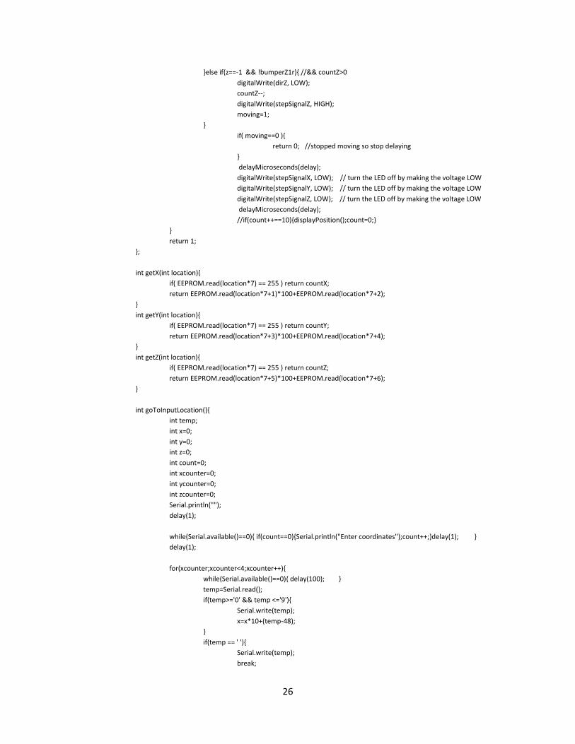
Appendix C Arduino Code

23
Code #include <EEPROM.h>
int stepSignalX = A0;//12;
int stepSignalY = A2;//11;
int stepSignalZ = A4;//10;
int dirX= A1;//9;
int dirY= A3;//8;
int dirZ= A5;//7;
int bumperX1=2;
int bumperX2=3;
int bumperY1=4;
int bumperY2=5;
int bumperZ1=6;
int bumperZ2=7;
int countX=0;
int countY=0;
int countZ=0;
int limX=4800;
int limY=4800;
int limZ=7200;
int display = 1;
int key=0;
int gdelay=2000;
int vcount=1;
void setup()
Serial.begin(9600);
pinMode(bumperX1,INPUT);
pinMode(bumperX2,INPUT);
pinMode(bumperY1,INPUT);
pinMode(bumperY2,INPUT);
pinMode(bumperZ1,INPUT);
pinMode(bumperZ2,INPUT);
pinMode(stepSignalX,OUTPUT);
pinMode(stepSignalY,OUTPUT);
pinMode(stepSignalZ,OUTPUT);
pinMode(dirX,OUTPUT);
pinMode(dirY,OUTPUT);
pinMode(dirZ,OUTPUT);
//goToOrigin();
displayPosition();
void note(int length, int note)
if (vcount==-1)vcount=1;
if (vcount==1)vcount=-1;
int delay;
int x=1;
int y=1;
int z=0;
if(note =='c') delay = 500000/130.81;
if(note =='C') delay = 500000/138.59;
if(note =='d') delay = 500000/146.83;
if(note =='D') delay = 500000/155.56;
if(note =='e') delay = 500000/164.81;
if(note =='f') delay = 500000/174.61;
if(note =='F') delay = 500000/185;
if(note =='g') delay = 500000/196;
if(note =='G') delay = 500000/207.65;

24
if(note =='a') delay = 500000/220;
if(note =='A') delay = 500000/233;
if(note =='b') delay = 500000/246;
if(note =='c'+1000) delay = 500000/261;
if(note =='C'+1000) delay = 500000/277;
if(note =='d'+1000) delay = 500000/293;
if(note =='D'+1000) delay = 500000/311;
if(note =='e'+1000) delay = 500000/329;
if(note =='f'+1000) delay = 500000/349;
if(note =='F'+1000) delay = 500000/369;
if(note =='g'+1000) delay = 500000/392;
if(note =='G'+1000) delay = 500000/415;
//if(countX+countY>0) x=-1;
//if(countX-countY>0) y=-1;
motorSteps(length,delay, 1,vcount,vcount,0);
void loop()
int steps=100;
if (Serial.available() >0)
display=1;
key=Serial.read();
if(key=='=') gdelay+=200;
if(key=='-') gdelay-=200;
int delay=gdelay;
steps=200;
if(key=='j') motorSteps(steps,delay ,1,-1, 0, 0);
if(key=='l') motorSteps(steps,delay ,1, 1, 0, 0);
if(key=='q') motorSteps(steps,delay*2,1, 0, 0, 1);
if(key=='a') motorSteps(steps,delay ,1, 0, 0,-1);
if(key=='k') motorSteps(steps,delay ,1, 0,-1, 0);
if(key=='i') motorSteps(steps,delay ,1, 0, 1, 0);
if(key=='c') storeLocation();;
if(key=='g') goToInputLocation();;
if(key>='0' && key <='9') goToLocation( getX(key),getY(key),getZ(key));
if(key=='r') goToOrigin();
//while(Serial.available()>0)Serial.read();
Serial.flush();
else
if(display)
Serial.println(gdelay);
displayPositionAndStored();
display=0;
int motorSteps( int steps, int revs, int secs , int x , int y , int z) // speed of revs/sec, fraction with revs being the
numerator and secs being the denominator
/* int loops=floor(steps/revs);

25
int rem= steps%revs;
int moving=0;
for(int i=0;i<loops;i++)
moving = step(revs,x,y,z); //200*revs
// if(moving==1) delay(5*secs); //1000*secs
moving = step(rem,x,y,z);
// if(moving==1) delay(5*secs);
//displayPosition();
*/
step(steps,revs,x,y,z);
int step( int steps , int delay, int x,int y,int z)
int count=0;
for(int i=0;i<steps;i++) // move loops*revs steps
int bumperX1r = digitalRead(bumperX1);
int bumperX2r = digitalRead(bumperX2);
int bumperY1r = digitalRead(bumperY1);
int bumperY2r = digitalRead(bumperY2);
int bumperZ1r = digitalRead(bumperZ1);
int bumperZ2r = digitalRead(bumperZ2);
if(bumperX2r && x== 1) countX = limX;
if(bumperX1r && x==-1) countX = 0;
if(bumperY2r && y== 1) countY = limY;
if(bumperY1r && y==-1) countY = 0;
if(bumperZ2r && z== 1) countZ = limZ;
if(bumperZ1r && z==-1) countZ = 0;
int moving = 0;
if(x==1 && !bumperX2r) //&& countX<limX
digitalWrite(dirX, HIGH);
countX++;
digitalWrite(stepSignalX, HIGH);
moving=1;
else if(x==-1 && !bumperX1r)//&& countX>0
digitalWrite(dirX, LOW);
countX--;
digitalWrite(stepSignalX, HIGH);
moving=1;
if(y==1 && !bumperY2r) //&& countY<limY
digitalWrite(dirY, HIGH);
countY++;
digitalWrite(stepSignalY, HIGH);
moving=1;
else if(y==-1 && !bumperY1r) //&& countY>0
digitalWrite(dirY, LOW);
countY--;
digitalWrite(stepSignalY, HIGH);
moving=1;
if(z==1 && !bumperZ2r) //&& countZ<limZ
digitalWrite(dirZ, HIGH);
countZ++;
digitalWrite(stepSignalZ, HIGH);
moving=1;
26
else if(z==-1 && !bumperZ1r) //&& countZ>0
digitalWrite(dirZ, LOW);
countZ--;
digitalWrite(stepSignalZ, HIGH);
moving=1;
if( moving==0 )
return 0; //stopped moving so stop delaying
delayMicroseconds(delay);
digitalWrite(stepSignalX, LOW); // turn the LED off by making the voltage LOW
digitalWrite(stepSignalY, LOW); // turn the LED off by making the voltage LOW
digitalWrite(stepSignalZ, LOW); // turn the LED off by making the voltage LOW
delayMicroseconds(delay);
//if(count++==10)displayPosition();count=0;
return 1;
;
int getX(int location)
if( EEPROM.read(location*7) == 255 ) return countX;
return EEPROM.read(location*7+1)*100+EEPROM.read(location*7+2);
int getY(int location)
if( EEPROM.read(location*7) == 255 ) return countY;
return EEPROM.read(location*7+3)*100+EEPROM.read(location*7+4);
int getZ(int location)
if( EEPROM.read(location*7) == 255 ) return countZ;
return EEPROM.read(location*7+5)*100+EEPROM.read(location*7+6);
int goToInputLocation()
int temp;
int x=0;
int y=0;
int z=0;
int count=0;
int xcounter=0;
int ycounter=0;
int zcounter=0;
Serial.println("");
delay(1);
while(Serial.available()==0) if(count==0)Serial.println("Enter coordinates");count++;delay(1);
delay(1);
for(xcounter;xcounter<4;xcounter++)
while(Serial.available()==0) delay(100);
temp=Serial.read();
if(temp>='0' && temp <='9')
Serial.write(temp);
x=x*10+(temp-48);
if(temp == ' ')
Serial.write(temp);
break;

27
else
xcounter--;
// if(xcounter==3) Serial.print(' ');
for(ycounter;ycounter<4;ycounter++)
while(Serial.available()==0) delay(100);
temp=Serial.read();
if(temp>='0' && temp <='9')
Serial.write(temp);
y=y*10+(temp-48);
if(temp == ' ')
Serial.write(temp);
break;
else
ycounter--;
// if(ycounter==3) Serial.print(' ');
for(zcounter;zcounter<4;zcounter++)
while(Serial.available()==0) delay(100);
temp=Serial.read();
if(temp>='0' && temp <='9')
Serial.write(temp);
z=z*10+(temp-48);
if(temp == ' ')
Serial.write(temp);
break;
else
zcounter--;
// if(zcounter==3) Serial.print(' ');
if(x>4800) x=4800;
if(y>4800) y=4800;
if(z>7200) z=7200;
Serial.println();
Serial.print("Going to ");
Serial.print(x);
Serial.print(' ');
Serial.print(y);
Serial.print(' ');
Serial.println(z);
goToLocation(x,y,z);
int goToLocation(int x,int y,int z)
int stepsX = x - countX;
int stepsY = y - countY;
int stepsZ = z - countZ;

28
int signX = stepsX > 0 ? 1 : stepsX == 0 ? 0 : -1; //m
int signY = stepsY > 0 ? 1 : stepsY == 0 ? 0 : -1;
int signZ = stepsZ > 0 ? 1 : stepsZ == 0 ? 0 : -1;
stepsX = abs(stepsX);
stepsY = abs(stepsY);
stepsZ = abs(stepsZ);
int speed=2000;
if( stepsX <= stepsY && stepsX <= stepsZ)
motorSteps( stepsX, speed, 1 , signX , signY , signZ); //m
if(stepsY <= stepsZ)
motorSteps( stepsY-stepsX, speed, 1 , 0 , signY , signZ); //m
motorSteps( stepsZ-stepsY,speed,1,0,0,signZ);
else
motorSteps( stepsZ-stepsX, speed, 1 , 0 , signY , signZ); //m
motorSteps( stepsY-stepsZ,speed,1,0,signY,0);
else if(stepsY<=stepsX && stepsY<=stepsZ)
motorSteps( stepsY, speed, 1 , signX , signY , signZ); //m
if(stepsX <= stepsZ)
motorSteps( stepsX-stepsY, speed, 1 , signX , 0, signZ); //m
motorSteps( stepsZ-stepsX,speed,1,0,0,signZ);
else
motorSteps( stepsZ-stepsY, speed, 1 , signX , 0 , signZ); //m
motorSteps( stepsX-stepsZ,speed,1,signX,0,0);
else
motorSteps( stepsZ, speed, 1 , signX , signY , signZ); //m
if(stepsY <= stepsX)
motorSteps( stepsY-stepsZ, speed, 1 , signX , signY , 0); //m
motorSteps( stepsX-stepsY,speed,1,signX,0,0);
else
motorSteps( stepsX-stepsZ, speed, 1 , signX, signY , 0); //m
motorSteps( stepsY-stepsX,speed,1,0,signY,0);
;
/*
int abs(int n)
return n<0?0-n:n;
*/
void displayPosition()
Serial.print("\n\n\n\n\n\nPosition: ");
Serial.print(countX);
Serial.print( " ");
Serial.print(countY);
Serial.print(" ");
Serial.println(countZ);

29
;
void displayPositionAndStored()
displayPosition();
for( int i='0';i<='9';i++)
if( EEPROM.read(i*7) != 255 )
Serial.print("\t\t\t\t\t\t");
Serial.print("(");
Serial.write(i);
Serial.print(")");
Serial.print("\t");
Serial.print(EEPROM.read(i*7+1)*100+EEPROM.read(i*7+2)) ;
Serial.print(" ");
Serial.print(EEPROM.read(i*7+3)*100+EEPROM.read(i*7+4)) ;
Serial.print(" ");
Serial.print(EEPROM.read(i*7+5)*100+EEPROM.read(i*7+6)) ;
Serial.println("");
;
int storeLocation()
int location;
int count=0;
Serial.println("");
delay(1);
while(Serial.available()==0) if(count==0)Serial.println("Enter a number from 0 to 9");count++;delay(1);
delay(1);
Serial.write(location=Serial.read());
if(location<'0' || location>'9') return -1;
EEPROM.write(location*7, 1);
EEPROM.write(location*7+1, floor(countX / 100) );
EEPROM.write(location*7+2, countX % 100);
EEPROM.write(location*7+3, floor(countY / 100) );
EEPROM.write(location*7+4, countY % 100);
EEPROM.write(location*7+5, floor(countZ / 100) );
EEPROM.write(location*7+6, countZ % 100);
displayPosition();
return location;
;
void goToOrigin()
countX=0;
countY=0;
countZ=0;
digitalWrite(dirX,LOW);
digitalWrite(dirY,LOW);
digitalWrite(dirZ,LOW);
if( digitalRead(bumperX1)==1 && digitalRead(bumperY1)==1 && digitalRead(bumperZ1) == 1) return;
if(digitalRead(bumperX1)==0) digitalWrite(stepSignalX,HIGH);
if(digitalRead(bumperY1)==0) digitalWrite(stepSignalY,HIGH);
if(digitalRead(bumperZ1)==0) digitalWrite(stepSignalZ,HIGH);
delay(1);

30
digitalWrite(stepSignalX,LOW);
digitalWrite(stepSignalY,LOW);
digitalWrite(stepSignalZ,LOW);
delay(1);
goToOrigin();