robotic manipulation for identi cation of flexible...
TRANSCRIPT

Robotic Manipulation for Identification ofFlexible Objects
T. M. Caldwell and D. Coleman and N. Correll?
Department of Computer Science, University of Colorado,1111 Engineering Dr, Boulder, CO 80309, USA
{caldwelt,david.t.coleman,nikolaus.correll}@colorado.edu
Abstract. This paper provides preliminary insight into stiffness profileidentification of a complex flexible object by robotic manipulation. Theobject is in the shape of the letter ‘Y’, chosen to resemble a living plant.The object is approximately modelled as a spring mass system. The robotmanipulates the object with one or two arms, grasped at the ends of the‘Y’, and makes visual measurements which locates the object’s position inspace. Identification results from an optimization approach are comparedfor both one and two arm manipulation and sensing with and withoutvision. The results are not consistent with the expected physical object’sproperties due to a failure to observe the motion dependence between theobject’s connected segments. The result provides insight into the problemof assessing the minimal information needed to identify the stiffness of aflexible object, an issue of importance to automated approaches.
1 Introduction
Physical Experiment Vision Simulation
Fig. 1. The physical experiment, vision capture (in green), and simulation of baxtermanipulating a flexible object.
? This work was supported by a NASA Early Career Faculty fellowshipNNX12AQ47GS02. We are grateful for this support.

2 Robotic Manipulation for Identification of Flexible Objects
The goal of this work is to use a robotic arm and an external vision systemto identify the behavior of the flexible object shown in Figure 1. This is animportant step toward manipulation of flexible objects such as living plants,rubber tubes, and clothes [23, 20, 2, 7].
There are many methods to model and simulate flexible objects [12, 13]. Acommon approach is to model the object as a lattice or collection of links ofmasses and springs [21, 22, 12]. This approach has been used to simulate linearobject like strings, hair, and electrical cables for which the model is a series ofmasses linked together with springs.
We also model the flexible object as a spring mass system. In [3] we mod-eled a rubber tyre in such a way, and identified the spring constants for itsuniform stiffness with a novel identification method. In this paper, we explore amore complex structure in the form of a foam ‘Y’ made of tubes with differingstiffnesses. We observe that not only must we carefully plan where to manip-ulate an object in order to sufficiently excite all of its degrees of freedom formeasurement—in this case at the end of each Y—but that this is insufficient toaccurately identify its stiffness profile, even with additional measurements madeby an external vision system. The failure in identification is due to the motiondependence between the object’s segments.
Two types of sensing are investigated. The first is the joint angles and torquesof Rethink Robotic’s Baxter robot’s arms. The second is an external vision sys-tem that produces a point cloud of the object and through filtering and fitting,can locate specific points on the object. We note that the vision cannot makeany torque or force measurements and as such can not directly measure stiffnessproperties.
We model the object with the same underlying mechanics as the robot arm—i.e., as a collection of rigid bodies connected at joints by springs—allowing us toutilize the vast theory of rigid body mechanics [16]. Also, this enables planningand control to be done in the combined arm and object configuration spaceinstead of only the end effector space or object space. We then use an optimalcontrol approach in [3] for calculating model properties that best match thebehavior of the flexible object. The physical experiment, the vision capture, andthe model can be viewed in Figure 1.
As in [3], we use variational integrators to simulate the robot and object.Variational integrators can be used to describe discrete-time equations of motionof a mechanical system. They are designed from the least action principle andhave good properties that agree with known physical phenomenon like stableenergy behavior [17]. All simulations were implemented in trep [9, 10], which isa tool to simulate articulated rigid bodies using midpoint variational integrators.
1.1 Organization of this paper
This paper is organized as follows: Section 2 sets up the experiment with therobot and flexible object. In Section 3, the flexible object is modeled as a con-nection of springs and masses. This section also reviews variational integrators.Section 4 discusses the visual perception system and the techniques to filter and

Robotic Manipulation for Identification of Flexible Objects 3
model fit the measured data. Section 5 reviews the identification algorithm from[3]. Section 6 conducts the identification on the flexible object and comparesidentification with and without vision, as well as discusses the results..
2 Example Experiment Setup
T3
T1
T2
wT2
wT1
wT3
Fig. 2. Model of Baxter manipulating a flexible object. The object is composed of 3tubes, each approximated with four rigid links. The spheres illustrate the location ofthe masses and their relative values. The tube segments are labelled T1, T2, and T3,and the points at the ends of the tube are wT1 , wT2 . and wT3 .
The goal of the example experiment is to identify stiffness properties of aflexible object. The flexible object has the shape of the letter ‘Y’. It was chosento resemble the basic geometry of a living plant. The base, or ‘trunk’ is attachedto the ground and is labelled T1. We investigate two scenarios. In the first, therobot has the point wT2 of branch T2 grasped, and the branch T3 is free (referto Figure 2). In the second scenario, the robot has both points wT2 and wT3
grasped using both arms. The goal is to manipulate the grasped branch so thatthe movement of the uncontrolled free branch can be predicted.
To improve prediction, we conduct the parameter identification optimizationalgorithm in [3] in order to identify the model’s stiffness properties. The iden-tification is made with physical contact data—i.e. joint angle and torques fromone or two arms—and a vision system to capture the motion of the full flexibleobject. The identification process is the same as in [3] once the vision data hasbeen fitted to the model.

4 Robotic Manipulation for Identification of Flexible Objects
The flexible object is foam tubing with differing widths for each of the T1,T2, and T3 sections. The three tubes are connected with a ‘Y’ PVC joint andglue. The trunk tube has length 0.813m and mass 0.064Kg. It is the widest tubewith radius 0.032m. The grasped tube has length 0.610m and mass 0.015Kg andis the second widest tube with radius 0.025m. The free tube has length 0.737mand mass 0.016Kg. It is the thinnest with radius 0.019m.
We use Rethink Robotics’ Baxter robot [5] to both manipulate and measurethe object. Baxter’s arms each have 7 degrees of freedom. The arms are designedfor compliance by means of series elastic actuators in each joint that allows forforce sensing and control. Baxter publishes the joint angles and torques at 100Hz.A picture of Baxter manipulating the flexible object is in Figure 1.
3 Model and Simulation
We model the flexible object as a spring mass system by approximating the T1,T2, and T3 segments each with four rigid links of uniform lengths and masses, con-nected by joints with torsional springs—see Figure 2. Each joint is 3-dimensionalallowing for bending and twisting motions of the flexible object. In total, theflexible object is 36 dimensional. The goal of the identification, Section 5, is toidentify the torsional springs’ spring constants. We label these parameters as ρ.
Due to Baxter’s 7 degrees of freedom arms, the system of Baxter graspingone end of the flexible object (neglecting the other arm) has a total number of43 configuration variables. When grasping both ends of the object, (using botharms) the model has a total number of 50 configuration variables. The dimen-sions, inertia, and other information concerning Baxter’s arm can be obtainedat https://github.com/RethinkRobotics.
3.1 Simulation
The model for both Baxter’s arm and the flexible object are a series of rigidlinks connected by rotational joints. As such, the dynamics of both the manipu-lator and the object can be handled together. We use variational integrators tosimulate the system dynamics. Variational integrators are a discrete-time repre-sentation of the equations of motion of a mechanical system. They are designedfrom the least action principle and have good properties that agree with knownphysical phenomenon like stable energy behavior [17].
Simulations are for a finite time interval [0, tf ] with discrete times t0, t1, . . . , tkf ,where t0 = 0, tkf = tf and kf + 1 is the total number of discrete times in theinterval. The simulation—i.e. the solving of the system dynamics—will result ina state xk := x(tk) for each k. For variational integrators, the state is composedof the configuration, labelled qk for time tk, as well as a term labelled pk, also fortime tk. For systems without external forcing, pk is the conserved momentum.For the purposes of this paper, it can simply be thought of as analogous to thediscrete velocity, which is often paired with qk to make up the state. Therefore,the state is xk := [qk, pk]T .

Robotic Manipulation for Identification of Flexible Objects 5
The literature on variational integrators [14] provides a one-step mapping toupdate the state at the previous time xk to the next time xk+1. We provide ashort high-level review of variational integrators. We write the one-step mappingwhich constitutes the systems equations of motion as
xk+1 = f(xk, ρ, tk). (1)
Here, f explicitly depends on the previous state, time, and the parameters whichwe wish to identify. For a single simulation, though, ρ remains constant. Whilewe write the equations of motion as an explicit equation, the equations are infact implicit and rely on root solving to update the state.
The equations encapsulate the system’s Lagrangian, any external forcing,holonomic constraints, as well as a choice of quadrature for approximating inte-grals. The function f can be linearized. We write
Ak =∂
∂xkf(xk, ρ, tk) and Bk =
∂
∂ρf(xk, ρ, tk). (2)
The equations to calculate the linearization with respect to the state and pa-rameters can be found in [3]. They are needed for calculating the gradient forparameter identification as part of an iterative optimization.
3.2 Simulation of Example
We use variational integrators to simulate Baxter manipulating the flexible ob-ject through the simulation tool trep [9]. The tool simulates articulated rigidbodies using midpoint variational integrators. It additionally provides partialderivative calculations that we need for the system linearization, Eq.(2).
The system of Baxter manipulating the flexible object with a single arm hasa 43 dimensional configuration. Therefore, the system’s state, xk = [qk, pk]T ,is 86 dimensional. For the system of Baxter manipulating with both arms, theconfiguration is 50 dimensional and the state is 100 dimensional. The discretedynamics f , Eq.(1), is given by the discrete system Lagrangian, discrete exter-nal forcing, and holonomoic constraints—see [3, 14]. The system Lagrangian isspecified by the kinetic and potential energies of Baxter and the object. Externalforces enter the system through the torques applied by the motors at each ofBaxter’s joints. Additionally, holonomic constraints are needed to ensure thatBaxter’s end effectors remain in contact with the object. We chose a time stepof 0.01 seconds, which matches the broadcast frequency of Baxter.
Nominally, the simulation will perfectly agree with Baxter’s measured jointtorque and angles for a given experiment. However, due to model and sensordisturbances, which are always an issue for real systems, this will not be thecase. Furthermore, since the system is unstable—i.e. small disturbances can re-sult in large changes to trajectory—directly feeding the measured torques intothe model will not result in a meaningful simulation. Therefore, the measuredjoint torques, labelled F , and measured joint angles, labelled b, must be filteredthrough a feedback loop. We use a simple proportional control law with gain K:
Fk = F k −Kk(bk − bk),
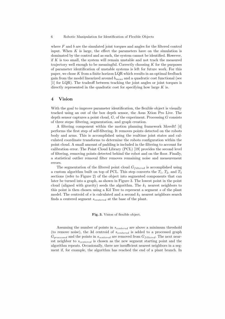
6 Robotic Manipulation for Identification of Flexible Objects
where F and b are the simulated joint torques and angles for the filtered controlinput. When K is large, the effect the parameters have on the simulation isdominated by the control and as such, the system cannot be identified. However,if K is too small, the system will remain unstable and not track the measuredtrajectory well enough to be meaningful. Correctly choosing K for the purposesof parameter identification of unstable systems is left for future work. For thispaper, we choseK from a finite horizon LQR which results in an optimal feedbackgain from the model linearized around bmeas and a quadratic cost functional (see[1] for LQR). The tradeoff between tracking the joint angles or joint torques isdirectly represented in the quadratic cost for specifying how large K is.
4 Vision
With the goal to improve parameter identification, the flexible object is visuallytracked using an out of the box depth sensor, the Asus Xtion Pro Live. Thedepth sensor captures a point cloud, G, of the experiment. Processing G consistsof three steps: filtering, segmentation, and graph creation.
A filtering component within the motion planning framework MoveIt! [4]performs the first step of self-filtering. It removes points detected on the robotsbody and arms. This is accomplished using the realtime joint states and cal-culated coordinate transforms to determine the robots configuration within thepoint cloud. A small amount of padding is included in the filtering to account forcalibration error. The Point Cloud Library (PCL) [19] provides the second levelof filtering, removing points detected behind the robot and on the floor. Finally,a statistical outlier removal filter removes remaining noise and measurementerrors.
The segmentation of the filtered point cloud Gfiltered is accomplished usinga custom algorithm built on top of PCL. This step converts the T1, T2, and T3sections (refer to Figure 2) of the object into segmented components that canlater be turned into a graph, as shown in Figure 3. The lowest point in the pointcloud (aligned with gravity) seeds the algorithm. The k1 nearest neighbors tothis point is then chosen using a Kd Tree to represent a segment s of the plantmodel. The centroid of s is calculated and a second k1 nearest neighbors searchfinds a centered segment scentered at the base of the plant.
Fig. 3. Vision of flexible object.
Assuming the number of points in scentered are above a minimum threshold(to remove noise), the 3d centroid of scentered is added to a processed graphGprocessed and the points in scentered are removed from Gfiltered. The next near-est neighbor to scentered is chosen as the new segment starting point and thealgorithm repeats. Occasionally, there are insufficient nearest neighbors in a seg-ment if, for example, the algorithm has reached the end of a plant branch. In

Robotic Manipulation for Identification of Flexible Objects 7
this case, a random point is chosen in the remaining point cloud Gfiltered tocontinue the search, until no further points remain.
The final processing step takes the disconnected points in Gprocessed and per-forms one final series of nearest neighbor searches to connect the nodes togetherto represent a flexible object modeled as a series of connected rigid bodies. Theseconnected rigid bodies give a surprisingly accurate three dimensional reconstruc-tion of a flexible object in soft-realtime, processing new point clouds at a rateaveraging 3 hz.
4.1 Fitting to Model
The processed points in Gprocessed need to be fitted to the static model of theplant to be useful. The model is a discretization of the physical object where theflexible object’s configuration specifies the location of the discretization points.Label the objects configuration as qo.
The fitting is a calculation on qo and is accomplished as follows: LetGmodel(qo)be a graph specified for configuration qo with the discrete points as its ver-tices and adjacent points in the model as its edges. Any two adjacent pointsin Gmodel(qo) can be connected by a line segment in space. Let Lmodel(qo) bethe collection of these line segments. Further, let d(p, `) be the shortest dis-tance Euclidean distance between the point p ∈ Gprocessed and line segment` ∈ Lmodel(qo). Define d(p, Lmodel(qo)) := min`∈Lmodel(qo) d(p, `) as the least dis-tance between p and any line segment in Lmodel(qo). This can be done for eachp ∈ Gprocessed. The fitting is given by the qo for which the points in Gprocessedare nearest the line segments Lmodel(qo)—i.e. by the optimization program
arg minq0
∑p∈Gprocessed
d(p, Lmodel(qo)). (3)
4.2 Vision Tracking Concerns
A number of tuned parameters make the vision filtering and fitting algorithmssensitive to object size, the distance between the camera and object, and vari-ability of the object’s thicknesses. However, it works well for our experimentalgoals.
One major shortcoming of the vision tracking pipeline developed for thisexperiment is occasional loss of data due to buffering issues and self occlusion.Because of the computational complexity of our flexible object manipulationpipeline, the experiment was run on 3 distributed commodity PCs using ROS[18]. A common issue was clock time synchronization between the three PCs,and ROS messages being dropped because of full buffers. This caused the robottransforms to be published with old time stamps and the robot self-filtering ofthe point clouds to stall, ultimately resulting in choppiness in the visual trackingof the plant model. This is an area of continued investigation and improvement.

8 Robotic Manipulation for Identification of Flexible Objects
5 Identification
The goal of the identification is to calculate the system model parameters thatbest agree with the physical behavior of the flexible object. For the example inthe paper, the parameters we wish to identify are the spring constants associatedwith the flexible object spring mass model.
Each joint of the flexible object is 3 dimensional; they all can rotate aroundeach axis. As seen in figure 4, each joint frame has the Z-axis aligned with thelink. Therefore, a bend in the tube at a joint is realized by a rotation aboutthe X- and Y -axes and a twist in the tube is a rotation about the Z-axis. Theobject’s configuration specifies the amount each frame is rotated. Because thefoam is uniformly distributed for each tube, we assume that the spring constantsassociated with bending—i.e. rotations about the X and Y axes—are the samefor a single tube.
Label the torsional spring constant about the X-axis (alternatively Y or Z)
for the ith tube as κTi,X (alt, κTi,Y or κTi,Z). There are 6 total parametersρ = [ρ1, . . . , ρ6] in our model, where
ρ1 = κT1,X = κT1,Y ,ρ2 = κT1,Z ,ρ3 = κT2,X = κT2,Y ,ρ4 = κT2,Z ,ρ5 = κT3,X = κT3,Y , andρ6 = κT3,Z .
(4)
The goal of Section 6 is to identify ρ by calculating its corresponding simula-tion that best matches measured data. This parameter optimization is presentednext.
Rotation Aboutlink i + 1
X Y
Z
link i
XY
ZX
Y
Z
Rotation
RotationX-axis Y -axis
Z-axis
About
Aboutjoint i
Fig. 4. Illustration of joint i connecting links i and i + 1 of the flexible object. Thejoint is a rotation around the X, Y , and Z axes.
Robotic Manipulation for Identification of Flexible Objects 9
5.1 Optimal Parameter Identification
The goal of parameter optimization is to calculate the model parameters ρ thatminimize a cost functional. The cost functional is the integral of a running cost`d(xk, ρ) plus a terminal cost m(xkf , ρ):
minρ
[Jd(ρ) :=
kf∑k=1
`d(xk, ρ) +md(xkf , ρ)]
constrained to the dynamics, xk+1 = f(xk, ρ, tk). Since this is a nonlinear op-timal controls problem, we turn to iterative methods like steepest descent tocalculate a local minima. In order to apply steepest descent, we must have ac-cess to the gradient of the cost, which is given in the following Lemma from[3].
Lemma 1. Suppose f(xk, ρ, tk) is C2 with respect to xk and ρ. Let Ak and Bkform the linearization of f , Eq.(2), and assume fk exists. Then,
∇Jd(ρ) =
kf∑k=1
λkBk−1 +∂
∂ρ`d(xk, ρ) +
∂
∂ρmd(xkf , ρ) (5)
where λk is the solution to the backward one-step mapping
λk = λk+1Ak +∂
∂xk`d(xk, ρ) (6)
starting from λkf = ∂∂xkf
`(xkf , ρ) + ∂∂xkf
md(xkf , ρ).
It is worth noting that fk is not guaranteed to exist, but its existence canbe checked using the Implicit Function Theorem. In [8] a couple of scenariosare shown for which such singularities occur. Also, [15] reports the gradient andHessian for optimal parameter identification in continuous time. The steepestdescent direction is −∇Jd(ρ) and the steepest descent algorithm can be applied[11].
6 Identification for Example
The parameters to be identified are the spring constants of the flexible objectgiven by the six dimensional ρ. The identification calculates the value ρ withsimulation that best matches the measured data, at least locally. We do thematching for two sets of measured data and for two scenarios—i.e. for a totalof four experiments. The first measurement set is just Baxter’s arm joint torqueand joint angle measurements while the second also includes vision (see Section4). The first scenario is Baxter manipulating one end of the object with a singlearm and the second scenario is Baxter grasping both ends using both arms.
The identification is made by minimizing the error between simulated motionfor a given ρ and measured motion at one to three points on the object, depending

10 Robotic Manipulation for Identification of Flexible Objects
on the available measurements. The three points are the points at the end ofthe three tubes, labelled wT1 , wT2 , and wT
3
(refer to Figure 2). The simulatedpoints are labelled wT1
k (ρ), wT2
k (ρ), and wT3
k (ρ) for parameters ρ at time tk. The
measured points at time tk are labelled wT1
k , wT2
k , and wT3
k . The point wT1 canonly be measured with vision, while the points wT2 and wT3 are measured bythe robotic arm when grasped, otherwise they are measured by vision.
As discussed in Section 8.1, vision measurements arrive at irregular inter-vals and sometimes of poor quality due to missing data. The following processremoves bad vision data and aligns the good data with the timing of the simu-lation: From Section 4, each frame of vision data is processed resulting in pointsGprocessed and fitted to the model with optimal fit of q?o . Recall q?o is the object’sconfiguration that best fits the data and is calculated from the program Eq.(3).The frame occurs at a time s and so we label that frame’s fit as q?o(s). Fur-thermore, the quality of the fit is quantified by the value of d(p, Lmodel(q
?o(s))),
where lesser values correspond to better fits. As such, ‘good’ data is the config-urations q?o(s) where
∑p∈Gprocessed
d(p, Lmodel(q?o(s))) < dmax, a user specified
tolerance. Data that does not meet this requirement is discarded. In order toalign the data timing with the simulation, we first interpolate in time over theremaining data using a cubic spline and label the result q?o,interp. Second, wecalculate the simulation times tk that are nearest the times s of the remainingdata. Define σ = {σ1, . . . , σkf } as σk = 1 if tk is the simulation time nearesta vision frame time s. In the identification, the cost function depends on thevision data q?o,interp(tk) for which σk = 1, where the points wTi
k , i = 1, 2, 3, arecalculated using forward kinematics.
Aside: Since we have access to q?o,interp(tk), we could alternatively choose tominimize the error in the simulated and measured configurations instead of atspecific points. However, the position of any point on the object is not uniquelyspecified by a single configuration. In fact, since the vision system cannot mea-sure a twist in a single tube, every configuration specifying the rotation aroundits local Z-axis (see Figure 4) is arbitrarily set to 0. This results in a singlemeasured object configuration, but it is unlikely that this choice results in thesame configuration as the one simulated, even if the vision perfectly measuresthe position of all locations on the object.
The identification locally minimizes a cost function Jd given by running cost`d(qk, ρ) and the terminal cost md(qkf , ρ). Both depend on the error betweensimulated and measured. Label the errors for each of the three points as:
εT1
k = (wT1
k (ρ)− wT1
k ), εT2
k := wT2
k (ρ)− wT2
k , and εT3
k = (wT3
k (ρ)− wT3
k ).
For the measurements that depend on vision, their corresponding error terms willbe multiplied by σk in the running cost. The identification then locally minimizesJd using the approach in [3] to calculate the locally optimal parameters ρ? from
Robotic Manipulation for Identification of Flexible Objects 11
an initial guess of ρ = [3, 3, 3, 3, 3, 3]T and inequality constraint ρi ≥ 0—seeSection 5.
The results follow:
6.1 Single Arm and No Vision
Without vision, the only measurements are Baxter’s arm joint torques and an-gles. Baxter is only in contact with the object at the point wT2 , and as such canonly measure the flexible object’s motion at that single point. This measurementis wT2
k . The running cost, `d, and terminal cost, md, in the cost Jd are set as:
`d(qk, ρ) =1
2(εT2
k )T εT2
k and md(qkf , ρ) =1
2(εT2
kf)T εT2
kf.
The locally optimal parameters for the single arm, no vision, case are ρ?SA,NV =
[23.780, 0.000, 18.357, 11.103, 3.200, 3.059]T .
6.2 Single Arm and Vision
With vision, the motion of each point wT1 , wT2 , and wT3 can be measured. OnlywT2
k is measured from the robot arm, while wT1
k and wT3
k are measured fromvision and are only valid at times tk where σk = 1.
The running cost is
`d(qk, ρ) =1
2σk(εT1
k )T εT1
k +1
2(εT2
k )T εT2
k +1
2σk(εT3
k )T εT3
k .
We set the running cost to be md(qkf , ρ) = `d(qkf , ρ). Executing the identifica-tion results in locally optimal parameters ρ?SA,V = [22.270, 13.593, 10.735, 8.202, 11.5111, 9.692]T
for the single arm with vision measurements scenario.
6.3 Dual Arms and No Vision
With two arms and without vision, only the points wT2 and wT3 are measured.The running and terminal costs are
`d(qk, ρ) =1
2(εT2
k )T εT2
k +1
2(εT3
k )T εT3
k
and md(qkf , ρ) = `d(qkf , ρ). The identification results in the locally optimalparameters ρ?DA,NV = [19.559, 4.965, 8.575, 10.374, 0.000, 11.287]T .
6.4 Dual Arms and Vision
Finally, with both arms and vision, all points can be measured, but only thepoints wT2 and wT3 are measured from the arm and wT3 is measured fromvision. The running and terminal costs are
`d(qk, ρ) =1
2σk(εT1
k )T εT1
k +1
2(εT2
k )T εT2
k +1
2(εT3
k )T εT3
k .
and md(qkf , ρ) = `d(qkf , ρ). The optimal parameters are identified as ρ?DA,V =
[24.840, 0.000, 12.373, 30.775, 1.406, 24.900]T .
12 Robotic Manipulation for Identification of Flexible Objects
6.5 Discussion of Results
The identified model parameters are not consistent with physical behavior. Forexample, it is unreasonable to expect that a physical tube would not have anystiffness associated with bending or twisting, which is reported by an identifiedspring constant being zero in all experiments except one. It is worth noting thateven the experiment for which the robot manipulates both ends of the objectand uses vision to locate the junction point, wT1
, results in a spring constantwith value 0.
We expect that this negative result is due to the motion dependence betweenthe object’s segments, which was not observable by the object’s motion at themeasurement locations wT1
, wT2, wT3
. In other words, we expect that with aperfect model and perfect measurements, the parameters ρ would not uniquelyspecify the motion of the measurement locations—or, at the least, that the pa-rameters are highly sensitive to disturbances. This explanation is analogous tothe obervability gramian of linear control analysis being nonsingular.
To illustrate the issue, we look at a simple two spring system. Suppose bothsprings’ spring constants differ and are unknown. One end of one spring is at-tached to one end of the other string. If the spring system is pulled apart andonly the position and forces of the free ends are measured, then the spring con-stants cannot be accurately identified, unless the attachment position is alsomeasured.
This simple two spring example and the identification results of the signifi-cantly higher dimensional system in this paper, provide insight into the problemof determining the minimal information needed to assess the stiffness of flexibleobjects. Solving such a problem would be invaluable to an automated identifi-cation routine for identification of other flexible objects with complex shapes ornonuniform stiffnesses. This problem will be addressed in future work.
Even though the identified parameters are not consistent with physical be-havior, they are still useful depending on the desired task. For instance, theidentified model is valid for the planning problem of manipulating the objectto move one a measurement point to a desired position. This problem is alsoplanned future work.
7 Conclusion
The paper investigates the problem of identifying the stiffness profile of a flexibleobject shaped like the letter ‘Y’ through robotic manipulation. The robotic armsand a vision system measure the object’s motion. Four experiments are run, onceeach for each of the following scenarios: manipulation with one or two arms andmeasurements with or without vision. The identification minimizes the errorbetween the simulated and measured movement of up to three locations onthe object depending on the available measurements. The identification resultsdo not match the objects’ expected physical properties, which we attribute toa failure to observe the motion dependence of the object’s distinct segments.

Robotic Manipulation for Identification of Flexible Objects 13
These results, while negative, provide insight into the problem of determiningthe minimal measurements needed to uniquely identify an object’s stiffness.
References
1. B. D. O. Anderson and J. B. Moore. Optimal Control: Linear Quadratic Methods.Dover Publications, INC, 1990.
2. Matthew Bell. Flexible object manipulation. PhD thesis, DARTMOUTH COL-LEGE Hanover, New Hampshire, 2010.
3. T. M. Caldwell, D. Coleman, and N. Correll. Optimal parameter identificationfor discrete mechanical systems with application to flexible object manipulation.IEEE/RSJ International Conference on Intelligent Robots and Systems, 2014.
4. D. Coleman, I. Sucan, S. Chitta, and N. Correll. Reducing the barrier to entryof complex robotic software. Journal of Software Engineering in Robotics, Specialissue on Best Practice in Robot Software Development, 2014.
5. E. Guizzo and E. Ackerman. How rethink robotics built its new baxter robotworker. IEEE Spectrum, 2011.
6. J. Hauser. A projection operator approach to the optimization of trajectory func-tionals. IFAC World Congress, 2002.
7. P Jimenez. Survey on model-based manipulation planning of deformable objects.Robotics and Computer-Integrated Manufacturing, 28(2):154–163, 2012.
8. E. Johnson, J. Schultz, and T. D. Murphey. Structured linearization of discretemechanical systems for analysis and optimal control. Transactions on AutomationScience and Engineering, 2014. (Accepted).
9. E. R. Johnson and T. D. Murphey. Scalable variational integrators for constrainedmechanical systems in generalized coordinates. IEEE Transactions on Robotics,25(6):1249–1261, 2009.
10. E. R. Johnson and T. D. Murphey. Linearizations for mechanical systems in gener-alized coordinates. In American Control Conference, pages 629–633. IEEE, 2010.
11. C. T. Kelley. Iterative Methods for Optimization. Society for Industrial and AppliedMathematics, 1999.
12. F. F. Khalil and P. Payeur. Dexterous Robotic Manipulation of Deformable Objectswith Multi-Sensory Feedback-a Review, pages 587 – 621. 2010.
13. J. Lang, D. K. Pai, and R. J. Woodham. Acquisition of elastic models for interactivesimulation. The International Journal of Robotics Research, 21(8):713–733, 2002.
14. J. E. Marsden and M. West. Discrete mechanics and variational integrators. ActaNumerica, 10(1):357–514, 2001.
15. L. M. Miller and T. D. Murphey. Simultaneous optimal estimation of mode transi-tion times and parameters applied to simple traction models. IEEE Transactionson Robotics, 29(6):1496–1503, 2013.
16. R. M. Murray, Z. Li, and S. S. Sastry. A mathematical introduction to roboticmanipulation. CRC press, 1994.
17. D. Pekarek and T. D. Murphey. A backwards error analysis approach for sim-ulation and control of nonsmooth mechanical systems. In IEEE Conference onDecision and Control and European Control Conference (CDC-ECC), pages 6942–6949, 2011.
18. Morgan Quigley, Ken Conley, Brian Gerkey, Josh Faust, Tully Foote, Jeremy Leibs,Rob Wheeler, and Andrew Y Ng. Ros: an open-source robot operating system. InICRA workshop on open source software, volume 3, 2009.

14 Robotic Manipulation for Identification of Flexible Objects
19. Radu Bogdan Rusu and Steve Cousins. 3d is here: Point cloud library (pcl). InIEEE International Conference on Robotics and Automation, pages 1–4. IEEE,2011.
20. Mitul Saha and Pekka Isto. Manipulation planning for deformable linear objects.Robotics, IEEE Transactions on, 23(6):1141–1150, 2007.
21. K. S. M. Sahari, C. H. Min, and Y. C. Hou. Dynamic modeling of string forrobotics application. In Soft Computing and Intelligent Systems (SCIS) and 13thInternational Symposium on Advanced Intelligent Systems (ISIS), pages 774–779.IEEE, 2012.
22. H. Wakamatsu and K. Takahashiand S. Hirai. Dynamic modeling of linear objectdeformation based on differential geometry coordinates. In International Confer-ence on Robotics and Automation, pages 1028–1033. IEEE, 2005.
23. Hidefumi Wakamatsu, Eiji Arai, and Shinichi Hirai. Knotting/unknotting manipu-lation of deformable linear objects. The International Journal of Robotics Research,25(4):371–395, 2006.