robotic football positioning system - ee senior designseniordesign.ee.nd.edu/2017/design...
TRANSCRIPT

Robotic
Football
Positioning
System
2017
An EE senior design project by
Eddie Hunckler Matthew King Stephen McAndrew
and Kate Sanders
Robotic Football Positioning System 1
Table of Contents
1 Introduction 2
2 Detailed System Requirements 6
3 Detailed Project Description 8
31 System Theory of Operation 8
32 System Block Diagram 11
33 Microcontroller Design and Operation 12
34 DecaWave Ranging Module Design and Operation 22
35 Wi-Fi System Design and Operation 25
36 Graphic User Interface Design and Operation 30
37 Magnetometer Design and Operation 31
38 Interfaces 35
4 System Integration Testing 36
41 Subsystem Testing 36
411 DecaWave Ranging Module 36
412 PIC32 Microcontroller 38
413 MAG3110 Magnetometer 38
414 ESP8266 Wi-Fi Module 39
415 Graphical User Interface 39
42 Requirement Comparison 39
5 User Manual Installation Manual 40
51 Installing the Robotic Football Positioning System 40
52 Setting Up the Robotic Football Positioning System 41
53 How to check that the Robotic Football Positioning System is working 41
54 How to troubleshoot the Robotic Football Positioning System 41
6 To-Market Design Changes 42
7 Conclusions 43
8 Appendix ndash Code 44
Robotic Football Positioning System 2
1 Introduction
Robotic Football is an intercollegiate engineering challenge It consists of an 8-on-8
game played by robots that are individually controlled by a unique driver The rules of this
competition are written to encourage gameplay that simulates NCAA football as closely as
possible As with any football competition one of the most important players is the one in
the quarterback position Robotic football is no exception to this assessment as a reliable
quick and accurate quarterback is necessary for playing competitively
The most difficult problem with the quarterback is completing a quick and accurate
pass to one of the wide receivers There are several elements to completing a pass that need
to be addressed in the context of robotic football The target must be selected the distance
to the target must be determined and the ball must be launched with the proper speed and
rotation to hit the target
During the past several years the emphasis of development for the Notre Dame
quarterback has shifted from primarily mechanically to primarily electrically and software
oriented The primary problem with the current setup is the quarterback cannot quickly and
accurately determine the location of the wide receivers This functionality is necessary for an
effective quarterback and essential for a winning team The current solution relies on a Pixy
CMUCam camera sensor A camera with image processing on board it allows colored objects
to be tracked This performs ideally within a small distance and in a properly lit room but in
reality the camera has to deal with non-ideal lighting longer distances and partially blocked
fields of view
Robotic Football Positioning System 3
The project goal for the Robotic Football senior design group was to design a robust
easy-to-use well-documented system that would locate and report the position of the
quarterback robot and the wide receiver robots The system would improve the current
system by extending the range and accuracy of the positioning thus increasing the
percentage of completed passes and the maximum passing distance Additionally in the
future the functionality of the board could be extended to allow the robots to move
autonomously Ideally the system would be self-contained and operate independently of the
rest of the robot This would allow the system to be developed separately and then connected
to the robots when complete Designing and implementing such a system would give the
Notre Dame Robotic Football team a distinct competitive advantage
Unlike outdoor positioning with GPS there are no standard technology systems or
protocols associated with indoor positioning Although many large companies small
businesses and hobbyists have attempted to develop indoor positioning technologies their
limited success means there are few systems currently available on the market Additionally
most of these systemsrsquo designs do not meet robotic football requirements such as accuracy
range orientation tracking ability to efficiently communicate with the robotrsquos existing
control system and low cost Taking these factors into consideration that the best course of
action was to develop an indoor positioning system from scratch something specifically
tailored to meet the needs of the robotic football team
At the heart of any positioning system is distance ranging between two objects There
are many technologies available that can accomplish this and a couple of them were initially
explored ultrasonic and Wi-Fi signal strength based methods After some experimentation
it was determined that these two approaches would not be viable Ultrasonic technology
Robotic Football Positioning System 4
depended too heavily on exact alignment of the transceivers with nothing obstructing their
way and the range was far too small The Wi-Fi based approach did not approach the
accuracy required After some more research a suitable solution was found in the DecaWave
DWM1000 radio frequency (RF) ranging module The DWM1000 is a wireless transceiver
that uses an RF communication protocol and high speed clock that allows for accurate time-
of-flight distance measurements in real time This module gives the accuracy and range
required and is relatively low cost
For this project the DWM1000 is used for ranging measurements the MAG3110
magnetometer is used for orientation measurements and the ESP8266-1 Wi-Fi is used
module for communication All three were integrated onto a custom PCB and controlled by a
PIC32 microprocessor Options for both USB power and rechargeable LiPo battery power
were added to the board to provide mobility Additionally a DIP switch package was added
to the board as it allows easy configuration to operate in the desired mode since the position
of the switches can be read as an input for the PIC32 code When used together the elements
of this custom board can create a positioning system
To do so based on the distance measurement of the DWM1000 a network of five
custom ranging boards depicted later must be created Four boards shall be placed at the
corners of the ldquofieldrdquo in which the robot is to be tracked These ranging modules serve as
beacons with known fixed locations Another ranging board shall be placed on the robot to
be tracked The board on the robot will initiate a DWM1000 ranging transaction with each of
the beacons in a set order Additionally orientation data will be continuously measured with
the magnetometer Once all the data is received it will be sent to a Message Queue Telemetry
Transport (MQTT) Wi-Fi server using the Wi-Fi module on the board A Python GUI
Robotic Football Positioning System 5
created for this project will then pull the data off the MQTT server Since the distances
between all the beacons are known the Python GUI can use trilateration to calculate the
position of the ranging board on the robot in relation to the field It will then display the
position and orientation of the robot on a screen
The system designed in this project met initial expectation and functioned as
intended It was able to track a robot on the field with an accuracy of approximately 5
inches Although it did not fulfill every proposition along its development this project did
what it was intended to do with the accuracy desired The rest of this paper will fully
describe and explain the Robotic Football senior design project This description begins with
a list of all the requirements of the overall system and each of its subsystems Following this
will be an introduction to the operating theory of the overall system as well as each of the
subsystems The interfaces used to integrate all the subsystems will then be described
Immediately after there will be a discussion of how the integrated system was tested
Knowing the success of the system a subsequent detailed user manual is included Finally
suggestions of changes and improvements to the system are made alongside conclusions
drawn from the project
Figure 1 Image of the Custom Board
Robotic Football Positioning System 6
2 Detailed System Requirements
Overall System Requirements
bull Provide accurate position information
bull Provide accurate orientation information
bull Function properly in real-world and game scenarios
bull Simple and quick to setup and configure
bull Include a GUI to visually track orientation and position
Physical Board
bull Fit easily on the robots
Microcontroller
bull Facilitate communication between the following
Ranging module
Wi-Fi communication module
Magnetometer module
Main operating system on the robot
bull Sufficient IO pins to allow for configuration switches that determine if the board is
operating as an initiator or a responder
bull Operate on a rechargeable battery or USB power
Ranging Module
bull Maximum Ranging Distance ndash the system needs to be able to measure distances at
least as long as the maximum throwing range of the quarterback 50 feet
Robotic Football Positioning System 7
bull Minimum Ranging Distance ndash the system needs to be able to measure distances down
to at most 5 feet
bull Accuracy of plusmn5 inches for distance measurements inclusively between the maximum
and minimum ranging distances
bull Communication between rangers operates in a frequency range that will not have
excessive noise or traffic interference
bull The communication protocol allows for frame filtering to distinguish between distance
measurements from different responders
bull Ranging device is compatible with the chosen microcontroller
Magnetometer
bull Provide data needed to calculate the orientation of the board
bull Account for magnetic interference from outside sources
bull Compatible with chosen microcontroller
Power
bull Ranging boards can operate on 33V supplied by USB power or supplied by
rechargeable LiPo battery
bull Ranging boards can switch between USB and LiPo rechargeable battery power
supplies
bull When battery is plugged into the board and USB power is selected rechargeable
battery must charge
bull Ranging board can operate on rechargeable LiPo battery for at least the length of one
half of a robotic football game 40 minutes
Robotic Football Positioning System 8
Wi-Fi Communication
bull Wi-Fi module is compatible with the chosen microcontroller
bull Wi-Fi communication protocol allows for easy data acquisition and manipulation
3 Detailed Project Description
31 System Theory of Operation
The most crucial aspect of the positioning system is the acquisition of accurate
distance measurements between objects These measurements are obtained by using the
DecaWave DWM1000 ranging module The DWM1000 is a wireless transceiver that operates
in the RF band It has an on-chip high-speed clock which allows it to accurately measure the
time-of-flight of a transmission between two modules The initiating module then multiplies
this time of flight by the speed of light to calculate the distance to the responding modules
This allows the robotrsquos location with respect to a second module to be tracked
Another crucial component in the positioning system is the MAG3110 magnetometer
This magnetometer reads the magnetic field strength in three directions denoted XYZ
Using this data the angle the board is pointing in relation to magnetic north can be
calculated This allows the robotrsquos orientation to be tracked
In order to collect data from the positioning system remotely an ESP8266-1 Wi-Fi
module is used This module receives the distance and orientation data from the DWM1000
and MAG3110 through the microprocessor and then sends it via Wi-Fi to an MQTT server
Robotic Football Positioning System 9
MQTT is a Wi-Fi protocol that allows users to ldquosubscribe to topicsrdquo When data is published
to a subscribed topic the data appears in that data stream
The custom PCB ranging board designed and constructed for this project contains a
DWM1000 module magnetometer ESP8266-1 Wi-Fi module a flexible USB or LiPo
battery power source an eight switch DIP (used for configuration) and their required
circuitry All of these components are connected to or controlled by a PIC32 microprocessor
To create the positioning system four of these boards are places on the robotic
football playing field (a standard basketball court approximately 94 ft x 50 ft) one at each
corner These act as responder beacons with known locations These responder beacons are
numbered and have the ability to filter messages not corresponding to their
number Another board is placed on the robot being tracked This board acts as the initiator
of ranging transactions The DWM1000 on the initiator broadcasts a message indicating that
it is starting a ranging transaction with a DWM1000 on one of the receivers At the same
time the message is sent the initiator starts a timer When the receiver gets the message
from the initiator it delays a set amount of time before sending its response back to the
initiator Once this response is received by the initiator it stops its timer Using the delay
time between sending the first message and receiving the response the DWM1000 can
extract the time of flight of the signal between the initiator and responder Multiplying by
the speed of light then gives the distance between the initiator and responder The initiator
completes one of these ranging transactions with each of the responder beacons sequentially
About 40 ranging transactions occur every second or equivalently 10 ranging transactions
are completed to each of the four beacons every second Once a transaction is complete and
the initiator calculates the distance to the beacon the information is sent through the PIC32
Robotic Football Positioning System 10
to either the robotrsquos main control board or to the ESP8266-1 Wi-Fi module where it is then
send to the MQTT server
Once the distances to each of the fixed position beacons are known trilateration can
be used to calculate the position of the robot on the playing field This entails drawing circles
around each of the beacons with their radius equal to the distance measured The intersection
of these circles gives the location of the robot To do this calculation a GUI was created in
Python This GUI grabs all the ranging data from the MQTT server via Wi-Fi calculates the
position and displays the position on the screen A diagram of the ranging systemrsquos
configuration is shown in Figure 2
Figure 2 Ranging System Configuration
This diagram shows the initiator beacon in a specific location where it ranges with the
four responder beacons The distances are calculated from the RF time-of-flight interaction
These distances are represented by the radii of the four circles surrounding the responder
beacons The point where they all intersect is the location of the initiator beacon This point
Robotic Football Positioning System 11
is calculated by the GUI by repeating a trilateration function (intersection of three circles)
for every circle combination and averaging the values
32 System Block Diagram
Figure 3 below is the block diagram for the custom ranging PCB board broken into
subsystems Also shown is the type of interface used between the subsystems The main
subsystems are the PIC32 microprocessor with configuration switches DecaWave DWM1000
ranging module ESP8266-1 Wi-Fi module MAG3110 magnetometer power supply and the
GUI The PIC32 is configured through its general inputoutput (IO) pins connected to the
configuration switches It communicates with the DWM1000 through serial SPI the
ESP8266-1 through UART and the MAG3110 through I2C The power supply provides 33
V to the board either through a USB cable or rechargeable LiPo battery The DWM1000
ranging modules communicate via RF and the ESP8266-1 and GUI communicate to the
MQTT server via Wi-Fi The PIC32 also outputs data to the robotrsquos main control board
through UART
Figure 3 Ranging System Block Diagram
Robotic Football Positioning System 12
33 Microcontroller Design and Operation
The microcontroller subsystem must minimally satisfy the following criterion It
must be able to facilitate communication between the ranging module Wi-Fi
communication module the magnetometer and the main existing microcontroller on the
robot This microcontroller must also have sufficient general purpose digital input pins to
allow for configuration switches that determine if the board is operating as a beacon or a
tracking tag Finally the microcontroller and power subsystem must be able to operate on
either a rechargeable battery or a USB power supply for stationary or mobile use
The PIC32 Microcontroller is the primary computational system in this project It
facilitates all of the data transactions between the subsystems on the board In this project
the PIC32MX795 series microcontroller is used This microcontroller has the necessary IO
and clock speeds required to implement the various systems The PIC32 is externally
programmed by a computer before operating the board The program once loaded into the
microcontroller will run when the device is turned on In its most basic setup the
PIC32MX795 microcontroller requires a minimum number of bypass capacitors and power
connections to operate These are depicted in the schematic in Figure 4 taken from the
PIC32MX5XX6XX7XX Family Data Sheet These bypass capacitors are implemented on
the bottom of the PCB due to an effort to minimize the trace length between the power pin
the capacitor and the ground plane
Robotic Football Positioning System 13
Figure 4 Recommended Minimum Connections for PIC32
In addition to these minimal connections an external 8 MHz ceramic resonator was
added to drive the clock on the PIC32MX microcontrollers as it provides a stable clock
source for the microcontrollers This external resonator is connected to pins 39 and 40 on the
PIC32MX microcontroller It is placed near the microcontroller package on the PCB to
minimize the trace length This resonator provides the external clock source for the
microcontroller and is selected as the oscillator source in the hardware configuration bits in
the PIC software This clock source is initially divided down by a factor of two The
generated number is then multiplied by a Phase-Locked Loop (PLL) to achieve a primary
oscillator speed of 80 MHz The peripheral bus clock is also configured to operate at this 80
MHz speed All the serial IO hardware is configured with the assumption that these
parameters are as stated here
Robotic Football Positioning System 14
The code is universal for the boards This means that the board can be set as either an
initiator or a responder depending on the DIP switch configuration The DIP switch is a set
of eight switches that have pull-up resistors attached These can be configured prior to
starting the board If the state of these switches has changed the microcontroller must be
reset to implement the changes The main function for the PIC32 is outlined below
Figure 5 Beginning Code Flowchart
The microcontroller starts by initializing the serial ports and the MAG3110 chip The
PIC then obtains the data from the configuration switches to determine if the board is going
to act as an initiator or a responder (switch 1) what number the board is (switches 2 and 3)
and whether the board will send data through a Wi-Fi connection (switch 8) If switch 1 is off
(0) then initiator mode has been selected and the PIC32 will run as an initiator with only
switch 8 as a function input If switch 1 is on (1) then the PIC32 will run as a responder with
switch 8 and its number as a function input Its number is taken from a parameterization
function that inputs switches 1 2 and 3 to determine if the board is a responder whether
Robotic Football Positioning System 15
itrsquos responder 1 2 3 or 4 This is based on a single addition to the binary representation of
switches 2 and 3 (00 = 1 01 = 2 10 = 3 11 = 4) Once the inputs are gathered and the PIC
enters the if-statement to determine whether the board is in initiator mode the code breaks
into two functions
Figure 6 Initiator Code Flowchart
Robotic Football Positioning System 16
If DIP switch 1 is on then the microcontroller runs the initiator() function This
program starts by defining all the messages that are used in the ranging process There is a
polling message which is sent to the responder and a response message which the board
expects to receive from the responder The function then defines all the configurations and
variables (whether numbers characters or arrays) required for the code as well as the static
functions called resp_msg_get_ts get_distanceX find_average send_wifi_data and
send_serial_data The initiator() function starts with an initialization of the DW1000 chip
peripherals followed closely by resetting and initializing the chip This is to clear any
unwanted data and reset the high-speed clock The SPI rate is set low to initialize the chip
but reset high immediately after a successful initialization If an error occurs during
initialization the function immediately ends and the SPI rate remains low Once the SPI
rate is set high the module is configured and antenna delays (for reception and transmission)
as well as response delay and timeout are set The function then enters a never-ending while
loop In this loop the get_distanceX() functions are called Their order is 1 2 3 and 4 for
simplicityrsquos sake and their number corresponds to the responder that function communicates
with After there are four if-statements that take the output from one get_distanceX()
function and shifts the corresponding array one spot to the left (deleting the leftmost value)
to open a spot for the new value In this case the function and array have the same number
(ie get_distance2() rarr avg_distance2[ ]) because they work with data from the same
responder After the arrays are altered and if Wi-Fi is enabled through DIP switch 8 the
data from the get_distanceX() functions is sent to the send_wifi_data() transmission
function This function as one would expect takes its input and sends it to the MQTT server
via Wi-Fi through UART3 The data from the MAG3110 is also measured and sent to the
Robotic Football Positioning System 17
MQTT if Wi-Fi is enabled If Wi-Fi is not enabled the initiator() function skips to the
send_serial_data() function which inputs the arrays from earlier and if it gets a serial
command (from the robot) sends the data across UART1 If not the function ends and the
initiator() function after a set delay restarts the while loop
As indicated above the get_distanceX() functions are the most important part of the
initiator() function They run the transmission and reception code that communicates
messages with the responders as described in Section 34 After getting a response the
function calculates the time-of-flight for the message and uses that to calculate the distance
to the responder If this distance is greater than zero a corresponding variable is set to that
distance and the fail_count variable (number of times the transmission has failed) is set to
zero If this fails then the fail_count variable is incremented by one and once it reaches a
specific number the distance is set to zero to indicate failure The distance whether zero or
not is returned to the initiator() function
Robotic Football Positioning System 18
Figure 7 Responder Code
If DIP switch 1 is off then the microcontroller runs the responder() function This
function requires that its parameters be defined and sent as an input Like the initiator()
function the responder() function begins starts by defining all the messages that are used in
the ranging process There is a polling message which is received by the responder and a
response message which the board sends to the initiator The function then defines all the
configurations and variables (whether numbers characters or arrays) required for the code
as well as the static functions called get_rx_timestamp resp_msg_set_ts get_distanceX
and send_wifi_ack The responder() function starts with an initialization of the DW1000 chip
peripherals followed closely by resetting and initializing the chip This is to clear any
Robotic Football Positioning System 19
unwanted data and reset the high-speed clock The SPI rate is set low to initialize the chip
but reset high immediately after a successful initialization If an error occurs during
initialization the function immediately ends and the SPI rate remains low Once the SPI
rate is set high the module is configured and antenna delays (for reception and transmission)
are set The short address is set in a switch case dependent on the responderrsquos number so that
only the responder called sends a message back to the initiator The function then enters a
never-ending while loop The loop first checks to see if it has run 100 times If so it calls the
function send_wifi_ack() which takes the responderrsquos number and sends a message through
UART3 to the MQTT saying that it is still working With this complete the responder()
function continues to a switch case where its number determines which get_distanceX()
function is run (ie case 3 rarr get_distance3()) This function runs the transmission and
reception code that communicates messages with the initiator as described in Section 34
Once done the responder() function reaches the end of the while loop and so loops
A sufficient power supply and regulation system is necessary to drive the PIC32 and
other components on the board The power system on the boards consists of several
components that allow it to operate while connected to an external power supply as well as
while connected to a LiPo battery These two modes enable several features on these
boards First the boards may be directly powered via USB while the devices are being tested
or while they are operating as beacons in their responder mode The second mode is if the
board is powered by a LiPo battery This scheme enables the board to be powered while in a
mobile configuration for instance if it is installed on a robot The final power scheme
Robotic Football Positioning System 20
utilizes both the LiPo battery and the USB power supply In this configuration the
depleted battery is charged and the USB supplies power to both the board and LiPo
charging circuits
Figure 8 Voltage Regulator Schematic
The first power system is implemented simply by using a Mini USB type B cable to
power the board The power on this input is fed into the voltage regulator circuit as well as
the power supply circuit In detail the voltage regulator circuit is built around a TPS61200
chip The desired power supply voltage for this circuit is 33v This chip is capable of
supplying 300mA at 33v Several advantages of this chip include the seamless transition
between boosting up an input voltage lower than 33v while also down-converting an input
voltage higher than 33v This enables the voltage regulator to be powered by a either a USB
power supply at 5v or a depleted battery at down to 24v The schematic that drives this
ability can be seen in Figure 8 The resistors R17 and R16 set the input voltage where this
device stops outputting This schematic was implemented as seen in Figure 9 which is an
image of the board layout that implemented this chip
Robotic Football Positioning System 21
Figure 9 Voltage Regulator Board Placement
The other feature of the power supply was the LiPo battery charging circuit which
was implemented using a MCP73831 fully integrated LiPo charge management
controller The theory of operation for this device is to provide a constant current to the
battery under charge until the device reaches a certain point and then the device goes into a
constant voltage regime until the battery is fully charged At this point the device enters a
standby mode This MCP73831 device has a resistor-programmable constant charge
current This can be seen in Figure 10 where a 2 kΩ resistor is placed between PROG pin 5
and the ground rail This is calculated with the function I_prog = 1000 V R_prog
Figure 10 LiPo Battery Charger Schematic
Robotic Football Positioning System 22
The MCP73831 chip also features a charging status indicator on pin 1 This status pin
is connected to the yellow LED on the final board seen in Figure 11 where the LED turns on
to indicate that the battery is being charged The LED turns off when the battery is fully
charged in standby mode or when the MCP73831 device is not being powered The second
case where the LED is not powered is when the board is being powered by the LiPo battery
but not being charged by the USB power input
Figure 11 LiPo Batter Charger Board Placement
34 DecaWave Ranging Module Design and Operation
The ranging system must minimally satisfy the following criterion The system needs
to be able to measure distances at least as long as the maximum throwing range of the
robotic quarterback which is less than 50 feet The system needs to also be able to accurately
measure distances down to at least 5 feet The system must have an accuracy within plusmn5
inches for distance measurements inclusively between the maximum and minimum ranging
distance The system must also operate in a frequency range that will not have excessive
noise or traffic interference The communication protocol must allow for frame filtering to
distinguish between different distance measurements This device must be able to be
integrated with the selected microcontroller
The DecaWave DWM1000 module is the most crucial part of this project The module
comes with an RF antenna and circuitry and the DWM1000 chip which contains its own
Robotic Football Positioning System 23
high-speed internal clock This device can be operated to perform two-way ranging between
a pair of DecaWave modules According to its datasheet this module is compliant with the
IEEE 802154-2011 UWB standard It supports 4 distinct bands in the 35 to 65 GHz
range It also features an SPI interface to a host microcontroller
Figure 12 DWM1000 Ranging Module Schematic
Due to the fact that the DWM1000 module is an entirely self-contained device the
necessary connections needed to operate the module are minimal The first connections are
the power and ground connections with the positive supply on pins 5 6 and 7 and the
ground supply connected to pins 8 16 21 23 and 24 as seen in Figure 12 The DWM1000
operates on a 33 V supply with 33 V logic levels as well The SPI interface pins on the
DWM1000 module are directly connected to the corresponding SPI pins on the PIC32 These
are pins CLK MISO MOSI and CS The RESET pin on the DWM1000 module is connected
to one of the general purpose IO pins on the PIC32 device The operation of this pin is as
follows Generally the state of the pin is in the high impedance mode When a reset of the
device is desired the pinrsquos output is brought low for 2 milliseconds and then the pin is
returned to the high-impedance tri-state mode This effectively resets the DWM1000
module EXTON IRQ and WAKE pins are utilized in low-power operation modes In this
Robotic Football Positioning System 24
setup they were connected to pins on the PIC32 but they were never utilized because there
was no need to implement the low-power features on the DWM1000 module
Figure 13 DWM1000 Ranging Module Board Placement
An image of the DWM1000 modulersquos placement on the PCB can be seen in Figure
13 The most significant thing to note about this is the placement of the antenna It is
important to not run a ground plane underneath the antenna on this module in order to
achieve the specified performance To ensure this the antenna portion of this board is placed
over the edge of the PCB The SPI interface to this device was facilitated by the provided
API for the DecaWave chip This API handled all of the high-level data going to and from
the device The SPI interface was setup to operate in SPI mode 0 on both the PIC32 side and
on the DecaWave side All of the SPI data was transferred from most significant bit (MSB)
to least significant bit (LSB)
The high level understanding of the DecaWave ranging transactions is detailed in the
following steps There exist two DecaWave devices one initiator and one responder The
initiator begins the transaction by sending a message with the responderrsquos unique PAN ID
and short address It simultaneously records a timestamp of the original transmission
time The responder runs a frame filter for these two identifiers in the messages it receives
Robotic Football Positioning System 25
and only proceeds with messages that have both attributes The responder reads the
timestamp of the received message and schedules a response transmission at a future time
with a previously coded delay This response message is then transmitted from the responder
back to the initiator When the message arrives the initiator takes a timestamp of the
incoming message It compares the message with the expected message to confirm the
transaction was successful If the messages do not match it throws out the reception
timestamp but if they do the initiator uses the reception timestamp to calculate the
distance between it and the responder To calculate the distance the initiator
microcontroller subtracts the original transmission timestamp and the delay time from the
received transmission timestamp This results in the time-of-flight of the transmission This
time-of-flight times the speed of light achieves the distance between the initiator and
responder modules
35 Wi-Fi System Design and Operation
The system requirements for the Wi-Fi electronics were two-fold Firstly the
microcontroller must be able to pass data for the Wi-Fi system to report Secondly the Wi-
Fi system must be able to handle the data in a way such that it can be easily accessible at an
endpoint user This was accomplished by using an MQTT server This server was connected
to the SDNet Wi-Fi network that was made available in Stinson-Remick Hall The Wi-Fi
connectivity was enabled by using an ESP8266 module as a unidirectional UART to Wi-Fi
interface The ESP8266 is a programmable system on chip that features a full TCPIP
stack This along with the MQTT messaging protocol enables simple messages to be passed
by publishing messages to various topics These topics are channels that clients can either
Robotic Football Positioning System 26
publish to or subscribe to enabling sending and receiving messages The end user interface
would then subscribe to the various topics that the Wi-Fi system is publish in order to
retrieve the data transmitted by the ESP8266 and to graphically display this data
To create such a UART to Wi-Fi to MQTT system the ESP8266 device must
be programmed to automatically connect to the designated wireless network and then
connect to the MQTT server operating on that network The device then must listen for
serial information parse it and publish it to the appropriate topics This was achieved by
programming the ESP8266 modules with custom software tailored to the data that was
trying to be transmitted A flow diagram of the program for the ESP8266 module is seen in
Figure 14
Robotic Football Positioning System 27
Figure 14 Wi-Fi Module Code Flowchart
The ESP8266 code begins by running various initialization tasks for the serial and
Wi-Fi systems It then attempts to connect to the designated Wi-Fi network If it does not
connect it it continues to attempt to connect until a connection is made Once connected it
connects to the MQTT server on the network It then clears the incoming serial UART
buffer before exiting the setup() function Next the loop() function begins This function
Robotic Football Positioning System 28
primarily is responsible for parsing incoming serial messages determining what is and is not
data and sending the data to the appropriate topic To begin the program waits for a
specific start character to initiate a message packet The message packet is formatted in the
following way R1ltdatagt The start character lsquoRrsquo precedes the channel ID indicator In the
example the channel ID is lsquo1rsquo This is then followed by data packet which is preceded by a
lsquoltrsquo character and ended with a lsquogtrsquo character In this way the data packet can include any
string of an unknown length except for a string that includes the character lsquogtrsquo Once the
code reaches the end character of the data transmission it transmits the data packet to the
channel indicated by the channel ID character
Figure 15 Serial UART data packet from PIC32 to ESP8266
The timing diagram for the data transaction between the PIC32 and the ESP8266 can
be seen in Figure 15 In this figure a typical transaction is viewed The PIC32 send a
formatted message to the ESP8266 via a baudrate of 115200 on the serial UART If the data
transaction is corrupted perhaps due to a serial buffer overflow then the corrupted data and
the following message will be transmitted to the MQTT server If the corruption affected the
channel ID bit the message will be posted to the Error topic If the corruption just affected
the message somewhere else then the corrupted message will be transmitted and the GUI
will be required to handle the message corruption
Robotic Football Positioning System 29
Figure 16 ESP8266-1 Wi-Fi Communication System Schematic
The hardware design for this subsystem was relatively straightforward An ESP-01
module was selected in this design for two main reasons The first was the need for limited
IO The only pins needed on the ESP8266 for communication with the PIC are the serial
UART pins TX and RX These are connected to a corresponding set of UART pins on the
PIC32 microcontroller CHIP_EN and 33 V went to the 33 V supply rail and the GND pin
went to the ground supply The RESET pin was connected to a pull-up resistor and to a tri-
state enable pin on the PIC32 so that the PIC32 could manually reset the Wi-Fi chip in
software This RESET pin was also connected to a pushbutton tied to ground so that the
Wi-Fi could be manually reset independently from the rest of the device This can be seen
depicted in Figure 16 The second reason for using an ESP-01 package was to enable an easy
way to program and reprogram the devices This way the devices could be removed from
the board setup and programmed independently When ready they could simply be
reinstalled so that no extra programming circuitry was necessary This was achieved by
mounting the ESP-01 with a 4x2 01rdquo header-pin connector
Robotic Football Positioning System 30
Figure 17 ESP8266-1 Wi-Fi Communication System Board Placement
The final considerations for the Wi-Fi subsystem was the placement of the Wi-Fi
antenna such that it was over the edge of the PCB This was to help avoid interference with
other components and the ground plane
36 Graphic User Interface Design and Operation
The graphic user interface (GUI) for this project literally shows that our positioning
system It does so by taking data from the MQTT server and giving a visualization of not
only the ranging and orientation data but also the ranging combinations to give the
positioning The GUIrsquos base is a field with four responders acting as beacons on the four
corners The initiator is shown as a circular robot Upon running the program the GUI (on
SDNet) subscribes to all the MQTT channels The distance data (constructed into an array)
and orientation data are used The ranging is shown with arcs (quarter circles this case)
whose radius is the distance between the beacon and the robot These arcs overlap to show
Robotic Football Positioning System 31
the position Positioning of the robot between the beacons is done with trilateration This is
done by overlapping three circles where their single intersection is the position The GUI code
does something similar It takes the distances of three of the responders and their positions
into a Trilateration() function This function creates circles of the first two points (with their
distances as the radii and their position as the origins) and calculates the two points of
intersection It then calculates the distance from the third point to both of the intersection
points If that distance is within five feet of the distance from the robot to the third point
the intersection is output to the Position() function This is done with every iteration of the
four beacon points and their distances to the robot (12 times) and the average is calculated to
be the robotrsquos position The robot icon on the screen is moved accordingly The orientation is
shown with a rotating arrow in the top left of the field It points in the same direction as the
front of the robot This direction is found in the Orientation() function which takes the data
from the X and Y magnetometer measurements and calculates the angle between them This
angle is combined with the offset for north The arrow is moved accordingly These three
functions create a constantly updated display of the robot as it is positioned on the field
37 Magnetometer Design and Operation
In order for the quarterback robot to complete a pass it must know the distance to
the receiver robot and also be facing in the right direction to make the throw Consequently
a way of measuring accurate real time orientation is needed The subsystem also needs to
communicate with the PIC32 through one of its serial ports The MAG3110 magnetometer
produced by NXP was chosen for this purpose The MAG3110 is a small low power digital
3-axis surface mount magnetometer and uses standard I2C to communicate It provides an
Robotic Football Positioning System 32
adequate sensitivity of 01 T and output data rate of up to 80 Hz Once soldered onto the
PCB it is configured and controlled by the PIC32 through its I2C connection
Figure 18 below depicts the necessary circuitry for the MAG3110 The device power
is supplied through the VDD line 100 nF ceramic decoupling capacitors need to be placed
near pins 1 and 2 of the device Additionally a 1 F (or larger) capacitor needs to be used for
bulk decoupling of the VDD supply VDDIO supplies power for the digital IO pins SCL
SDA and INT1 Pull up resistors are required for the SDA and SCL lines INT1 SDA and
SCL were broken out to header pins for debugging Figure 19 Shows the final configuration
on the PCB ranging board
Figure 18 MAG3110 Magnetometer Module Schematic
Robotic Football Positioning System 33
Figure 19 MAG3110 Magnetometer Module Board Placement
The MAG3110 is a vector magnetometer and measures the magnetic field strength in
microTesla in three directions denoted XYZ through a solid-state hall effect sensor It can
be configured to read a single measurement when triggered or constantly read measurements
When in the continuous read mode the output data rate can be set anywhere from 008 to 80
Hz In this project the continuous read mode was used with a data output rate of 063 Hz
The device comes with factory calibrated offsets that are automatically applied before
the measurements are taken Additionally there is a user defined offset which can be
automatically subtracted from the magnetic field readings This can be used to compensate
for hard-iron interference and the zero-flux offset of the sensor The offset can range between
1000 T and is applied to the X Y and Z axis individually To set this offset measurements
Robotic Football Positioning System 34
from either the X Y or Z direction are obtained for the MAG3110 facing in one direction
The MAG3110 is then rotated 180˚ to face the opposite direction and measurements are again
obtain in either the X Y or Z direction The offset is then sent by the PIC32 to the
appropriate MAG3110 register and is set to the value that when subtracted from the two
measurements will centered them around zero The offset needs to be calculated for the X Y
and Z directions separately This calibration only needs to be completed for the ranging
boards on the robots being tracked The calibration was completed after mounting the
ranging boards on the robot
The MAG3110 acts as the slave to the PIC32 master microcontroller and
communicates through standard serial I2C The field strength measurements can be read one
byte at a time from any of the X Y or Z data registers individually or a multiple byte read
can be executed which reads all the data registers sequentially starting with the X axis most
significant bit Whenever a new data measurement is available the INT pin is pulled high
This can be detected by the PIC32 though polling or an interrupt Once the INT pin is pulled
high a data read can be initiated by the PIC32 To clear the INT pin the X data most
significant bit must be read In this project polling was used with the MAG3110 configured
to do multiple byte reads Figure 20 shows a multiple byte read from the MAG3110
Figure 20 Multiple Byte Read from MAG3110
Robotic Football Positioning System 35
In a multiple byte read transaction the PIC32 first sends the MAG3110 device
address with the readwrite bit set to one The X most significant bit address is then sent
Following that a restart condition is sent The device address is sent again this time with the
readwrite bit set to 0 The MAG3110 automatically increments the register address read
pointer after a read command is received This way the data registers are read sequentially
until a NAK is sent by the master
38 Interfaces
All of the subsystem interfaces to the PIC32 subsystem have been described in their
corresponding sections These include the SPI interface between the DWM1000 module and
the PIC32 the I2C interface between the MAG3110 and the PIC32 the serial UART
interface between between the ESP8266 and the PIC32 the Wi-Fi interface between the
ESP8266 and the MQTT server the Wi-Fi interface between the MQTT server and the PC
running the GUI and finally the IEEE 802154-2011 UWB standard interface between the
DWM1000 modules The only interface left to discuss is the interface between the serial
UART interface between ranging modules and an external board In a typical case it is the
microcontroller on the quarterback robot The transaction between these boards provides
simply the distance to one of the responders from one initiator The transaction is begun by
transmitting a single character lsquo1rsquo lsquo2rsquo lsquo3rsquo or lsquo4rsquo or 0x31 0x32 0x33 0x34 in hex The
initiator board responds with the average of the previous ten ranging measurements to that
responder It responds in the format of the most significant byte followed by the least
significant byte as a 2-byte unsigned value representing the distance in inches This
transaction is seen in Figure 21
Robotic Football Positioning System 36
Figure 21 Duplex Robot to Initiator Serial UART Exchange
4 System Integration Testing
41 Subsystem Testing
411 DecaWave Ranging Module
At the start of the project breakout boards for the DWM1000 were obtained and used
for initial testing Code was written for these boards to ensure that simple ranging
transactions between two DWM1000 could be completed The initial focus was on getting the
device to communicate with the PIC32 and making sure it functioned properly
Once basic ranging functionally was obtained the DWM1000rsquos actual performance
was tested The maximum and minimum ranging capabilities were tested by fixing one
module to a set point and another module to a robot The robot was then driven slowly away
until only half the messages sent by the initiator were received by the receiver This marked
the maximum ranging distance which was approximately 100 ft The robot was then driven
close to the receiver until the measurements were significantly inaccurate This happened for
distances under approximately 5 ft
The linearity of the ranging measurements over distance was also tested by plotting
the distance measured by the ranging module vs the actual distance Ranging measurements
were taken at evenly spaced interval of 5 ft over a distance of 100 ft This test was run
multiple times and the distances measured by the DWM1000 at each 5 ft interval were
Robotic Football Positioning System 37
averaged The results of the test are shown in Figure 22 and demonstrate that the
measurements obtained from the DWM1000 where indeed linear
In real game play the DWM1000 rangers might not be in direct line-of-sight with
each other Multiple robots on the field could come in between them To make sure accurate
ranging could still be achieved in this likely scenario four robots were placed between the
initiator and receiver DWM1000 Ranging measurements were again obtained at known
distances and compared to previous measurements It was found that this did have a
minimal effect on the ranging measurements
After the custom ranginging boards were created basic testing was completed to
make sure all components could communicate with each other and no hardware layout or
soldering errors were made These boards were then used to set the antenna delay for the
DWM1000 Ranging measurements were taken at multiple known distances The average
error of the ranging measurements from the actual distances was then used to set the offset
Once this offset was set the accuracy was approximately 5 inches out to a distance of 100 ft
The custom ranging boards were then integrated together to form the positioning
system Once the DWM1000 initiator was receiving ranging measurements from each of the
receivers the positioning accuracy was tested with the GUI Markers were placed on the
playing field at known locations Those locations where also drawn on the GUI with xrsquos that
had scaled dimensions of 10x10 ft The representation of the robot on the GUI was also
drawn to scale The robot was then driven to the marked locations on the field and the GUI
was observed to see if the drawn robot overlapped the drawn xrsquos
Robotic Football Positioning System 38
Figure 22 DWM1000 Measured Distance vs Actual Distance
412 PIC32 Microcontroller
The microcontroller was tested by uploading code and verifying that it could
communicate with each of the components on the PCB board This was done at every stage
of the project Additionally when the microcontrollers were soldered onto the custom board
they had to be tested with a voltmeter and then with the other subsystems to verify that no
soldering shorts were created
413 MAG3110 Magnetometer
The testing for the magnetometer and how the offsets were calibrated is discussed in
detail in the magnetometer subsystem section Once the field strength measurements were
obtained from the MAG3110 the GUI used them to calculate the orientation of the board
The strength of the field in the two directions parallel to the ground can be used to calculate
the angle the board is rotated from magnetic north The orientation of the boards was
displayed on the GUI and verified with an actual compass
Robotic Football Positioning System 39
414 ESP8266 Wi-Fi Module
At the beginning of the project arduino ESP8266 modules were obtained This
allowed the ESP8266 to be tested with the MQTT server Once the custom ranging boards
were created the desktop application MQTTfx was used extensively for debugging and
testing This programs allows the user to easily connect to the MQTT server from their
desktop computer It makes it simple to subscribe and publish to topics to verify that data is
being sent to the network The Wi-Fi functionality was also tested in an environment with
significant Wi-Fi noise and found to still behave adequately
415 Graphical User Interface
The GUI was the final subsystem tested in the project The testing for the GUI
entailed integrating all the subsystems into the complete ranging system receiving the data
processing it and displaying it on the screen The testing of accurate measurements and
display of the position of the robot on the field is discussed in DWM1000 testing section
42 Requirement Comparison
All testing done for this project was designed to ensure that the initial project design
requirements were satisfied The maximum and minimum range tests in conjunction with the
offset calibration tests showed that the system could measure distance with sufficient
accuracy to the specified distances The magnetometer was also able to supply the needed
orientation data All the data collected was able to be sent to either the robotrsquos main control
board or to the MQTT server where it was used by the GUI The GUI provided a way to
easily visually track position Overall the system met all design requirements It provided a
Robotic Football Positioning System 40
robust accurate real-time positioning system that can function in real word scenarios
Additionally it was simple to setup and configure
5 User Manual Installation Manual
51 Installing the Robotic Football Positioning System
Assumption 1 The user owns the board and an MQTT server With the custom PCB
described earlier in this paper the code for the board ESP8266-1 and GUI must be installed
where the IP address is changed to match the userrsquos MQTT server This IP address can be
found with an application called ldquoPi Finderrdquo however the Wi-Fi router must be turned on
and left on All the necessary code can be downloaded from Appendices on this report which
are located on the documents page of the Robotic Football Positioning System website
Assumption 2 The user already has MPLab installed and has access to a PICKit
Appendix A contains the code for the board This needs to be put into a project and built in
MPLab The code can then be installed by plugging the PICKit into the board and
programming the PIC32
Assumption 3 The user has Arduino IDE installed and has access to Dr Schaferrsquos
ESP8266 programmer The code can then be installed by plugging the programmer into the
ESP8266-1 Module and the userrsquos computer and downloading the arduino file
Assumption 4 The user has Python and its libraries mpmath tkinter and paho
installed The GUI code can be run through Python IDLE after the userrsquos computer is
connected to the same Wi-Fi that the ESP8266 is operating on Congratulations the Robotic
Football Positioning System has now been installed
Robotic Football Positioning System 41
52 Setting Up the Robotic Football Positioning System
The custom boards are configured using the DIP switches and the reset button is
pressed to set their configuration The four responder boards are placed in the corners of the
ldquofieldrdquo on which the initiator board will be tracked The dimensions of the field (and a scale
for viewing ease) are reconfigured in the GUI code to give an accurate representation All five
boards are turned on and the GUI program is started Congratulations the Robotic Football
Positioning System has been set up
53 How to check that the Robotic Football Positioning System is working
To check that the system is working the user can complete the setup above and run
the GUI A properly working GUI indicates the system is operating correctly as the Wi-Fi
communication device ranging and orientation are all displayed on the screen
54 How to troubleshoot the Robotic Football Positioning System
If the GUI does not work first check the GUI code and confirm that all libraries are
included and no connection subscriptions or functions have been commented out
If there is nothing wrong with the GUI code but it is not receiving any data first
check the Wi-Fi connection Confirm that the router and MQTT server are on and that the
ESP8266 has been programmed with the correct IP address
If the Wi-Fi communication is working but no data is being written to it check that
the configuration switch for Wi-Fi is turned on and that no elements of the code have been
commented out The user can check that the PIC32 is working properly with the DecaWave
by connecting her computer to the UART1 pins With an interface such as PuTTY coded
Robotic Football Positioning System 42
data from the PIC32 will appear in the serial window as the PIC32 goes through the code A
ldquodefine DEBUGrdquo option is also available in the code to receive serial notifications of errors
If all of the above is found to work according to design the problem may lie with
either the magnetometer or the DecaWave and a power cycle is recommended Otherwise
seek help from a professional
6 To-Market Design Changes
The first design change would be to fully integrate this Ranging System into the
quarterback and wide receiver robots for Robotic Football This can then be the primary
method for determining distances between the quarterback and wide receiver robots because
it reduces the possibility of interference inherent in previous camera based tracking
systems This would also enable increased distance ranging for these devices This design
change would primarily have to do with the implementation on the quarterback robot end
and not on the actual ranging system modules
The next design change would be to expand this positioning system to track more
than one robot at a time Tracking more than one robot at a time would enable autonomous
throwing entirely based on this positioning system The two or multiple initiator devices
should be multiplexed in time to sequentially find their location on the field This could
either be facilitated by the Wi-Fi communication modules or the DecaWave modules
through a message transmission Alternatively the boards could be reconfigured to operate
in time difference of arrival mode This would allow the position of the modules to be
Robotic Football Positioning System 43
determined by a single unidirectional message from an initiator Although this is convenient
the overhead for such a system becomes extremely complex Tracking multiple robots will
enable more autonomous features in the robotic football competitions
Another change would be to develop the GUI to be compatible with multiple OS
perhaps utilizing a web-based interface Also the Wi-Fi functionality should be expanded to
operate with existing Wi-Fi networks in any location or the system would create its own
network that the devices can automatically connect to Alternatively the Wi-Fi modules
could be set up via upon startup of the system
Finally the RF reliability needs to be increased by possibly antenna selection and
placement suitable to avoid interference of other robots in the area Using a larger-gain
external antenna would allow this system to be more robust to interference Also
positioning the responder beacons in a higher plane than the robots on the field would reduce
line-of-sight interference to the boards This change could be implemented to the software
relatively easily
7 Conclusions
The goals for this project were to create a novel sensor system for the Notre Dame
Robotic Football team that enabled accurate real-time positioning of a robot This goal was
met and the resulting indoor positioning system operates satisfactorily Ideally this project
will be able to be integrated into the robotic football team and used as a primary method for
measuring the distance between the wide receiver robots and the quarterback robot
Robotic Football Positioning System 44
8 Appendix ndash Code
The appendices (listed A B and C) are located in other files due to their size The
appendices are broken up into where they should be downloaded The code from Appendix A
is downloaded onto the PIC32 and controls the ranging module the magnetometer and the
microcontroller The code from Appendix B is downloaded onto the ESP8266 and controls
the Wi-Fi communication The code from Appendix C is downloaded onto a computer and
runs the GUI
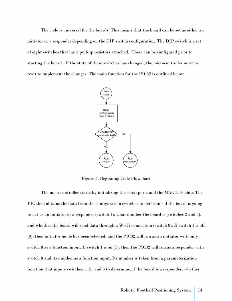
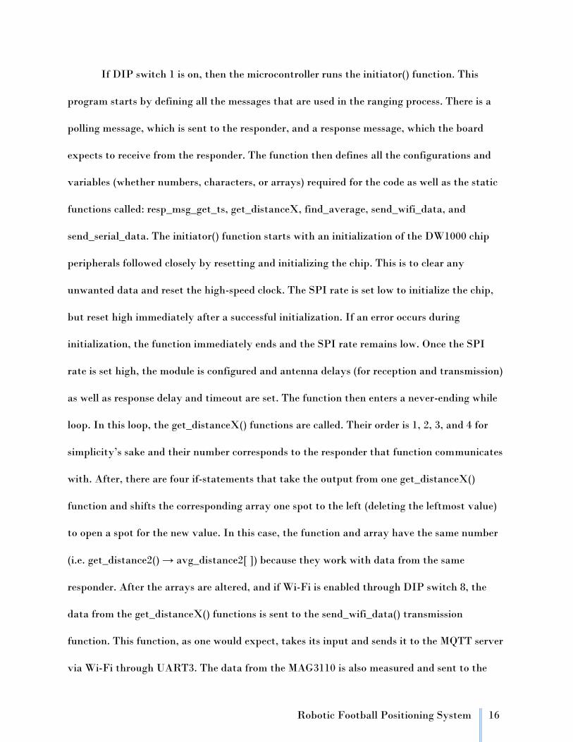
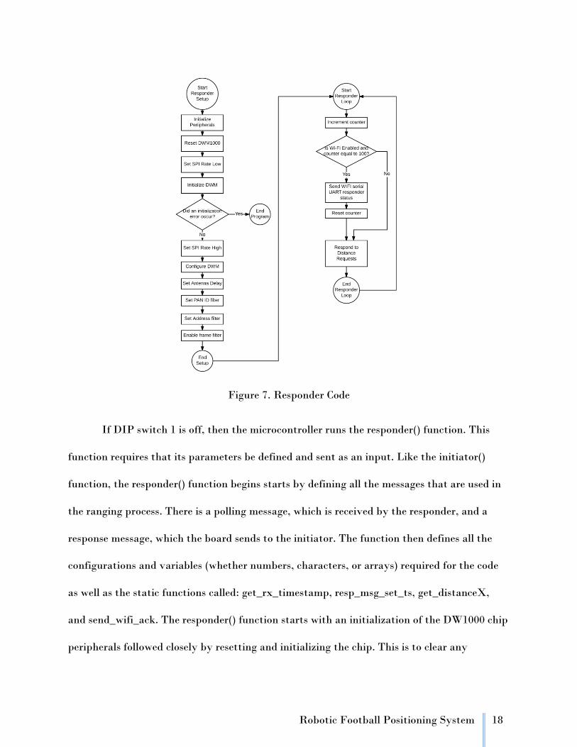
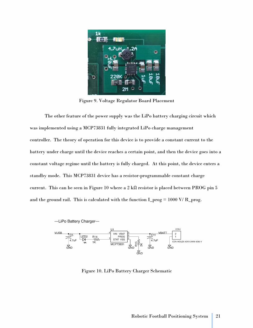
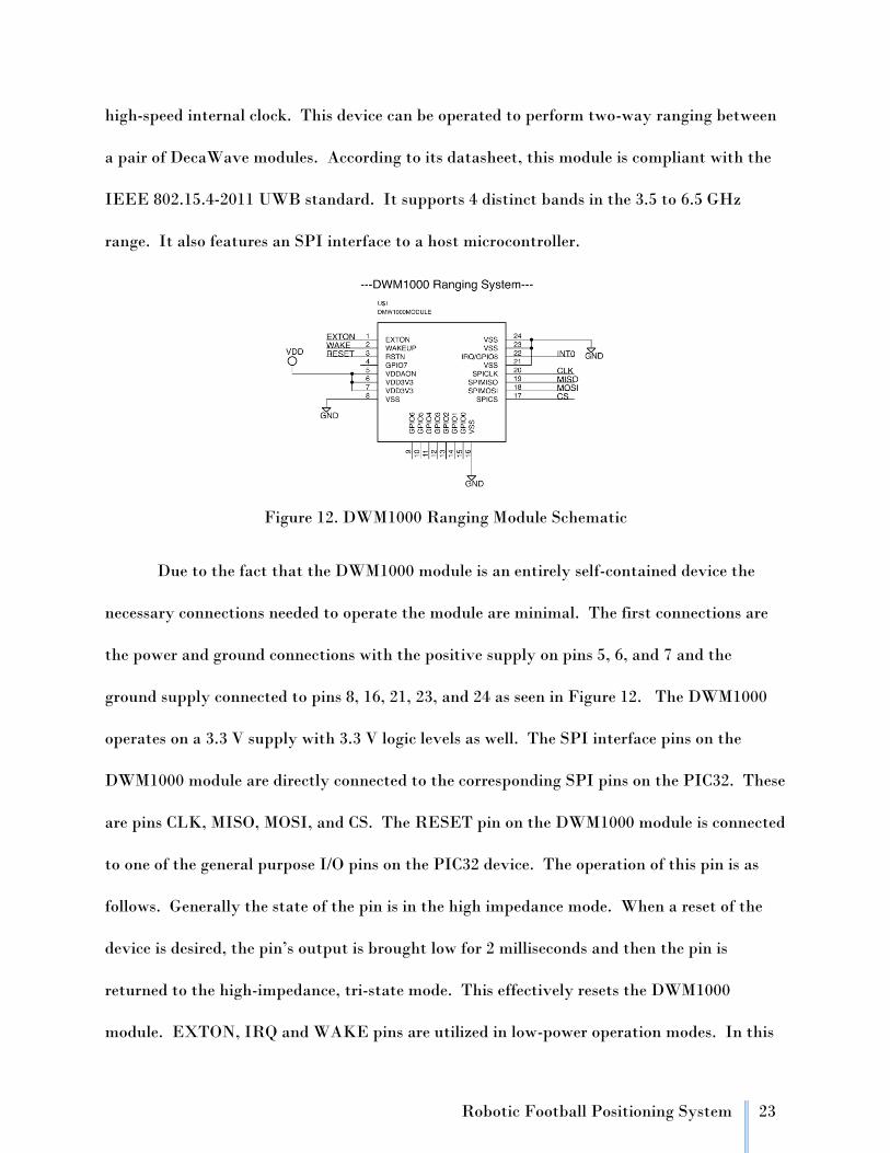
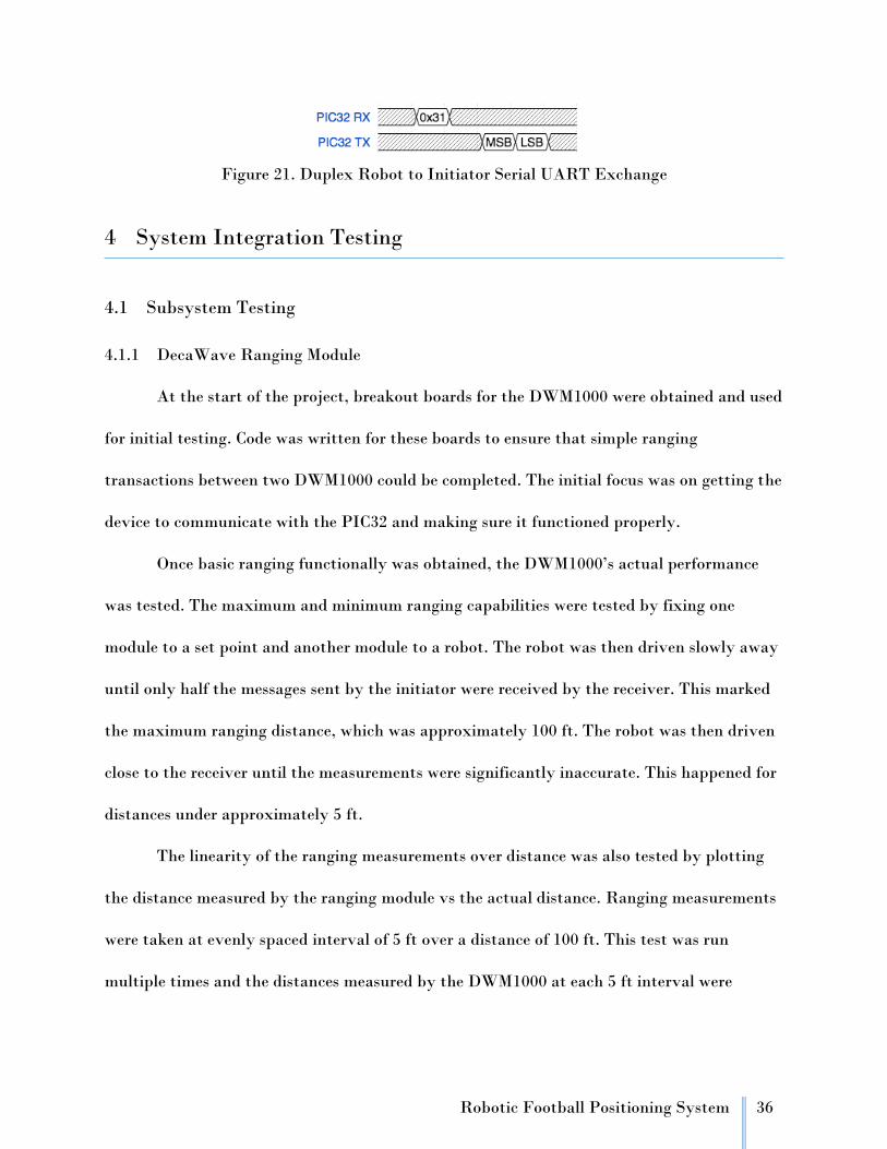