robotic arm modelling and framework for offline programming
TRANSCRIPT

Robotic Arm Modelling and Framework for Offline
Programming
Bachelor’s thesis
Valkeakoski Electrical and Automation Engineering
Fall 2019
Dat Huynh

ABSTRACT Electrical and Automation Engineering Valkeakoski Author Dat Huynh Year 2019 Subject Robotic Modelling and Offline Programming Framework Supervisor(s) Juhani Henttonen ABSTRACT
Many manufacturing industries are embracing the trend of factory automation and the adoption of robotic technology. As a result, this thesis project aimed to encourage more participation from fellow Automation Engineering students at Häme University of Applied Sciences, later referred to as HAMK, in robotics-related activities and projects. The early chapters of the thesis serve as introductory materials for beginners in the robotic field. Later parts of the thesis introduce a 3D modelling process and an offline programming (OLP) framework, both of which can be continued as standalone development projects, or they can be integrated into existing automation projects at HAMK. Although the two products of this thesis project are far from being ready to be used in the industry, they both have complete fundamental functions that can be utilised immediately. Appealing topics from the author’s perspective for future developments include robot calibrations and improvements on the OLP framework and its implementations.
Keywords Robotic modelling, robotic programming, offline programming. Pages 37 pages including appendices 4 pages

CONTENTS
1 INTRODUCTION ........................................................................................................... 1
1.1 Preamble ............................................................................................................. 1
1.2 Contents outline .................................................................................................. 2
2 ROBOTIC TECHNOLOGY ............................................................................................... 2
2.1 Robotics ............................................................................................................... 2
2.2 Industrial robotics ............................................................................................... 4
2.3 Construction of robot manipulators: joints and links ......................................... 6
2.4 Other components and structure ....................................................................... 8
2.4.1 End-effectors ........................................................................................... 8
2.4.2 Power sources and control mechanism ................................................ 10
3 ROBOT PROGRAMMING ............................................................................................ 13
3.1 Robot system ..................................................................................................... 13
3.2 Robot control .................................................................................................... 14
3.2.1 Robot controller .................................................................................... 14
3.2.2 Motion control ....................................................................................... 16
3.2.3 Connectivity of peripherals ................................................................... 17
3.2.4 Accuracy and repeatability .................................................................... 18
3.3 Robot programming .......................................................................................... 19
3.3.1 Online programming ............................................................................. 20
3.3.2 Offline programming ............................................................................. 21
4 MODELING OF DOBOT ROBOT ARM ......................................................................... 23
4.1 Motivation ......................................................................................................... 23
4.2 Geometric assests ............................................................................................. 24
4.3 Kinematic modelling .......................................................................................... 26
4.3.1 Geometry spliting .................................................................................. 26
4.3.2 Kinematic offsets ................................................................................... 27
4.3.3 Range offsets of joint angles ................................................................. 28
5 OFFLINE PROGRAMMING FRAMEWORK ................................................................... 29
5.1 Introduction....................................................................................................... 29
5.2 Overview of the framework architecture and implementation ....................... 30
5.2.1 Architecture ........................................................................................... 30
5.2.2 Visual Components 4.1 .......................................................................... 31
5.2.3 Python Dobot server/client ................................................................... 32
5.2.4 PLC-based control system ..................................................................... 33
6 CONCLUSION ............................................................................................................. 33
REFERENCES .................................................................................................................... 35
Appendices Appendix 1 DOBOT MODEL USAGE IN VISUAL COMPONENTS Appendix 2 DEMO: LIVE MOTION CONTROL FROM SIMULATION
LIST OF FIGURES
Figure 1. Robot gripper in a flexible machining cell envelope (Peng & Zhou, 2003) .... 6
Figure 2. Common robot joints (Lynch & Park, 2017) ................................................... 7
Figure 3. Symbolic representation of robot joints. Adapted from Spong et al., 2014. 8
Figure 4. Dual gripper. Photo courtesy of Robotiq (Robotiq). ...................................... 9
Figure 5. Robot manipulator and wrist configuration (HAMK Moodle, 2017). .......... 10
Figure 6. Reduction drives. Adapted from HAMK Moodle (HAMK Moodle, 2017). ... 13
Figure 7. A typical robotic system. Adapted from Spong et al., 2004 (Spong, Hutchinson, & Vidyasagar, 2004) ................................................................................... 14
Figure 8. Robot controller functions. Adapted from Kandray, 2010 (Kandray, 2010) 16
Figure 9. Programming methods and their required skills levels. Adapted from Syrjänen, 2018 (Syrjänen, 2018). .................................................................................... 20
Figure 10. The original Dobot robot arm (left) and the Dobot Magician (right) ....... 24
Figure 11. Dobot Magician model (Gero_S, 2018). ................................................... 25
Figure 12. Dobot Magician’s pen holder (left), suction cup (middle), gripper (right) (Gero_S, 2018) ................................................................................................................ 26
Figure 13. Original Dobot kinematic structure. ......................................................... 26
Figure 14. The new Dobot Magician geometries split............................................... 27
Figure 15. Incorrect (left) and correct (right) kinematic arrangement of the model. 28
Figure 16. DobotStudio interface. ............................................................................. 30
Figure 17. System schemas. ...................................................................................... 31
Figure 18. OPC UA client from Visual Components. .................................................. 32

LIST OF TABLES
Table 1. Robot classification (Bajd, Mihelj, Lenarčič, Stanovnik, & Munih, 2019) ..... 4
Table 2. Industrial robot classification based on applications (Bajd, Mihelj, Lenarčič, Stanovnik, & Munih, 2019) ............................................................................................... 6
Table 3. Programming methods. Adapted from Dolinsky, 2001 (Dolinsky, 2001). ... 21
Table 4. Dobot end-effectors (Dobot, 2019). ............................................................ 24
Table 5. Kinematic offsets. ......................................................................................... 28
Table 6. Dobot physical and modelled axes’ ranges. Adapted from Dobot (Dobot, 2019). 29
Table 7. Corresponding chosen platforms ................................................................. 31
Table 8. Visual Components product versions (columns) and supported features (rows). Adapted from Visual Components (Visual Components, 2019) ........................ 32

LIST OF ABREVIATIONS
ADS – Automation Device Specification AML – Automation Markup Language CAD – Computer aided design CAM – Computer aided manufacturing CIM – Computer integrated manufacturing CNC/DNC – Computer/Direct numerical control DC/AC – Direct/Alternating current EOAT – End-of-arm-tooling FMI – Future Market Insights HTML – Hypertext Markup Language IFR – International Federation of Robotics IPC – industrial personal computer IR – Industrial robot ISO – International Standards Organization OLP – Offline programming OPC UA – Open platform communications unified architecture PAC – Programmable automation controller PC – Personal computer PLC – Programmable logic controller RPL – Robot programming language RTDE – Real-Time Data Exchange SDK – Software development kit SME – Small to medium sized enterprise STEP – Standard for the Exchange of Product Data STL – Stereolithography UART – Universal Asynchronous Receiver/Transmitter VAL – Variable Assembly Language or VicArm Language VC – Visual Components

1
1 INTRODUCTION
1.1 Preamble
Industrial robot (IR) systems have seen a blossom during the past decade in demands of consumption and level of complexity as standalone flexible manufacturing units. According to the International Federation of Robotics’ statistics department, over 400,000 robot installations were realized in 2018 in comparison with an annual average of 115,000 units between 2005 and 2008 (IFR, 2019). With the exclusion of software and peripherals, this accounts for a total USD 16.5 billion in net worth solely in 2018, despite the recent trade conflict between China and North Americas (IFR, 2019). With traditional manufacturers embracing the ongoing trends towards computer-integrated manufacturing (CIM) and automation, IR models specialized in material handling, assembly, welding, etc. is now covering a wide variety of industries including automotive, electrical/electronics, machinery, food and beverages, etc (IFR, 2019). The potential and reputation of IRs have also reached small-and-medium-sized enterprises (SME) and individuals outside of the industrial sector like hardware shop owners. Many of which have begun to adapt IR systems into multi-axis machining applications, e.g. multi-material milling or rapid prototyping (Vergeest & Tangelder, 1996) (Shirase, Tanabe, Hirao, & Yasui, 1996). It is worth noting that this area was previously predominated by computer and direct numerical control (CNC/DNC) systems, whereas only 3-4% of the total number of robots is used for machining purposes (Abele, Kulok, & Weigold, 2005) (Pan & Zhang, 2008). This gradual migration of IR units into the sector of numerically controlled (NC) machines and machining tools is a result of each unit greater flexibility in task processing and overall lower cost against e.g. an akin volume of machining cell (Milutinovic, et al., 2010). While there are similar fundamental traits between different types of IR applications, their complexity level of tool trajectories may vary widely (Milutinovic, et al., 2010). For this reason, conventional online task programming assisted with teaching pendants is often an inefficient, time-consuming, and expensive process in non-pick-and-place applications. To simplify the teaching process, many proprietary high-level programming languages such as VAL II, AML, RPL, etc. were developed to work in conjunction with the teaching pendant at the shop-floor level. However, there remain several limitations to the online task teaching approach (Chan, Prof. Weston, & Case, 1988):
− Manufacturing downtime can be significant as a result of the geometry definition in teach mode.
− Machine-level information on the process (CAD/CAM data) available elsewhere in CIM facilities could not be utilized.

2
− Modern programming languages are more beneficial than their proprietary counterparts mentioned above.
− Operators are at risk of the hazardous work-cell/workstation Thus, SMEs with a wide variety of products requires an automatic approach in generating NC code for their corresponding manufacturing processes (Mitsi, Bouzakis, Mansour, Sagris, & Maliaris, 2005). Mitsi et al. saw the potential of an offline programming (OPL) system using CAD/CAM modules as a visual representation of the IR system to avoid problems of the teaching stage. However, this approach has also proposed new challenges, with the most common being the constraints in resource planning in terms of process and product information. Without a proper determination of IR systems (workspace elements, sensors, etc.) and CIM facilities assistance, this approach is impractical for complex manufacturing tasks (Chan, Prof. Weston, & Case, 1988). Kinematic constraints and calibration are also key factors in realizing a systematic approach to OPL solutions.
1.2 Outline of contents
This thesis project aimed to provide fundamental knowledge about the topic of robotics while encouraging other fellow automation students at Häme University of Applied Sciences, later referred to as HAMK, to participate and get more involved in the robotic sector. Thus, chapter 2 of the thesis will present the basic concepts and information on robotics and the related technology. These include the concepts of robotics and industrial robotics based on their applications, as well as the components and structure of a robot manipulator. Chapter 3 introduces the controller system for control and interact with a typical robot. This chapter also includes the concept of robot programming and the various approaches to the two categories of online and offline programming. For the thesis project to be more interactive with other students, the author constructed an offline programming (OLP) 3D model of the Dobot Magician – a compact tabletop robot arm for education or use. Chapter 4 describes in detail the modelling process and the resulting product, which is open sourced and can be used immediately. This 3D model can be used as an example for the offline programming framework presented in chapter 5.
2 ROBOTIC TECHNOLOGY
2.1 Robotics
Karel Capek in his 1920 science fiction play Rossumovi Univerzální Roboti (Rossum's Universal Robots or R.U.R) describes the term “robot”, originated from the Czech word “robota”, as an artificial labourer who

3
performs mundane and undesirable tasks for their owners. Modern robots are also derived from the same idea, as defined by a standard dictionary: “a machine that resembles a human and does mechanical, routine tasks on command” (Dictionary.com, n.d.). Despite being a young and modern sector, robotics encompasses the knowledge of many conventional technology fields: mathematics, physics, electrical engineering, mechanical engineering, automation and industrial engineering, and computer science. Over the past two decades, robotics research has grown tremendously, with the underlying power of rapid developments in software and sensor technology as well as theoretical progress in control engineering and computer vision. This advance in complexity of interdisciplinary branches like robotics and factory automation requires the emergence of the latest disciplines of engineering such as manufacturing, systems and applications, etc. (Spong, Hutchinson, & Vidyasagar, 2004). While there are many aspects evolving the fields of robotics, this paper only covers the fundamental and related concepts, including related terminology as a basis, kinematics, computer-aided design, and different types of robot programming, since the main subject evolves industrial robot arm applications integrating into factory settings and infrastructure. Nevertheless, the divergent science of robotics span across many domains, such as locomotion (e.g. flying, skating, climbing robots, or legged, wheeled robots, etc.), artificial intelligence, human interaction, legal and ethical regulations, etc. This divergence concerning both technical and social aspects ensures a balanced and effective integration of robots into both professional and domestic areas of modern society (Leenes, et al., 2017). Robots are gradually replacing humans in mundane or hazardous tasks, ranging from factory manufacturing, exploring mines and oceans, bomb defusing to daily-basis household chores like vacuuming, washing, laundry, etc. Moreover, in areas where accuracy and speed are demanding factors, such as surgical operations and anatomy, the introduction of nano-size robots is considered revolutionary (Carne, 2019). Based on their characteristic features and applications, Bajd et al. classify the most common types of robots into four main categories as demonstrated in Table 1.

4
Table 1. Robot classification (Bajd, Mihelj, Lenarčič, Stanovnik, & Munih, 2019)
Robots
Robot Manipulators
Robot Vehicles
Man-Robot Systems
Biologically Inspired Robots
Serial Land Haptic Robots Humanoids
Parallel Water Tele-manipulators Robots from animal world Micro and Nano Air Exoskeletons
2.2 Industrial robotics
Over the last few years, the industrial-robotics market has been on the rise, with over two million industrial robots installed and operated on factory floors and other commercial sites in 2018 (IFR, 2019). This prevalent growth is mainly driven by the gradually decreasing robot prices in comparison with the upward rising labour costs. In his 2017 article “Automation, robotics, and the factory of the future”, Tilley presented a significant rise of nearly 120% in labour compensation from 1990 – 2017 in comparison with a gradual drop of 50% in the robotics counterpart (Tilley, 2017). Another key factor in the adoption of robotics technology in the industrial sector is social motivation. In situations where facing toxic and hazardous working conditions is inevitable, the benefit robot as a substitution for human workers can overshadow economic concerns (Bajd, Mihelj, Lenarčič, Stanovnik, & Munih, 2019). Thus, many industrial robots were originally designed to carry human-like characteristics while having at least the same level of performance. Nevertheless, in terms of speed, precision, repeatability, and reliability, their modern skills go far beyond those of even the best worker. The human characteristics of the robot include a mechanical arm, the ability to make decisions based on sensory inputs, and the ability to communicate with its environment for industrial applications. In addition, the ability to be programmed and reprogrammed qualified IRs for the programmable automation category. Therefore, an industrial robot is defined by the International Standards Organization (ISO) in the ISO/TR/8373-2.3 standard as: - …an automatically controlled, reprogrammable, multipurpose
manipulator, programmable in three or more axes, which can be either fixed in place or mobile for use in industrial automation applications (International Organization for Standardization, 2012).
Albeit the first industrial robot applications were intended to be standalone solutions, many modern robotics systems are recognized for their ease of integration into any factory implementations (Kandray, 2010). Recent rapid progress in computer hardware, software development, and

5
networking technologies enables the maturity of the robotics field in terms of reliability and capability while maintaining lower costs in robot production. Accordingly, more and more robot manufacturers are developing and shipping their related products as modular, plug-and-play units with very competitive offerings and pricings (Tilley, 2017). A standard IR system is designed for the ease of assembly, installation, and network establishment. The components are compatible with most modern standard network protocols and thus are able to automatically register themselves to any production systems using straightforward network wiring. Such simplicity becomes the main motivation for industrial designers to integrate robots into the majority of their applications. This approach increases the flexibility of the overall production system, as commissioners are able to quickly apply modifications to a manufacturing system for new production runs. As a result, companies can expect a much faster return on capital investments, since less repetition is required in single-task execution, equipment design, procurement, and commissioning (Tilley, 2017). In terms of process platform integration, Bajd et al. divided industrial robots into three groups found in Table 2 using their applications. The first two groups involve industrial robots working in automated manufacturing cells. These automation work cells incorporate groups of manufacturing stations, each assigned with a specific task or process (Kandray, 2010). As demonstrated in Figure 1, typical robots in machining cell envelopes are often seen working in conjunction with programmable logic controllers (PLC), part feeders, CNC machines, conveyors, etc., either taking a leading role or tending the manufacturing process (Peng & Zhou, 2003). Master robots often take responsibility in tasks such as welding (spot, arc, laser), coating, machining, etc., while the processes involving slave robots may vary among different types of material handling such as palletizing, press loading, parts feeding, etc. The third type of robot tackles unconventional applications and industrial sectors: inspection and quality assurance, maintenance and repair, food packaging and decorations, textile and clothing, and construction (Bajd, Mihelj, Lenarčič, Stanovnik, & Munih, 2019). Quality assurance and testing robots are commonly used in the electronics industries, where electric parameters of every component are frequently tested during production runs. The food and textile industry propose unique challenges in material handling, since the workpiece nature is often non-rigid, and certain hygiene requirements must be met in food processing. Autonomous and teleoperated robots are opted-in for maintenance and repair tasks unsafe for human, such as servicing and maintenance for nuclear facilities, highways, power grids, etc.

6
Figure 1. Robot gripper in a flexible machining cell envelope (Peng & Zhou, 2003)
Table 2. Industrial robot classification based on application (Bajd, Mihelj, Lenarčič, Stanovnik, & Munih, 2019)
Industrial Robots
Work cell master Work cell slave Special applications
Welding Material/Workpiece handling
Quality assurance, inspection, testing
Painting, coating, sealing
Palletizing, parts feeding
Maintenance and repair
Machining Die casting Food industry
Assembly Flexible fixturing Textile and clothing industry
Construction
2.3 Construction of robot manipulators: joints and links
As discussed above, the most effective and powerful robotics systems today are the industrial robot arms or robot manipulators that can substitute and outperform human workers in labour-heavy and monotonous jobs or hazardous working environments. The robot manipulator commonly consists of a set of rigid bodies, also known as links, mechanically assembled together using different types of joints, as demonstrated in Figure 2 by Lynch and Park (2017). According to Lynch and Park, each joint is only allowed to connect two links simultaneously.

7
As can be seen from the graph, the revolute joint (R), also referred to as a hinge, enables relative rotation between the two connected links; meanwhile, links connected by the prismatic joint (P) are able to perform relative linear movements. Aside from these two most typical joints, robot manipulators may include other types of joints such as the helical (H) and cylindrical joints (C), each allows simultaneous (H) and independent (C) rotational and translational motion respectively; the universal joint (U) which includes a double revolute joints in an orthogonal configuration; the spherical or ball-and-socket joints (S), which allows a three-dimensional rotation similar to a human shoulder. The chain combination of several joints and links form a kinematic structure providing a mathematical and geometrical approach to describe the spatial positioning of the manipulator’s overall structure at a given time. Spong et al. in their book Robot Dynamics and Control (2004) described the two links at any given revolute or prismatic joint of a robot manipulator as 𝑙𝑖 and 𝑙𝑖+1, while the rotational or translational axis that joint is denoted by 𝑧𝑖. The variable describing the displacement of adjacent rigid segments is defined as 𝜃𝑖 for the R-type joint or 𝑑𝑖 for the P-type counterpart (Spong, Hutchinson, & Vidyasagar, 2004). As illustrated in Figure 3, these mathematical representatives of a robot physical configuration answer the fundamental question of robotics – identifying the robot position in the physical world. As a result, precise controlled robot movements powered by motors and actuators is achieved by converting the geometric information into electrical signals.
Figure 2. Common robot joints (Lynch & Park, 2017)

8
Figure 3. Symbolic representation of robot joints. Adapted from Spong et al., 2014.
2.4 Other components and structure
2.4.1 End-effectors
Aside from joints and links, industrial manipulators usually include an end-effector or end-of-arm-tooling (EOAT) attached to a specific segment, often called wrist. End-effectors are different tools extending the robot capabilities and applications range, such as gripper or suction cup for material/work-piece handling, milling tools for machining, spray nozzle for paint coating, etc. In many applications, more than one end-effector per manipulator is required, and the process of tool change is often carried out automatically by the robot itself. Depending on the situations, a special dual EOAT set up as shown in Figure 4 can be utilized for better efficiency while trading the flexibility of the device. The diversity in EOATs and how it dictates the robot application types is an advantage for small and medium sized businesses (SMEs) with small batch sizes and large product agglomeration (Tilley, 2017). The essential flexibility and simplicity of the robot to be rapidly reconfigured and redeployed significantly reduces the number of single task repetitions to justify the purchasing and commissioning costs (Tilley, 2017). Simultaneously, the majority of end-effector supplies in the market comes from independent manufacturers with a significant product variety ranging from conventional formats (mechanical, pneumatic, or magnet) to specialized tools for handling specific materials (Aljarboua, Santhanam, Teulieres, Thomsen, & Tilley, 2019). Therefore, the cost of EOAT units may significantly vary from being superficial to higher than the robot itself (Bajd, Mihelj, Lenarčič, Stanovnik, & Munih, 2019). In cases where the various EOATs available on the market

9
cannot meet the specifications, special tools for particular applications are often designed by engineers from scratch or from commercial EOATs base models.
The kinematic chain linking between the robot manipulator and the end-effector is described as a robot wrist. A typical wrist always consists of revolute joints, and the most popular configuration commonly seen in modern robot applications is a spherical wrist (Spong, Hutchinson, & Vidyasagar, 2004). This configuration simplifies the spatial identification process of a robot manipulator to a great extent by separating its overall kinematic structure into two independent analyses. The first three positional degrees of freedom are decoupled by examining three or more joints of the robot arm. The remaining number of orientational degrees of freedom is then determined by the degrees of freedom of the wrist. This number is application dependent, and it usually varies from one, two, or three. Figure 5 illustrates a typical robot manipulator attached with a three degrees of freedom spherical wrist. The three revolute joints in this type of wrist are denoted as roll, pitch, and yaw.
Figure 4. Dual gripper. Photo courtesy of Robotiq (Robotiq).

10
Figure 5. Robot manipulator and wrist configuration (Aimo, 2017).
2.4.2 Power sources and control mechanism
Reliability and availability are the fundamental requirements of any power source actuating a robot arm. There are three main types of robotics powering systems, namely electrical systems, hydraulic systems, and pneumatic systems. The hydraulic system is a closed-loop system utilizing the pressurized flow of oil-based hydraulic fluid to create translational or rotational motions of actuators that enables the desired robot movements (Kandray, 2010). The nature of pressurized fluid gains hydraulic systems a high power-to-size ratio, hence they are considered unrivaled in terms of responsiveness and torque delivery (Bajd, Mihelj, Lenarčič, Stanovnik, & Munih, 2019). Thus, hydraulically actuated robots are the primary choice in performing heavy loads lifting tasks. However, hydraulic-based power systems present many serious concerns throughout the stages of their lifecycle (Kandray, 2010). The upfront cost of hydraulic systems relatively high, since they require extra support from different mechanical and electrical components such as motorized pumps, pipelines, control valves, etc. to function properly. These components also add up the energy and emission footprint of the overall system during operations. Operators are also at risk of component failure under high pressure and temperature, potentially leading to severe injuries or death. Maintenance for hydraulic systems is to be carried out frequently since the constructions are

11
subjected to leaks and degradation under constant heavy workloads. Fire-resistance of the hydraulic fluid is another key factor to be considered since they are oil-based and often not available on factory sites. In terms of design language, pneumatic systems share some similar fundamental principles and components in comparison with their hydraulic counterparts (Kandray, 2010). Both types of actuators function based on pressurized substance flow while being powered by an additional support system consists of control valves, lines, etc. However, performance capability is the key factor in diverging the two systems. Accuracy in position control and speed of pneumatically powered robots is difficult to achieve because of the unstable nature of compress air. This constraint limits the application range of pneumatic robot systems to simple pick-and-place type operations. Since pneumatic-based robots are opened loop systems, they often use adjustable mechanical stops for position control to some extent. On the other hand, opened loop designs do not require a separate return pipeline; hence, the complete piping structures are simplified, and costs are reduced in terms of installation and maintenance. In addition, most factory floors provide their own air compression system available for use immediately, further increasing the savings. Air-based actuators are also subjected to leaks, but environmental concerns are insignificant. Currently, robots powered by electrical actuators are recognized as the most popular systems of choice for often being cheaper, cleaner, and quieter than other systems (Spong, Hutchinson, & Vidyasagar, 2004). Precise control of electrically powered robots over their velocity, acceleration, and position is achieved through a closed-loop system where the relevant data is encoded into electrical command signals (Kandray, 2010). Electrical systems are driven by alternating current (AC) or direct current (DC) motors. AC servomotors have the benefit of being stable and light while requiring seldom maintenance. On the other hand, while relying on frequent brush replacements to function properly, DC motors deliver more torque, qualifying them for strength demanding tasks. Aside from the motors, each electrical robot also includes a support system of reduction drives. The supporting drives generate revolute speed reduction and torque amplification to produce desired links and joints motions (Kandray, 2010). The most prevalent types of reduction drives are illustrated in Figure 6. Rotary motions are performed by synchronous belt drives, train of spur, worm or bevel gears. Other than synchronous timing, belt-type rotary drives can either be a v-groove or flat belt, although they are seldom used in applications due to the high possibility of slippage. Worm gear drives are used for 90 degrees rotational conversion, while bevel gears may be used for both 45 and 90 degrees of axis rotation. For linear or translational motions, the use of ball-screw gear drives provides a high level of precision in a small form factor. For greater torque-to-size ratio, harmonic drives are an appealing choice, although the mechanism principle behind them is difficult to describe and thus will not be

12
mentioned in this paper. Every gear system can be described using the gear ratio formula:
𝐺𝑅 =𝑁𝑂
𝑁𝐼 (1)
Where: 𝑁𝑂 is the number of teeth on the output or driven gear. 𝑁𝐼 is the number of teeth on the input or driver gear. Thus, the gear transfer function can be described as:
𝑇𝑅 =𝑉𝑂
𝑉𝐼=
𝜃𝑂
𝜃𝐼=
1
𝐺𝑅 (2)
Where: 𝑉𝑂 is the revolutions per minute (rpm) of the driven gear. 𝑉𝐼 is the rpm of the driver gear. 𝜃𝑂 is the angular rotation of the driven gear. 𝜃𝐼 is the angular rotation of the driver gear. 𝐺𝑅 is the gear ratio

13
Figure 6. Reduction drives. Adapted from HAMK Moodle (Aimo, 2017).
3 ROBOT PROGRAMMING
3.1 Robot system
A typical robot system encompasses more than just a series of mechanical bodies and linkages. As illustrated in Figure 7, a functioning robot system consists of:
− Robot manipulator
− Power source system
− Controller

14
− Teach pendant
− Different end-effectors or end-of-arm tooling
− A wide range of connected devices, including internal and external sensors and periphery equipment
− Network and storage system Another essential integration of the system is the robot program and the underlying software architecture, since the configuration and behaviour of which can impact the overall performance and dictate the subsequent application scope (Spong, Hutchinson, & Vidyasagar, 2004). In subchapter 2.4, we have already discussed different types of power sources and EOATs in terms of technical arrangements, advantages, disadvantages, and application niches. In the following subchapters, the focus would be to describe different aspects of robot programming, from hardware requirements and capabilities to the fundamentals of programming software, methods, and techniques. The later section on programming concepts and techniques will also serve as a guideline basis for the upcoming empirical process.
Figure 7. A typical robotic system. Adapted from Spong et al., 2004 (Spong, Hutchinson, & Vidyasagar, 2004)
3.2 Robot control
3.2.1 Robot controller
A recent study from the Future Market Insights (FMI) reported a sustainable growth in demands for the industrial robot controller market motivated by the uprising trends and embracement of factory automation (Future Market Insights, 2019). The year 2018 saw a relative approximate market value of USD 632.6 million, which will receive another 9.1 percent

15
increase during the upcoming course of 2019 to 2029 according to FMI. The automotive and electronics/semiconductor industry with their continuous growing supply chains has been the two most dominant customers throughout the market for industrial robots and robot controllers (Brog˚ardh, 2009). The advent of Industrial Internet of Things (IIoT) innovations and adoption of human-robot collaboration enables better optimization for robot controllers while encouraging more open-source solutions; thus, modern robot controllers are now commonly integrated into programmable logic controller (PLC), programmable automation controller (PAC), personal computer (PC), industrial PC (IPC), embedded systems, etc. (Hoske, 2015). At its most basic form, a robot controller is any computing hardware serving three main purposes as described in Figure 8 (Kandray, 2010):
− Robot motion control
− Peripherals control
− Operator interface The controller unit must first be able to control the manipulator motions through its actuators. Secondly, the controller can recognize and communicate with different input sensors, end-effectors, external actuators, etc., bridging the gap between the robot and its periphery devices. Finally, the controller is served as an entry point for manual robot control and program editing and execution.

16
Figure 8. Robot controller functions. Adapted from Kandray, 2010 (Kandray, 2010)
3.2.2 Motion control
Industrial robots’ classification as discussed in subchapter 2.2 could also be determined based on the type of trajectory motions generated by the controller executors. The lowest level of control complexity for a robot manipulator is known as the limited sequence control (Kandray, 2010). Industrial robot systems at this level are opened loop devices with no feedback system, and their movements are predefined with mechanical hard stops (Spong, Hutchinson, & Vidyasagar, 2004). After the control signals are sent to the actuators, the lack of feedback inputs prevents any further subsequent verifications on the execution status and robot position. Despite the limit in performance capabilities, this control method simplifies the requirements for the controller, allowing standard units like a programmable logic controller (PLC) to be sufficient for limited-sequence controlled robots.

17
On the other hand, the performance level of closed-loop control robotic systems is dictated by the capabilities of their feedback equipment and systems. The simpler type of system in this category is the point-to-point control robot (Spong, Hutchinson, & Vidyasagar, 2004). This type of robot allows the end-effector to be sequentially positioned in accordance with a predefined set of discrete spatial points. This demands only a certain level of axes’ positioning feedback since there are no tool path restrictions. On the controller side, the introduction of a spatial points set reserves a small storage volume, while requiring a proper user interface, e.g. a teach pendant, for teaching and editing the sequence. The next level of closed-loop control method is continuous path control, where the entire tool trajectory, velocity, and acceleration are planned ahead. The planning process could be carried out manually or with the support of simulations software. During run-time, the program requires more computing resources than other control processes, since the continuous streams of commands are being executed based on the simultaneous unceasing encoded data of every individual axis movements. Thus, the level of accuracy, performance, and capabilities of the robot system is a direct ratio of the provided computational power. Such flexibility makes continuous path control robots the most popular system of choice throughout various industries. Their applications cover a wide variety of precision demanding tasks, such as seam arc-welding, machining, special grasp and place jobs, etc. (Kandray, 2010).
3.2.3 Connectivity of peripherals
Many industrial tasks mentioned throughout this paper are almost always performed with the cooperation of an industrial robot and one or more peripheral devices, including external sensors, external actuators, devices, tools with their own sensors (Patent No. EP1749249A1, 2003). Thus, the communication and control of the robot over these peripherals are an important aspect of robot control (Kandray, 2010). Along with other computer hardware equipment, the robot controller continues to increase in speed and performance, enabling multitasking and independence in robots through enhanced connection quality and better diversity in periphery equipment (Godwin, 1998). Godwin stated in his study that the state-of-the-art work-cells’ controller solutions are getting better flexibility in implementation strategies, as they often share similar functionality and fundamental design traits in microchip architecture. Native robot controllers can now take on the leading role in work-cells with low complexity in control hierarchy and little requirements for speed-critical tasks. Aside from robot movements, controllers in these applications handle also end-effector action, e.g. gripper open/close; external devices such as sensors, slider, conveyor motors, etc. This type of arrangement unifies the connections and software development into one central platform; thus, it increases the simplicity and lowers the cost of implementation.

18
In a larger manufacturing process involving a significant amount of industrial equipment and/or multiple robots working in conjunction, the robot controller can have interchangeable roles with a PLC or IPC. The classifications and hierarchy decisions are made based on the robot classification discussed in subchapter 2.2. Robot masters have their controller focuses on complex axes’ movements, while other PLC handles the local peripherals’ signals and processes. PLC masters control the overall operation of the manufacturing process while sending high-level commands for other local manipulator controllers to trigger sequences of robot movements. In a distributed system, PLCs and robot controllers are implemented with equal in control status to increase the flexibility of the workstations, since they are most often designed to be independence from others for the ease of reconfiguration and redeployment. In many applications, one or more of the above-mentioned setups may co-exist in the same hierarchy.
3.2.4 Accuracy and repeatability
Accuracy and repeatability are the two most important aspects in assessing the performance of an industrial robot system (Dolinsky, 2001). The term accuracy refers to the ability of a robot manipulator to achieve the smallest deviation from the pre-programmed positions and orientations of its tool or end-effector. Meanwhile, repeatability or precision indicates the possibility of the robot to reproduce any previous reference position of the end-effector in its workspace. Most modern robotic systems while having great repeatability performance often struggle to achieve an acceptable level of accuracy movements (Płaczek & Piszczek, 2018) (Şirinterlikçi, et al., Spring 2019). Płaczek and Piszczek pointed out that the problem is inevitable regardless of a well-designed environment and a well-prepared program since the main reason is coming from the limitations in the current feedback system. A typical robot manipulator does not include a method to directly measure the spatial positions and orientations of its end-effector. Rather, the numbers are calculated using positional encoders throughout the robot structure and dimensional measurements of the mechanical parts. This exposes the process to errors and uncertainties in computation; robot construction defects such as bending, compressing, etc.; moving parts effects, e.g. gear backlash; etc. Thus, an excellent accuracy level of a robot system must correspond to an extremely rigid mechanical structure, which can be difficult and expensive to achieved (Spong, Hutchinson, & Vidyasagar, 2004). However, methods such as robot teaching offsets, calibration, and direct sensing with vision or laser could help improve the accuracy level of a robotic system. On the other hand, the repeatability level of a robot only depends on the ability of its controller to deliver the same set of electrical signals with a small margin of error. This feature is called controller resolution, which
19
refers to the smallest motion deviation a controller can generate (Spong, Hutchinson, & Vidyasagar, 2004). Rapid advance and improvements in the electronics and semiconductor industry allow increasingly better controller resolutions, resulting in better robot performance in both accuracy and repeatability.
3.3 Robot programming
The robot classifications in terms of applications, work-cell roles, motion control, power sources, etc. discussed in previous chapters have a significant impact on the choice of their programming method (Kandray, 2010). For an opened loop pneumatic robot in playback applications, the workspace is contained using mechanical and electrical limit switches, and the task sequence steps are relatively simple and usually executed by a programmable logic controller (PLC). On the other hand, most modern servo-driven robot systems are equipped with more complex controllers and a separate system to communicate about the robot positions using higher-level programming languages, thus provides more performance and capabilities. At its core, robot programming boils down to two fundamental tasks, regardless of their applications:
− Robot motion programming
− Sequencing/work-cycle programming Although there are many programming methods, most can be distinguished by the nature of the programming process, of which they reside in the two categories of motion programming and robot language programming (Kandray, 2010). In many cases, these two categories are rephrased into online and offline programming respectively, to describe the whereabouts of the programming process and personnel during the period (Syrjänen, 2018). Online programming typically takes place at the factory floor level or inside the robot work-cell, where the operators and technical specialists interact directly with the robot. The offline programming process does not require physical contact with the robot but gets carried out and tested instead in simulations environment outside of the manufacturing facilities. The following subchapter discusses more in detail the two online and offline approaches/styles of robot programming, as they are conventionally accepted and somewhat covers both motion and robot language programming mentioned earlier. In fact, Syrjänen suggests in his bachelor thesis (2018) an arrangement for these different programming categories in the order of technical skills involved. This arrangement is illustrated in the following Figure 9.

20
Figure 9. Programming methods and their required skills levels. Adapted from Syrjänen, 2018 (Syrjänen, 2018).
3.3.1 Online programming
Online programming was adopted immediately early in the robot industry for its simplicity and intuitiveness as a solution, while offline programming methods and practices were still immature and underdeveloped (Yong, Gleave, Green, & Bonney, 1985). As described in table 3, online programming methods by nature can be classified into motion teaching/programming and high-level robot language programming (Dolinsky, 2001). Motion teaching is the process of physically guiding the robot manipulator through a set of desired positions and orientation, while simultaneously defined program instructions (Kandray, 2010). The guiding methods vary in levels of complexity depending on the control mechanism and applications discussed in subchapter 5.2.2 (Dolinsky, 2001). For pick-and-place pneumatic robots, the simplest manual method is used which often involves basic equipment setup and adjustments for mechanical stops, limit switch, etc. In continuous path control systems, the manual walkthrough or leadthrough method is used. These two methods require the operator to manually move the robot arm through a path of continuous points. The points are stored locally and reserve a significant amount of memory and storage of the controller. For situations where manual guiding of the manipulator is impractical, a handheld teach pendant is used to power-guide the robot, and hence the method is called powered leadthrough. Regardless of the teaching methods, Kandray described in his book the process of motion programming using a general procedure as follow (Kandray, 2010):
− Define a start/home position of the manipulator and an instruction to move the end-effector to such position.

21
− Input the logic instruction(s) for the end-effector/EOAT and/or relevant peripheral devices as required in the process.
− Input a moving command to reach the next point in space with correct orientations and relevant parameters such as velocity, moving path, accelerations, etc. A previously stored continuous path, if any, could be executed instead.
− Input the logic instruction(s) for the end-effector/EOAT and/or relevant peripheral devices as required in the process.
− Repeat step three and four until the sequence is complete. The above-mentioned process can often be tedious and time-consuming while reducing the uptime and output of the robot. Some robot units are double purchased for a given application as a result; one unit becomes the programming and testing platform, while the other goes to production (Kandray, 2010). The use of higher-level robot programming languages eases the need for significant service downtime, by isolating the logic programming process outside of factory sites. The logic sequence program now takes a modern shape and benefits from high-level/human-readable languages such as better structure and abstract level, built-in support for native geometric entities, high-level commands, etc. (Dolinsky, 2001). Although most modern robot languages are proprietary, such as VAL, RCL, RPL, etc., they were fundamentally similar and often simpler versions of modern programming languages (Syrjänen, 2018). As a result, the programming and testing process can be carried out more efficient while minimizing the loss in the production time of the robot, which is mainly used for defining the arm positions. Nevertheless, the many advantages of this approach come at the cost of a higher level of sophistication and computation from the robot controller side (Dolinsky, 2001). First, the controller must first be able to interpret and execute the program during runtime. Second, the robot controller often must implement an inverse kinematic model of the manipulator structure to translate the end-effector positions to the axial movements. This could result in the overall accuracy of the operation.
Table 3. Programming methods. Adapted from Dolinsky, 2001 (Dolinsky, 2001).
Robot Task Motion programming
Manual
Walkthrough
Leadthrough
High-level programming
3.3.2 Offline programming
As the adoption and demand robotics in factory automation rises, a need is raised for a more flexible, efficient, and intuitive approach for robot programming other than the conventional online counterpart (Neto & Mendes, 2013). The concept of offline programming (OLP) elevates the

22
method of robot language programming by completely isolating the programming process from the physical robot manipulator, minimizing the number of downtime interventions to lower costs (Dolinsky, 2001). OLP solutions are often delivered in software packages called OLP software or computer-aided robotics (CAR) software (Neto & Mendes, 2013). Most manufacturers’ or aftermarket OPL software packages allow the transformation of work-cells and robotic systems on factory floor level into interactive simulations of environments and systems available remotely and virtually. A typical OLP system encompasses the following components, as suggested by Dolinsky:
− Computer-aided-design system/package contains libraries of geometry, 3D module, 3D importer/exporter.
− Modelling and simulation modules are environments for kinematics and dynamics modelling and simulation.
− Visualization/interaction viewport displays intuitive graphical 3D representations of the factory environment and animations of the manufacturing process
− Standard library of robot models is a collection of ready-made modules provided by different robot manufacturers
− Program interpreter/generator create the robot-ready programming sequence automatically from the simulation process.
Aside from the reduction in robot downtime, Carvalho et al. present some other benefits of using the OLP approach (Carvalho, Siqueira, & Absi-Alfaro, 1998):
− Reduction in human health-related risks caused by interaction with hazardous manufacturing facilities.
− The flexibility of the overall work-cell and its units is increased.
− Tasks planning optimization and validations are carried out faster and more efficiently
− Previously planned routines and other parts of the program can be reused.
− The information model of the process, e.g. CAD/CAM data, can be imported directly to the simulation to increase the system accuracy in a straightforward manner.
In contrast, some drawbacks of the OLP approach are discussed by Neto and Mendes as follow (Neto & Mendes, 2013):
− The relatively high upfront costs in software and staff training are difficult to justify for many small and medium-sized enterprises (SMEs).
− Accurate models of the robot manipulator and their working environments, as well as information on the manufacturing process, must be prepared in advance.
− Propper calibration between the simulation and the real-world environment must be carried out by experienced technicians to avoid significant inaccuracies of the robot system during runtime.

23
4 MODELING OF DOBOT ROBOT ARM
4.1 Motivation
In June 20015, Jerry Liu and his six other classmates launched a Kickstarter project which raised USD 650 000 for a desktop robot arm named Dobot (Sin, 2017). One year later, these Chinese students from the Academy of Science in Jiangsu went on and released the second version of Dobot, the “Magician”, with some upgrades in terms of look, size, performance, and capability. This 4-axis robot arm has the maximum payload of 500 grams with 0.2 millimeters of precision, weighing only 4 kilograms (Dobot, 2019). The robot comes with 5 different types of end-effector, presented in Table 4. The aim of the company for this product was, according to Liu, “…to make something affordable so people could create”. Thus, Dobot Magician becomes a practical choice for robotics education and training across many academies and universities. The aim of this thesis project is to build an offline programming framework for the Dobot platform, using Visual Components 4.1 (VC) as the main offline programming (OLP) software package, which is discussed in subchapter 3.3.2. However, at the time of implementation, the standard library of robot models in VC only includes the early Kickstarter version, which is different in size and lacks the support for the various end-effectors on the Magician model. This inspired the author to implement the newer 3D model version of the Dobot arm to be utilised for the project. This process is discussed in detail in the following subchapter. Figure 10 showcases the visual difference between the old (left) and new (right) model of the Dobot Magician.

24
Figure 10. The original Dobot robot arm (left) and the Dobot Magician (right). Photo courtesy of Dobot.
Table 4. Dobot end-effectors (Dobot, 2019).
3D printer kit Print size (L x W x H) 150 x 150 x 150 (mm)
3D printing material PLA
Resolution 0.1 mm
Laser engraver Power consumption 500 mw
Type 405 nm (blue laser)
Power 12V, TTL trigger (with PWM driver)
Pen holder Pen diameter 10 mm
Vacuum suction cup Suction cup diameter 20 mm
Pressure -35 KPa
Gripper Range 27.5 mm
Drive Type Pneumatic
Force 8 N
4.2 Geometric assests
The actual construction of the Dobot Magician 3D model is out of the scope of this project. Thus, the model demonstrated in Figure 11 was fetched

25
from the company’s customer support portal. The document includes both STEP and STL format for the original model, and three out of five end-effector models for the robot, which can be seen in Figure 12. However, the model was not ready for situations, since there has not been any kinematic structure integrated within. The following subchapter discusses the implementation of the modelling process using Visual Components 4.1 as the simulation environment.
Figure 11. Dobot Magician model (Gero_S, 2018).

26
Figure 12. Dobot Magician’s pen holder (left), suction cup (middle), gripper (right) (Gero_S, 2018)
4.3 Kinematic modelling
4.3.1 Geometry spliting
The kinematic template from the original Dobot model was utilized as a base where the new model is constructed. The Dobot modelling information can be obtained and interacted with through the Component Graph located under the Modelling tab in Visual Components 4.1. As can be seen from Figure 13, the old version kinematic structure contains six levels of indentations, representing the hierarchy of the robot components. Based on this structure, the geometries of the newer Dobot Magician are split accordingly as demonstrated in Figure 14.
Figure 13. Original Dobot kinematic structure. Photo courtesy of Visual Components and Dobot.

27
Figure 14. The new Dobot Magician geometries split. Photo courtesy of Dobot and Visual Components.
4.3.2 Kinematic offsets
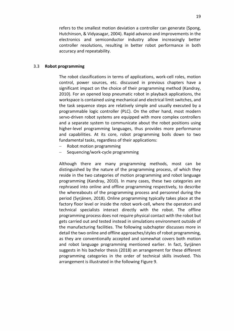
After splitting, the geometries of the Dobot Magician model could be placed into the kinematic template from the older version model. However, as can be seen from Figure 15 (left), the kinematic links (yellow spheres) were not connected to the correct locations of the components’ geometries. To combat this problem, the spatial positions of the kinematic links must be adjusted with offset values. These values are measured in distances the displacements of the links in comparison with the base frame of the robot model. This base frame is illustrated with the red, green, blue arrows in Figure 15. The displacement distances were both taken from actual measurements of the device and from the official physical specifications of the robot arm. The measured offset values are then edited accordingly as denoted in Table 5. After applying the offsets, the kinematic links are now attached to the correct geometries as shown in Figure 15 (right). The 3D model is now almost ready for further simulation and offline programming related tasks. The following subchapter discusses the deviation and adjustment in joints angles range between the 3D model and the physical unit.
28
Figure 15. Incorrect (left) and correct (right) kinematic arrangement of the model. Photo courtesy of Dobot and Visual Components.
Table 5. Kinematic offsets.
Links coordinates New values
L01X 142.6
L12X 0
L12Y 0
L23X 97.676468
L23Z 93
L34X 85
L34Z 120.1
L45X -34.5
L45Z 30.99
L56X 100
L56Z 40.585
MountplateOffset -34.5
4.3.3 Range offsets of joint angles
This subchapter describes the joints’ angle range adjustment of the Dobot Magician 3D model in accordance with the official specifications of the real-world unit. As discussed in the previous subchapter, the model uses the simulated based frame coordinates as a guide for its kinematic structure. Therefore, the resulting joints angles correspond to a different value range comparing to those specified and used by the manufacturer.

29
The default ranges for each axis of the Dobot Magician arm are showcases in column 2 of Table 6. The readjusted values of the ranges as denoted in column 3 are measured using the provided tools in Visual Components; thus, they might affect the final accuracy of the simulation system. However, robot calibration by itself is another potential thesis topic, and hence, it will not be covered in this paper. Nevertheless, the construction of a virtual representation of the robot arm provides a sufficient foundation for the upcoming introduction of the offline programming framework.
Table 6. Dobot physical and modelled axes’ ranges. Adapted from Dobot (Dobot, 2019).
Axis Default range (degree) Simulated range (degree)
Joint 1 base -135 – 135 -135 – 135
Joint 2 rear arm 0 – 85 140 – 55
Joint 3 forearm -10 – 95 49 – -53
5 OFFLINE PROGRAMMING FRAMEWORK
5.1 Introduction
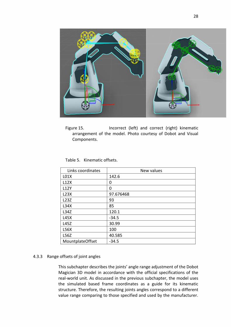
The aim of the framework is to presents a practical method of offline programming (OLP) implementation for the Dobot robot arm. By default, the robot manufacturer includes a free-to-use interface called DobotStudio which can be downloaded directly from their official web site. As can be seen from Figure 16, the software is a user-friendly portal for beginners that provides easy access to the basic eight functions of the robot arm. The interface supports basic playback teaching as well as function blocks programming and scripting with Python. Users are also able to integrate their own HTML/JavaScript applications into DobotStudio using their extension framework. For advanced users with more complex use cases, the included software development kit provides support for most applications on modern platform, such as Matlab, PLC, Labview, etc., as well as an extensive collection of dynamic-link library files covering most modern programming languages such as C++, Python, C#, Java, etc. This opens up possibilities for various OLP methods and implementations for the robot arm, which encourages the author to design and implement an OLP framework.
30
Figure 16. DobotStudio interface. Photo courtesy of Dobot
5.2 Overview of the framework architecture and implementation
5.2.1 Architecture
The overall architecture and schemas of the OLP framework shown in Figure 17 were designed based on the robot programming knowledge presented earlier in this document. At the heart of the system lies the OLP software package which handles tasks-level programming and simulation, and Visual Components 4.1 was chosen for this position. The server that interacts with the simulation environment can either be the Dobot server or the PLC server, depending on their roles in the corresponding application. In the presence of a PLC server, a separate client connecting with the Dobot arm is required. The Python programming language was chosen for the implementation of the Dobot server and client. All communications between the server(s) and the client(s) are carried out using the open platform communications unified architecture (OPC UA) since the author has previous knowledge and experience with the protocol. The summary of platform and software choices are presented in Table 7, while the reasoning and implementations are discussed later in the following subchapters.

31
Figure 17. System schemas.
Table 7. Corresponding chosen platforms
Components Platforms
Simulation Visual Components 4.1
Dobot interface/gateway Python server/client
PLC portal Twincat 3
5.2.2 Visual Components 4.1
This software was chosen as the OLP package because of its availability and capabilities. In terms of availability, the license for the premium version of the product was kindly provided for student use by Häme University of Applied Sciences. In terms of capabilities, visual Components 4.1 is a powerful 3D manufacturing simulation software with support for CAD compatibility, process modelling, component modelling, simple and advanced robotics, etc. based on three levels of version distribution described in Table 8. In subchapters 4.2 and 4.3 the component modelling and robotics features were used for the construction of the Dobot Magician model and its kinematic structure. For robotics programming, the software provides a dynamic, accurate, and intuitive 3D environment with an application programming interface written in Python. Visual Components also encourages different OLP related workflows, since they also provide connectivity add-ons for communications with PLCs (Beckhoff ADS), Universal Robots (RTDE), and OPC UA remote servers. The latest method will be used since the main communication protocols for the framework is OPC UA. Through this add-on, VC becomes a client that exposes the behaviours and properties of the robot as shown in Figure 18 to any connecting OPC UA server. However, these exposed entities are local and required corresponding variables from the server to pair with them.

32
Figure 18. OPC UA client from Visual Components. Photo courtesy of Visual Components.
Table 8. Product versions (columns) and supported features (rows) of Visual Components. Adapted from Visual Components (Visual Components, 2019)
Essentials Professional Premium
Layout configuration x x x
Process modelling x x x
CAD compatibility x x x
Project ready deliverables x x x
Simple robotics x x x
Component modelling x x
Advanced robotics x
5.2.3 Python Dobot server/client
The Dobot server/client program is a combination of the python-opcua library from FreeOpcUa and the Python SDK from Dobot. The Dobot python SDK allows direct interface and communications with the robot arm through a UART port (universal asynchronous receiver-transmitter) which are normally included in many modern computers and micro-controllers. An example from the SDK is the point-to-point (PTP) control library. The library allows simultaneous axes control over the robot using their angles coordinates or the more common Cartesian coordinates, which describes the positions of an object in terms of its displacements along the three x, y, z coordinate axes. The functions from these libraries

33
take these coordinates along with other information on the desired movements such as movement types, velocity, acceleration, etc. to effectively control the robot physical structure. This information and parameters could be extracted directly from the visualization or by subscription to a PLC OPC UA server. Accordingly, the python OPC UA server/client can be customized as required by the application.
5.2.4 PLC-based control system
The introduction of a PLC server between the simulation and the robot interface, while increases the complexity level of the system, provides better integration to the existing projects at Häme University of Applied Sciences (HAMK). Most laboratory-scale training platforms and systems at HAMK uses Beckhoff or Siemens PLCs as their controllers to communicate with conveyors, actuators, sensors, etc. Both PLC systems include support for the OPC UA protocol either through their standard programming library or high-end modules and devices. In addition, the purpose of this thesis project as stated earlier is to encourage robotics involvement of students from the automation department. Thus, the inclusion of a PLC system in the design schemas can be justified. In terms of working principles, the PLC connection to Visual Components simulation using the OPC UA protocol could be carried out in a straightforward manner. The other connection from the PLC to Dobot could be implemented in two ways. The first method involves direct communications between the PLC and the input-output (IO) array integrated into the Dobot Magician arm. This array includes ten IO units (Analog input or Pulse Width Modulation output), four controllable 12V power output, a UART interface, etc. (Dobot, 2019). The second method utilises the OPC UA architecture previously used by the PLC with the simulation software, but it requires a separately developed program as a gateway to Dobot using its various SDKs.
6 CONCLUSION
The purpose of this thesis project was to encourage the Automation Engineering students of Häme University of Applied Sciences to get some practice in the robotic field. This was also a great opportunity for the author to improve his knowledge base regarding the topic. To realize this goal, a 3D simulation model was built, and a framework was designed for the offline programming (OLP) process of the Dobot Magician robot arm. Although the final result is far from being ready to be used in the industry, the two products of the thesis have completed the fundamental features of OLP, which can be used to build upon or implemented immediately for coming projects at HAMK. Aside from the empirical part, the earlier chapters of the thesis are written as introductory

34
material in robotics for future automation students. They cover the fundamental concept of a robot in terms of components, structure, applications, and functions. The later chapters also provide an overview of different robotic programming methods as to their concepts, requirements, as well as the advantages and disadvantages of each programming approach. For future development projects, robot calibrations, improvement, and practical implementations of the OLP framework would be appealing topics for future students from the author’s perspective. Since the 3D representation of the robot was constructed using simple measurements, the accuracy level of the robot is not completely reliable. To combat this, Dolinsky’s Ph.D. thesis (2001) – “The Development of a Genetic Programming Method for Kinematic Robot Calibration” – would be a great starting point and excellent learning material on the topic for future thesis projects. In addition, although the OLP framework was not implemented completely here in this project due to time constraints, demo versions of the concept were developed and tested.

35
REFERENCES
Abele, E., Kulok, M., & Weigold, M. (2005). Analysis of a machining industrial robot. 10th International Scientific Conference on Production Engineering, II, pp. 1-11. Lumbarda, Croatia. Retrieved November 4, 2019
Aimo, A. (2017). Robotics. Retrieved November 19, 2019, from HAMK Moodle: www.moodle.hamk.fi
Aljarboua, Z., Santhanam, N., Teulieres, M., Thomsen, J., & Tilley, J. (2019, February). Industrial robotics: Opportunities for manufacturers of end effectors. McKinsey & Company. Retrieved November 19, 2019, from https://www.mckinsey.com/industries/advanced-electronics/our-insights/industrial-robotics-opportunities-for-manufacturers-of-end-effectors
Bajd, T., Mihelj, M., Lenarčič, J., Stanovnik, A., & Munih, M. (2019). Robotics (2nd ed., Vol. 1). Springer Nature. doi:10.1007/978-3-319-72911-4
Brog˚ardh, T. (2009). Robot Control Overview: An Industrial Perspective. Modeling, Identification and Control, 30(3), 167-180. doi:10.4173/mic.2009.3.7
Carne, N. (2019, March 08). Researchers make a million tiny robots. Cosmos magazine. Retrieved November 12, 2019, from https://cosmosmagazine.com/technology/researchers-make-a-million-tiny-robots
Carvalho, G. C., Siqueira, M. L., & Absi-Alfaro, S. C. (1998). Offline programming of flexible welding manufacturing cells. Journal of Materials Processing Technology, 78(1-3), 24-28.
Chan, S. F., Prof. Weston, R. H., & Case, K. (1988, August). Robot simulation and off-line programming. Computer-Aided Engineering Journal 5, 157-162. doi:10.1049/cae.1988.0035
Dictionary.com. (n.d.). Dictionary.com. Retrieved from Dictionary.com: https://www.dictionary.com/browse/robot?s=t
Dobot. (2019). DOBOT Magician Specifications. Retrieved from Dobot: https://www.dobot.cc/dobot-magician/specification.html
Dolinsky, J.-U. (2001). The Development of a Genetic Programming Method for Kinematic Robot Calibration . PhD Thesis, John Moores University, Liverpool.
Future Market Insights. (2019). Industrial Robot Controllers Market - Steering the Future of Industrial Productivity. Retrieved November 21, 2019, from https://www.futuremarketinsights.com/reports/industrial-robot-controllers-market
Gentzell, T., Kjellsson, J., Strand, M., & Johansson, H. (2003). Patent No. EP1749249A1. Retrieved November 22, 2019, from https://patents.google.com/patent/EP1749249A1/en
Gero_S. (2018, August). 3D Model of Dobot Magician with Tools (STEP & STL). Retrieved from Customer support for Magician: https://forum.dobot.cc/t/3d-model-of-dobot-magician-with-tools-step-stl/1126
Godwin, L. E. (1998). Controller Interfaces for Robotic Surface Finishing Applications. The 4th Annual RIA Grinding, Deburring and Finishing Workshop. Novi, Michigan. Retrieved November 24, 2019
Hoske, M. T. (2015, July 14). Industrial robot trends and types. Control Engineering. Retrieved November 21, 2019, from

36
https://www.controleng.com/articles/industrial-robot-trends-and-types/?fbclid=IwAR1aNJsaJpJ6eJII3YV46fanNB5lOUCxJn37wkYBoTdRd_nJocU3OnSEok8
IFR. (2019). International Federation of Robotics statistics. Retrieved October 30, 2019, from International Federation of Robotics statistics: https://ifr.org/free-downloads/
International Organization for Standardization. (2012). Robots and robotic devices. Retrieved November 17, 2019, from https://www.iso.org/obp/ui/#iso:std:iso:8373:ed-2:v1:en
Kandray, D. E. (2010). Programmable Automation Technologies: An introduction to CNC, Robotics and PLCs. New York: Industrial Press Inc.
Leenes, R., Palmerini, E., Koops, B.-J., Bertolini, A., Salvini, P., & Lucivero, F. (2017). Regulatory challenges of robotics: some guidelines for addressing legal and ethical issues. Law, Innovation and Technology, 9(1), 1-44. doi:10.1080/17579961.2017.1304921
Lynch, K. M., & Park, C. F. (2017). MODERN ROBOTICS: MECHANICS, PLANNING, AND CONTROL (Vol. 1). Cambridge University Press.
Milutinovic, D., Glavonjic, M., Slavkovic, N., Dimic, Z., Zivanovic, S., Kokotovic, B., & Tanovic, L. (2010, September 10). Reconfigurable robotic machining system controlled and programmed in a machine tool manner. International Journal of Advanced Manufacturing Technology 53, 1217-1229. doi:DOI: 10.1007/s00170-010-2888-8
Mitsi, S., Bouzakis, K.-D., Mansour, G., Sagris, D., & Maliaris, G. (2005, August). Off-line programming of an industrial robot for manufacturing. International Journal of Advanced Manufacturing Technology, 26(3), 262-267. doi:10.1007/s00170-003-1728-5
Neto, P., & Mendes, N. (2013, August). Direct off-line robot programming via a common CAD package. Robotics and Autonomous Systems, 61(8), 896-910. doi:10.1016/j.robot.2013.02.005
Pan, Z., & Zhang, H. (2008). Robotics machining from programming to process control: a complete solution by force control. Ind Robot Int J, 35(5), 400-409. doi:10.1108/01439910810893572
Peng, S., & Zhou, M. (2003). Sensor-based stage Petri net modelling of PLC logic programs for discrete-event control design. International Journal of Production Research, 41(3), 629-644. doi:10.1080/0020754021000042364
Płaczek, M., & Piszczek, Ł. (2018). Testing of an industrial robot’s accuracy and repeatability in off and online environment. Maintenance and Reliability, 20(3), 455–464. doi:10.17531/ein.2018.3.15
Robotiq. (n.d.). Retrieved from https://robotiq.com/search?content-type=photos&query=dual%20gripper
Shirase, K., Tanabe, N., Hirao, M., & Yasui, T. (1996). Articulated robot application in end milling of sculptured surface. JSME international journal, 39(2), 308-316. doi:10.1299/jsmec1993.39.308
Sin, B. (2017, April 25). Chinese Robotics Start-Up Used Tech From Its Robot Arms To Make A Super Steady Gimbal. Forbes.
Şirinterlikçi, A., Tiryakioğlu, M., Bird, Adam, Harris, A., & Kweder, K. (Spring 2019). Repeatability and Accuracy of an Industrial Robot: Laboratory Experience for a

37
Design of Experiments Course. The Technology Interface Journal, 9(2). Retrieved November 24, 2019
Spong, M. W., Hutchinson, S., & Vidyasagar, M. (2004). Robot Dynamics and Control (Vol. 1). Retrieved November 11, 2011
Syrjänen, A. (2018). TASK LEVEL ROBOT PROGRAMMING: BACKGROUND, METHODS AND CURRENT STATE. Bachelor of Science Thesis, Tampere University of Technology, Automation Engineering, Tampere. Retrieved November 25, 2019, from https://trepo.tuni.fi/bitstream/handle/123456789/26967/syrjanen.pdf?sequence=4&isAllowed=y
Tilley, J. (2017, September). Automation, robotics, and the factory of the future. McKinsey&Company. Retrieved November 17, 2019, from https://www.mckinsey.com/business-functions/operations/our-insights/automation-robotics-and-the-factory-of-the-future
Vergeest, J., & Tangelder, J. (1996). Robot machines rapid prototype. Industrial Robot, 23(5), 17-20. doi:10.1108/01439919610130328
Visual Components. (2019). VISUAL COMPONENTS. Retrieved from VISUAL COMPONENTS: https://www.visualcomponents.com/products/visual-components/
Yong, Y. F., Gleave, J. A., Green, J. L., & Bonney, M. C. (1985). Off-line Programming of Robots. In J. Wiley, & sons, Handbook of Industrial Robotics (S. Nof ed., pp. 381-382). New York.

38
Appendix 1 DOBOT MODEL USAGE IN VISUAL COMPONENTS
The Dobot 3D model described in this paper can be retrieved from the following link: https://github.com/hamk-automation/dobot-opcua The model can be accessed by opening the “DobotProgram.vcmx” file in Visual Components 4.1+. Users can save this model into the eCatalog of the program by follow the steps listed below: Step 1: Double-click the “DobotProgram.vcmx” file to open the model in Visual Components Step 2: Select the model by clicking, then navigate to the modelling tab as shown in the following picture.
(Photo courtesy of Visual Components and Dobot) Step 3: In the “Component” section (red box), click on “Save As”
(Photo courtesy of Visual Components and Dobot)

39
Step 4: A saving dialog will open on the right hand-side. In the “Basic Info” section, select the “File” field and change it into the following, with <Username> replaced by the name of the user on their device: C:\Users\<Username>\Documents\Visual Components\4.1\My Models\DobotMagician.vcmx
(Photo courtesy of Visual Components and Dobot) Step 5: Close and re-open Visual Components. The model should appear under the “My Models” directory from the eCatalog as shown in the following picture:
(Photo courtesy of Visual Components and Dobot)
40
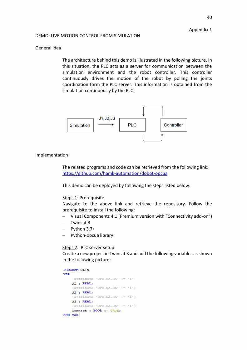
Appendix 1 DEMO: LIVE MOTION CONTROL FROM SIMULATION General idea
The architecture behind this demo is illustrated in the following picture. In this situation, the PLC acts as a server for communication between the simulation environment and the robot controller. This controller continuously drives the motion of the robot by polling the joints coordination form the PLC server. This information is obtained from the simulation continuously by the PLC.
Implementation
The related programs and code can be retrieved from the following link: https://github.com/hamk-automation/dobot-opcua This demo can be deployed by following the steps listed below: Steps 1: Prerequisite Navigate to the above link and retrieve the repository. Follow the prerequisite to install the following:
− Visual Components 4.1 (Premium version with “Connectivity add-on”)
− Twincat 3
− Python 3.7+
− Python-opcua library Steps 2: PLC server setup Create a new project in Twincat 3 and add the following variables as shown in the following picture:

41
Compile and log in to execute the server. Step 3: Simulation start-up Open the “DobotProgram.vcmx” file in Visual Components 4.1+ and navigate to the “Connectivity” tab. On the left hand-side in the “Connectivity Configuration” panel click on the white circle next to “Server” to connect to the PLC server.
(Photo courtesy of Visual Components) After a successful connection, the “Connected Variables” panel at the bottom would display as shown in the following picture when simulation starts.
(Photo courtesy of Visual Components) Step 4: Dobot client start-up The Dobot robot arm must be connected to the user’s device in advance through any USB port. Afterwards, the user can use the relative python command to execute the “livepolling-client.py” file. The program will automatically detect and connect to the robot arm. Step 5: Start the simulation If the above program yields no error, the simulation in Visual Components can be started. The robot will start moving according to the predefined program in the simulation. This program can be edited by navigating to the “Program” tab in Visual Components.