hands-on reconfigurable robotic surgical instrument holder arm · hands-on reconfigurable robotic...
TRANSCRIPT
Hands-on reconfigurable robotic surgical instrument holder arm
Piyamate Wisanuvej, Konrad Leibrandt, Jindong Liu, and Guang-Zhong Yang
Abstract— The use of conventional surgical tool holdersrequires an assistant during positioning and adjustment due tothe lack of weight compensation. In this paper, we introduce arobotic arm system with hands-on control approach. The robotincorporates a force sensor at the end effector which realisestool weight compensation as well as hands-on manipulation.On the operating table, the required workspace can be tightdue to a number of instruments required. There are situationswhere the surgical tool is at the desired location but theholder arm pose is not ideal due to space constraints orobstacles. Although the arm is a non-redundant robot becauseof the limited degrees of freedom, the pseudo-null-space inversekinematics can be used to constrain a particular joint of therobot to a specific angle while the other joints compensate inorder to minimise the tool movement. This allows operatorto adjust the arm configuration conveniently together withthe weight compensation. Experimental results demonstratedthat our robotic arm can maintain the tool position duringreconfiguration significantly more stably than a conventionalone.
I. INTRODUCTION
Many surgical procedures require tools to hold and main-tain instruments or part of the patient body in positionwhile the surgeon performs surgical tasks. In general, theinstrument holders are made in the form of an articulatedarm where one side is mounted to a fixed foundation. Thearm has a control knob or lever to lock the joints in place.Examples of such holder arm include: Martin Arm System(KLS Martin Group, Germany), TEM Instrument SupportArm (Richard Wolf, Germany), Mayfield Head Clamp (Inte-gra LifeSciences, USA). These arms are purely mechanical-based for ease of construction, robustness, and sterilisability.However, due to the lack of weight compensation, theoperator has to carry both the weight of the tool and itspayload which makes it difficult to be manoeuvred safely. Anassistant is usually required when operating the mechanicalholding arms.
Some holder arm systems use electronic locking mech-anism to reduce the time required to release and lock thejoints. Such systems include Point Setter (Mitaka, Japan),EndoTAIX (SurgiTAIX AG, Germany). Although these de-vices are more convenient to use due to instant lock-ing/releasing mechanism, they are still not weight compen-sated. There are several commercial robotic systems for tool
Piyamate Wisanuvej is supported by the Institute of Global Health Inno-vation, Imperial College London and the Faculty of Engineering, KasetsartUniversity. Konrad Leibrandt is supported by the Imperial College PhDScholarship Scheme and EPSRC UK.
All authors are with the Hamlyn Centre for Robotic Surgery,Imperial College London, SW7 2AZ, UK. Piyamate Wisanuvej isalso with Kasetsart University, Bangkok, Thailand. {piyamate.w12,k.leibrandt12, j.liu, g.z.yang}@imperial.ac.uk
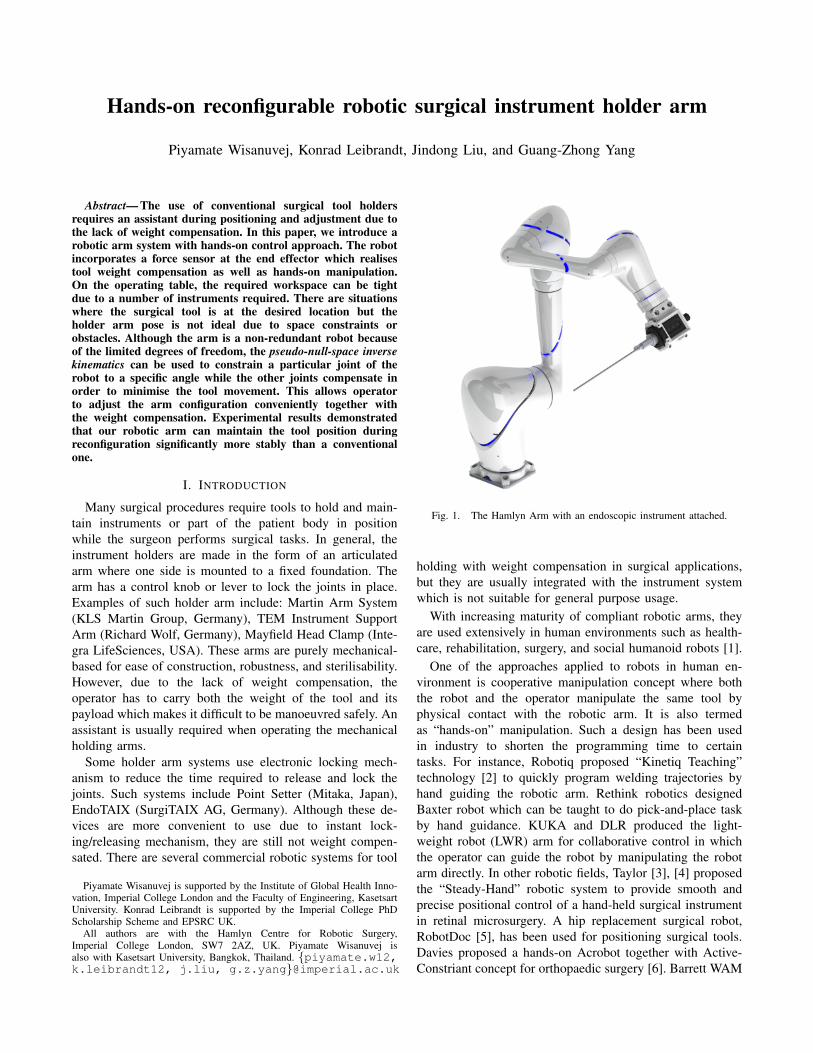
Fig. 1. The Hamlyn Arm with an endoscopic instrument attached.
holding with weight compensation in surgical applications,but they are usually integrated with the instrument systemwhich is not suitable for general purpose usage.
With increasing maturity of compliant robotic arms, theyare used extensively in human environments such as health-care, rehabilitation, surgery, and social humanoid robots [1].
One of the approaches applied to robots in human en-vironment is cooperative manipulation concept where boththe robot and the operator manipulate the same tool byphysical contact with the robotic arm. It is also termedas “hands-on” manipulation. Such a design has been usedin industry to shorten the programming time to certaintasks. For instance, Robotiq proposed “Kinetiq Teaching”technology [2] to quickly program welding trajectories byhand guiding the robotic arm. Rethink robotics designedBaxter robot which can be taught to do pick-and-place taskby hand guidance. KUKA and DLR produced the light-weight robot (LWR) arm for collaborative control in whichthe operator can guide the robot by manipulating the robotarm directly. In other robotic fields, Taylor [3], [4] proposedthe “Steady-Hand” robotic system to provide smooth andprecise positional control of a hand-held surgical instrumentin retinal microsurgery. A hip replacement surgical robot,RobotDoc [5], has been used for positioning surgical tools.Davies proposed a hands-on Acrobot together with Active-Constriant concept for orthopaedic surgery [6]. Barrett WAM
[7] robotic arm has been applied in upper limb strokerehabilitation in which the patient can drag the end effectorof the arm to exercise. DLR also proposed MiroSurge system[8] with hands-on endoscopic instruments control capability.
Robotic arms designed to operate in a complex or dynamicenvironment often have redundant kinematic configurations,i.e. the robot has more degrees of freedom (DOF) thannecessary, in order to avoid obstacles [9], [10], preventoverturns [11], or tolerate joint failures [12], etc. Particularly,7-DOF articulated robot arms have been widely used formanipulating objects in 6-DOF space. One common task forredundant robotic arms is to perform a null-space motionwith one joint being kept stationary, particularly to keep theend effector static while allowing configuration changes tocomply with the surrounding environment. In some situa-tions, however, the number of joints in a robotic arm arelimited to six or lower, such as when joint failure occursor with limited space. It is an impossible job for thesenon-redundant robotic arms to perform the same motionas the redundant arms. Nevertheless, it is feasible to haveredundant-like motion when the position tolerance is loose.
In this paper, we introduce a robotic positioning arm forsurgical instrument holding applications, the Hamlyn Arm,see Fig. 1. This arm addresses common issues found inconventional (purely mechanical) surgical positioning armswhich is the lack of weight compensation. Such compen-sations can make manipulation more convenient and re-quire less effort from the user which is demonstrated inour experiment. In many surgical procedures, there canbe multiple surgical instruments occupying the operatingtable workspace. Occasionally, when the surgical tools arerepositioned to a preferred location, the resulting holder armpose might obstruct the required workspace. In this case,the user has to reposition the holder arm linkages whilekeeping the surgical tool in place, i.e. reconfiguration. Thistask can be demanding, hence it is often done with multipleoperators. To address this issue, we implement a hands-onreconfiguration technique. This enables user to change thearm body while it automatically maintains the mounted toolin place. Although the Hamlyn Arm is not a redundant robot,the pseudo-null space inverse kinematics (Section III-B)allows user to change the joint position while the robot triesto compensate and keep the end effector movement minimal.Another advantage of having robotic holding system is thecapability of sensing of the tool position which enables anintegration with imaging or navigation system.
The remainder of this paper is organised as follows. Thehardware designs and system integration of the HamlynArm are described in Section II. Then, Section III explainsthe methods for hands-on manipulation with weight com-pensation, the pseudo-null space inverse kinematics calcula-tions, and the joint compliant control scheme for hands-onreconfiguration. In Section IV, two experiments involvingparticipants to evaluate our methods are presented. The firstexperiment evaluates the performance of positioning tasksgiven the different tool weights, as well as the workloadrequired by the users. This study compares the performance
of using the holder arm with and without the weight compen-sation. The second experiment demonstrates how the HamlynArm performed compared to a conventional tool holder intargeting and reconfiguration tasks.
II. HAMLYN ARM
The Hamlyn Arm is an articulated robot with six degreesof freedom. It is actuated by brushless DC motors coupledwith harmonic drive gears. On-board controllers performposition, velocity, and current regulation. The arm weights3.0 kg and reaches 770 mm at extended pose. The combi-nation of motors and gears are selected so that the arm canhandle a maximum payload of 1.5 kg with limited speedand acceleration. Each joint can also be backdriven by anoperator in case of power loss.
The robot communicates via CANopen bus with a com-puter system in which we have our control system im-plemented. The high level control software runs on Linuxoperating system. It perform several tasks including: motiongeneration, inverse kinematics, and communication with themotor controllers. Cartesian and joint trajectories generationis done using Reflexxes Motion Libraries [13].
The Hamlyn Arm incorporates an ATI Mini40 force/torquesensor by ATI Industrial Automation (NC, USA) at the endeffector. The data is sampled with a DAQ PCIe card byNational Instrument (TX, USA) running at 32 kHz samplingrate. The measurements are then filtered with a movingaverage filter with 100-sample window size. Fig. 1 showsthe Hamlyn Arm with a mounted endoscopic instrument.
III. METHODS
A. Hands-on positioning with weight compensation
Positioning is one of the most common purpose of roboticmanipulators where users can command the robot end ef-fector to the desired position and orientation. The hands-onapproach allows user to cooperatively guide the robot byhands to the desired location. The robot passively followthe user guidance and holds position when the user releases
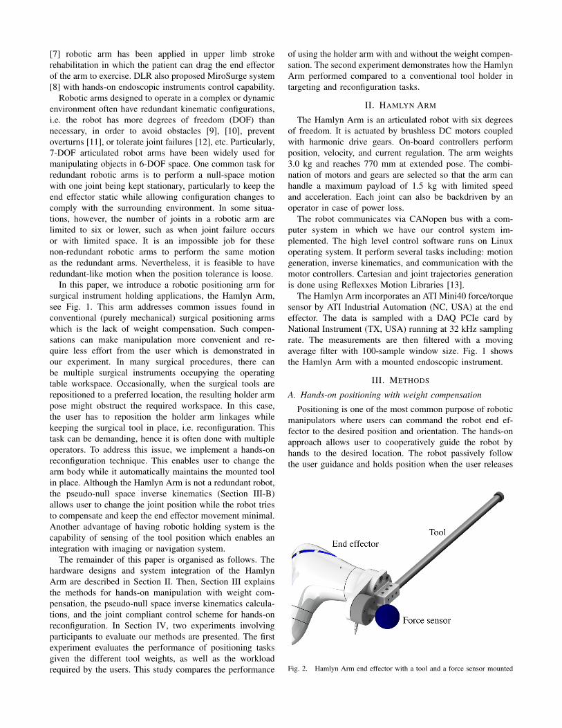
Fig. 2. Hamlyn Arm end effector with a tool and a force sensor mounted
control. To sense external manipulation forces, a force sensoris installed to the end effector. The force sensor is placedsuch that the manipulation force is decoupled from the tool’sweight. An example of such setup is shown in Fig. 2. Thecontrol scheme for hands-on manipulation is implementedby commanding the robotic end effector position accord-ing to the force measurements of the sensor. Due to theplacement of the sensor, tool’s weight and robot’s weightdo not affect the measurements. Therefore, the user perceiveminimal force during manipulation and the tool can maintainposition when released. Moreover, this configuration allowstool exchange without required calibration.
Our implementation is as follows. The raw reading fromthe sensor is subtracted with the baseline force to accountfor sensor’s offset and the weight of the handle. The robotend effector movement is modelled as a virtual mass witha uniform friction in all directions. The force reading F inCartesian space is converted to acceleration A by Newton’sLaw of motion and classical Coulomb friction model [14].Resulting velocity from an integration of A is fed into atrajectory generator. The resulting robot pose is sent to therobot as a position command. The inverse kinematics routinethen converts the Cartesian space into joint space trajectoryfor the motor controllers.
B. Pseudo-null-space inverse kinematics
The standard approach to solve the local inverse kinemat-ics of a redundant robots is to combine the Moore-Penrosepseudoinverse together with a mapping of secondary goalsinto the null space [15]. Whereas, usually the primary goal isto reach a desired end effector pose TTT d , classical secondarygoals include singularity, joint limit, and collision avoidance.Null space mapping allows to use the redundant DoFs tofollow secondary goals without impairing the achievementof primary goals. The pseudoinverse matrix JJJ†, can becalculated as:
JJJ† =VVV diag(
1σ1
, . . . ,1
σn
)UUUT , (1)
where σi are the singular values of JJJ resulting from singularvalue decomposition and UUU ,VVV are the left-singular and right-singular vectors respectively (i.e. JJJ =UUUdiag(σ1, . . . ,σn)VVV T ).JJJ† is further used to calculate the joint velocities of theredundant manipulator;
qqq = JJJ† xxx+(IIIn− JJJ†JJJ
)qqq0 (2)
where IIIn is the n-dimensional identity matrix, and xxx ∈ R6
the desired end effector velocity to reach the pose TTT d . Thesecond summand of (2) is used to map secondary goals qqq0into the null space. qqq0, is defined as:
qqq0 = kω0
(∂ω(qqq)
∂qqq
)T
(3)
where kω0 is a goal weighting factor and ω (q) is theobjective function for the secondary goals.
To overcome the problem of singular robot configurationsthe damped-least-squares (DLS) inverse JJJ? can be used at
the expense of slower convergence in comparison to thepseudoinverse Jacobian JJJ†:
JJJ? =VVV diag(
σ1
σ21 +λ 2 , . . . ,
σn
σ2n +λ 2
)UUUT , (4)
where λ is the damping factor. Finally, the robot end effectorTTT ee pose can be calculated using:
TTT ee = fff FW (qqq+ qqq∆t) , (5)
where fff FW denotes the closed-form forward kinematic func-tion.In order to control an underactuated robot with n-joints(n=5 in our case) the proposed pseudo-null space conceptconsiders task-space primary goals as xxxpri = [tx, ty, tz] andthe remaining three DoFs are considered as secondary goalsxxxsec = [rx,ry,rz]. Therefore, we split the Jacobian JJJ ∈ R6×n
into JJJpri, JJJsec ∈ R3×n with,
JJJ =[JJJT
pri,JJJTsec]T
(6)
as well as the task-space velocities xxx =[xxxT
pri, xxxTsec
]Tand
calculate the DLS-inverse JJJ?pri and JJJ?sec, according to (4).Following,
qqq0 = fk (∆xxxpri) JJJ?sec xxxsec, (7)
the secondary goals can be computed, where fk (∆xxxpri) is ascalar weighting function depending on the deviation fromthe primary goals. Combining (2) with (7) where JJJ?pri isused instead of JJJ† the joint velocities for the underactuatedmanipulator can be calculated. Note that using a DLS-inverseresults in deviations from the primary goals and furthermoreintroduces an error into the null-space mapping. The scalingfunction in (7) is chosen as:
fk = 1−min(‖∆xxxpri‖,∆xpri,max)
∆xpri,max, (8)
where ∆xpri,max denotes a threshold for the maximum devi-ation from the primary goals for which secondary goals areconsidered. For small ∆xpri,max secondary goals are quicklyignored and errors in the null-space mapping introducedby the DLS-inverse are mitigated, a large value in contrastrepresent a looser following of the primary goals.
C. Hands-on manipulator reconfiguration
Hands-on positioning the robot via an external force sensoris one way to command the robot cooperatively. However,relying on this alone would constrain the robot in theconfiguration provided by the inverse kinematics calculation.There are situations where the kinematics solutions are notideal due to space constraints or obstacles. Using the pseudo-null space inverse kinematics can constrain a particular jointof the robot to a specific angle. This can allow the userto change the robot configuration to better suit the spacerequirements. However, changing this null-space constrainvia computer interface might interrupt the user’s workflowwhen performing tasks. Hence, we introduce another hands-on manipulation mode where user can directly reconfigure

the robot by pushing its linkages. This is complementary tothe hands-on positioning and can be used together to performmanipulation tasks more intuitively.
To implement compliant control on joints, an externaljoint torque measurement is required. For simplification, ourimplementation uses motor current measurements providedby the joint controllers. This is a crude measurement whichdoes not take into account the transmission loss and friction.A thresholding on the measured current is used to determinewhether a joint is pushed by the user. This threshold is tunedmanually to suit a certain range of velocity and accelerationsettings. Since the method is oversimplified and inaccurate,the joint output velocity is smoothen by a trajectory generatorbefore being sent to the kinematics calculation.
IV. EXPERIMENTS AND RESULTS
A. Hands-on positioning study
An experiment is setup to evaluate hands-on positioningperformance on a commercially available robot designed forthis purpose using its built-in gravity and payload compen-sation in comparison to our approach described in sectionIII-A.
The Lightweight Robot 4+ (LWR4+) by KUKA RoboterGmbH (Augsburg, Germany) is chosen due to its built-in gravity compensation mode. This compensation is donevia precise robot modelling and friction compensation bythe joint torque sensors. Still, this requires correct payloadparameters in order to compensate correctly. In the sametime, we can easily equip a force sensor to the end effectorand switch the robot operation to position control mode toemulate the Hamlyn Arm. Therefore, it allows experimentingwith the same robot hardware for both configurations.
The setup is illustrated in Fig. 3, which consists of aLWR robot and a Mini40 Force/Torque Sensor. AnotherLightweight Robot iiwa 14 R820 is used to hold the tube
Fig. 3. System components: A) KUKA LWR4+, B) KUKA LBR iiwa,C) ATI Mini40, D) Tool, E) Tube, F) Adjustable weights
for the experiments. Dummy tool with variable weights ismounted on the tool to mimic different tool weights.
A tool insertion task is used to validate the hands-onmanipulation method. The task for each participant is to pick-up and move the tool tip from a starting point far from thetube to the entry point of the tube by holding only the knobwith one hand. The tool should be guided along the centrelineof the tube until the tooltip reaches the exit point. Participantsare asked to perform the task three times, with different toolweights and compensation modes between tasks.
The light and heavy tool are weighted 0.8 kg and 1.4kg respectively. The compensation methods used are theLWR’s built-in gravity compensation and our external forcesensor based method. Therefore, there are four variations ofparameters for this experiment in total. They are denoted asLWR−Light, LWR−Heavy, FT −Light, and FT −Heavy.The task is repeated three times for each participant.
In order to evaluate the effects of manipulating an un-calibrated tool, the LWR has only the correct tool parametersfor the light tool. Hence, the user is expected to perceive 0.6kg of equivalent tool weight with LWR−Heavy manipulationtask.
Each participant is given 10 minutes to get familiar withthe system in all task variations. There are total of 5participants who took part in the experiments, resulting in 60recorded tasks. Only the manipulation within the tube regionis analysed while the rest is discarded. Three performancemetrics for each are calculated: completion time, positiondeviation from the tube centreline, and manipulation force.
B. Hands-on positioning – Results
Comparison of results from all four tasks with time, force,and position metrics are shown in Table I. We observedonly small difference between methods in terms of taskcompletion time, ranging from 4.33 to 5.5 seconds, withLWR− Light being the fastest. Also, it is observed thatall the tasks have similar positional deviation, with the FT-tasks having slightly smaller deviation. However, there is asignificant difference in manipulation force between LWRand FT methods. The force required to move the tool isalways under 1.5 N for the FT methods, while LWR’s gravitycompensation method requires around 7 N with calibratedtool and 12 N with un-calibrated tool as depicted in Fig. 4.
TABLE IRESULTS FROM HANDS-ON POSITIONING EXPERIMENT SHOWING
MEAN±SD AND (MIN−MAX)
LWR-Light LWR-Heavy FT-Light FT-HeavyTime 4.33±1.94 5.30±3.06 5.50±2.20 4.64±1.14
(s) (2.67−9.47) (2.25−12.54) (2.89−8.46) (3.59−7.33)Deviation 3.89±1.84 3.83±1.90 3.39±1.41 2.35±1.31
(mm) (0.14−9.27) (0.06−9.63) (0.57−9.11) (0.15−7.97)Force 7.32±0.91 11.98±1.53 1.36±0.25 1.46±0.23
(N) (3.88−11.66) (6.20−15.28) (0.44−2.56) (0.49−2.20)

LWR-Light LWR-Heavy FT-Light FT-Heavy
0
2
4
6
8
10
12
14
16
Man
ipula
tion F
orc
e (N
)
Fig. 4. Comparison of user manipulation force
Fig. 5. Experiment setup for targeting and reconfiguration tasks
C. Hands-on reconfiguration study
We setup a comparative study to evaluate the benefit ofusing the compensated robotic tool holder in contrast tomanually operated operating table arms when the workspaceis limited and a reconfiguration is required. The task chosenis a targeting task where the user is asked to move a longdummy surgical tool from an initial position to three differenttargets. After reaching the target, the user has to reconfigurethe arm base joint to a specific angle in order to keep theworkspace around the base joint clear while maintaining thetool position. The experiment setup is shown in Fig. 5.
Tasks are performed using the Hamlyn Arm working intwo different modes. A manual mode, where the arm canbe locked and released with a foot pedal, emulates the
5 10 15 20 25 30 35 40-100
-50
0
50
Bas
e Jo
int
(deg
)
5 10 15 20 25 30 35 400
100
200
300
Tool
Posi
tion (
mm
)
5 10 15 20 25 30 35 40
Time (s)
0
100
200
Tar
get
(m
m)
(a) manual mode
5 10 15 20 25 30 35-100
-50
0
50
Bas
e Jo
int
(deg
)
5 10 15 20 25 30 350
100
200
300T
ool
Posi
tion (
mm
)
5 10 15 20 25 30 35
Time (s)
0
100
200
Tar
get
(m
m)
(b) compensated mode
Fig. 6. Examples of collected data from experimental tasks with differentoperation modes.
functionality of a conventional surgical instrument holderarm. A compensated mode, where the arm exhibits hands-on positioning and reconfiguration capabilities. All recon-figurations requires the base joint to be moved more than90◦. For each participant, the experiment is done twicewith tool weights of 0.8 kg and 1.4 kg respectively. Fig. 6shows examples of collected data where the target positionis reached approximately within 8 seconds. Then, the robotis reconfigured. In the compensated case, the robot move-ment appears smoother and less deviated from the target.Additionally, in the manual mode, a fast drop of the toolposition is observed in Fig. 6a at approximately t=4 secondswhen the user pressed the release button (red=X, green=Y,blue=Z). This is due to the lack of gravity compensation.Similarly to the previous experiment, each participant isgiven a certain time to learn the system before the actualtask. There are 5 participants who performed the experiment.In summary, there are 2 operation modes, 3 targets, 2 toolweights. Therefore, 60 tasks were performed in total.
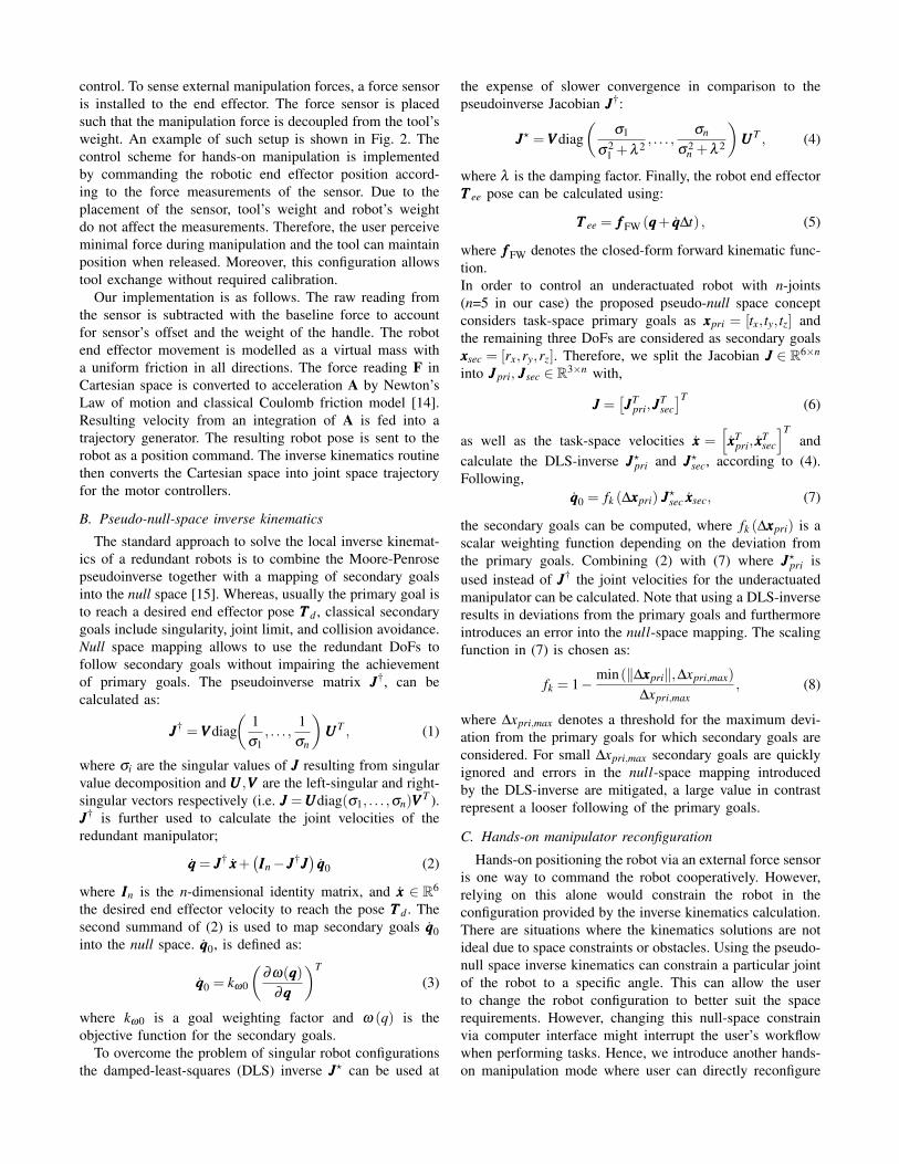
TABLE IIRESULTS FROM HANDS-ON RECONFIGURATION EXPERIMENT SHOWING
MEAN±SD AND (MIN−MAX)
Manual CompensatedTime 21.3±10.5 21.2±4.8
(s) (5.7−45.2) (13.0−31.7)Maximum 83.8±99.1 16.0±7.6
displacement (mm) (16.4−394) (0−32.8)Total movement 805±406 46.4±26.7
(mm) (240−1900) (0−118)
Manual Compensated
0
50
100
150
Max
dis
pla
cem
ent
(mm
)
(a) maximum target displacement
Manual Compensated
0
200
400
600
800
1000
1200
1400
1600
1800
2000
To
tal
dis
tan
ce m
ov
ed (
mm
)
(b) total distance moved
Fig. 7. Results from reconfiguration experiments
D. Hands-on reconfiguration – Results
The metrics used to evaluate the performance are: the timeused to perform reconfiguration, the maximum displacementfrom the target during reconfiguration, and the total distancemoved during reconfiguration. The quantitative results arelisted in Table II. We observed very similar results in thetime required which is around 21 seconds. However, thedisplacement and movement are significantly lower in thecompensated mode. The mean of maximum displacement isdecreased more than 5 times and the mean of total movementis decreased 17 times with the compensation. Fig. 7 showsthe performance improvement of the compensated mode.
V. CONCLUSIONS
In this paper, we have presented the Hamlyn Arm, arobotic holder arm system that allows hands-on manipulationand reconfiguration based on a tool-mounted force sensorand joint current sensors. The arm is targeted at surgicalinstrument holding applications where mechanical articulatedarms are generally used. Our experimental results show theadvantage of using this arm where the weight compensationcan reduce the workload of the operator. The placement ofthe sensor decouples the tool weight from the measurement.Therefore, it allows tool changes during the operation with-out calibration.
In several surgical procedures, multiple surgical instru-ments occupy the workspace around the operating table. An-other advantage of our system is that the user can reconfigurethe holder arm linkages while maintaining the position of
the surgical tool. The pseudo-null-space inverse kinematicsallows the Hamlyn Arm, which is non-redundant, to performa reconfiguration while minimising the tool movement withthe aid of current sensing-based joint compliant control. Ourexperiment shows that performing reconfiguration with apurely mechanical holding arm is a difficult task. With ourmethod in the Hamlyn Arm, the amount of tool movement issignificantly decreased. In the surgical context, it potentiallyleads to less damage to the surrounding anatomy.
ACKNOWLEDGEMENT
The authors would like to thank Petros Giataganas for theCAD renderings and ideas regarding the experiments.
REFERENCES
[1] M. Hvilshøj, S. Bøgh, O. Skov Nielsen, and O. Madsen, “Autonomousindustrial mobile manipulation (AIMM): past, present and future,”Industrial Robot: An International Journal, vol. 39, no. 2, pp. 120–135, 2012.
[2] N. Lauzier et al., “Force/torque sensor, apparatus and method for robotteaching and operation,” US Patent 20 150 323 398, 2015.
[3] R. Taylor et al., “A steady-hand robotic system for microsurgical aug-mentation,” The International Journal of Robotics Research, vol. 18,no. 12, pp. 1201–1210, 1999.
[4] B. Mitchell et al., “Development and application of a new steady-hand manipulator for retinal surgery,” in Proceedings 2007 IEEEInternational Conference on Robotics and Automation. IEEE, 2007,pp. 623–629.
[5] W. L. Bargar, A. Bauer, and M. Borner, “Primary and RevisionTotal Hip Replacement Using the Robodoc (R) System.” Clinicalorthopaedics and related research, vol. 354, pp. 82–91, 1998.
[6] B. Davies et al., “Active-constraint robotics for surgery,” Proceedingsof the IEEE, vol. 94, no. 9, pp. 1696–1703, 2006.
[7] G. Xu, A. Song, and H. Li, “Control system design for an upper-limb rehabilitation robot,” Advanced Robotics, vol. 25, no. 1-2, pp.229–251, 2011.
[8] R. Konietschke et al., “The DLR MiroSurge-A robotic system forsurgery.” in Robotics and Automation, 2009. ICRA ’09. IEEE Inter-national Conference on, vol. 9. IEEE, 2009, pp. 1589–1590.
[9] O. Brock, O. Khatib, and S. Viji, “Task-consistent obstacle avoid-ance and motion behavior for mobile manipulation,” in Roboticsand Automation, 2002. Proceedings. ICRA ’02. IEEE InternationalConference on, vol. 1. IEEE, 2002, pp. 388–393.
[10] M. Duguleana, F. G. Barbuceanu, A. Teirelbar, and G. Mogan,“Obstacle avoidance of redundant manipulators using neural networksbased reinforcement learning,” Robotics and Computer-IntegratedManufacturing, vol. 28, no. 2, pp. 132–146, 2012.
[11] Y. Li and Y. Liu, “A new task-consistent overturn prevention algo-rithm for redundant mobile modular manipulators,” in 2005 IEEE/RSJInternational Conference on Intelligent Robots and Systems. IEEE,2005, pp. 418–423.
[12] J. D. English, A. Maciejewski, and Others, “Fault tolerance for kine-matically redundant manipulators: Anticipating free-swinging jointfailures,” Robotics and Automation, IEEE Transactions on, vol. 14,no. 4, pp. 566–575, 1998.
[13] T. Kroger, “Opening the door to new sensor-based robot applications-The Reflexxes Motion Libraries,” in Robotics and Automation (ICRA),2011 IEEE International Conference on. IEEE, 2011, pp. 1–4.
[14] H. Olsson, K. Astrom, C. Canudas de Wit, M. Gafvert, and P. Lischin-sky, “Friction Models and Friction Compensation,” European Journalof Control, vol. 4, no. 3, pp. 176–195, 1998.
[15] B. Siciliano, L. Sciavicco, L. Villani, and G. Oriolo, Robotics: mod-elling, planning and control. Springer Science & Business Media,2010.