robomow service manual
DESCRIPTION
Robomow Service ManualTRANSCRIPT
Robomower® Service Guide Read carefully and thoroughly all relevant sections before servicing Robomower. It is very important to read and follow all warning and safety instructions in this
manual and in the Robomower Operating Manual. All maintenance procedures and troubleshooting must be carried out exactly as
given in this manual.
All rights reserved. No part of this book may be reproduced or used in any form or by any means – graphic, electronic or mechanical, including photocopying, recording, taping or by any electronic information storage and retrieval systems without a prior written consent of F. Robotics Acquisitions Ltd.
This book was carefully prepared. However, F. Robotics Acquisitions Ltd. will
not bear any responsibility for any errors, mistakes or misunderstandings. F. Robotics Acquisitions Ltd. shall not bear responsibility for any damage resulting from faulty instructions in this manual.
F. Robotics Acquisitions Ltd. reserves the right to introduce changes in the
product and/or to this manual without any prior notice. © 2006. All rights reserved to F. Robotics Acquisitions Ltd.
I
Table of contents Introduction Chapter 1- Robomower Layout & IPL’s (Illustrated Parts List) Chapter 2 - Menu Items Chapter 3 - Troubleshooting Chapter 4 - Repair and Maintenance Procedures Chapter 5 - Diagnostics Chapter 6 – General Procedures Chapter 7 - Service Bulletins
II
Introduction
The purpose of this Service Guide is to allow trained and certified technicians to
efficiently inspect, diagnose and repair the Robomower. If you have not completed training, please contact your manager or supervisor to arrange training completion.
The Service Guide is divided into various sections to allow access to information in an
easy to use format. The sections in the beginning show the layout, wiring, parts and construction of the Robomower. Mid sections show diagnostic techniques and the last sections show repair and warranty procedures.
IMPORTANT: it is the policy of F. Robotics Acquisitions Ltd. that all agents, either
directly appointed or appointed by a distributor, should always show a duty of care to customers. In most countries this is a legal requirement and. F. Robotics Acquisitions Ltd. policy is to always meet these standards and to surpass them wherever possible.
All units inspected by a technician MUST, as a minimum standard, pass the General
Test prior to return to the customer. Units which were actually repaired or had a certain part replaced, must go through
specific testing, of that system, in line with the procedures set out in this Service Guide. The last part of each procedure has the appropriate test for that system.
In addition to testing a specific system or part, a General Test should always be
undertaken to ensure no hidden problems are missed and, most importantly, to ensure that all safety systems are functioning.
If any doubt exists about diagnosis, repair, testing or any other technical aspect of the
Robomower, always be sure to seek further advice from a qualified source.
Finally, if you have any suggestions for improvement of this guide, either in content, layout or additional material, please contact F. Robotics Acquisitions Ltd. through the correct channels and this will be considered for future updates.
III
1. Robomow Layout & Spare Parts
This first section is dedicated to the layout of the Robomow, how it is
constructed, part numbers and identification of parts. Important: Be sure to review section 1.1 (Orientation). It explains what is referred
to as “right”, “left” etc. Failure to understand this can result in a mistake or problem in the analysis or repair of the product.
Table of Contents 1.1 Robomow layout and main components………………2
1.2 IPL’s (Illustrated Parts List) ……………………….….6
1.3 Fuse location…….…………………………….………..19
1.4 Board identification ……………………………………20
1.5 Wiring Layout…….…………………………………….22
1.6 Parts List…….…………………………..………………24
1.7 Parts Compatibility Table…….…………..……………30
1
1
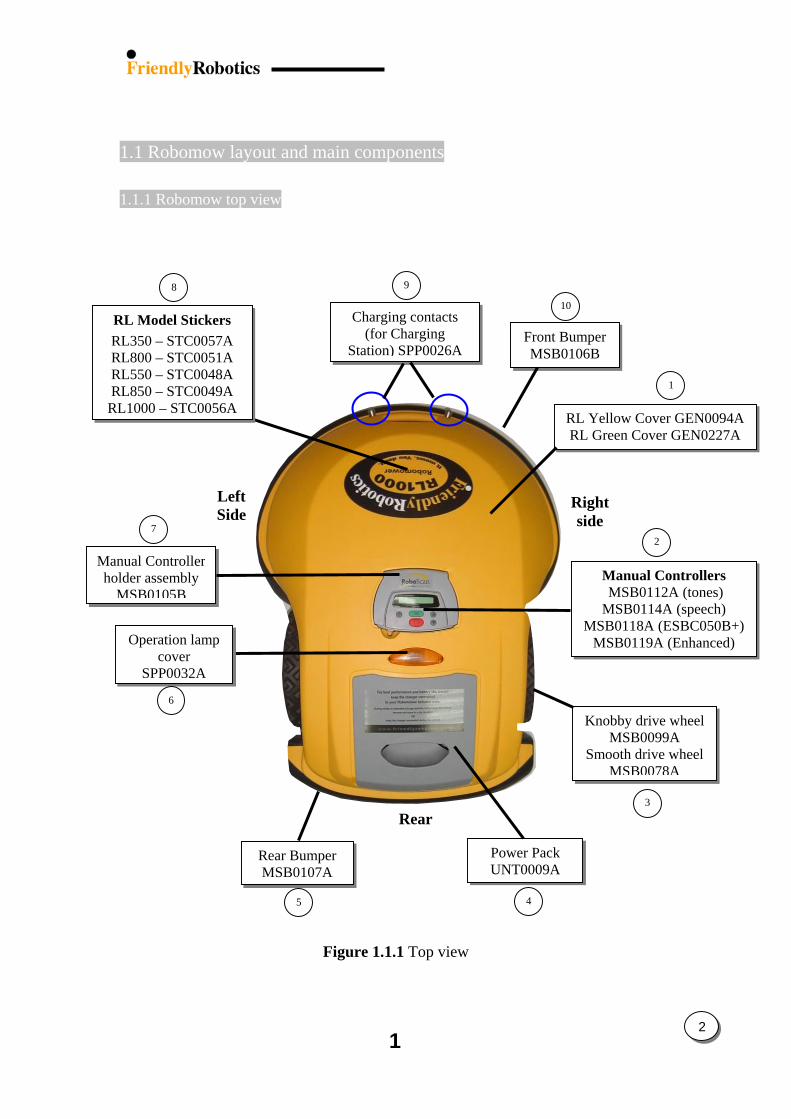
1.1 Robomow layout and main components
1.1.1 Robomow top view
8 9
10
Front Bumper MSB0106B
7
6
5
Fig
Charging contacts (for Charging
Station) SPP0026A
Manual Controllers MSB0112A (tones) MSB0114A (speech)
MSB0118A (ESBC050B+)MSB0119A (Enhanced)
1
RL Yellow Cover GEN0094ARL Green Cover GEN0227A
Right side
2
4
Rear
ure 1.1.1 Top view
1
Knobby drive wheel MSB0099A
Smooth drive wheel MSB0078A
Manual Controller holder assembly
MSB0105B
Operation lampcover
SPP0032A
2
3
Left Side
RL Model Stickers RL350 – STC0057A RL800 – STC0051A RL550 – STC0048A RL850 – STC0049A
RL1000 – STC0056A
Power Pack UNT0009A
Rear Bumper MSB0107A
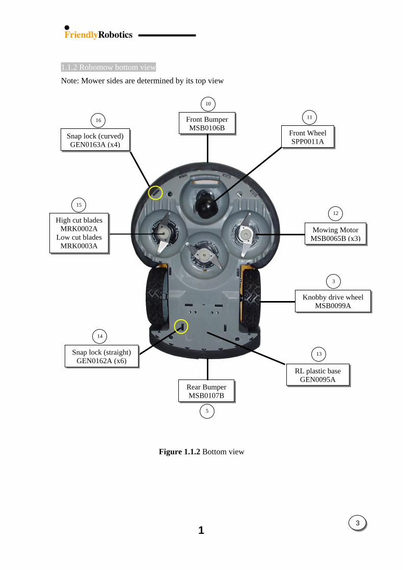
1.1.2 Robomow bottom view
Note: Mower sides are determined by its top view
16
Snap lock (curved)GEN0163A (x4)
Snap lock (straight) GEN0162A (x6)
11
Front Wheel SPP0011A
Front BumperMSB0106B
12
Mowing MotorMSB0065B (x3)
15
High cut blades MRK0002A
Low cut blades MRK0003A
14
5
Rear BumperMSB0107B
3
Knobby drive wheelMSB0099A
13
10
RL plastic base GEN0095A
Figure 1.1.2 Bottom view
1
3
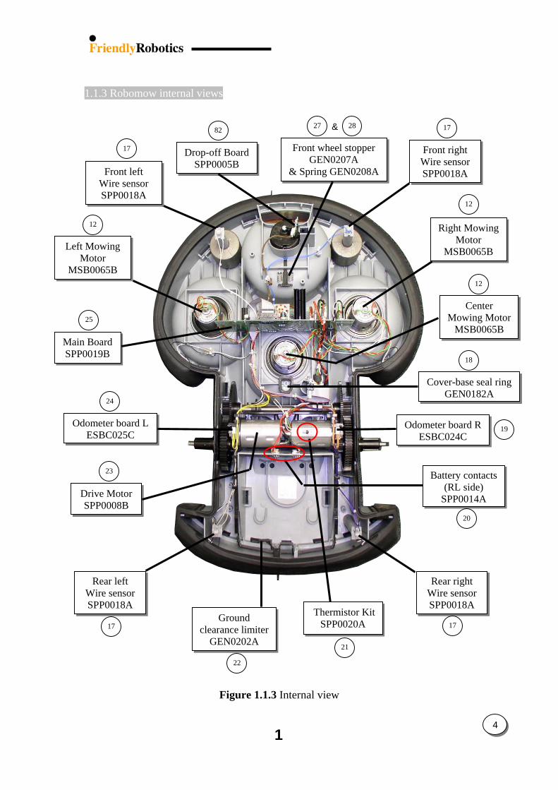
1.1.3 Robomow internal views
Thermistor KitSPP0020A
W
cleaG
Front wheel stopper GEN0207A
& Spring GEN0208A
17
21
22
27 28 1782
12
23
24
25
17
Figure 1.1.3 Internal view
1
Front right Wire sensorSPP0018A
12
Right Mowing Motor
MSB0065B
Front left Wire sensor SPP0018A
MoM
12
18
19
Drive Motor SPP0008B
20
Rear right Wire sensorSPP0018A
Rear left ire sensor
SPP0018A
Cover-base seal ringGEN0182A
17
Ground rance limiterEN0202AMain Board SPP0019B
Drop-off BoardSPP0005B
Battery contacts (RL side)
SPP0014A
Odometer board RESBC024C
Center wing MotorSB0065B
Odometer board L ESBC025C
&
Left MowingMotor
MSB0065B
4
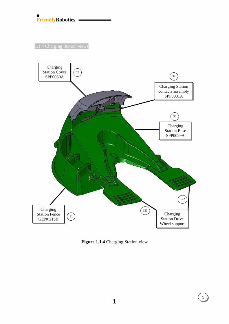
1.1.4 Charging Station views
32
Charging Station Cover
SPP0030A 29
123
Charging Station Fence GEN0215B
31
Figure 1.1.4 Charging Station view
1
Charging Station contacts assembly
SPP0031A
5
30
Charging Station Base SPP0029A
Charging Station Drive
Wheel support
122
1.2 IPL’s / Exploded views
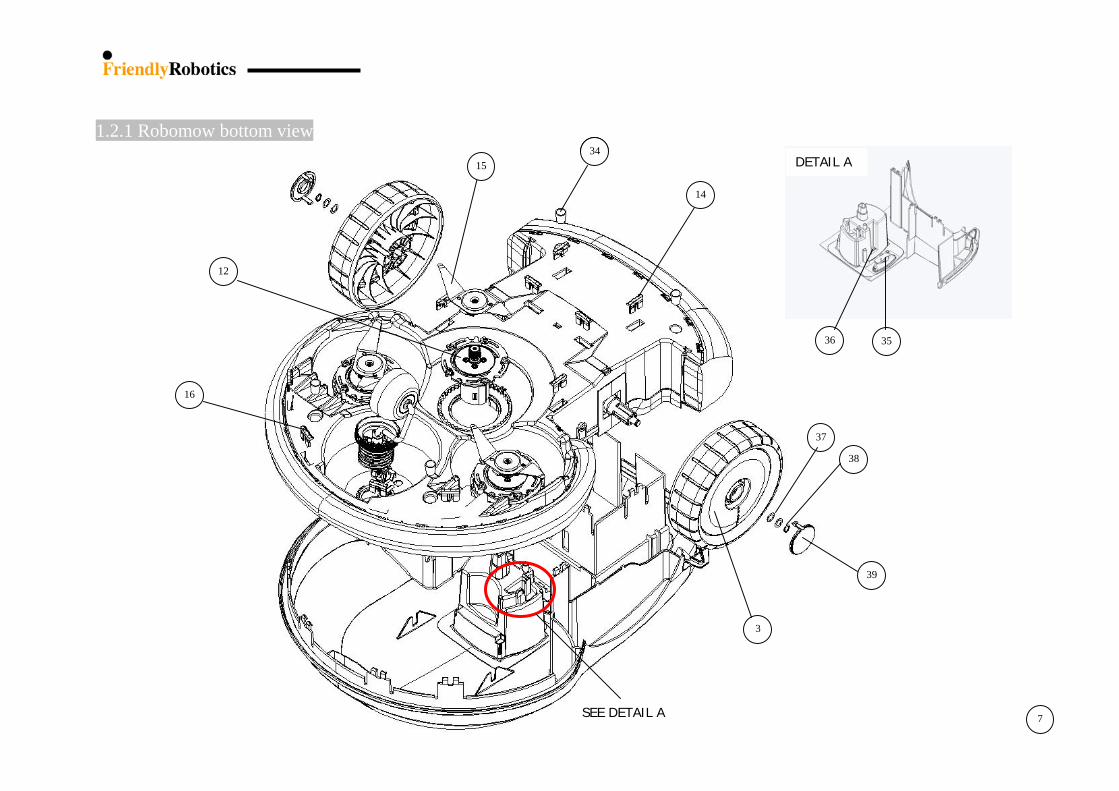
1.2.1 Robomow – bottom view……………………..…7
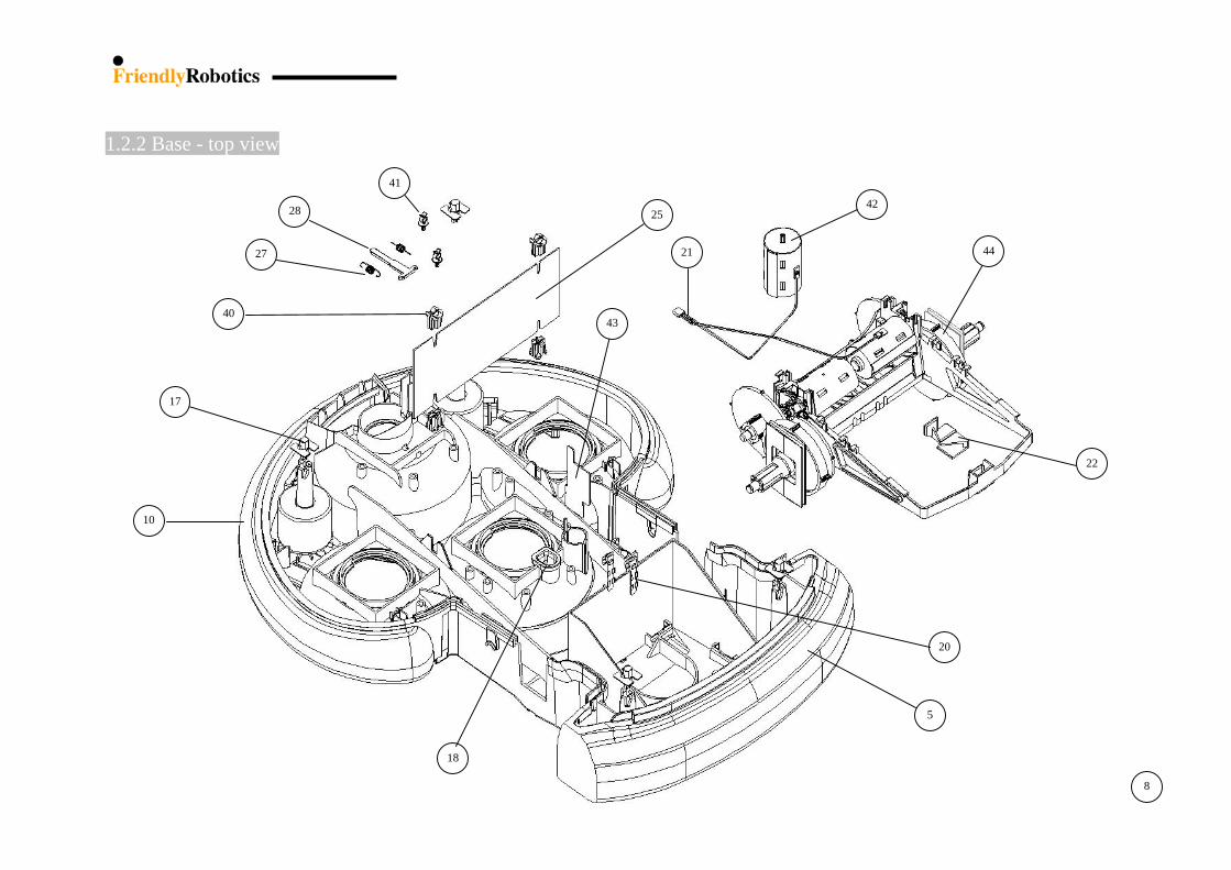
1.2.2 Base – top view.…………………………………8
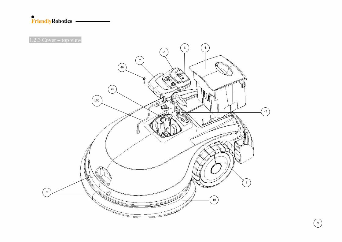
1.2.3 Cover – top view…….……………………….….9
1.2.4 Charging Station…….……………………..…..10
1.2.5 Gear Case ……………………………………...11
1.2.6 Power Pack & Power Supply………………….12
1.2.7 Fuses.....................................................................13
1.2.8 Perimeter Switch…….…………………………14
1.2.9 Bumpers………………………………………...14
1.2.10 Front Wheel…….……………………………..15
1.2.11 Thermistors…….……………………………...16
1.2.12 Add-on Items…….…………………………….16
1.2.13 Decals…….…………………………………….17
1.2.14 Old configuration spare parts………………..18
1
6
1
1.2.1 Robomow bottom view
7
DETAIL A
34
3536
12
16
14
SEE DETAIL A
39
37
38
3
34DETAIL A 15
7
1
8
1.2.2 Base - top view
41 4228 25
442127
4043
17
22
10
5
18
20
8
1 9
1.2.3 Cover – top view
45
3
46
24
105
7
10
9
6
47
9
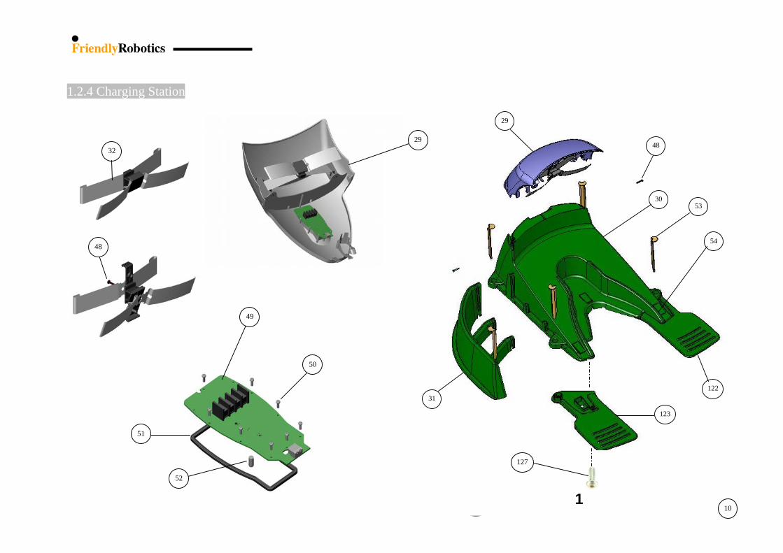
1.2.4 Charging Station
10
53 30
48
29
31
54
122
123
29 32
48
49
50
127
51
52
1 10
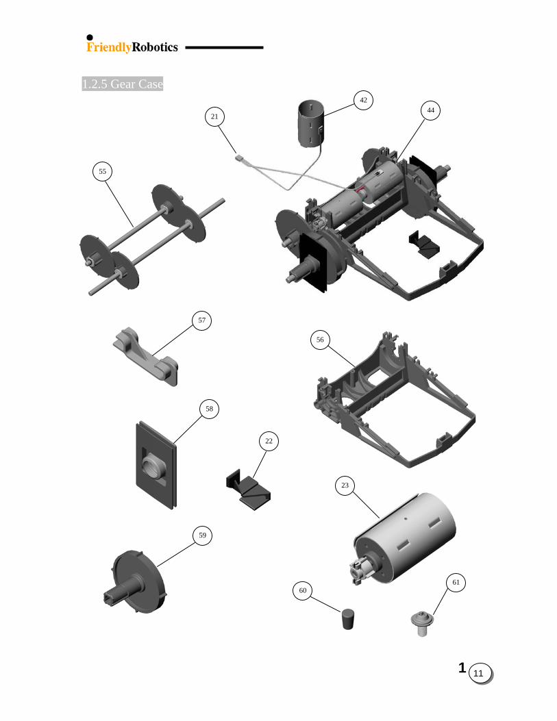
1.2.5 Gear Case
55
42
2144
57
56
58
22
23
59
61
60
1
11
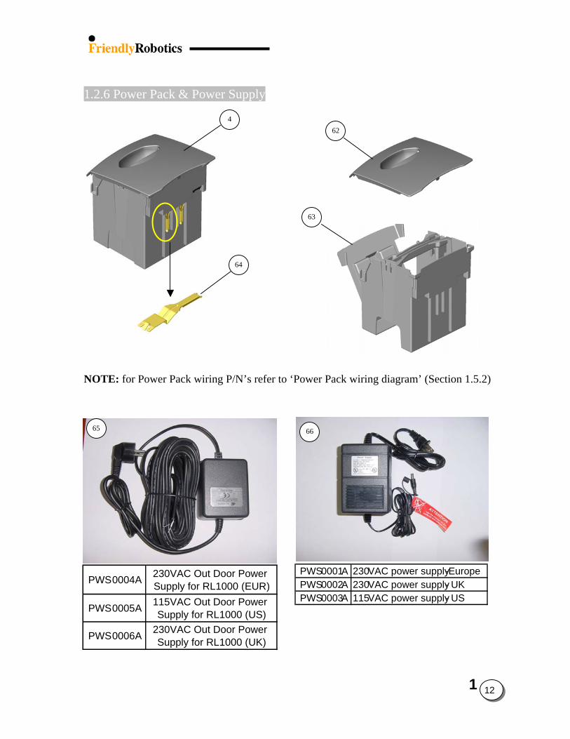
1.2.6 Power Pack & Power Supply
4 62
63
64
NOTE: for Power Pack wiring P/N’s refer to ‘Power Pack wiring diagram’ (Section 1.5.2)
65 66
PWS0001A 230VAC power supply -Europe PWS0002A 230VAC power supply - UKPWS0003A 115VAC power supply - US
PWS0004A 230VAC Out Door Power Supply for RL1000 (EUR)
PWS0005A 115VAC Out Door Power Supply for RL1000 (US)
0006A 230VAC Out Door Power Supply for RL1000 (UK)PWS
1
12
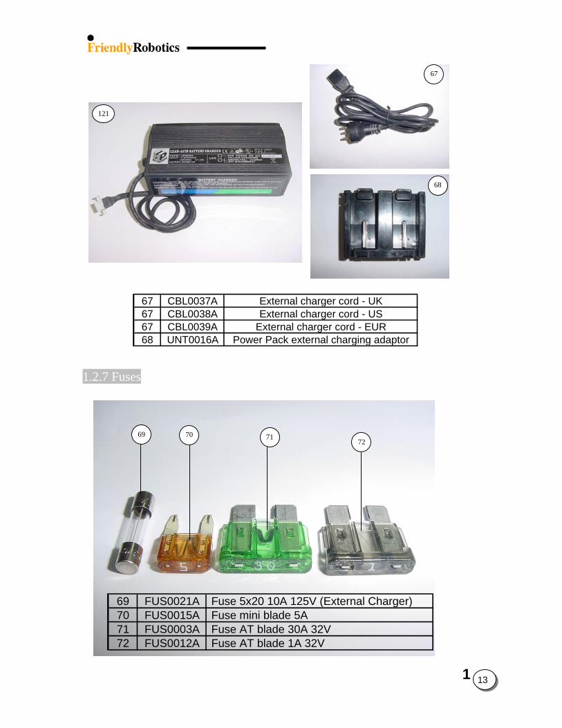
67
121
68
67 CBL0037A External charger cord - UK67 CBL0038A External charger cord - US67 CBL0039A External charger cord - EUR68 UNT0016A Power Pack external charging adaptor
1.2.7 Fuses
69 70 71
72
69 FUS0021A Fuse 5x20 10A 125V (External Charger)70 FUS0015A Fuse mini blade 5A 71 FUS0003A Fuse AT blade 30A 32V72 FUS0012A Fuse AT blade 1A 32V
1
13
1
14
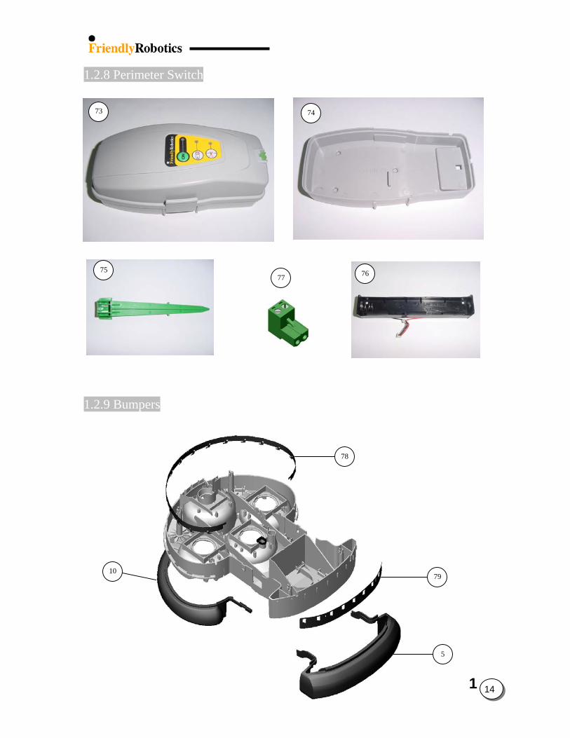
1.2.8 Perimeter Switch
73 74
75 7677
1.2.9 Bumpers
78
1079
5
15
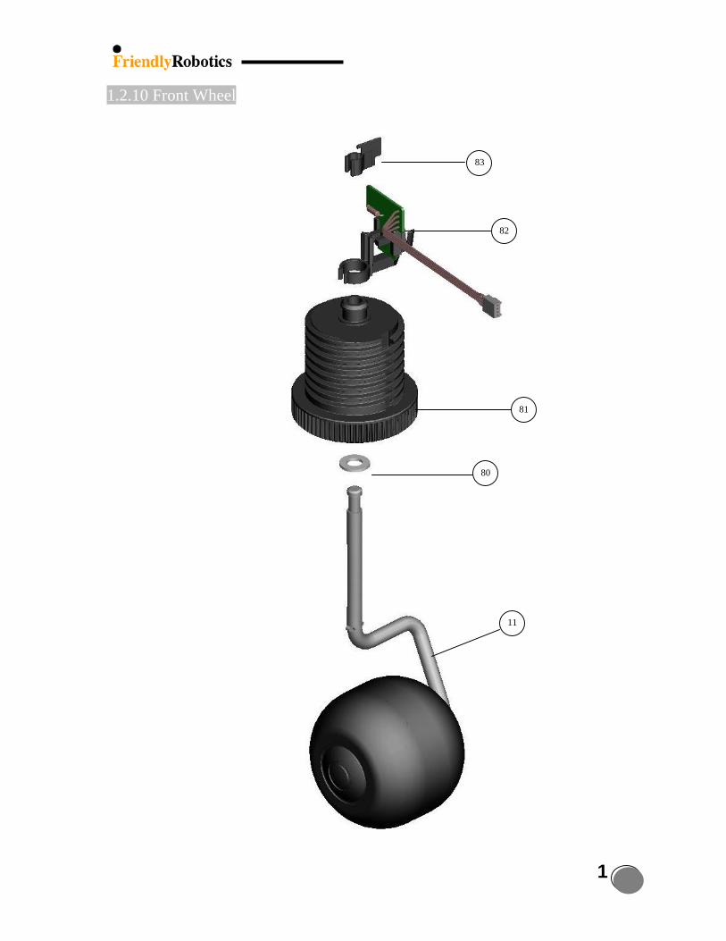
1.2.10 Front Wheel
83
82
81
80
11
1
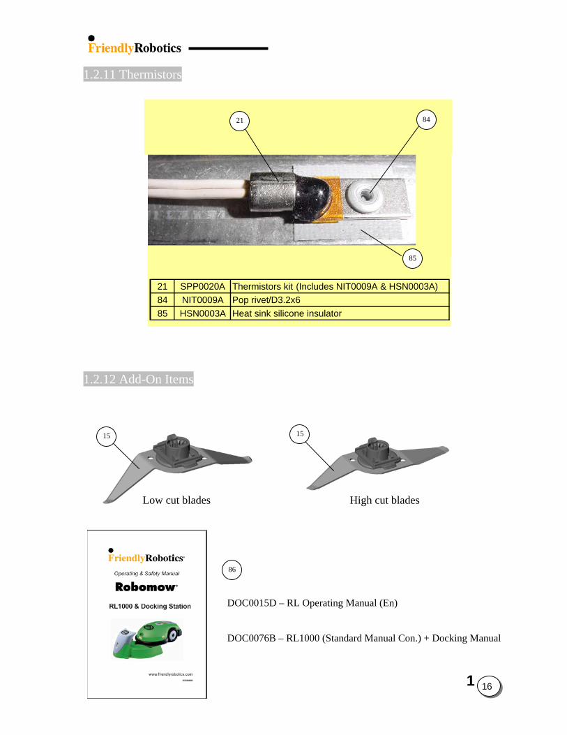
1.2.11 Thermistors
8421
85
21 SPP0020A Thermistors kit (Includes NIT0009A & HSN0003A)84 NIT0009A Pop rivet/D3.2x685 HSN0003A Heat sink silicone insulator
1.2.12 Add-On Items
1515
Low cut blades High cut blades
86
DOC0015D – RL Operating Manual (En)
DOC0076B – RL1000 (Standard Manual Con.) + Docking Manual
1
16
1
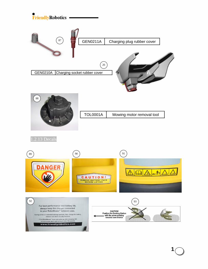
GEN0211A Charging plug rubber cover87
26
GEN0210A Charging socket rubber cover
88
TOL0001A Mowing motor removal tool
1.2.13 Decals
9190
89
17
92 93
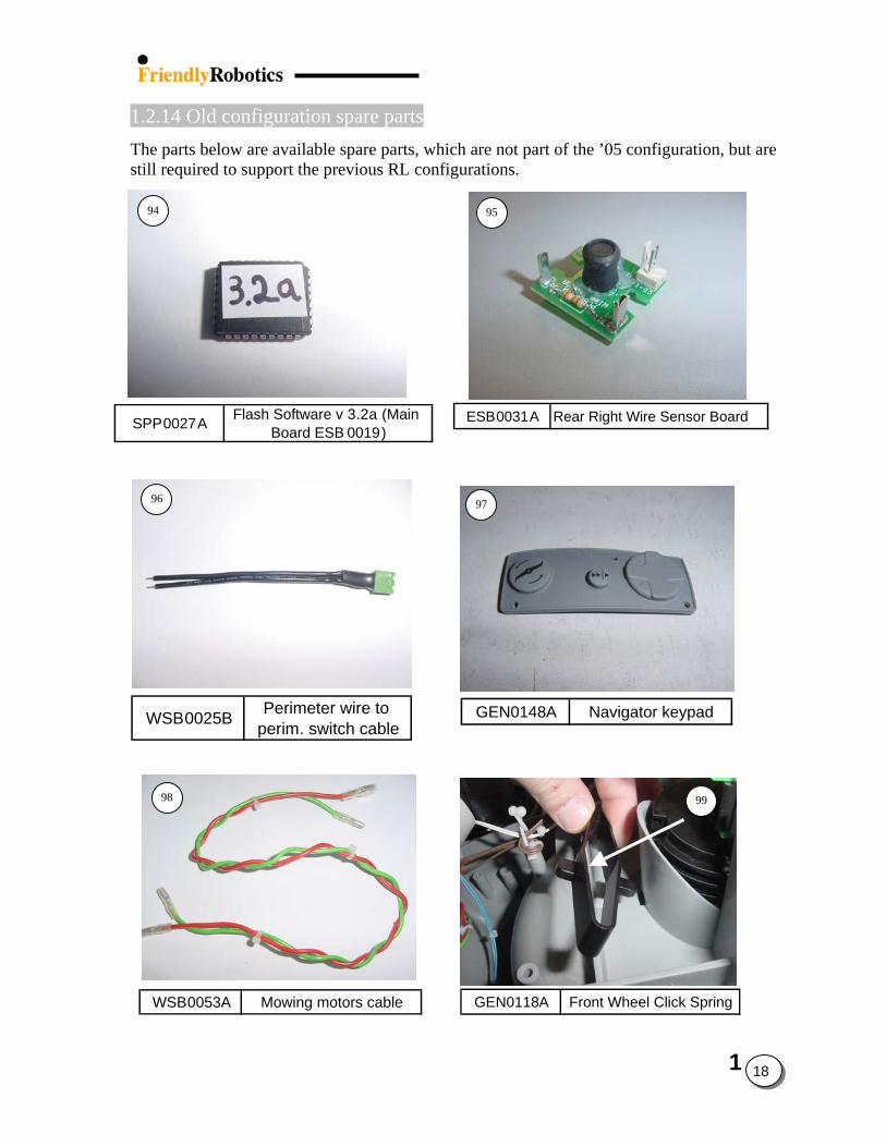
1.2.14 Old configuration spare parts The parts below are available spare parts, which are not part of the ’05 configuration, but are still required to support the previous RL configurations.
ESB0031A Rear Right Wire Sensor Board
GEN0148A Navigator keypad
GEN0118A Front Wheel Click SpringWSB0053A Mowing motors cable
WSB0025B Perimeter wire to perim. switch cable
SPP0027A Flash Software v 3.2a (Main Board ESB 0019)
94 95
96 97
98 99
1
18
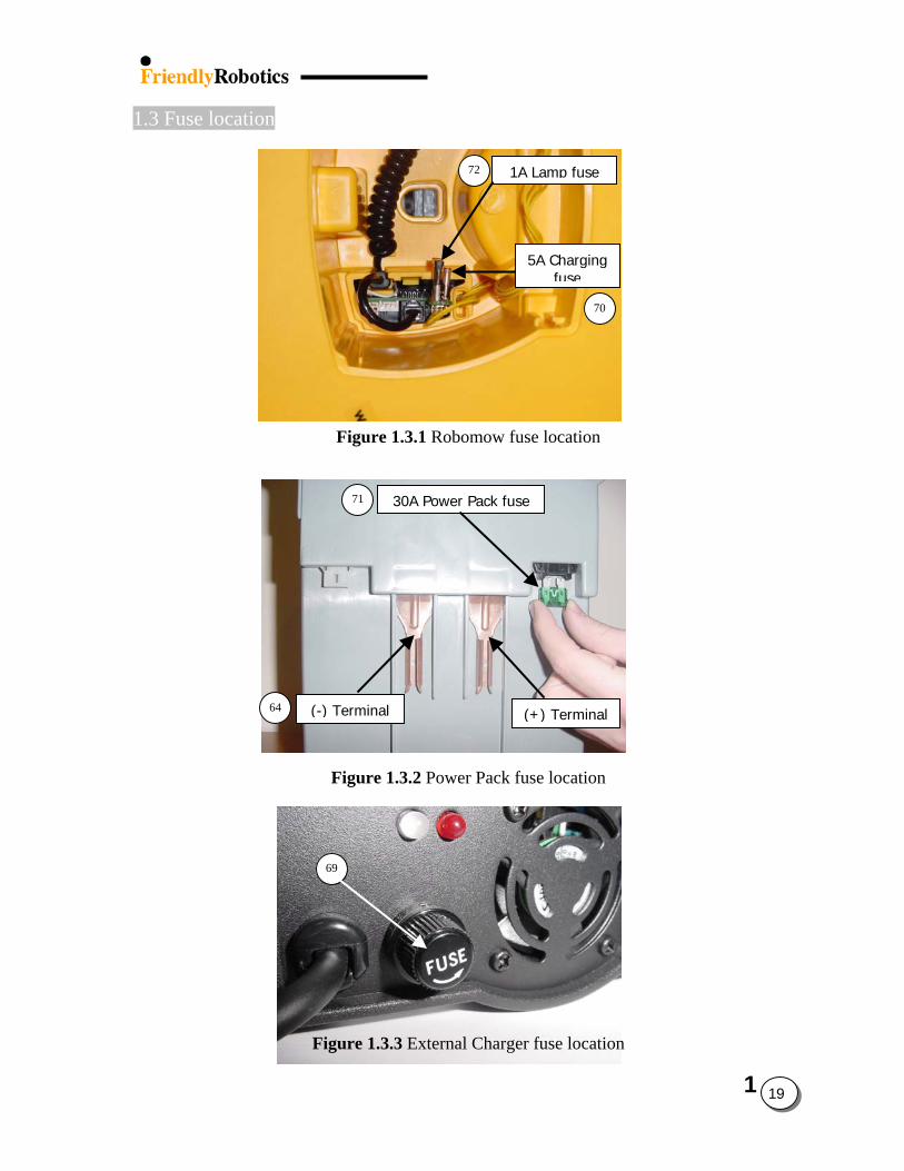
1.3 Fuse location 72
Figure 1.3.1 Robomow
71
l
64
Figure 1.3.2 Power Pac
69
Figure 1.3.3 External Cha
1A Lamp fuse
fu
k f
rge
5A Chargingfuse
70
se location
l
(-) Termina (+) Termina30A Power Pack fuse
use location
r fuse location
1
19
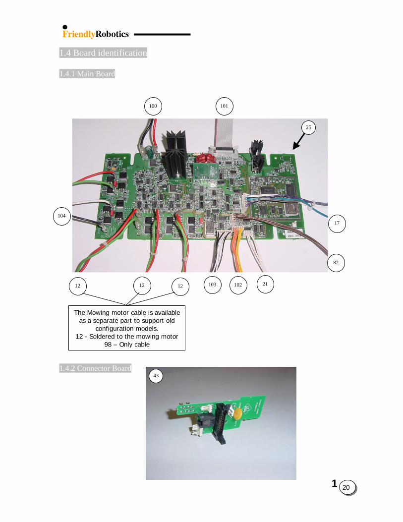
1.4 Board identification 1.4.1 Main Board
100 101 25
104
17
82
21 103 10212 12 12
1.4.
The Mowing motor cable is availableas a separate part to support old
configuration models. 12 - Soldered to the mowing motor
98 – Only cable
2 Connector Board
1
20
43
1
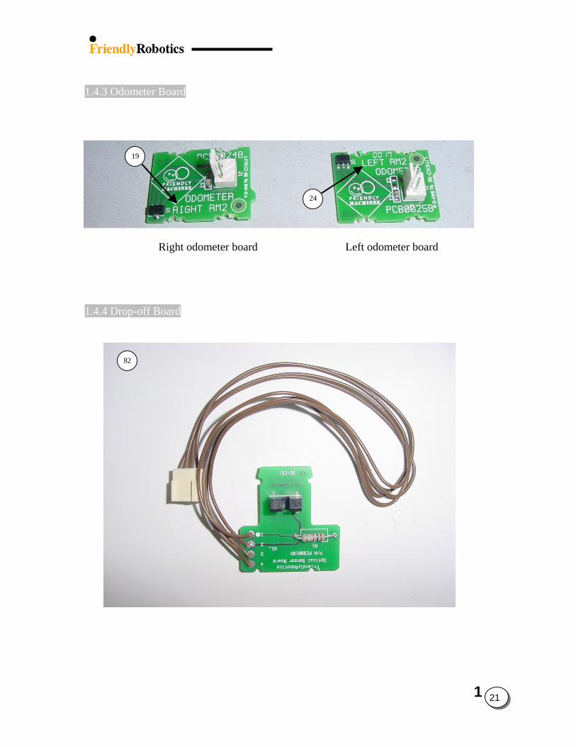
1.4.3 Odometer Board
19
24
Right odometer board Left odometer board
1.4.4 Drop-off Board
82
21
1.5 Wiring layout
1
22
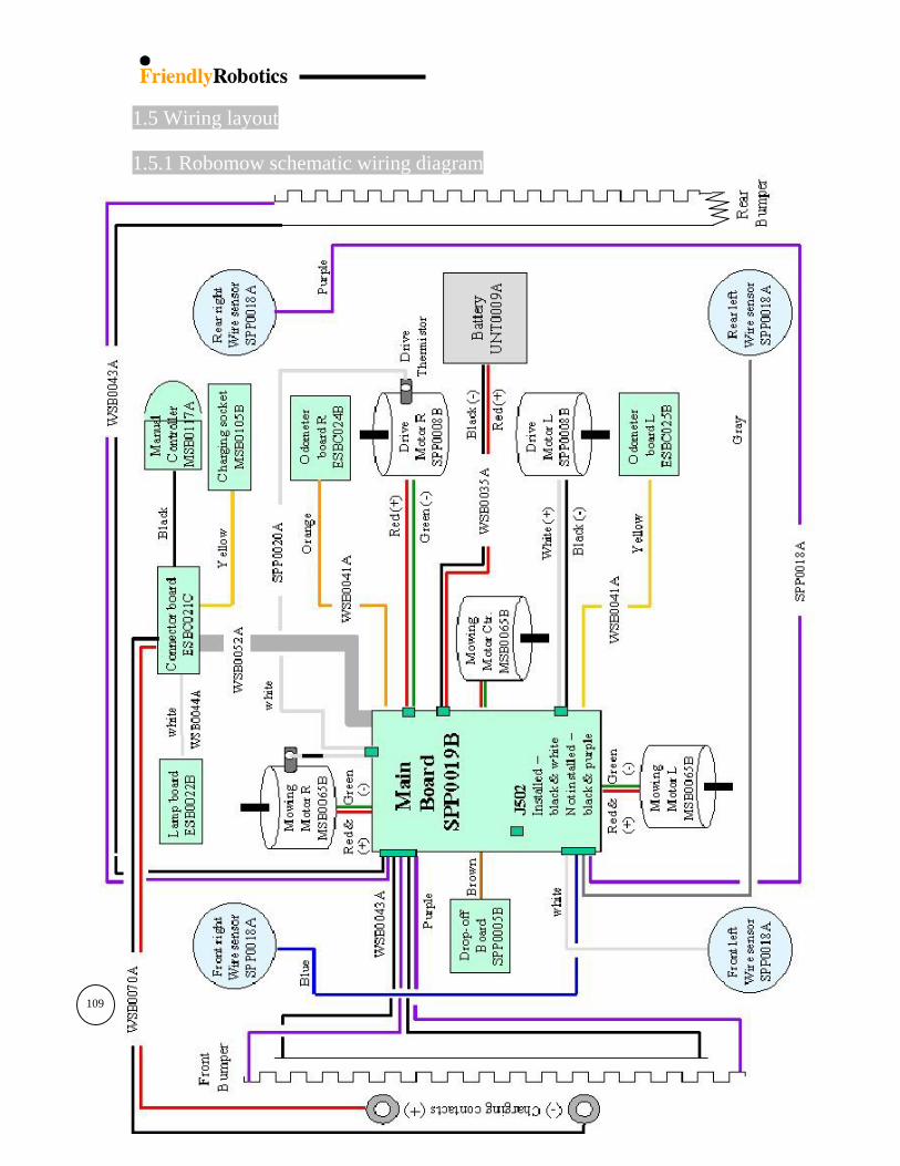
1.5.1 Robomow schematic wiring diagram
109
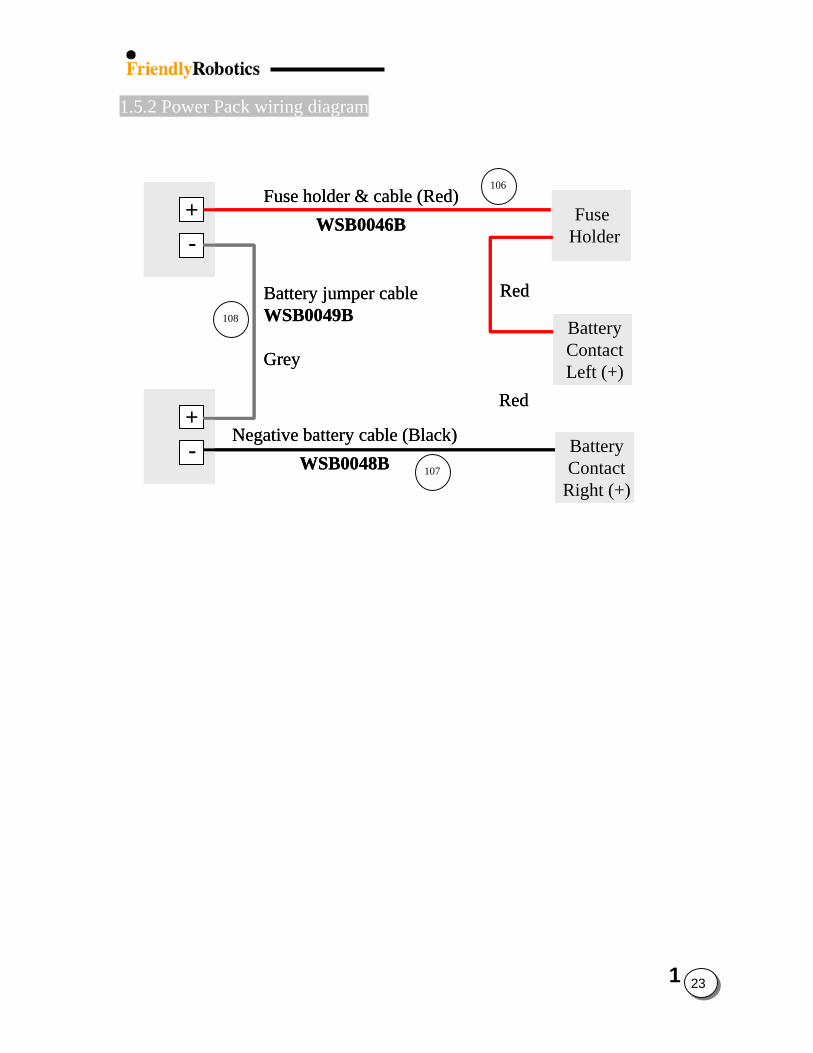
1.5.2 Power Pack wiring diagram
+-
+-
Fuse Holder
BatteryContactLeft (+)
BatteryContact
Right (+)
Fuse holder & cable (Red)WSB0046B
Battery jumper cableWSB0049B
Grey
Red
Negative battery cable (Black)WSB0048B
Red
+-++--
+-++--
Fuse HolderFuse
Holder
BatteryContactLeft (+)
BatteryContactLeft (+)
BatteryContact
Right (+)
BatteryContact
Right (+)
Fuse holder & cable (Red)WSB0046B
Battery jumper cableWSB0049B
Grey
Red
Negative battery cable (Black)WSB0048B
Red
106
108
107
1
23
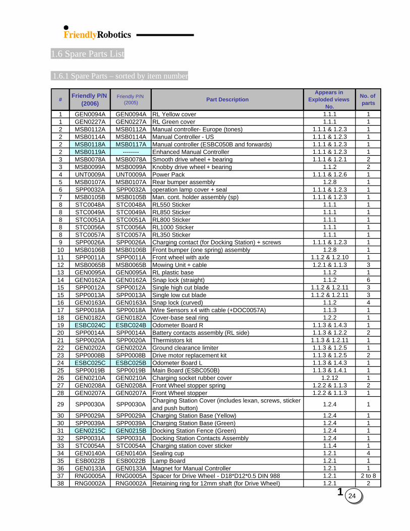
1.6 Spare Parts List
1.6.1 Spare Parts – sorted by item number
24
# Friendly P/N (2006)
Friendly P/N (2005) Part Description
Appears in Exploded views
No.
No. of parts
1 GEN0094A GEN0094A RL Yellow cover 1.1.1 11 GEN0227A GEN0227A RL Green cover 1.1.1 12 MSB0112A MSB0112A Manual controller- Europe (tones) 1.1.1 & 1.2.3 12 MSB0114A MSB0114A Manual Controller - US 1.1.1 & 1.2.3 12 MSB0118A MSB0117A Manual controller (ESBC050B and forwards) 1.1.1 & 1.2.3 12 MSB0119A -------- Enhanced Manual Controller 1.1.1 & 1.2.3 13 MSB0078A MSB0078A Smooth drive wheel + bearing 1.1.1 & 1.2.1 23 MSB0099A MSB0099A Knobby drive wheel + bearing 1.1.2 24 UNT0009A UNT0009A Power Pack 1.1.1 & 1.2.6 15 MSB0107A MSB0107A Rear bumper assembly 1.2.8 16 SPP0032A SPP0032A operation lamp cover + seal 1.1.1 & 1.2.3 17 MSB0105B MSB0105B Man. cont. holder assembly (sp) 1.1.1 & 1.2.3 18 STC0048A STC0048A RL550 Sticker 1.1.1 18 STC0049A STC0049A RL850 Sticker 1.1.1 18 STC0051A STC0051A RL800 Sticker 1.1.1 18 STC0056A STC0056A RL1000 Sticker 1.1.1 18 STC0057A STC0057A RL350 Sticker 1.1.1 19 SPP0026A SPP0026A Charging contact (for Docking Station) + screws 1.1.1 & 1.2.3 1
10 MSB0106B MSB0106B Front bumper (one spring) assembly 1.2.8 111 SPP0011A SPP0011A Front wheel with axle 1.1.2 & 1.2.10 112 MSB0065B MSB0065B Mowing Unit + cable 1.2.1 & 1.1.3 313 GEN0095A GEN0095A RL plastic base 1.1.2 114 GEN0162A GEN0162A Snap lock (straight) 1.1.2 615 SPP0012A SPP0012A Single high cut blade 1.1.2 & 1.2.11 315 SPP0013A SPP0013A Single low cut blade 1.1.2 & 1.2.11 316 GEN0163A GEN0163A Snap lock (curved) 1.1.2 417 SPP0018A SPP0018A Wire Sensors x4 with cable (+DOC0057A) 1.1.3 118 GEN0182A GEN0182A Cover-base seal ring 1.2.2 119 ESBC024C ESBC024B Odometer Board R 1.1.3 & 1.4.3 120 SPP0014A SPP0014A Battery contacts assembly (RL side) 1.1.3 & 1.2.2 221 SPP0020A SPP0020A Thermistors kit 1.1.3 & 1.2.11 122 GEN0202A GEN0202A Ground clearance limiter 1.1.3 & 1.2.5 123 SPP0008B SPP0008B Drive motor replacement kit 1.1.3 & 1.2.5 224 ESBC025C ESBC025B Odometer Board L 1.1.3 & 1.4.3 125 SPP0019B SPP0019B Main Board (ESBC050B) 1.1.3 & 1.4.1 126 GEN0210A GEN0210A Charging socket rubber cover 1.2.12 127 GEN0208A GEN0208A Front Wheel stopper spring 1.2.2 & 1.1.3 228 GEN0207A GEN0207A Front Wheel stopper 1.2.2 & 1.1.3 1
29 SPP0030A SPP0030A Charging Station Cover (includes lexan, screws, sticker and push button) 1.2.4 1
30 SPP0029A SPP0029A Charging Station Base (Yellow) 1.2.4 130 SPP0039A SPP0039A Charging Station Base (Green) 1.2.4 131 GEN0215C GEN0215B Docking Station Fence (Green) 1.2.4 132 SPP0031A SPP0031A Docking Station Contacts Assembly 1.2.4 133 STC0054A STC0054A Charging station cover sticker 1.1.4 134 GEN0140A GEN0140A Sealing cup 1.2.1 435 ESB0022B ESB0022B Lamp Board 1.2.1 136 GEN0133A GEN0133A Magnet for Manual Controller 1.2.1 137 RNG0005A RNG0005A Spacer for Drive Wheel - D18*D12*0.5 DIN 988 1.2.1 2 to 838 RNG0002A RNG0002A Retaining ring for 12mm shaft (for Drive Wheel) 1.2.1 2
1
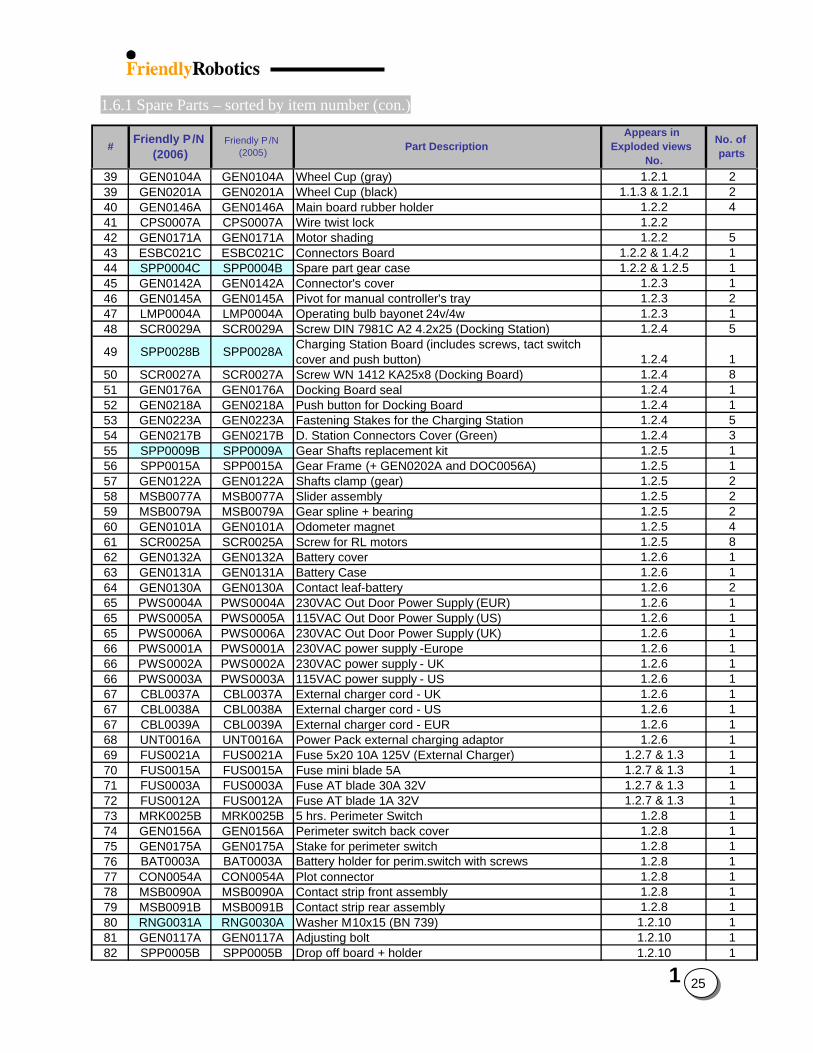
1.6.1 Spare Parts – sorted by item number (con.)
# Friendly P/N (2006)
Friendly P/N (2005) Part Description
Appears in Exploded views
No.
No. of parts
39 GEN0104A GEN0104A Wheel Cup (gray) 1.2.1 239 GEN0201A GEN0201A Wheel Cup (black) 1.1.3 & 1.2.1 240 GEN0146A GEN0146A Main board rubber holder 1.2.2 441 CPS0007A CPS0007A Wire twist lock 1.2.242 GEN0171A GEN0171A Motor shading 1.2.2 543 ESBC021C ESBC021C Connectors Board 1.2.2 & 1.4.2 144 SPP0004C SPP0004B Spare part gear case 1.2.2 & 1.2.5 145 GEN0142A GEN0142A Connector's cover 1.2.3 146 GEN0145A GEN0145A Pivot for manual controller's tray 1.2.3 247 LMP0004A LMP0004A Operating bulb bayonet 24v/4w 1.2.3 148 SCR0029A SCR0029A Screw DIN 7981C A2 4.2x25 (Docking Station) 1.2.4 5
49 SPP0028B SPP0028A Charging Station Board (includes screws, tact switch cover and push button) 1.2.4 1
50 SCR0027A SCR0027A Screw WN 1412 KA25x8 (Docking Board) 1.2.4 851 GEN0176A GEN0176A Docking Board seal 1.2.4 152 GEN0218A GEN0218A Push button for Docking Board 1.2.4 153 GEN0223A GEN0223A Fastening Stakes for the Charging Station 1.2.4 554 GEN0217B GEN0217B D. Station Connectors Cover (Green) 1.2.4 355 SPP0009B SPP0009A Gear Shafts replacement kit 1.2.5 156 SPP0015A SPP0015A Gear Frame (+ GEN0202A and DOC0056A) 1.2.5 157 GEN0122A GEN0122A Shafts clamp (gear) 1.2.5 258 MSB0077A MSB0077A Slider assembly 1.2.5 259 MSB0079A MSB0079A Gear spline + bearing 1.2.5 260 GEN0101A GEN0101A Odometer magnet 1.2.5 461 SCR0025A SCR0025A Screw for RL motors 1.2.5 862 GEN0132A GEN0132A Battery cover 1.2.6 163 GEN0131A GEN0131A Battery Case 1.2.6 164 GEN0130A GEN0130A Contact leaf-battery 1.2.6 265 PWS0004A PWS0004A 230VAC Out Door Power Supply (EUR) 1.2.6 165 PWS0005A PWS0005A 115VAC Out Door Power Supply (US) 1.2.6 165 PWS0006A PWS0006A 230VAC Out Door Power Supply (UK) 1.2.6 166 PWS0001A PWS0001A 230VAC power supply -Europe 1.2.6 166 PWS0002A PWS0002A 230VAC power supply - UK 1.2.6 166 PWS0003A PWS0003A 115VAC power supply - US 1.2.6 167 CBL0037A CBL0037A External charger cord - UK 1.2.6 167 CBL0038A CBL0038A External charger cord - US 1.2.6 167 CBL0039A CBL0039A External charger cord - EUR 1.2.6 168 UNT0016A UNT0016A Power Pack external charging adaptor 1.2.6 169 FUS0021A FUS0021A Fuse 5x20 10A 125V (External Charger) 1.2.7 & 1.3 170 FUS0015A FUS0015A Fuse mini blade 5A 1.2.7 & 1.3 171 FUS0003A FUS0003A Fuse AT blade 30A 32V 1.2.7 & 1.3 172 FUS0012A FUS0012A Fuse AT blade 1A 32V 1.2.7 & 1.3 173 MRK0025B MRK0025B 5 hrs. Perimeter Switch 1.2.8 174 GEN0156A GEN0156A Perimeter switch back cover 1.2.8 175 GEN0175A GEN0175A Stake for perimeter switch 1.2.8 176 BAT0003A BAT0003A Battery holder for perim.switch with screws 1.2.8 177 CON0054A CON0054A Plot connector 1.2.8 178 MSB0090A MSB0090A Contact strip front assembly 1.2.8 179 MSB0091B MSB0091B Contact strip rear assembly 1.2.8 180 RNG0031A RNG0030A Washer M10x15 (BN 739) 1.2.10 181 GEN0117A GEN0117A Adjusting bolt 1.2.10 182 SPP0005B SPP0005B Drop off board + holder 1.2.10 1
1
25
1.6.1 Spare Parts – sorted by item number (con.)
# Friendly P/N (2006)
Friendly P/N (2005) Part Description
Appears in Exploded views
No.
No. of parts
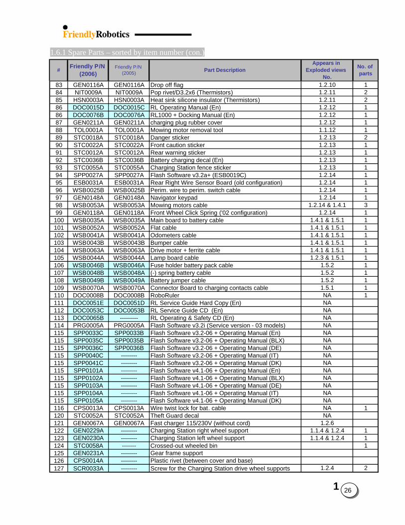
83 GEN0116A GEN0116A Drop off flag 1.2.10 184 NIT0009A NIT0009A Pop rivet/D3.2x6 (Thermistors) 1.2.11 285 HSN0003A HSN0003A Heat sink silicone insulator (Thermistors) 1.2.11 286 DOC0015D DOC0015C RL Operating Manual (En) 1.2.12 186 DOC0076B DOC0076A RL1000 + Docking Manual (En) 1.2.12 187 GEN0211A GEN0211A charging plug rubber cover 1.2.12 188 TOL0001A TOL0001A Mowing motor removal tool 1.1.12 189 STC0018A STC0018A Danger sticker 1.2.13 290 STC0022A STC0022A Front caution sticker 1.2.13 191 STC0012A STC0012A Rear warning sticker 1.2.13 192 STC0036B STC0036B Battery charging decal (En) 1.2.13 193 STC0055A STC0055A Charging Station fence sticker 1.2.13 194 SPP0027A SPP0027A Flash Software v3.2a+ (ESB0019C) 1.2.14 195 ESB0031A ESB0031A Rear Right Wire Sensor Board (old configuration) 1.2.14 196 WSB0025B WSB0025B Perim. wire to perim. switch cable 1.2.14 197 GEN0148A GEN0148A Navigator keypad 1.2.14 198 WSB0053A WSB0053A Mowing motors cable 1.2.14 & 1.4.1 399 GEN0118A GEN0118A Front Wheel Click Spring ('02 configuration) 1.2.14 1
100 WSB0035A WSB0035A Main board to battery cable 1.4.1 & 1.5.1 1101 WSB0052A WSB0052A Flat cable 1.4.1 & 1.5.1 1102 WSB0041A WSB0041A Odometers cable 1.4.1 & 1.5.1 1103 WSB0043B WSB0043B Bumper cable 1.4.1 & 1.5.1 1104 WSB0063A WSB0063A Drive motor + ferrite cable 1.4.1 & 1.5.1 1105 WSB0044A WSB0044A Lamp board cable 1.2.3 & 1.5.1 1106 WSB0046B WSB0046A Fuse holder battery pack cable 1.5.2 1107 WSB0048B WSB0048A (-) spring battery cable 1.5.2 1108 WSB0049B WSB0049A Battery jumper cable 1.5.2 1109 WSB0070A WSB0070A Connector Board to charging contacts cable 1.5.1 1110 DOC0008B DOC0008B RoboRuler NA 1111 DOC0051E DOC0051D RL Service Guide Hard Copy (En) NA112 DOC0053C DOC0053B RL Service Guide CD (En) NA113 DOC0065B --------- RL Operating & Safety CD (En) NA114 PRG0005A PRG0005A Flash Software v3.2i (Service version - 03 models) NA115 SPP0033C SPP0033B Flash Software v3.2-06 + Operating Manual (En) NA115 SPP0035C SPP0035B Flash Software v3.2-06 + Operating Manual (BLX) NA115 SPP0036C SPP0036B Flash Software v3.2-06 + Operating Manual (DE) NA115 SPP0040C -------- Flash Software v3.2-06 + Operating Manual (IT) NA115 SPP0041C -------- Flash Software v3.2-06 + Operating Manual (DK) NA115 SPP0101A -------- Flash Software v4.1-06 + Operating Manual (En) NA115 SPP0102A -------- Flash Software v4.1-06 + Operating Manual (BLX) NA115 SPP0103A -------- Flash Software v4.1-06 + Operating Manual (DE) NA115 SPP0104A -------- Flash Software v4.1-06 + Operating Manual (IT) NA115 SPP0105A -------- Flash Software v4.1-06 + Operating Manual (DK) NA116 CPS0013A CPS0013A Wire twist lock for bat. cable NA 1120 STC0052A STC0052A Theft Guard decal NA121 GEN0067A GEN0067A Fast charger 115/230V (without cord) 1.2.6122 GEN0229A -------- Charging Station right wheel support 1.1.4 & 1.2.4 1123 GEN0230A -------- Charging Station left wheel support 1.1.4 & 1.2.4 1124 STC0058A ------- Crossed-out wheeled bin 1125 GEN0231A -------- Gear frame support 126 CPS0014A -------- Plastic rivet (between cover and base)127 SCR0033A -------- Screw for the Charging Station drive wheel supports 1.2.4 2
1
26
1.6.2 Spare Parts – sorted by Friendly part number
27
# Friendly P/N (2006)
Friendly P/N (2005) Part Description
Appears in Exploded views
No.
No. of parts
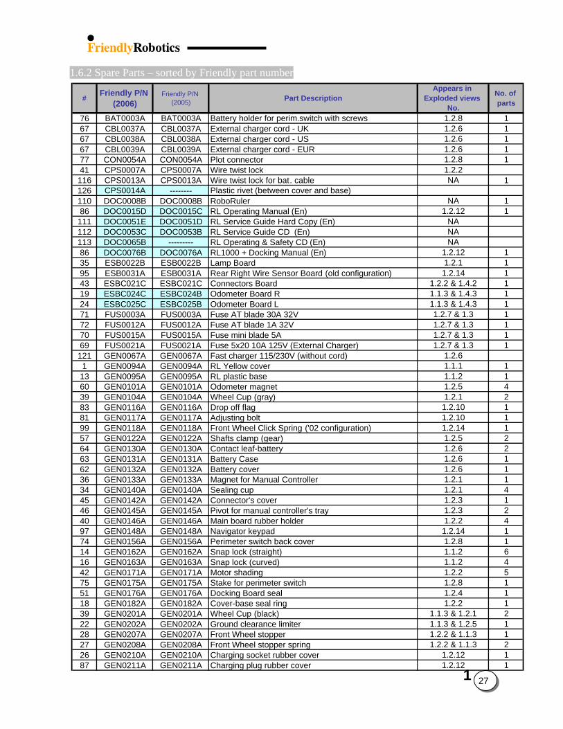
76 BAT0003A BAT0003A Battery holder for perim.switch with screws 1.2.8 167 CBL0037A CBL0037A External charger cord - UK 1.2.6 167 CBL0038A CBL0038A External charger cord - US 1.2.6 167 CBL0039A CBL0039A External charger cord - EUR 1.2.6 177 CON0054A CON0054A Plot connector 1.2.8 141 CPS0007A CPS0007A Wire twist lock 1.2.2
116 CPS0013A CPS0013A Wire twist lock for bat. cable NA 1126 CPS0014A -------- Plastic rivet (between cover and base)110 DOC0008B DOC0008B RoboRuler NA 186 DOC0015D DOC0015C RL Operating Manual (En) 1.2.12 1
111 DOC0051E DOC0051D RL Service Guide Hard Copy (En) NA112 DOC0053C DOC0053B RL Service Guide CD (En) NA113 DOC0065B --------- RL Operating & Safety CD (En) NA86 DOC0076B DOC0076A RL1000 + Docking Manual (En) 1.2.12 135 ESB0022B ESB0022B Lamp Board 1.2.1 195 ESB0031A ESB0031A Rear Right Wire Sensor Board (old configuration) 1.2.14 143 ESBC021C ESBC021C Connectors Board 1.2.2 & 1.4.2 119 ESBC024C ESBC024B Odometer Board R 1.1.3 & 1.4.3 124 ESBC025C ESBC025B Odometer Board L 1.1.3 & 1.4.3 171 FUS0003A FUS0003A Fuse AT blade 30A 32V 1.2.7 & 1.3 172 FUS0012A FUS0012A Fuse AT blade 1A 32V 1.2.7 & 1.3 170 FUS0015A FUS0015A Fuse mini blade 5A 1.2.7 & 1.3 169 FUS0021A FUS0021A Fuse 5x20 10A 125V (External Charger) 1.2.7 & 1.3 1
121 GEN0067A GEN0067A Fast charger 115/230V (without cord) 1.2.61 GEN0094A GEN0094A RL Yellow cover 1.1.1 1
13 GEN0095A GEN0095A RL plastic base 1.1.2 160 GEN0101A GEN0101A Odometer magnet 1.2.5 439 GEN0104A GEN0104A Wheel Cup (gray) 1.2.1 283 GEN0116A GEN0116A Drop off flag 1.2.10 181 GEN0117A GEN0117A Adjusting bolt 1.2.10 199 GEN0118A GEN0118A Front Wheel Click Spring ('02 configuration) 1.2.14 157 GEN0122A GEN0122A Shafts clamp (gear) 1.2.5 264 GEN0130A GEN0130A Contact leaf-battery 1.2.6 263 GEN0131A GEN0131A Battery Case 1.2.6 162 GEN0132A GEN0132A Battery cover 1.2.6 136 GEN0133A GEN0133A Magnet for Manual Controller 1.2.1 134 GEN0140A GEN0140A Sealing cup 1.2.1 445 GEN0142A GEN0142A Connector's cover 1.2.3 146 GEN0145A GEN0145A Pivot for manual controller's tray 1.2.3 240 GEN0146A GEN0146A Main board rubber holder 1.2.2 497 GEN0148A GEN0148A Navigator keypad 1.2.14 174 GEN0156A GEN0156A Perimeter switch back cover 1.2.8 114 GEN0162A GEN0162A Snap lock (straight) 1.1.2 616 GEN0163A GEN0163A Snap lock (curved) 1.1.2 442 GEN0171A GEN0171A Motor shading 1.2.2 575 GEN0175A GEN0175A Stake for perimeter switch 1.2.8 151 GEN0176A GEN0176A Docking Board seal 1.2.4 118 GEN0182A GEN0182A Cover-base seal ring 1.2.2 139 GEN0201A GEN0201A Wheel Cup (black) 1.1.3 & 1.2.1 222 GEN0202A GEN0202A Ground clearance limiter 1.1.3 & 1.2.5 128 GEN0207A GEN0207A Front Wheel stopper 1.2.2 & 1.1.3 127 GEN0208A GEN0208A Front Wheel stopper spring 1.2.2 & 1.1.3 226 GEN0210A GEN0210A Charging socket rubber cover 1.2.12 187 GEN0211A GEN0211A Charging plug rubber cover 1.2.12 1
1
1.6.2 Spare Parts – sorted by Friendly part number (con.)
# Friendly P/N (2006)
Friendly P/N (2005) Part Description
Appears in Exploded views
No.
No. of parts
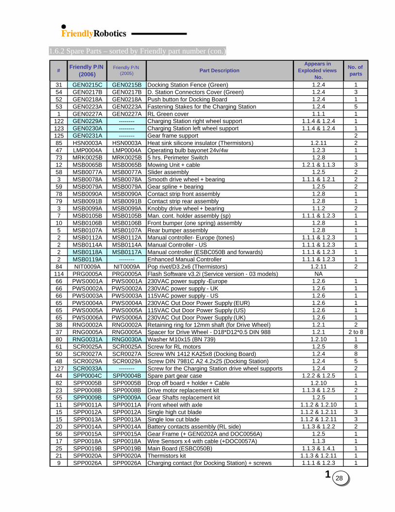
31 GEN0215C GEN0215B Docking Station Fence (Green) 1.2.4 154 GEN0217B GEN0217B D. Station Connectors Cover (Green) 1.2.4 352 GEN0218A GEN0218A Push button for Docking Board 1.2.4 153 GEN0223A GEN0223A Fastening Stakes for the Charging Station 1.2.4 51 GEN0227A GEN0227A RL Green cover 1.1.1 1
122 GEN0229A -------- Charging Station right wheel support 1.1.4 & 1.2.4 1123 GEN0230A -------- Charging Station left wheel support 1.1.4 & 1.2.4 1125 GEN0231A -------- Gear frame support 285 HSN0003A HSN0003A Heat sink silicone insulator (Thermistors) 1.2.11 247 LMP0004A LMP0004A Operating bulb bayonet 24v/4w 1.2.3 173 MRK0025B MRK0025B 5 hrs. Perimeter Switch 1.2.8 112 MSB0065B MSB0065B Mowing Unit + cable 1.2.1 & 1.1.3 358 MSB0077A MSB0077A Slider assembly 1.2.5 23 MSB0078A MSB0078A Smooth drive wheel + bearing 1.1.1 & 1.2.1 2
59 MSB0079A MSB0079A Gear spline + bearing 1.2.5 278 MSB0090A MSB0090A Contact strip front assembly 1.2.8 179 MSB0091B MSB0091B Contact strip rear assembly 1.2.8 13 MSB0099A MSB0099A Knobby drive wheel + bearing 1.1.2 27 MSB0105B MSB0105B Man. cont. holder assembly (sp) 1.1.1 & 1.2.3 1
10 MSB0106B MSB0106B Front bumper (one spring) assembly 1.2.8 15 MSB0107A MSB0107A Rear bumper assembly 1.2.8 12 MSB0112A MSB0112A Manual controller- Europe (tones) 1.1.1 & 1.2.3 12 MSB0114A MSB0114A Manual Controller - US 1.1.1 & 1.2.3 12 MSB0118A MSB0117A Manual controller (ESBC050B and forwards) 1.1.1 & 1.2.3 12 MSB0119A -------- Enhanced Manual Controller 1.1.1 & 1.2.3 184 NIT0009A NIT0009A Pop rivet/D3.2x6 (Thermistors) 1.2.11 2
114 PRG0005A PRG0005A Flash Software v3.2i (Service version - 03 models) NA66 PWS0001A PWS0001A 230VAC power supply -Europe 1.2.6 166 PWS0002A PWS0002A 230VAC power supply - UK 1.2.6 166 PWS0003A PWS0003A 115VAC power supply - US 1.2.6 165 PWS0004A PWS0004A 230VAC Out Door Power Supply (EUR) 1.2.6 165 PWS0005A PWS0005A 115VAC Out Door Power Supply (US) 1.2.6 165 PWS0006A PWS0006A 230VAC Out Door Power Supply (UK) 1.2.6 138 RNG0002A RNG0002A Retaining ring for 12mm shaft (for Drive Wheel) 1.2.1 237 RNG0005A RNG0005A Spacer for Drive Wheel - D18*D12*0.5 DIN 988 1.2.1 2 to 880 RNG0031A RNG0030A Washer M10x15 (BN 739) 1.2.10 161 SCR0025A SCR0025A Screw for RL motors 1.2.5 850 SCR0027A SCR0027A Screw WN 1412 KA25x8 (Docking Board) 1.2.4 848 SCR0029A SCR0029A Screw DIN 7981C A2 4.2x25 (Docking Station) 1.2.4 5
127 SCR0033A -------- Screw for the Charging Station drive wheel supports 1.2.4 244 SPP0004C SPP0004B Spare part gear case 1.2.2 & 1.2.5 182 SPP0005B SPP0005B Drop off board + holder + Cable 1.2.10 123 SPP0008B SPP0008B Drive motor replacement kit 1.1.3 & 1.2.5 255 SPP0009B SPP0009A Gear Shafts replacement kit 1.2.5 111 SPP0011A SPP0011A Front wheel with axle 1.1.2 & 1.2.10 115 SPP0012A SPP0012A Single high cut blade 1.1.2 & 1.2.11 315 SPP0013A SPP0013A Single low cut blade 1.1.2 & 1.2.11 320 SPP0014A SPP0014A Battery contacts assembly (RL side) 1.1.3 & 1.2.2 256 SPP0015A SPP0015A Gear Frame (+ GEN0202A and DOC0056A) 1.2.5 117 SPP0018A SPP0018A Wire Sensors x4 with cable (+DOC0057A) 1.1.3 125 SPP0019B SPP0019B Main Board (ESBC050B) 1.1.3 & 1.4.1 121 SPP0020A SPP0020A Thermistors kit 1.1.3 & 1.2.11 19 SPP0026A SPP0026A Charging contact (for Docking Station) + screws 1.1.1 & 1.2.3 1
1
28
1.6.2 Spare Parts – sorted by Friendly part number (con.)
# Friendly P /N (2006)
Friendly P /N (2005) Part Description
Appears in Exploded views
No.
No. of parts
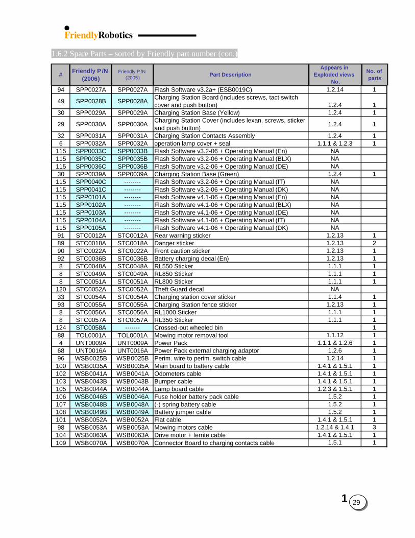
94 SPP0027A SPP0027A Flash Software v3.2a+ (ESB0019C) 1.2.14 1
49 SPP0028B SPP0028A Charging Station Board (includes screws, tact switch cover and push button) 1.2.4 1
30 SPP0029A SPP0029A Charging Station Base (Yellow) 1.2.4 1
29 SPP0030A SPP0030A Charging Station Cover (includes lexan, screws, sticker and push button) 1.2.4 1
32 SPP0031A SPP0031A Charging Station Contacts Assembly 1.2.4 16 SPP0032A SPP0032A operation lamp cover + seal 1.1.1 & 1.2.3 1
115 SPP0033C SPP0033B Flash Software v3.2-06 + Operating Manual (En) NA115 SPP0035C SPP0035B Flash Software v3.2-06 + Operating Manual (BLX) NA115 SPP0036C SPP0036B Flash Software v3.2-06 + Operating Manual (DE) NA30 SPP0039A SPP0039A Charging Station Base (Green) 1.2.4 1115 SPP0040C -------- Flash Software v3.2-06 + Operating Manual (IT) NA115 SPP0041C -------- Flash Software v3.2-06 + Operating Manual (DK) NA115 SPP0101A -------- Flash Software v4.1-06 + Operating Manual (En) NA115 SPP0102A -------- Flash Software v4.1-06 + Operating Manual (BLX) NA115 SPP0103A -------- Flash Software v4.1-06 + Operating Manual (DE) NA115 SPP0104A -------- Flash Software v4.1-06 + Operating Manual (IT) NA115 SPP0105A -------- Flash Software v4.1-06 + Operating Manual (DK) NA91 STC0012A STC0012A Rear warning sticker 1.2.13 189 STC0018A STC0018A Danger sticker 1.2.13 290 STC0022A STC0022A Front caution sticker 1.2.13 192 STC0036B STC0036B Battery charging decal (En) 1.2.13 18 STC0048A STC0048A RL550 Sticker 1.1.1 18 STC0049A STC0049A RL850 Sticker 1.1.1 18 STC0051A STC0051A RL800 Sticker 1.1.1 1
120 STC0052A STC0052A Theft Guard decal NA33 STC0054A STC0054A Charging station cover sticker 1.1.4 193 STC0055A STC0055A Charging Station fence sticker 1.2.13 18 STC0056A STC0056A RL1000 Sticker 1.1.1 18 STC0057A STC0057A RL350 Sticker 1.1.1 1
124 STC0058A ------- Crossed-out wheeled bin 188 TOL0001A TOL0001A Mowing motor removal tool 1.1.12 14 UNT0009A UNT0009A Power Pack 1.1.1 & 1.2.6 168 UNT0016A UNT0016A Power Pack external charging adaptor 1.2.6 196 WSB0025B WSB0025B Perim. wire to perim. switch cable 1.2.14 1100 WSB0035A WSB0035A Main board to battery cable 1.4.1 & 1.5.1 1102 WSB0041A WSB0041A Odometers cable 1.4.1 & 1.5.1 1103 WSB0043B WSB0043B Bumper cable 1.4.1 & 1.5.1 1105 WSB0044A WSB0044A Lamp board cable 1.2.3 & 1.5.1 1106 WSB0046B WSB0046A Fuse holder battery pack cable 1.5.2 1107 WSB0048B WSB0048A (-) spring battery cable 1.5.2 1108 WSB0049B WSB0049A Battery jumper cable 1.5.2 1101 WSB0052A WSB0052A Flat cable 1.4.1 & 1.5.1 198 WSB0053A WSB0053A Mowing motors cable 1.2.14 & 1.4.1 3104 WSB0063A WSB0063A Drive motor + ferrite cable 1.4.1 & 1.5.1 1109 WSB0070A WSB0070A Connector Board to charging contacts cable 1.5.1 1
1
29
1
30
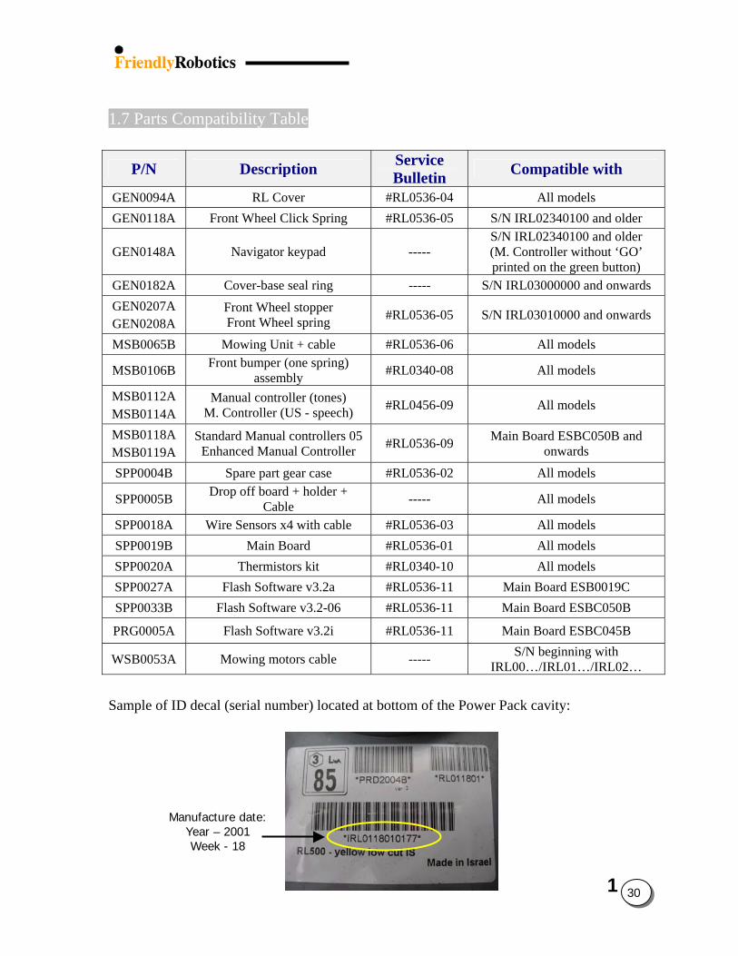
1.7 Parts Compatibility Table
P/N Description Service Bulletin Compatible with
GEN0094A RL Cover #RL0536-04 All models GEN0118A Front Wheel Click Spring #RL0536-05 S/N IRL02340100 and older
GEN0148A Navigator keypad ----- S/N IRL02340100 and older (M. Controller without ‘GO’ printed on the green button)
GEN0182A Cover-base seal ring ----- S/N IRL03000000 and onwards GEN0207A GEN0208A
Front Wheel stopper Front Wheel spring #RL0536-05 S/N IRL03010000 and onwards
MSB0065B Mowing Unit + cable #RL0536-06 All models
MSB0106B Front bumper (one spring) assembly #RL0340-08 All models
MSB0112A MSB0114A
Manual controller (tones) M. Controller (US - speech) #RL0456-09 All models
MSB0118A MSB0119A
Standard Manual controllers 05 Enhanced Manual Controller #RL0536-09 Main Board ESBC050B and
onwards
SPP0004B Spare part gear case #RL0536-02 All models
SPP0005B Drop off board + holder + Cable ----- All models
SPP0018A Wire Sensors x4 with cable #RL0536-03 All models SPP0019B Main Board #RL0536-01 All models SPP0020A Thermistors kit #RL0340-10 All models SPP0027A Flash Software v3.2a #RL0536-11 Main Board ESB0019C SPP0033B Flash Software v3.2-06 #RL0536-11 Main Board ESBC050B
PRG0005A Flash Software v3.2i #RL0536-11 Main Board ESBC045B
WSB0053A Mowing motors cable ----- S/N beginning with IRL00…/IRL01…/IRL02…
Sample of ID decal (serial number) located at bottom of the Power Pack cavity:
Manufacture date: Year – 2001 Week - 18
2 1
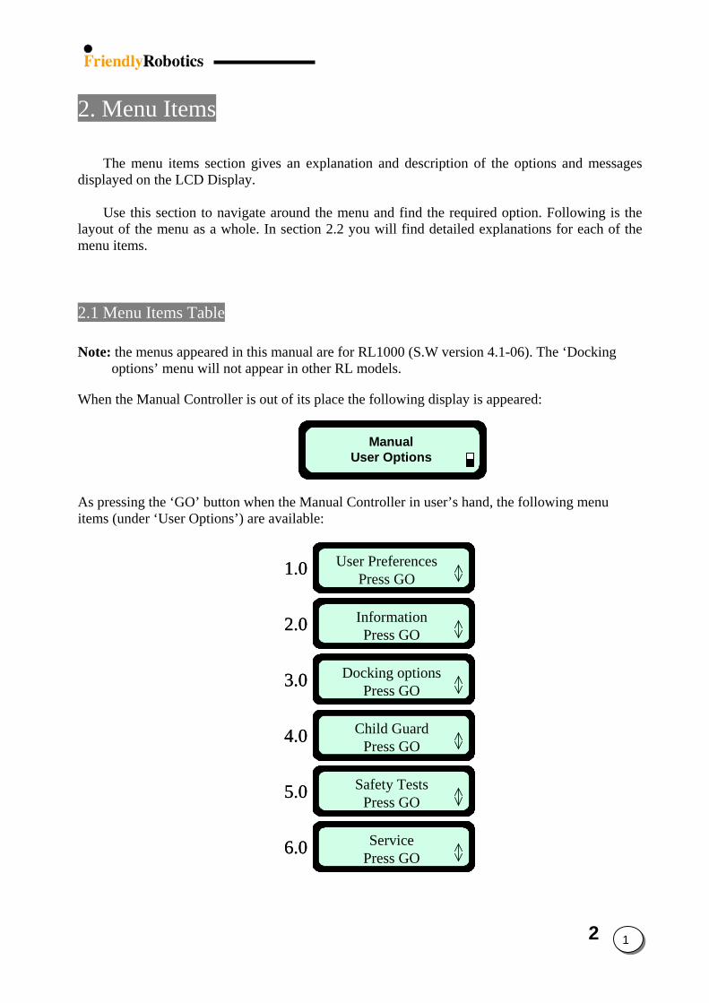
2. Menu Items
The menu items section gives an explanation and description of the options and messages
displayed on the LCD Display. Use this section to navigate around the menu and find the required option. Following is the
layout of the menu as a whole. In section 2.2 you will find detailed explanations for each of the menu items.
2.1 Menu Items Table Note: the menus appeared in this manual are for RL1000 (S.W version 4.1-06). The ‘Docking
options’ menu will not appear in other RL models. When the Manual Controller is out of its place the following display is appeared:
ManualUser Options
ManualUser Options
As pressing the ‘GO’ button when the Manual Controller in user’s hand, the following menu items (under ‘User Options’) are available:
InformationPress GO
User PreferencesPress GO
Child GuardPress GO
Docking optionsPress GO
ServicePress GO
Safety TestsPress GO
1.0
2.0
3.0
4.0
5.0
6.0
InformationPress GO
User PreferencesPress GO
Child GuardPress GO
Docking optionsPress GO
ServicePress GO
Safety TestsPress GO
InformationPress GO
User PreferencesPress GO
Child GuardPress GO
Docking optionsPress GO
ServicePress GO
Safety TestsPress GO
1.0
2.0
3.0
4.0
5.0
6.0
2 2
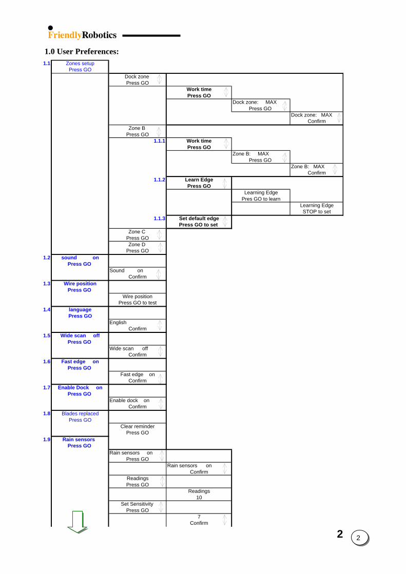
1.0 User Preferences: 1.1 Zones setup
Press GODock zone Press GO
Work timePress GO
Dock zone: MAXPress GO
Dock zone: MAXConfirm
Zone B Press GO
1.1.1 Work timePress GO
Zone B: MAXPress GO
Zone B: MAXConfirm
1.1.2 Learn EdgePress GO
Learning EdgePres GO to learn
Learning EdgeSTOP to set
1.1.3 Set default edgePress GO to set
Zone C Press GOZone D
Press GO1.2 sound on
Press GO Sound on
Confirm1.3 Wire position
Press GO Wire position
Press GO to test1.4 language
Press GOEnglish
Confirm1.5 Wide scan off
Press GO Wide scan off
Confirm1.6 Fast edge on
Press GO Fast edge on
Confirm1.7 Enable Dock on
Press GO Enable dock on
Confirm1.8 Blades replaced
Press GOClear reminder
Press GO1.9 Rain sensors
Press GO Rain sensors on
Press GORain sensors on
ConfirmReadingsPress GO
Readings10
Set Sensitivity Press GO
7Confirm
2 3
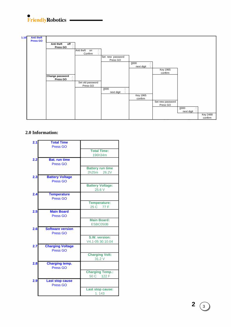
1.10 Anti theftPress GO
Anti theft offPress GO
Anti theft onConfirm
Set new passwordPress GO
0000next digit
Key 1965confirm
Change passwordPress GO
Set old passwordPress GO
0000next digit
Key 1965confirm
Set new passwordPress GO
0000next digit
Key 2468confirm
2.0 Information: 2.1 Total Time
Press GOTotal Time:
196h34m2.2 Bat. run time
Press GOBattery run time2h25m 26.2V
2.3 Battery VoltagePress GO
Battery Voltage:25.6 V
2.4 TemperaturePress GO
Temperature:25 C 77 F
2.5 Main BoardPress GO
Main Board:ESBC050B
2.6 Software versionPress GO
S.W. version:V4.1-05 30.10.04
2.7 Charging VoltagePress GO
Charging Volt:31.2 V
2.8 Charging temp.Press GO
Charging Temp.:50 C 122 F
2.9 Last stop causePress GO
Last stop cause:1. 143
2 4
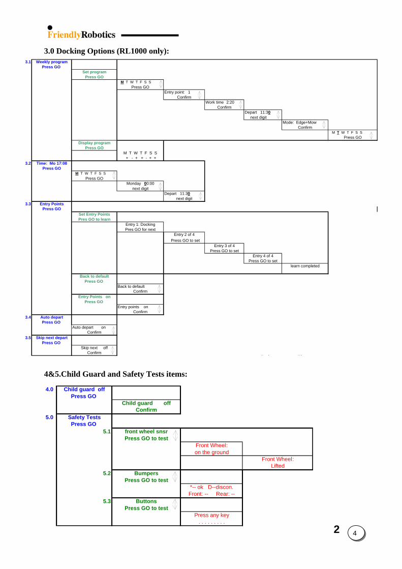
3.0 Docking Options (RL1000 only):
3.1 Weekly programPress GO
Set programPress GO
M T W T F S SPress GO
Entry point: 1Confirm
Work time 2:20 Confirm
Depart 11:30 next digit
Mode: Edge+MowConfirm
M T W T F S SPress GO
Display programPress GO
M T W T F S S + - + + - + +
3.2 Time: Mo 17:08Press GO
M T W T F S SPress GO
Monday 00:00next digit
Depart 11:30next digit
3.3 Entry PointsPress GO
Set Entry PointsPres GO to learn
Entry 1: DockingPres GO for next
Entry 2 of 4 Press GO to set
Entry 3 of 4Press GO to set
Entry 4 of 4Press GO to set
learn completed
Back to defaultPress GO
Back to defaultConfirm
Entry Points onPress GO
Entry points onConfirm
3.4 Auto departPress GO
Auto depart onConfirm
3.5 Skip next departPress GO
Skip next offConfirm
4&5.Child Guard and Safety Tests items:
4.0 Child guard offPress GO
Child guard offConfirm
5.0 Safety TestsPress GO
5.1 front wheel snsrPress GO to test
Front Wheel:on the ground
Front Wheel:Lifted
*-- ok D--discon.Front: -- Rear: --
Press any key. . . . . . . . .
5.2 BumpersPress GO to test
5.3 ButtonsPress GO to test
2 5
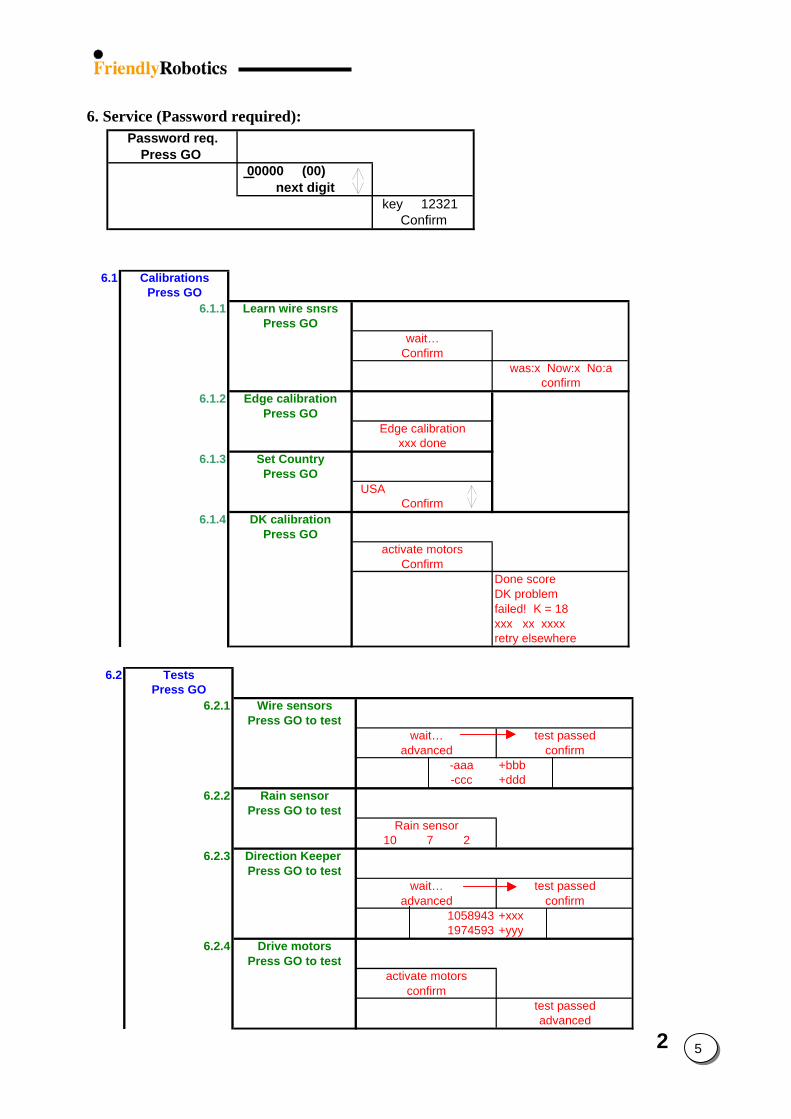
6. Service (Password required): Password req.
Press GO 00000 (00)
next digit key 12321
Confirm
6.1 Calibrations
Press GO6.1.1 Learn wire snsrs
Press GOwait…
Confirmwas:x Now:x No:a
confirm
Edge calibrationxxx done
USAConfirm
activate motorsConfirm
Done scoreDK problemfailed! K = 18xxx xx xxxxretry elsewher
6.1.2 Edge calibrationPress GO
6.1.3 Set CountryPress GO
6.1.4 DK calibrationPress GO
e
6.2 TestsPress GO
6.2.1 Wire sensorsPress GO to test
wait… test passedadvanced confirm
-aaa +bbb -ccc +ddd
6.2.2 Rain sensorPress GO to test
Rain sensor10 7 2
6.2.3 Direction Keeper Press GO to test
wait… test passedadvanced confirm
1058943 +xxx1974593 +yyy
6.2.4 Drive motorsPress GO to test
activate motorsconfirm
test passedadvanced
2 6
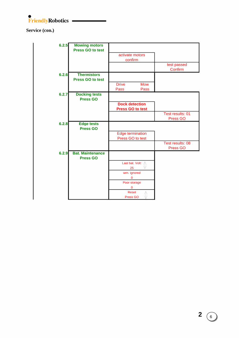
Service (con.) 6.2.5 Mowing motors
Press GO to testactivate motors
confirmtest passed
Confirm6.2.6 Thermistors
Press GO to test Drive Mow Pass Pass
6.2.7 Docking testsPress GO
Dock detectionPress GO to test
Test results: 01Press GO
6.2.8 Edge testsPress GO
6.2.9 Bat. MaintenancePress GO
Edge terminationPress GO to test
Test results: 08Press GO
Last bat. Volt:25
wrn. ignored0
Poor storage0
ResetPress GO
2
7
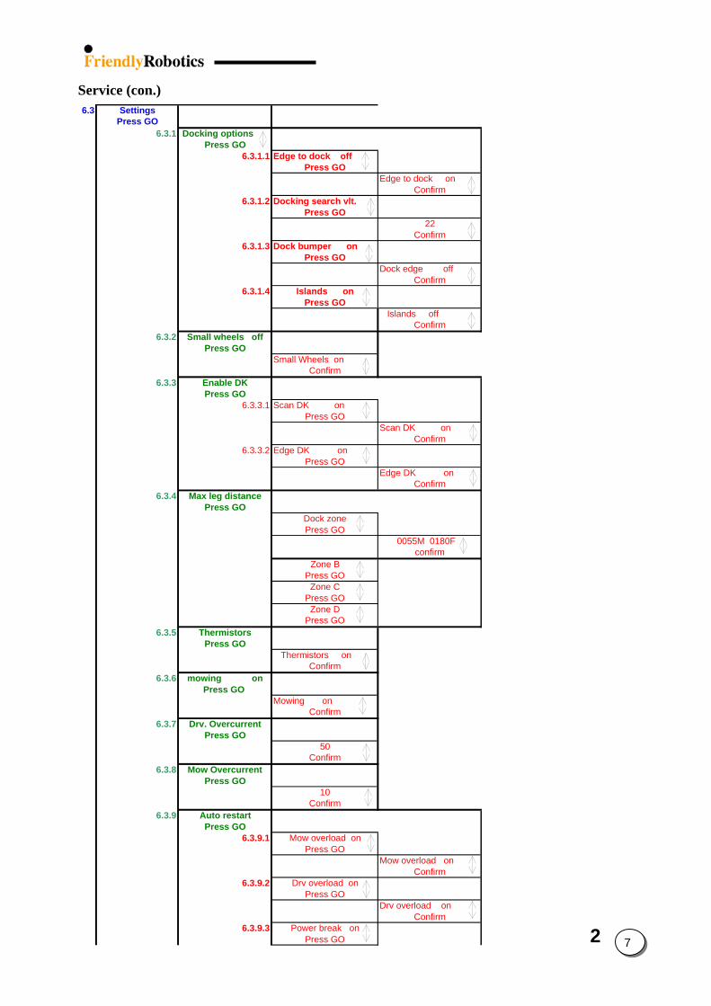
6.3.2 Small wheels offPress GO
6.3.3 Enable DKPress GO
6.3.4 Max leg distancePress GO
6.3.5 ThermistorsPress GO
6.3.6 mowing onPress GO
6.3.7 Dr
Service (con.) 6.3 Settings
Press GO6.3.1 Docking options
Press GO6.3.1.1 Edge to dock off
Press GOEdge to dock on
Confirm6.3.1.2 Docking search vlt.
Press GO22
Confirm6.3.1.3 Dock bumper on
Press GODock edge off
Confirm6.3.1.4 Islands on
Press GO Islands off
Confirm
Small Wheels onConfirm
6.3.3.1 Scan DK onPress GO
Scan DK onConfirm
6.3.3.2 Edge DK onPress GO
Edge DK onConfirm
Dock zonePress GO
0055M 0180F confirm
Zone BPress GO
Zone CPress GO
Zone DPress GO
Thermistors onConfirm
Mowing onConfirm
v. OvercurrentPress GO
6.3.8 Mow OvercurrentPress GO
6.3.9 Auto restartPress GO
50Confirm
10Confirm
6.3.9.1 Mow overload onPress GO
Mow overload onConfirm
6.3.9.2 Drv overload onPress GO
Drv overload onConfirm
6.3.9.3 Power break onPress GO
2 8
2.2 Menu Items Explanation
They following section explain the different menu items appeared in section 2.1 above:
1.0 User Preferences
1.1 Zones Setup Allows user to set the parameters that are specific per zone
1.1.1 Work Time Allows the user the option of setting the operating time from the ‘MAX’ default setting to times ranging from 20 minutes up to 2:40 hours. This option is available for up to 4 different zones, Dock Zone, Zone B, C or D. Having four different zones can allow you to set operating time for several different zones that are of varying sizes, not requiring the same operating time for mowing. Note: for Dock zone it is possible to set different work time per operation when setting the automatic weekly program. 1.1.2 Learn Edge The default distance for edge mowing is approximately 1.5 to 2 rounds around the perimeter. This feature allows the user to learn a specific distance in each operating zone in order to cause the mower to cut the edge a specific distance, such as one full round. This can increase the efficiency by minimizing the time spent on edge mowing. In some rare cases, because of some unique geometry of the lawn, a mower may not complete edge under the normal default operation. This feature allows you to overcome the issue by learning the edge in that zone. It will remain as a learned distance until the edge is re-learned or the factory default edge is selected.
1.1.3 Set Default Edge Returns the edge mowing distance back to the factory default in the zone selected.
1.2 Sound The sound feature allows the user to disable all audio effects except those related with safety.
1.3 Wire Position Allows user to test the wire position in ‘Edge’ mode while the mowing motors are switched off to prevent any damage to the perimeter wire after the initial setup of the wire is completed. 1.4 Language Changes the LCD display on the Manual Controller to read in alternate languages.
1.5 Wide Scan Wide scan is a second navigation method, where the angles between subsequent legs are increased. This method should be selected in lawns where the mower appears to be driving back and forth along the same path, not advancing to the left or right while mowing.
2 9
1.6 Fast Edge Fast edge enables Robomow tracking the Perimeter Wire in faster drive speed. This option is enabled in Dock zone only. The fast speed has two speed levels, when the faster level is used when the mowing motors are witched off and Robomow tracks the Perimeter Wire in ‘Searching dock’ or ‘Searching entry’ modes.
1.7 Enable Dock This option should be set to ‘on’ when using Docking Station to enable the Docking options to the user. If it set to ‘off’ the Docking menus are hidden.
1.8 Blades replaced ‘Replace blades’ message is displayed after every 200 hours of operation. The message is displayed upon ‘GO’ pressing for the next 10 hours of operation or till the user chooses the ‘Blades replaced’ option under the ‘User preferences’ menu. 1.9 Rain Sensor The Rain sensor feature enables the mower to detect rain and to skip or stop the operation as the rain is detected. There are three options under the ‘Rain sensor’ menu: Rain sensor on/off - allows turning the rain sensor feature off to enable operation in rain and
wet grass conditions. Reading – Shows the actual reading of the rain sensor. Set sensitivity – Enables to set the sensitivity of the rain sensor in which the mower will detect
rain below the threshold set. The default sensitivity set in the factory is 4, it means that in any reading below 4 the mower will detect rain and will not operate.
1.10 Anti-theft
The anti-theft system provides the user a disabling function that will prevent anyone from using or driving the Robomow unless they have the valid code to enter. You will be prompted to enter a four-digit code of your choice to use as your personal security code. Use the scroll arrows in order to change each digit position to a different number and then press ‘GO’ to move to the next digit to select. You will find a place to record your personal security code in Chapter 8 of this manual.
To change the password chooses the ‘Change password’ option under the ‘Anti theft’ menu. You will be promoted to enter your old password before setting the new one.
2 10
2.0 Information
2.1 Total time A very important information menu item, this shows the total operating time of the mower. This is valuable information used for warranty and repair services. It can also indicate the usage model of the mower, for example using the mower on multiple properties instead of for homeowner use as it is designed. This number will only reset when a main board has been replaced. It is also a required line entry for a warranty claim.
2.2 Bat. run time The left number indicates the last battery run time from GO pressing till ‘Recharge battery’ message is displayed and the right number indicates the battery voltage at the beginning of the operation (measured when the GO is pressed). 2.3 Battery voltage Displays the current voltage of the power pack. 2.4 Temperature Displays the ambience temperature in the mower. 2.5 Main Board Main Board will display the version of CPU used in this particular mower. This is essentially an information menu, but can be used in the event an issue is found to only apply to one particular CPU.
2.6 Software version Identifies the software version operating in this mower. An information menu, but can be important if a particular issue is found and it applies to only a specific version of software. 2.7 Charging voltage Displays the charging voltage. 2.8 Charging temp. Displays the charging temperature (measured on the Main Board). 2.9 Last stop cause Displays the last 10 stop cause numbers (refer to Last Stop Cause Table in paragraph 5.7).

2 11
3.0 Docking Options (RL1000 only)
3.1 Weekly Program 3.1.1 Set Weekly Program
One of the advantages of having a docking station for the Robomow is the ability to set an automatic weekly program. The user can set the weekly program at the beginning of a season and not worry about mowing again all season long. Four parameters are required to be selected: Day/s, Work time, hour/s, operating mode/s. Select the day or days, the work time and the time in which you would like the mower to automatically depart and mow your lawn. Also select whether to have the edge mowed or not. If ‘Learn edge’ is done, another option in the weekly program is available to the user – to set the ‘Entry point’ per specific day. While the mower is docked, the next departure scheduled will be displayed at the top right corner of the LCD. It will display the day of the next departure, the time and mode.
3.1.2 Display Program
Select this option in order to view the weekly program. The days of the week will be displayed on the LCD (M, T, W, T, F, S, S) and a + or – under each letter. A ‘+’ represents an active day, meaning that the mower will mow during that day, at the time scheduled.
3.2 Time The first step before setting the weekly program is to set the current time: day of the week and time (hours & minutes). Note that the clock is on a 24-hour military time scale. This feature is relevant only if a weekly program has been set. While the mower is docked, the current time will be displayed at the top left corner of the LCD. Note that whenever the power pack is removed from the mower, it is required to set the time. 3.3 Entry Points ‘Entry point’ is defined as the point, where the mower leaves the Edge and turn into the lawn to mow the inner area. In order to ensure better area coverage in mowing, the mower has default of three different entry points. The ‘Entry points’ option enable to set different entry points from those set by the factory to your lawn.
3.3.1 Set Entry Points It is possible to set up to four points (includes the Docking Station itself, which is always defined as entry point number one and cannot be canceled). 3.3.2 Back to Default Selecting ‘Back to default’ restores the factory default entry points – there is no distance in the memory and the mower should complete the lawn’s edge at least once before it will use the default of 30% and 60% percentages of the perimeter as entry points.
3.3.3 Entry Points (on/off) Allows user not to use the entry points. When setting the ‘Entry points’ to ‘off’ the mower will start the mowing of the inner area always from the Docking Station.
3.4 Auto Depart Allows user to shut off the weekly program when setting the ‘Auto depart’ to ‘off’.
2 12
3.5 Skip Next Depart Allows user to skip the next scheduled operation.
4.0 Child Guard Child Guard is an option that allows disabling operation of the buttons of the Manual Controller unless a pre-set two step button sequence is pressed first. While locked, the up arrow key and then the ‘C’ key must be pressed in order to un-lock the buttons for use. Once Child Guard is ON, the buttons will re-lock after about 60 seconds if none of the buttons were pressed. This is a very low-level safety feature intended to prevent button use or unintended operation by very young children. The factory default for this feature is OFF. 5.0 Safety Tests The Safety Tests function provides a means for the customer to check the operation of the basic safety systems of the mower. It encompasses the front wheel sensor, the front and rear bumpers and the buttons on the Manual Controller. By entering this menu, the customer can select which system to test and following the screen prompts, test each of the systems. 6.0 Service The Service menu, while accessed under the User Options screen, is not a customer menu option. It is only to be used by a trained service technician and requires a specific 5-digit code to be entered in order to access the sub-menus. 6.1 CALIBRATIONS
6.1.1 Learn Wire Sensors ‘Learn wire sensors’ is the process of teaching the wire sensors their position relative to the mower as well as to the signal of the perimeter wire. This process is used when the fault “Move From Wire” is displayed, the wire sensors have been replaced and when a main board has been replaced under a service repair. 6.1.2 Edge Calibration Edge calibration is the process of defining how the mower will track the perimeter wire on edge mowing. This is pre-set from the factory to basically track on center. This process would generally be used only when a main board is replaced under a service repair or on replacement of the wire sensors.
2 13
6.1.3 Set Country When a mower is first placed in operation, by default the customer is required to ‘Set Country’ prior to the mower operation. This setting helps define the area of the world in which the mower is operating in order to better define the magnetic field of the earth, which is used by the Robomow for navigation. This option would be used to change a country where the customer inadvertently selected the wrong country prior to the first operation or when a main board has been replaced under a service repair. 6.1.4 DK Calibration When a mower is first placed in operation, by default the customer is required to perform DK (direction keeper) calibration‘ prior to the mower operation. DK calibration is the process of defining the detail level of magnetic north for the system. It is done at the users lawn and is only required to be done once. This option would be used if the mower has been moved to a new location over 160 km (100 miles) from the original location and when a main board has been replaced under a service repair. 6.2 TESTS
6.2.1 Wire Sensors Wire sensors is a diagnostic process that tests the operation of the four wire sensors on the mower. It has two levels of testing, basic and advanced. Under the basic testing it is a ‘pass-fail’ test with a fault code listed for the failure message. The advanced testing shows the physical reading of each of the four wire sensors, which on occasion may be helpful, is troubleshooting. Typically, the basic test is sufficient. 6.2.2 Rain Sensor Rain sensor is a diagnostics process that tests the reading of the rain sensor on the Manual Controller. 3 numbers are displayed in the test: 1) The left number is the rain sensor reading (the actual reading received from the rain sensor – it
is updated every 5 seconds). 2) The middle number is the rain sensor sensitivity, which enables to set the sensitivity of the rain
sensor in which the mower will detect rain below the threshold set. The default sensitivity set in the factory is 7, it means that in any reading below 7 the mower will detect rain and will not operate.
3) The right number is the rain sensor status when 0 means that rain sensor's existence is unknown, 1 means that rain sensor does not exist and 2 means that rain sensor exists.
6.2.3 Direction Keeper Direction keeper is a diagnostic process used to test the DK system or on-board compass (called the flux gate). It has two levels of testing, basic and advanced. Under the basic testing it is a ‘pass-fail’ test with a fault code listed for the failure message. The advanced test will show the physical readings of the compass and is seldom used.
6.2.4 Drive Motors Drive motors is the process of testing the drive motors and odometer system of the mower. It has two levels of testing, basic and advanced. The advanced testing is not functional in this system. Under the basic testing it is a ‘pass-fail’ test with a fault code listed for the failure message.
2 14
6.2.5 Mowing Motors Mowing motors is the process of testing the mowing motor system of the mower. It has one basic level of testing. Under the basic testing it is a ‘pass-fail’ test with a fault code listed for the failure message. 6.2.6 Thermistors Is used for testing the two Thermistors of the mower, one is located on the right Drive Motor and the other on the right Mowing Motor. When this test is selected, an automatic testing process will take place resulting in a ‘Pass/Fail’ message.
6.2.7 Docking Dock Detection Is used for testing the entry process of the mower to the Docking Station. After this test is selected, place the Manual Controller in its place and choose the ‘Go to dock’ option. An automatic testing process will take place resulting in number, which indicates the result of the test. 6.2.8 Edge Edge Termination Is used for testing the edge mode in case, which the mower does not complete the edge all around the perimeter or when the mower does not drive back to the Docking Station at the end of the operation. After this test is selected, operate the mower in Edge mode. At the end of the edge, the mower will display a ‘Test result: X’, which is the reason for Edge termination in this performed test. 6.2.9 Battery Maintenance Battery maintenance is a multiple menu selection. It can provide valuable information of the customers’ maintenance habits regarding the mower as well as help in identifying a faulty power pack. Last Battery Voltage –the last measured voltage of the power pack will be displayed. This number is updated frequently when in charging mode and in automatic operation mode. If the mower was in deep sleep mode, the last recorded voltage prior to deep sleep will be recorded. This can be useful in determining charger operation by viewing the voltage over time. Additionally, it can be used to view voltage over time while in operation to understand a discharge rate to determine power pack condition. Warning Ignored – the energy management system of the mower will alert both audibly and by displaying a text message prompting the user to connect the mower to the charger when not in use (if the customer has failed to do so). The warnings vary in frequency of time and loudness, depending on the time disconnected from the charger. This warning system will function for approximately 48 hours before shutting down and entering a deep sleep mode for energy conservation. This selection indicates how many times the customer has ignored the alert system and allowed the mower to enter the deep sleep mode. This can indicate poor maintenance by the customer and could cause diminished power pack performance and service life. While any number here is a cause for concern and illustrates the need to educate the user how to properly mainten the mower, a count of 2 or more is serious and can damage the power pack.
2 15
Poor Storage – poor storage counter indicates how many times the mower was put into operation where the power pack capacity was less than 80% of fully charged. This essentially indicates how often the mower was used prior to the power pack being fully re-charged, where the count will not start until there is a 20% capacity loss from fully charged. The 20% criteria is important, as many people will use the mower in several smaller areas in addition to the main area. A smaller area will discharge the power pack, but not to the 20% level, so we do not want to count such operations. A high count here, greater than 3 or 4 indicates that the user is not fully re-charging the power pack. If a customer claims that that’s his only solution to mow the entire lawn, it is recommended that they purchase an additional power pack and an external charger. Lastly, if the voltage of a power pack, when inserted, is less than 90% of the last measured voltage, that indicates that the power pack has not been fully charged at the end of the previous season, which is critical for good service life (winter/storage charging instructions are given in the operating & safety manual). Reset – allows resetting all listed battery parameters back to zero when a new power pack has been put in service or possibly if a service repair was done, which may have affected the counters. 6.3 SETTINGS
6.3.1 Docking Options 6.3.1.1 Edge to Dock
Enable the mower to complete the edge operation from the Docking Station back to the Docking Station without any condition, otherwise there are few events that may cause the mower to leave the edge, such as distance limit or number of turns to the left.
6.3.1.2 Docking search vlt.
Option to increase the ‘Searching dock’ threshold voltage (22.5 and 23.0) in case, which the mower doesn't succeed to drive back to the Charging Station because of low battery voltage.
6.3.1.3 Dock bumper
Changing this option to 'off' will change the bumper behavior so it will make bypass in every bumper event during 'Edge' mode.
6.3.1.4 Islands
Setting this option to ‘off’ allow the mower to acquire the Perimeter Wire immediately as starting to search for the Charging Station with no need to converge to the end of the lawn.
6.3.2 Small Wheels In some markets there are two types of wheels for different Robomow models. There are knobby wheels (as in all US models) and there are smaller diameter wheels without treads. If this setting is inadvertently selected, the mower will not navigate properly and will likely not drive in straight lines. It is important to have the setting right according to the type of wheels.
2 16
6.3.3 Enable DK Enable DK is a feature that is helpful when operating the mower in an area where magnetic interference is suspected in a certain lawn or when the Robomow is operated indoors, i.e. at an exhibition. Indoors exhibitions are typically on concrete floors that contain a great deal of metals. This large amount of metal will skew the magnetic field causing the mower to run in curved lines rather than straight lines. Turning the ‘Enable DK’ feature off will allow the mower to navigate solely on wheel rotation measurement, thereby not using the magnetic field of the earth. This will allow for straight lines in a show environment. The default of this feature is always on. Enable DK is divided into 2 modes: edge and scan and it is possible to disable the DK either in edge or scan. Disabling the DK in the 2 modes enables to operate the mower without compass at all (or when the compass is faulty). 6.3.4 Max leg distance Enable to set the max distance between the perimeter wires in every zone. There is a monitoring system that detects the wire sensors readings during operation. If the readings are not changed for some time (it depends on the distance between the wires), it means that the mower is probably stuck in place. For example: in lawn 10 by 30, the mower will not drive more than 10 meters with the same readings, but in lawn 40 by 90 it may drive for 60 meters with no changes in the wire sensors readings. If during scanning it is found that the max leg distance set by the user is shorter than what does the mower calculate, then the S.W will update it. 6.3.5 Thermistors Enable Thermistors is set to ‘on’ by default at the manufacturer. This option is used when replacing a Main Board in old configuration Robomow, which has no Thermistors – in such case there are two options: 1. Add Thermistors to the Robomow, as the new Main Board supports this option. 2. Set the ‘Thermistors’ option to ‘off’ if the Robomow does not have Thermistors. 6.3.6 Mowing The mowing feature provides the ability to disable the operation of the mowing motors. All other aspects of the mower will perform normally, however the blades will not rotate. This feature is useful when testing the set up of the perimeter wire prior to having the wire fully pegged to the ground, preventing the risk of cutting it. Additionally, it is a feature that can be used when using the mower in exhibitions, for safety reasons. 6.3.7 Drv. Overcurrent Option to set the drive over current (load) threshold in which the mower will change the drive direction. 6.3.8 Mow Overcurrent Option to set the mow over current (load) threshold in which the mower will change direction to move from the area with high grass.
2 17
6.3.9 Auto Restart This option enables to set the cases in which Robomow restarts the operation automatically within an hour after it has stopped during the operation.
6.3.9.1 Drive Overload If the mower stops with the following ‘Drive overload - cooling, wait…’(10 min above 100 or 1 sec above 105), it will stay awake for up to 60 minutes with the displayed message and blinking operating light. If the mower cooled down to allowed temperature that enables the operation (Drive - 85 Celsius), the mower will automatically renew the operation from the point he has stopped.
6.3.9.2 Drive Overload If the mower stops with the following ‘Mow overload - cooling, wait…’(10 min above 90 or 1 sec above 100), it will stay awake for up to 60 minutes with the displayed message and blinking operating light. If the mower cooled down to allowed temperature that enables the operation (Mow - 80 Celsius), the mower will automatically renew the operation from the point he has stopped.
6.3.9.3 Power Break Electrical power interruption - In every signal interruption the RL1000 will stop with ‘Waiting for signal…’ message. If the signal comes back within 60 minutes from the stop, the mower will restart the operation automatically, otherwise it will stop with ‘No wire signal – press GO’. The Operating Lamp is blinking all the time that the mower is waiting.
6.3.10 Special Display Choosing the ‘Special display’ option enables to display the relevant parameters to tested process (such as temp, volt and sensor readings) and to perform detailed diagnostics. After a specific display is selected use the CANCEL (‘C’) button to toggle between normal and special display, and the STOP button to terminate the special display.
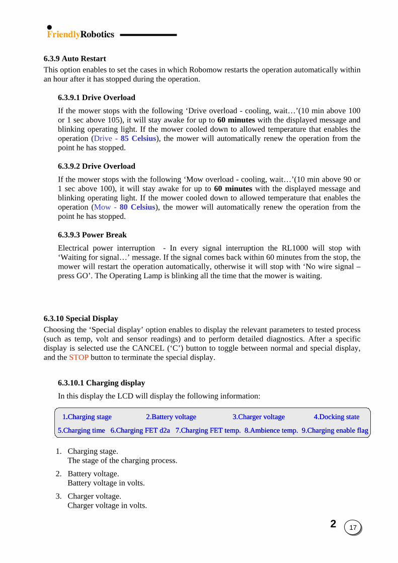
6.3.10.1 Charging display
In this display the LCD will display the following information:
1.Charging stage 2.Battery voltage 3.Charger voltage 4.Docking state
5.Charging time 6.Charging FET d2a 7.Charging FET temp. 8.Ambience temp. 9.Charging enable flag
1.Charging stage 2.Battery voltage 3.Charger voltage 4.Docking state
5.Charging time 6.Charging FET d2a 7.Charging FET temp. 8.Ambience temp. 9.Charging enable flag
1.Charging stage 2.Battery voltage 3.Charger voltage 4.Docking state
5.Charging time 6.Charging FET d2a 7.Charging FET temp. 8.Ambience temp. 9.Charging enable flag
1. Charging stage.
The stage of the charging process.
2. Battery voltage. Battery voltage in volts.
3. Charger voltage. Charger voltage in volts.
2 18
4. Docking state. If the charging is done through the charging socket (placed in the Manual Controller Holder) then ‘00’ is displayed in the docking state.
If the charging is done through the Docking Station, one of the following numbers is displayed:
01 - Charging through the docking station
02 - Problem in charging through the docking station
03 - Robomow is trying to reconnect to the docking station for recharging
04 - Automatic departure time
05 - The user initiated the departure time
06 - Disconnected from charging in order to cool down because of overheat in the ambience-charging temp.
07 - Disconnected from charging in order to cool down because of overheat in the charging FET temp.
08 - Disconnected from charging in order to cool down because of overheat which is caused when battery voltage is too high during charging.
09 - Disconnected from charging in order to heat up when needed
10- Disconnect from charging in order to perform the ‘Learn entry points’ sequence
11 - Disconnected from docking contacts
5. Charging time. Indicates the charging time in hours from the time the Robomow is connected to the Power Supply/Docking Station.
6. Charging FET d2a.
Indicates the charging FET state (for minimal charging voltage value is 250 – stage 4 in the charging process, for maximal charging voltage value is 60 – stage 1 in the charging process)
Definition: FET (Field-Effect Transistor) A transistor whose control, or gate, signal creates an electro-magnetic field, which turns the transistor ON or OFF.
7. Charging FET temperature.
Indicates FET temperature (ºC) while in charging. If temperature > 125ºC then cooling is required.
8. Ambience temperature.
Indicates the ambience temperature (ºC).
9. Charging enable flag.
Indicates if charging is enabled. 0 – Charging is disabled. 1 – Charging is enabled.
2
19
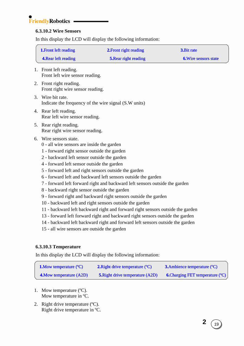
6.3.10.2 Wire Sensors In this display the LCD will display the following information:
1.Front left reading 2.Front right reading 3.Bit rate
4.Rear left reading 5.Rear right reading 6.Wire sensors state
1.Front left reading 2.Front right reading 3.Bit rate
4.Rear left reading 5.Rear right reading 6.Wire sensors state
1.Front left reading 2.Front right reading 3.Bit rate
4.Rear left reading 5.Rear right reading 6.Wire sensors state
1. Front left reading. Front left wire sensor reading.
2. Front right reading. Front right wire sensor reading.
3. Wire bit rate. Indicate the frequency of the wire signal (S.W units)
4. Rear left reading. Rear left wire sensor reading.
5. Rear right reading. Rear right wire sensor reading.
6. Wire sensors state. 0 - all wire sensors are inside the garden 1 - forward right sensor outside the garden 2 - backward left sensor outside the garden 4 - forward left sensor outside the garden 5 - forward left and right sensors outside the garden 6 - forward left and backward left sensors outside the garden 7 - forward left forward right and backward left sensors outside the garden 8 - backward right sensor outside the garden 9 - forward right and backward right sensors outside the garden 10 - backward left and right sensors outside the garden 11 - backward left backward right and forward right sensors outside the garden 13 - forward left forward right and backward right sensors outside the garden 14 - backward left backward right and forward left sensors outside the garden 15 - all wire sensors are outside the garden
6.3.10.3 Temperature In this display the LCD will display the following information:
1.Mow temperature (ºC) 2.Right drive temperature (ºC) 3.Ambience temperature (ºC)
4.Mow temperature (A2D) 5.Right drive temperature (A2D) 6.Charging FET temperature (ºC)
1.Mow temperature (ºC) 2.Right drive temperature (ºC) 3.Ambience temperature (ºC)
4.Mow temperature (A2D) 5.Right drive temperature (A2D) 6.Charging FET temperature (ºC)
1.Mow temperature (ºC) 2.Right drive temperature (ºC) 3.Ambience temperature (ºC)
4.Mow temperature (A2D) 5.Right drive temperature (A2D) 6.Charging FET temperature (ºC)
1. Mow temperature (ºC). Mow temperature in ºC.
2. Right drive temperature (ºC). Right drive temperature in ºC.
2
20
3. Ambience temperature (ºC). Ambience temperature in ºC.
4. Mow temperature (a2d). Mow temperature in a2d. Otherwise - over current.
5. Right drive temperature (a2d). Right drive temperature in a2d.
6. Charging FET temperature (ºC). Charging FET temperature in ºC.
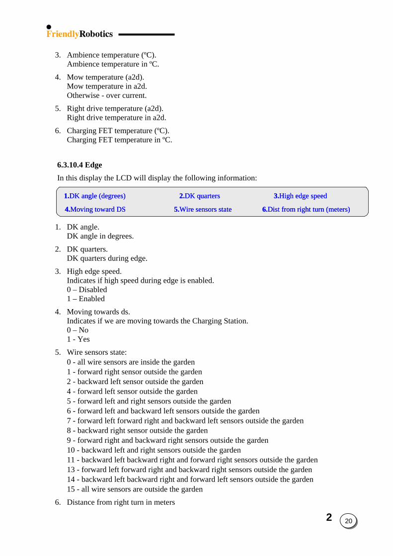
6.3.10.4 Edge In this display the LCD will display the following information:
1.DK angle (degrees) 2.DK quarters 3.High edge speed
4.Moving toward DS 5.Wire sensors state 6.Dist from right turn (meters)
1.DK angle (degrees) 2.DK quarters 3.High edge speed
4.Moving toward DS 5.Wire sensors state 6.Dist from right turn (meters)
1.DK angle (degrees) 2.DK quarters 3.High edge speed
4.Moving toward DS 5.Wire sensors state 6.Dist from right turn (meters)
1. DK angle. DK angle in degrees.
2. DK quarters. DK quarters during edge.
3. High edge speed. Indicates if high speed during edge is enabled. 0 – Disabled 1 – Enabled
4. Moving towards ds. Indicates if we are moving towards the Charging Station. 0 – No 1 - Yes
5. Wire sensors state: 0 - all wire sensors are inside the garden 1 - forward right sensor outside the garden 2 - backward left sensor outside the garden 4 - forward left sensor outside the garden 5 - forward left and right sensors outside the garden 6 - forward left and backward left sensors outside the garden 7 - forward left forward right and backward left sensors outside the garden 8 - backward right sensor outside the garden 9 - forward right and backward right sensors outside the garden 10 - backward left and right sensors outside the garden 11 - backward left backward right and forward right sensors outside the garden 13 - forward left forward right and backward right sensors outside the garden 14 - backward left backward right and forward left sensors outside the garden 15 - all wire sensors are outside the garden
6. Distance from right turn in meters
2
21
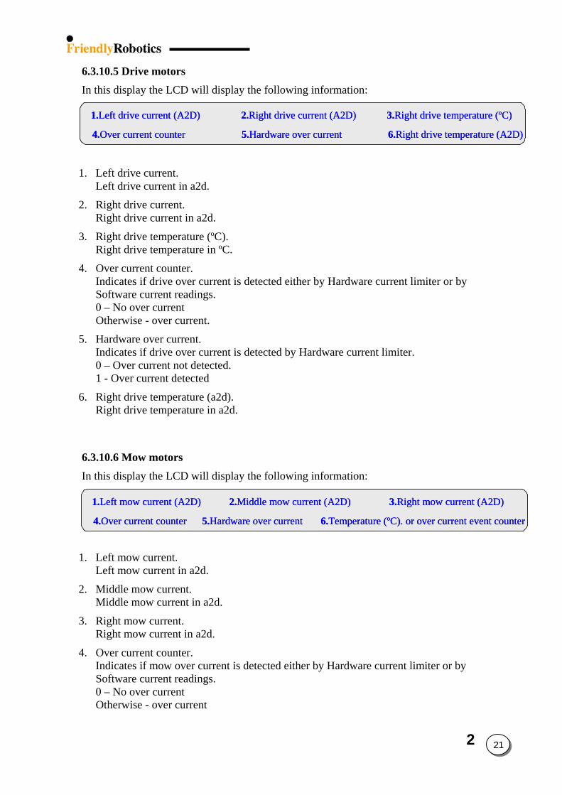
6.3.10.5 Drive motors In this display the LCD will display the following information:
1.Left drive current (A2D) 2.Right drive current (A2D) 3.Right drive temperature (ºC)
4.Over current counter 5.Hardware over current 6.Right drive temperature (A2D)
1.Left drive current (A2D) 2.Right drive current (A2D) 3.Right drive temperature (ºC)
4.Over current counter 5.Hardware over current 6.Right drive temperature (A2D)
1.Left drive current (A2D) 2.Right drive current (A2D) 3.Right drive temperature (ºC)
4.Over current counter 5.Hardware over current 6.Right drive temperature (A2D)
1. Left drive current. Left drive current in a2d.
2. Right drive current. Right drive current in a2d.
3. Right drive temperature (ºC). Right drive temperature in ºC.
4. Over current counter. Indicates if drive over current is detected either by Hardware current limiter or by Software current readings. 0 – No over current Otherwise - over current.
5. Hardware over current. Indicates if drive over current is detected by Hardware current limiter. 0 – Over current not detected. 1 - Over current detected
6. Right drive temperature (a2d). Right drive temperature in a2d.
6.3.10.6 Mow motors In this display the LCD will display the following information:
1.Left mow current (A2D) 2.Middle mow current (A2D) 3.Right mow current (A2D)
4.Over current counter 5.Hardware over current 6.Temperature (ºC). or over current event counter
1.Left mow current (A2D) 2.Middle mow current (A2D) 3.Right mow current (A2D)
4.Over current counter 5.Hardware over current 6.Temperature (ºC). or over current event counter
1.Left mow current (A2D) 2.Middle mow current (A2D) 3.Right mow current (A2D)
4.Over current counter 5.Hardware over current 6.Temperature (ºC). or over current event counter
1. Left mow current. Left mow current in a2d.
2. Middle mow current. Middle mow current in a2d.
3. Right mow current. Right mow current in a2d.
4. Over current counter. Indicates if mow over current is detected either by Hardware current limiter or by Software current readings. 0 – No over current Otherwise - over current
2 22
.
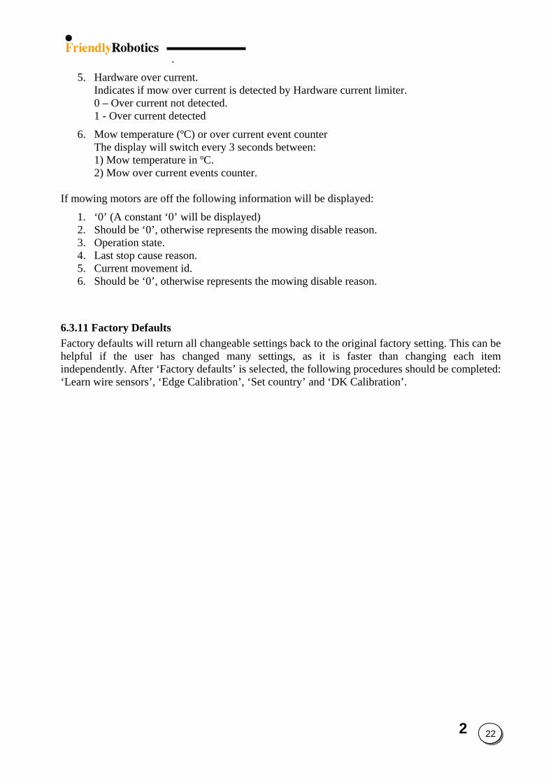
5. Hardware over current. Indicates if mow over current is detected by Hardware current limiter. 0 – Over current not detected. 1 - Over current detected
6. Mow temperature (ºC) or over current event counter The display will switch every 3 seconds between: 1) Mow temperature in ºC. 2) Mow over current events counter.
If mowing motors are off the following information will be displayed:
1. ‘0’ (A constant ‘0’ will be displayed) 2. Should be ‘0’, otherwise represents the mowing disable reason. 3. Operation state. 4. Last stop cause reason. 5. Current movement id. 6. Should be ‘0’, otherwise represents the mowing disable reason.
6.3.11 Factory Defaults Factory defaults will return all changeable settings back to the original factory setting. This can be helpful if the user has changed many settings, as it is faster than changing each item independently. After ‘Factory defaults’ is selected, the following procedures should be completed: ‘Learn wire sensors’, ‘Edge Calibration’, ‘Set country’ and ‘DK Calibration’.
3 1
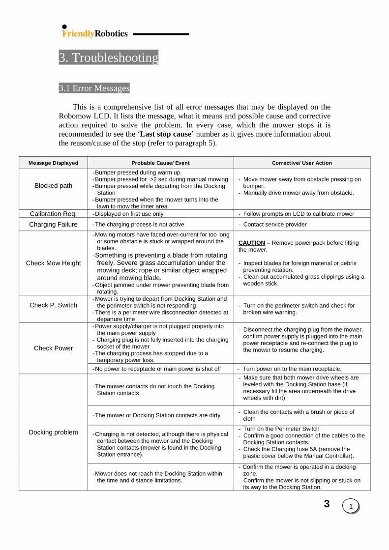
3. Troubleshooting 3.1 Error Messages
This is a comprehensive list of all error messages that may be displayed on the
Robomow LCD. It lists the message, what it means and possible cause and corrective action required to solve the problem. In every case, which the mower stops it is recommended to see the ‘Last stop cause’ number as it gives more information about the reason/cause of the stop (refer to paragraph 5).
Message Displayed Probable Cause/Event Corrective/User Action
Blocked path
- Bumper pressed during warm up. - Bumper pressed for >2 sec during manual mowing. - Bumper pressed while departing from the Docking
Station - Bumper pressed when the mower turns into the
lawn to mow the inner area
- Move mower away from obstacle pressing on bumper.
- Manually drive mower away from obstacle.
Calibration Req. - Displayed on first use only - Follow prompts on LCD to calibrate mower
Charging Failure - The charging process is not active - Contact service provider
Check Mow Height
- Mowing motors have faced over-current for too long or some obstacle is stuck or wrapped around the blades.
- Something is preventing a blade from rotating freely. Severe grass accumulation under the mowing deck; rope or similar object wrapped around mowing blade.
- Object jammed under mower preventing blade from rotating.
CAUTION – Remove power pack before lifting the mower. - Inspect blades for foreign material or debris
preventing rotation. - Clean out accumulated grass clippings using a
wooden stick.
Check P. Switch
- Mower is trying to depart from Docking Station and the perimeter switch is not responding
- There is a perimeter wire disconnection detected at departure time
- Turn on the perimeter switch and check for broken wire warning.
- Power supply/charger is not plugged properly into the main power supply
- Charging plug is not fully inserted into the charging socket of the mower
- The charging process has stopped due to a temporary power loss.
- Disconnect the charging plug from the mower, confirm power supply is plugged into the main power receptacle and re-connect the plug to the mower to resume charging.
Check Power
- No power to receptacle or main power is shut off - Turn power on to the main receptacle.
- The mower contacts do not touch the Docking Station contacts
- Make sure that both mower drive wheels are leveled with the Docking Station base (if necessary fill the area underneath the drive wheels with dirt)
- The mower or Docking Station contacts are dirty - Clean the contacts with a brush or piece of cloth
- Charging is not detected, although there is physical contact between the mower and the Docking Station contacts (mower is found in the Docking Station entrance).
- Turn on the Perimeter Switch - Confirm a good connection of the cables to the
Docking Station contacts. - Check the Charging fuse 5A (remove the
plastic cover below the Manual Controller).
Docking problem
- Mower does not reach the Docking Station within the time and distance limitations.
- Confirm the mower is operated in a docking zone.
- Confirm the mower is not slipping or stuck on its way to the Docking Station.
3
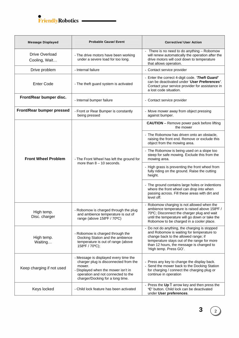
Message Displayed
Probable Cause/Event
Corrective/User Action
Drive Overload Cooling, Wait…
- The drive motors have been working under a severe load for too long.
- There is no need to do anything – Robomow will renew automatically the operation after the drive motors will cool down to temperature that allows operation.
Drive problem - Internal failure - Contact service provider
Enter Code - The theft guard system is activated
- Enter the correct 4-digit code. ‘Theft Guard’ can be deactivated under ‘User Preferences’. Contact your service provider for assistance in a lost code situation.
Front/Rear bumper disc.
- Internal bumper failure - Contact service provider
Front/Rear bumper pressed
- Front or Rear Bumper is constantly being pressed
- Move mower away from object pressing against bumper.
CAUTION – Remove power pack before lifting the mower
- The Robomow has driven onto an obstacle, raising the front end. Remove or exclude this object from the mowing area.
- The Robomow is being used on a slope too steep for safe mowing. Exclude this from the mowing area.
- High grass is preventing the front wheel from fully riding on the ground. Raise the cutting height.
Front Wheel Problem
- The Front Wheel has left the ground for more than 8 – 10 seconds.
- The ground contains large holes or indentions where the front wheel can drop into when passing across. Fill these areas with dirt and level off.
High temp. Disc. charger
- Robomow is charged through the plug and ambience temperature is out of range (above 158ºF / 70ºC)
- Robomow charging is not allowed when the ambience temperature is raised above 158ºF / 70ºC; Disconnect the charger plug and wait until the temperature will go down or take the Robomow to be charged in a cooler place.
High temp. Waiting…
- Robomow is charged through the Docking Station and the ambience temperature is out of range (above 158ºF / 70ºC);
- Do not do anything, the charging is stopped and Robomow is waiting for temperature to change back to the allowed range; if temperature stays out of the range for more than 12 hours, the message is changed to ‘High temp. Press GO’.
Keep charging if not used
- Message is displayed every time the charger plug is disconnected from the mower.
- Displayed when the mower isn’t in operation and not connected to the charger/Docking for a long time.
- Press any key to change the display back. - Send the mower back to the Docking Station
for charging / connect the charging plug or continue in operation
Keys locked - Child lock feature has been activated - Press the Up ⇑ arrow key and then press the
‘C’ button. Child lock can be deactivated under User preferences.
2
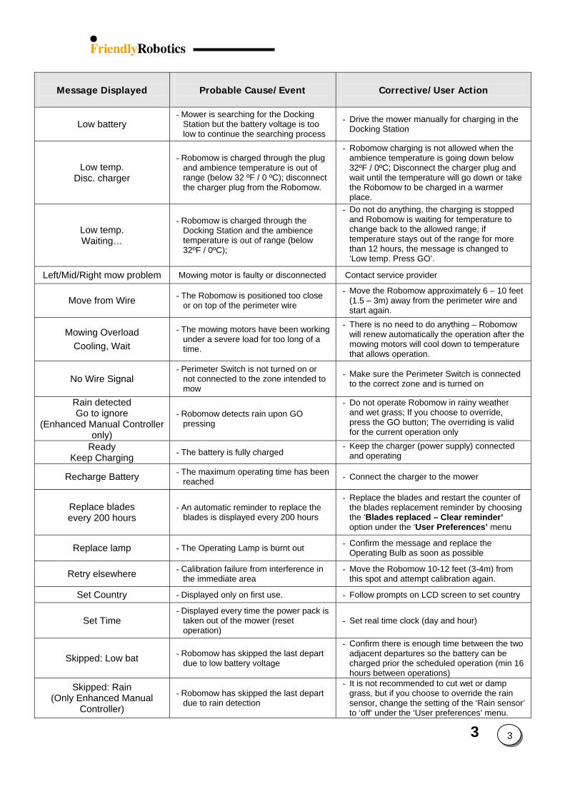
3 3
Message Displayed
Probable Cause/Event
Corrective/User Action
Low battery - Mower is searching for the Docking
Station but the battery voltage is too low to continue the searching process
- Drive the mower manually for charging in the Docking Station
Low temp. Disc. charger
- Robomow is charged through the plug and ambience temperature is out of range (below 32 ºF / 0 ºC); disconnect the charger plug from the Robomow.
- Robomow charging is not allowed when the ambience temperature is going down below 32ºF / 0ºC; Disconnect the charger plug and wait until the temperature will go down or take the Robomow to be charged in a warmer place.
Low temp. Waiting…
- Robomow is charged through the Docking Station and the ambience temperature is out of range (below 32ºF / 0ºC);
- Do not do anything, the charging is stopped and Robomow is waiting for temperature to change back to the allowed range; if temperature stays out of the range for more than 12 hours, the message is changed to ‘Low temp. Press GO’.
Left/Mid/Right mow problem Mowing motor is faulty or disconnected Contact service provider
Move from Wire - The Robomow is positioned too close or on top of the perimeter wire
- Move the Robomow approximately 6 – 10 feet (1.5 – 3m) away from the perimeter wire and start again.
Mowing Overload Cooling, Wait
- The mowing motors have been working under a severe load for too long of a time.
- There is no need to do anything – Robomow will renew automatically the operation after the mowing motors will cool down to temperature that allows operation.
No Wire Signal - Perimeter Switch is not turned on or
not connected to the zone intended to mow
- Make sure the Perimeter Switch is connected to the correct zone and is turned on
Rain detected Go to ignore
(Enhanced Manual Controller only)
- Robomow detects rain upon GO pressing
- Do not operate Robomow in rainy weather and wet grass; If you choose to override, press the GO button; The overriding is valid for the current operation only
Ready Keep Charging - The battery is fully charged
- Keep the charger (power supply) connected and operating
Recharge Battery - The maximum operating time has been reached - Connect the charger to the mower
Replace blades every 200 hours
- An automatic reminder to replace the blades is displayed every 200 hours
- Replace the blades and restart the counter of the blades replacement reminder by choosing the ‘Blades replaced – Clear reminder’ option under the ‘User Preferences’ menu
Replace lamp - The Operating Lamp is burnt out - Confirm the message and replace the Operating Bulb as soon as possible
Retry elsewhere - Calibration failure from interference in the immediate area
- Move the Robomow 10-12 feet (3-4m) from this spot and attempt calibration again.
Set Country - Displayed only on first use. - Follow prompts on LCD screen to set country
Set Time - Displayed every time the power pack is
taken out of the mower (reset operation)
- Set real time clock (day and hour)
Skipped: Low bat - Robomow has skipped the last depart due to low battery voltage
- Confirm there is enough time between the two adjacent departures so the battery can be charged prior the scheduled operation (min 16 hours between operations)
Skipped: Rain (Only Enhanced Manual
Controller)
- Robomow has skipped the last depart due to rain detection
- It is not recommended to cut wet or damp grass, but if you choose to override the rain sensor, change the setting of the ‘Rain sensor’ to ‘off’ under the ‘User preferences’ menu.
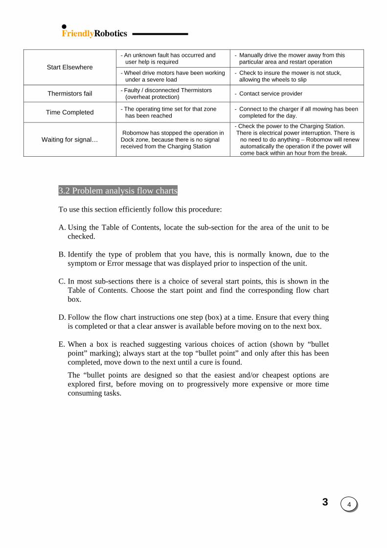
3
- An unknown fault has occurred and user help is required
- Manually drive the mower away from this particular area and restart operation
Start Elsewhere - Wheel drive motors have been working
under a severe load - Check to insure the mower is not stuck,
allowing the wheels to slip
Thermistors fail - Faulty / disconnected Thermistors (overheat protection) - Contact service provider
Time Completed - The operating time set for that zone has been reached
- Connect to the charger if all mowing has been completed for the day.
Waiting for signal… Robomow has stopped the operation in Dock zone, because there is no signal received from the Charging Station
- Check the power to the Charging Station. There is electrical power interruption. There is
no need to do anything – Robomow will renew automatically the operation if the power will come back within an hour from the break.
3.2 Problem analysis flow charts
To use this section efficiently follow this procedure: A. Using the Table of Contents, locate the sub-section for the area of the unit to be
checked. B. Identify the type of problem that you have, this is normally known, due to the
symptom or Error message that was displayed prior to inspection of the unit. C. In most sub-sections there is a choice of several start points, this is shown in the
Table of Contents. Choose the start point and find the corresponding flow chart box.
D. Follow the flow chart instructions one step (box) at a time. Ensure that every thing
is completed or that a clear answer is available before moving on to the next box. E. When a box is reached suggesting various choices of action (shown by “bullet
point” marking); always start at the top “bullet point” and only after this has been completed, move down to the next until a cure is found.
The “bullet points are designed so that the easiest and/or cheapest options are explored first, before moving on to progressively more expensive or more time consuming tasks.
4
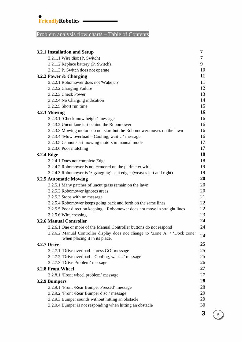
3 5
Problem analysis flow charts – Table of Contents 3.2.1 Installation and Setup 7
3.2.1.1 Wire disc (P. Switch) 7 3.2.1.2 Replace battery (P. Switch) 9 3.2.1.3 P. Switch does not operate 10
3.2.2 Power & Charging 11 3.2.2.1 Robomower does not 'Wake up' 11 3.2.2.2 Charging Failure 12 3.2.2.3 Check Power 13 3.2.2.4 No Charging indication 14 3.2.2.5 Short run time 15
3.2.3 Mowing 16 3.2.3.1 ‘Check mow height’ message 16 3.2.3.2 Uncut lane left behind the Robomower 16 3.2.3.3 Mowing motors do not start but the Robomower moves on the lawn 16 3.2.3.4 ‘Mow overload – Cooling, wait…’ message 16 3.2.3.5 Cannot start mowing motors in manual mode 17 3.2.3.6 Poor mulching 17
3.2.4 Edge 18 3.2.4.1 Does not complete Edge 18 3.2.4.2 Robomower is not centered on the perimeter wire 19 3.2.4.3 Robomower is ‘zigzagging’ as it edges (weaves left and right) 19
3.2.5 Automatic Mowing 20 3.2.5.1 Many patches of uncut grass remain on the lawn 20 3.2.5.2 Robomower ignores areas 20 3.2.5.3 Stops with no message 21 3.2.5.4 Robomower keeps going back and forth on the same lines 22 3.2.5.5 Poor direction keeping – Robomower does not move in straight lines 22 3.2.5.6 Wire crossing 23
3.2.6 Manual Controller 24 3.2.6.1 One or more of the Manual Controller buttons do not respond 24 3.2.6.2 Manual Controller display does not change to ‘Zone A’ / ‘Dock zone’
when placing it in its place. 24
3.2.7 Drive 25 3.2.7.1 ‘Drive overload – press GO’ message 25 3.2.7.2 ‘Drive overload – Cooling, wait…’ message 25 3.2.7.3 ‘Drive Problem’ message 26
3.2.8 Front Wheel 27 3.2.8.1 ‘Front wheel problem’ message 27
3.2.9 Bumpers 28 3.2.9.1 ‘Front /Rear Bumper Pressed’ message 28 3.2.9.2 ‘Front /Rear Bumper disc.’ message 29 3.2.9.3 Bumper sounds without hitting an obstacle 29 3.2.9.4 Bumper is not responding when hitting an obstacle 30
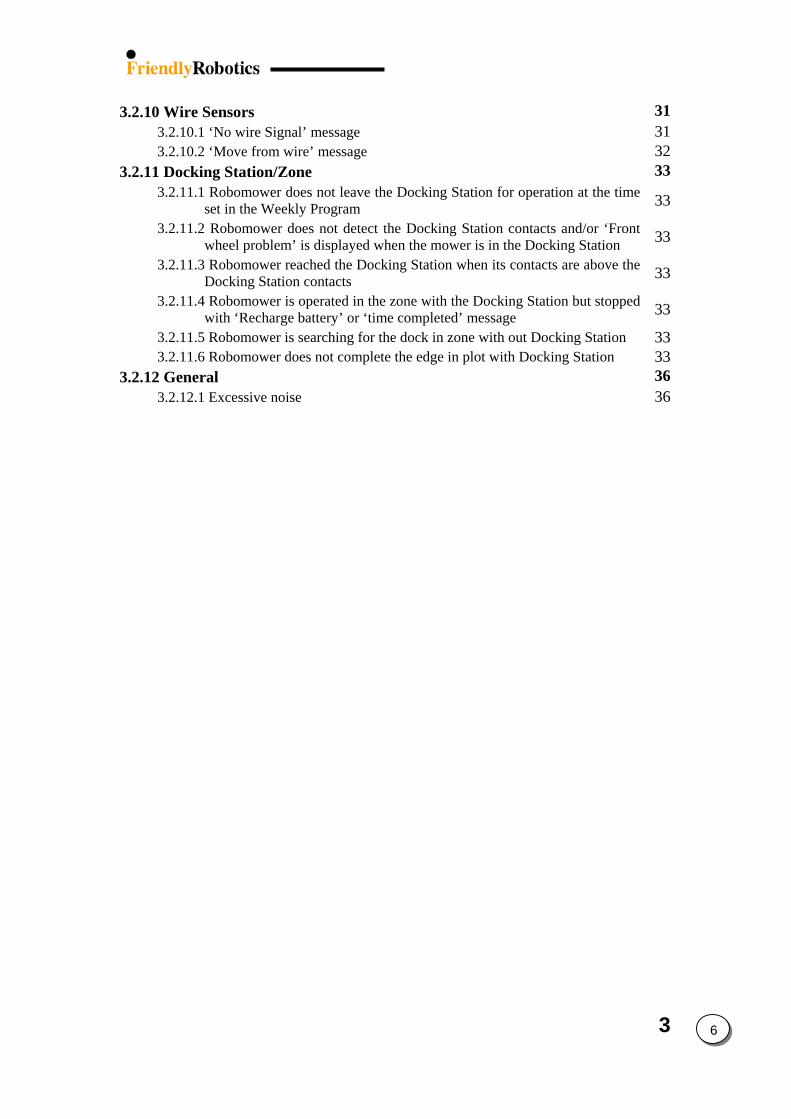
3
3.2.10 Wire Sensors 31 3.2.10.1 ‘No wire Signal’ message 31 3.2.10.2 ‘Move from wire’ message 32
3.2.11 Docking Station/Zone 33 3.2.11.1 Robomower does not leave the Docking Station for operation at the time
set in the Weekly Program 33
3.2.11.2 Robomower does not detect the Docking Station contacts and/or ‘Front wheel problem’ is displayed when the mower is in the Docking Station 33
3.2.11.3 Robomower reached the Docking Station when its contacts are above the Docking Station contacts 33
3.2.11.4 Robomower is operated in the zone with the Docking Station but stopped with ‘Recharge battery’ or ‘time completed’ message 33
3.2.11.5 Robomower is searching for the dock in zone with out Docking Station 33 3.2.11.6 Robomower does not complete the edge in plot with Docking Station 33
3.2.12 General 36 3.2.12.1 Excessive noise 36
6
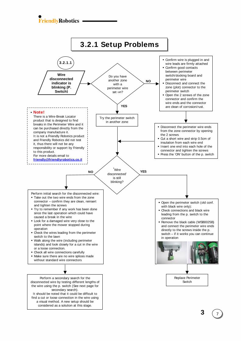
3
3.2.1 Setup Problems
7
NO
YES
Open the perimeter switch (old conf. with black wire only): Check connections and black wire leading from the p. switch to the connector Remove the black cable (WSB0025B)and connect the perimeter wire ends directly to the screws inside the p. switch – if it works you can continue in operation
Confirm wire is plugged in and wire leads are firmly attached Confirm good contacts between perimeter switch/docking board and perimeter wire Disconnect and connect the zone (plot) connector to the perimeter switch Open the 2 screws of the zone connector and confirm the wire ends and the connector are clean of corrosion/rust.
Wire disconnected indicator is blinking (P.
Switch)
Do you have another zone
with a perimeter wire
set up?
3.2.1.1
Perform initial search for the disconnected wire: Take out the two wire ends from the zone connector – confirm they are clean, reinsert and tighten the screws Try to remember if any work has been done since the last operation which could have caused a break in the wire Look for a damaged wire very close to the point where the mower stopped during operation Check the wires leading from the perimeter switch to the lawn Walk along the wire (including perimeter islands) and look closely for a cut in the wire or a loose connection. Check all wire connections carefully Make sure there are no wire splices made without standard wire connectors
‘Wire disconnected’
is still blinking?
YESNO
Note! There is a Wire-Break Locator product that is designed to find breaks in the Perimeter Wire and it can be purchased directly from the company manufacture it. It is not a Friendly Robotics product and Friendly Robotics did not test it, thus there will not be any responsibility or support by Friendly to this product. For more details email to [email protected]
Try the perimeter switch in another zone
Disconnect the perimeter wire ends from the zone connector by opening the 2 screws Cut a short wire and strip 0.5cm of insulation from each wire end Insert one end into each hole of the connector and tighten the screws Press the ‘ON’ button of the p. switch
Replace Perimeter Switch
Perform a secondary search for the disconnected wire by testing different lengths of the wire using the p. switch (See next page for
secondary search). It should be noted that it could be difficult to
find a cut or loose connection in the wire using a visual method. A new setup should be considered as a solution at this stage.
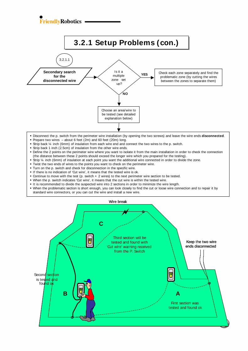
3.2.1 Setup Problems (con.)
3 8
NO
YES
Is it a multiple
zone set up?
Secondary search for the
disconnected wire
Choose an area/wire to be tested (see detailed
explanation below)
Check each zone separately and find the problematic zone (by cutting the wires between the zones to separate them)
Disconnect the p. switch from the perimeter wire installation (by opening the two screws) and leave the wire ends disconnected. Prepare two wires – about 6 feet (2m) and 60 feet (20m) long. Strip back ¼ inch (6mm) of insulation from each wire end and connect the two wires to the p. switch. Strip back 1 inch (2.5cm) of insulation from the other wire ends. Define the 2 points on the perimeter wire where you want to isolate it from the main installation in order to check the connection (the distance between these 2 points should exceed the longer wire which you prepared for the testing). Strip ¼ inch (6mm) of insulation at each point you want the additional wire connected in order to divide the zone. Twist the two ends of wires to the points you want to check on the perimeter wire. Turn on the p. switch and check for disconnection in the specific wire. If there is no indication of ‘Cut wire’, it means that the tested wire is ok. Continue to move with the test (p. switch + 2 wires) to the next perimeter wire section to be tested. When the p. switch indicates ‘Cut wire’, it means that the cut wire is within the tested wire. It is recommended to divide the suspected wire into 2 sections in order to minimize the wire length. When the problematic section is short enough, you can look closely to find the cut or loose wire connection and to repair it by standard wire connectors, or you can cut the wire and install a new wire.
3.2.1.1
Keep the two wire ends disconnected
Wire break
First section wastested and found ok
Third section will betested and found with
‘Cut wire’ warning received from the P. Switch
A B
C
A
First section wastested and found ok
Wire break
Keep the two wire ends disconnected
Second section
B
is tested and found ok
Third section will betested and found with
‘Cut wire’ warning received
C
from the P. Switch
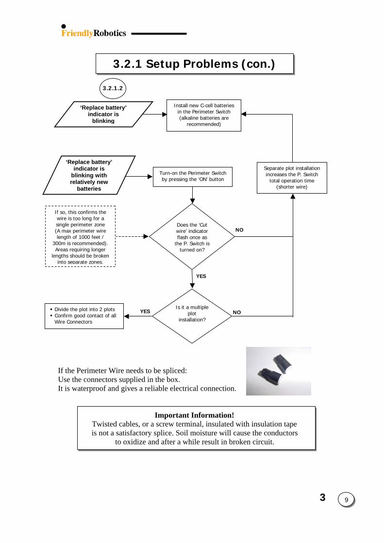
3
3.2.1 Setup Problems (con.)
9
‘Replace battery’ indicator is
blinking
Install new C-cell batteries in the Perimeter Switch (alkaline batteries are
recommended)
YES
NO
‘Replace battery’ indicator is
blinking with relatively new
batteries
Turn-on the Perimeter Switch by pressing the ‘ON’ button
If so, this confirms the wire is too long for a single perimeter zone (A max perimeter wire length of 1000 feet /
300m is recommended). Areas requiring longer
lengths should be broken into separate zones.
Does the ‘Cut wire’ indicator flash once as
the P. Switch is turned on?
Separate plot installation increases the P. Switch
total operation time (shorter wire)
3.2.1.2
Is it a multiple plot
installation?
YES NO Divide the plot into 2 plots Confirm good contact of all Wire Connectors
If the Perimeter Wire needs to be spliced: Use the connectors supplied in the box. It is waterproof and gives a reliable electrical connection.
Important Information! Twisted cables, or a screw terminal, insulated with insulation tape is not a satisfactory splice. Soil moisture will cause the conductors
to oxidize and after a while result in broken circuit.
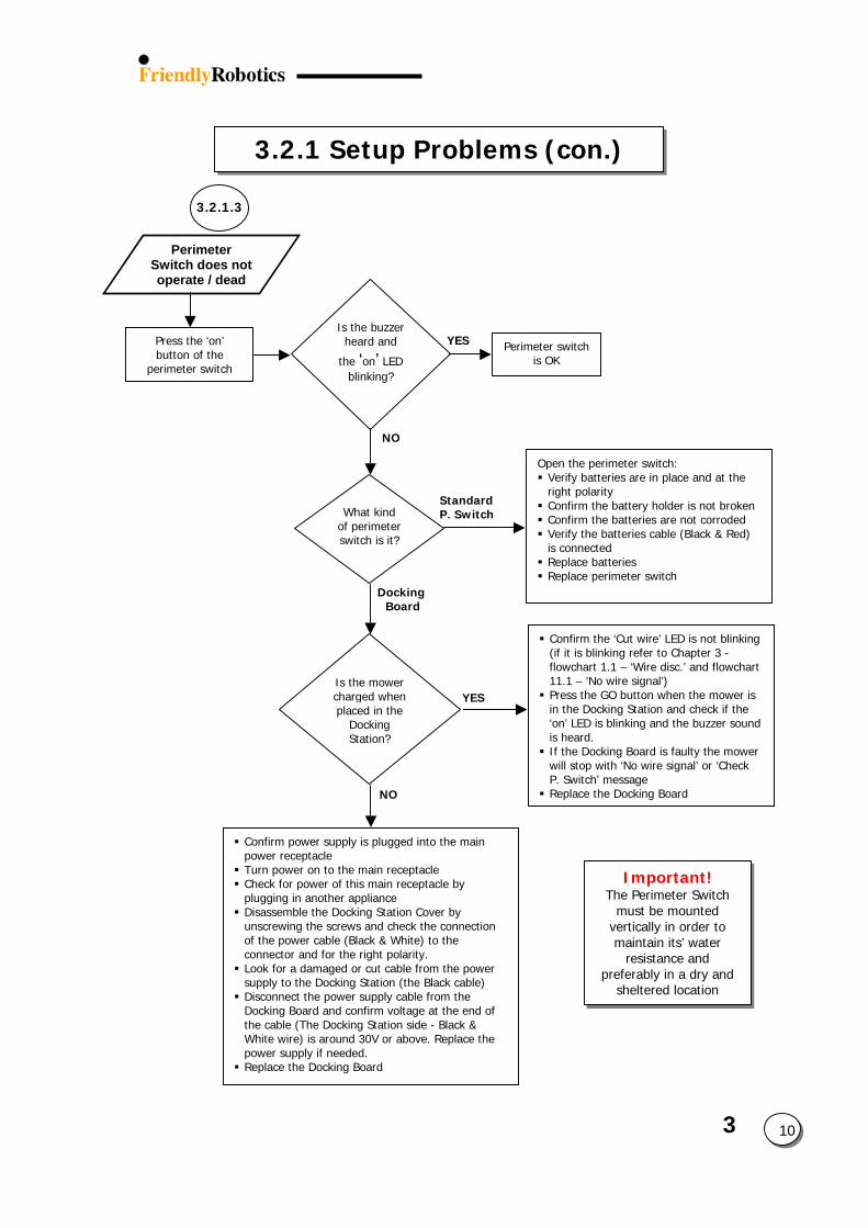
3.2.1 Setup Problems (con.) YES NO
Docking Board
NO
Perimeter switch is OK
Open the perimeter switch: Verify batteries are in place and at the right polarity
What kind of perimeter switch is it?
Is the mower charged when placed in the
Docking Station?
Confirm power supply is plugged intopower receptacle Turn power on to the main receptacl Check for power of this main receptaplugging in another appliance Disassemble the Docking Station Covunscrewing the screws and check theof the power cable (Black & White) tconnector and for the right polarity. Look for a damaged or cut cable fromsupply to the Docking Station (the Bl Disconnect the power supply cable frDocking Board and confirm voltage athe cable (The Docking Station side White wire) is around 30V or above.power supply if needed. Replace the Docking Board
Perimeter Switch does not operate / dead
3.2.1.3
Press the ‘on’ button of the
perimeter switch
Is the buzzer heard and
the ‘on’ LED blinking?
3Standard P. Switch
YES
10
Important! The Perimeter Switch
must be mounted vertically in order to maintain its’ water
resistance and preferably in a dry and
sheltered location
Confirm the battery holder is not broken Confirm the batteries are not corroded Verify the batteries cable (Black & Red) is connected Replace batteries Replace perimeter switch
the main
e cle by
er by connection
o the
the power ack cable) om the t the end of
- Black & Replace the
Confirm the ‘Cut wire’ LED is not blinking (if it is blinking refer to Chapter 3 - flowchart 1.1 – ‘Wire disc.’ and flowchart 11.1 – ‘No wire signal’) Press the GO button when the mower is in the Docking Station and check if the ‘on’ LED is blinking and the buzzer sound is heard. If the Docking Board is faulty the mower will stop with ‘No wire signal’ or ‘Check P. Switch’ message Replace the Docking Board
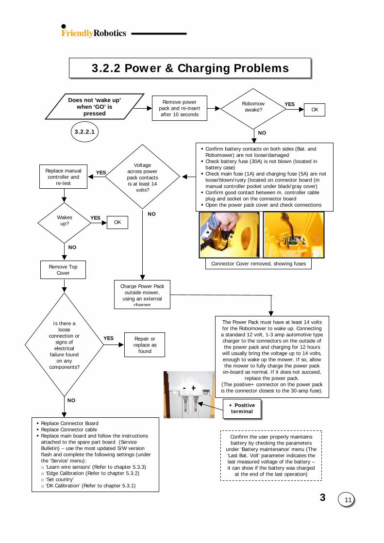
3
3.2.2 Power & Charging Problems
11
Remove Top Cover
NO
Confirm the user properly maintains battery by checking the parameters
under ‘Battery maintenance’ menu (The ‘Last Bat. Volt’ parameter indicates the last measured voltage of the battery – it can show if the battery was charged
at the end of the last operation)
+-
+ Positiveterminal
Connector Cover removed, showing fuses
Remove power pack and re-insert after 10 seconds
Robomow awake?
NO
OKYES
Confirm battery contacts on both sides (Bat. and Robomower) are not loose/damaged Check battery fuse (30A) is not blown (located in battery case) Check main fuse (1A) and charging fuse (5A) are not loose/blown/rusty (located on connector board (in manual controller pocket under black/gray cover) Confirm good contact between m. controller cable plug and socket on the connector board Open the power pack cover and check connections
The Power Pack must have at least 14 volts for the Robomower to wake up. Connecting a standard 12 volt, 1-3 amp automotive type charger to the connectors on the outside of the power pack and charging for 12 hours
will usually bring the voltage up to 14 volts, enough to wake up the mower. If so, allow the mower to fully charge the power pack on-board as normal. If it does not succeed,
replace the power pack. (The positive+ connector on the power pack is the connector closest to the 30-amp fuse).
Does not ‘wake up’ when ‘GO’ is
pressed
3.2.2.1
YESVoltage
across power pack contacts is at least 14
volts?
Replace manual controller and
re-test
YESWakes up?
NO
OK
Charge Power Pack outside mower,
using an external charger
NO
YES Repair or replace as
found
Is there a loose
connection or signs of electrical
failure found on any
components?
Replace Connector Board Replace Connector cable Replace main board and follow the instructions attached to the spare part board (Service Bulletin) – use the most updated S/W version flash and complete the following settings (under the ‘Service’ menu): o ‘Learn wire sensors’ (Refer to chapter 5.3.3) o ‘Edge Calibration (Refer to chapter 5.3.2) o ‘Set country’ o ‘DK Calibration’ (Refer to chapter 5.3.1)
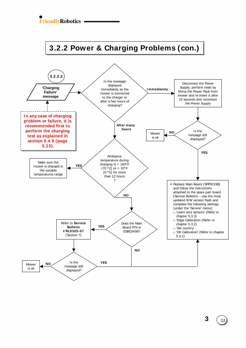
3
3.2.2 Power & Charging Problems (con.)
12
3.2.2.2
‘Charging Failure’
message
Refer to Service Bulletin
#RL0305-07 (Section 7)
Mower is ok
Ambiance temperature during charging is > 160ºF (70 ºC) or < 32ºF (0 ºC) for more than 12 hours
?
NO
YESMake sure the
mower is charged in the suitable
temperatures range
YESDoes the Main Board P/N is ESBC045B?
NO Is the message still displayed?
After many hours
Immediately
Is the message displayed
immediately as the mower is connected
to the charger or after a few hours of
charging?
NO
Is the message still displayed?
YESNOMower is ok
Replace Main Board (SPP0019B) and follow the instructions attached to the spare part board (Service Bulletin) – use the most updated S/W version flash and complete the following settings (under the ‘Service’ menu): o ‘Learn wire sensors’ (Refer to
chapter 5.3.3) o ‘Edge Calibration (Refer to
chapter 5.3.2) o ‘Set country’ o ‘DK Calibration’ (Refer to chapter
5.3.1)
Disconnect the Power Supply, perform reset by
lifting the Power Pack from mower and re-insert it after 10 seconds and reconnect
the Power Supply
In any case of charging problem or failure, it is recommended first to perform the charging test as explained in section 5.4.9 (page
5.13). YES
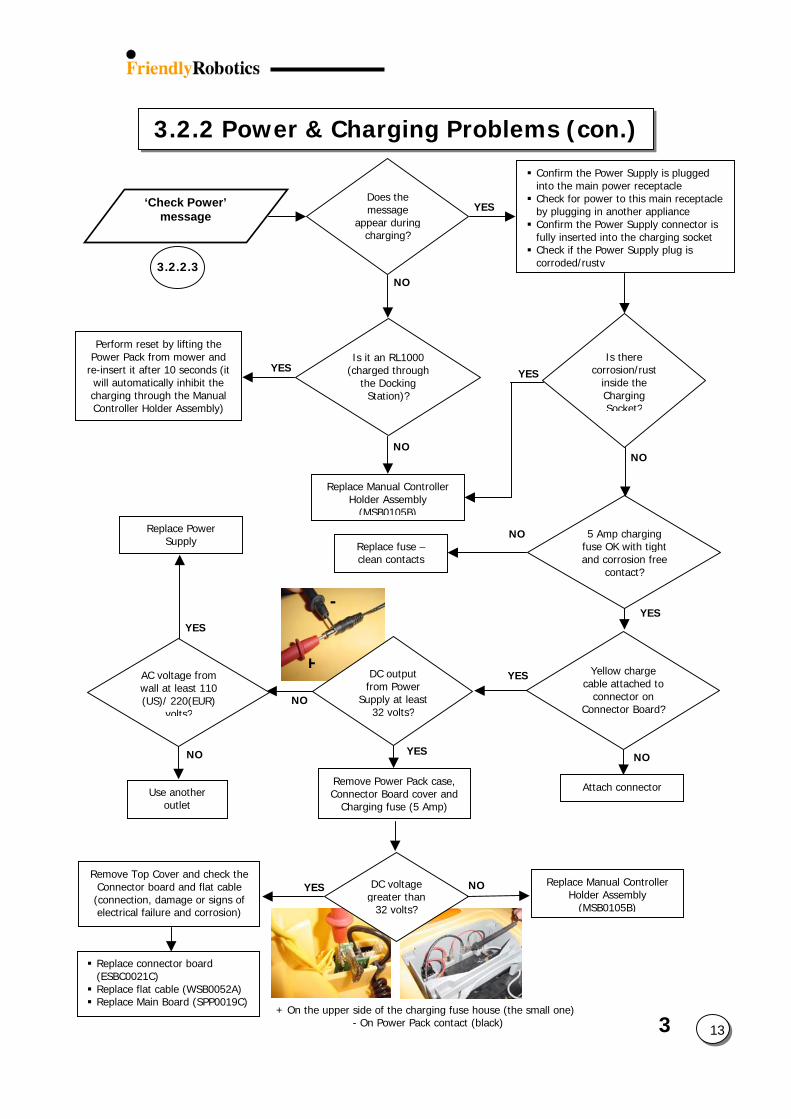
3
13
3.2.2 Power & Charging Problems (con.)
+
-
‘Check Power’ message
Does the message
appear during charging?
Perform reset by lifting the Power Pack from mower and
re-insert it after 10 seconds (it will automatically inhibit the charging through the Manual Controller Holder Assembly)
YES
NO
YES
Is it an RL1000 (charged through
the Docking Station)?
Replace fuse – clean contacts
YES
NO
NO
YES
NO
AC voltage from wall at least 110 (US)/ 220(EUR)
volts?
Replace Manual Controller Holder Assembly
(MSB0105B)
YES
YES
DC output from Power
Supply at least 32 volts?
Yellow charge cable attached to
connector on Connector Board?
5 Amp charging fuse OK with tight and corrosion free
contact?
NO
YESIs there
corrosion/rust inside the Charging Socket?
Confirm the Power Supply is plugged into the main power receptacle Check for power to this main receptacle by plugging in another appliance Confirm the Power Supply connector is fully inserted into the charging socket Check if the Power Supply plug is corroded/rusty
Remove Power Pack case, Connector Board cover and
Charging fuse (5 Amp)
3.2.2.3
Replace Power Supply
NO
NO
Attach connectorUse another outlet
YES DC voltage greater than
32 volts?
+ On the upper side of the charging fuse house (the small one) - On Power Pack contact (black)
NO Replace Manual Controller Holder Assembly
(MSB0105B)
Replace connector board (ESBC0021C) Replace flat cable (WSB0052A) Replace Main Board (SPP0019C)
Remove Top Cover and check the Connector board and flat cable (connection, damage or signs of electrical failure and corrosion)
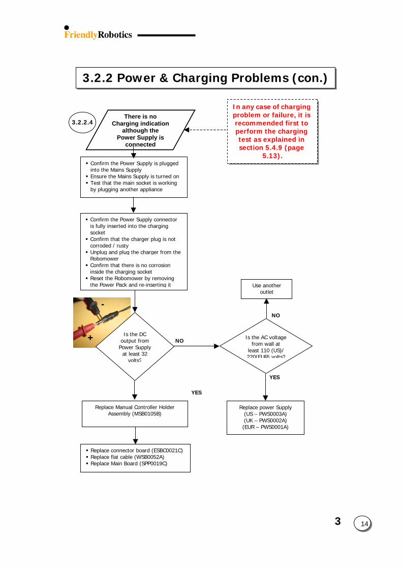
3
3.2.2 Power & Charging Problems (con.)
14
+
-
There is no Charging indication
although the Power Supply is
connected
In any case of charging problem or failure, it is recommended first to perform the charging test as explained in section 5.4.9 (page
5.13).
3.2.2.4
Confirm the Power Supply is plugged into the Mains Supply Ensure the Mains Supply is turned on Test that the main socket is working by plugging another appliance
Confirm the Power Supply connector is fully inserted into the charging socket Confirm that the charger plug is not corroded / rusty Unplug and plug the charger from the Robomower Confirm that there is no corrosion inside the charging socket Reset the Robomower by removing the Power Pack and re-inserting it
YES
NO
Is the AC voltage from wall at
least 110 (US)/ 220(EUR) volts?
Is the DC output from
Power Supply at least 32
volts?
Replace connector board (ESBC0021C) Replace flat cable (WSB0052A) Replace Main Board (SPP0019C)
Replace power Supply (US – PWS0003A) (UK – PWS0002A) (EUR – PWS0001A)
Replace Manual Controller Holder Assembly (MSB0105B)
Use another outlet
NO YES
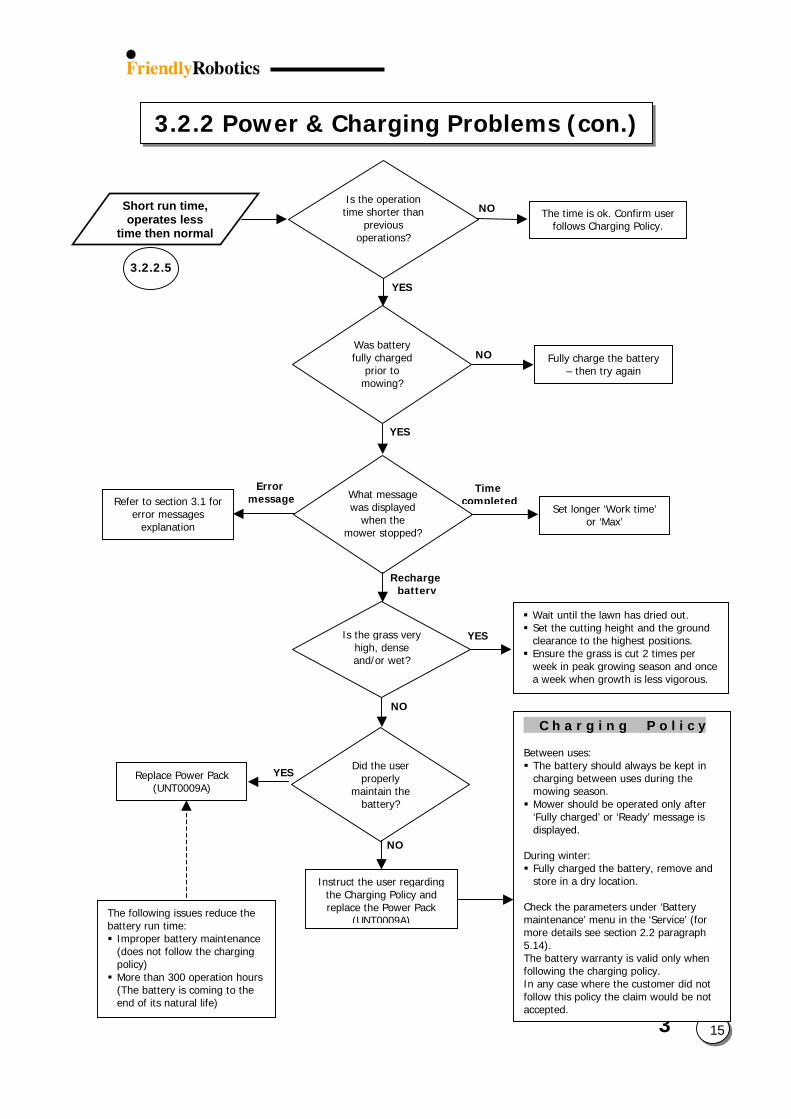
3.2.2 Power & Charging Problems (con.)
3.2.2.5
Short run time, operates less
time then normal The time is ok. Confirm user
follows Charging Policy.
The following issues reduce the battery run time: Improper battery maintenance (does not follow the charging policy) More than 300 operation hours (The battery is coming to the end of its natural life)
YES
YES
Error message
NO
Timecomple
Is the operation time shorter than
previous operations?
NO
NO
YES
Was battery fully charged
prior to mowing?
Fully charge the battery – then try again
Rechargebattery
Is the grass very high, dense and/or wet?
NO
YES
Instruct the user regarding the Charging Policy and replace the Power Pack
(UNT0009A)
Did the user properly
maintain the battery?
Replace Power Pack (UNT0009A)
Refer to section 3.1 for error messages
explanation
What message was displayed
when the mower stopped?
ted
Set longer ‘Work time’ or ‘Max’
3
15
Wait until the lawn has dried out. Set the cutting height and the ground clearance to the highest positions. Ensure the grass is cut 2 times per week in peak growing season and once a week when growth is less vigorous.
C h a r g i n g P o l i c y Between uses: The battery should always be kept in charging between uses during the mowing season. Mower should be operated only after ‘Fully charged’ or ‘Ready’ message is displayed.
During winter: Fully charged the battery, remove and store in a dry location.
Check the parameters under ‘Battery maintenance’ menu in the ‘Service’ (for more details see section 2.2 paragraph 5.14). The battery warranty is valid only when following the charging policy. In any case where the customer did not follow this policy the claim would be not accepted.
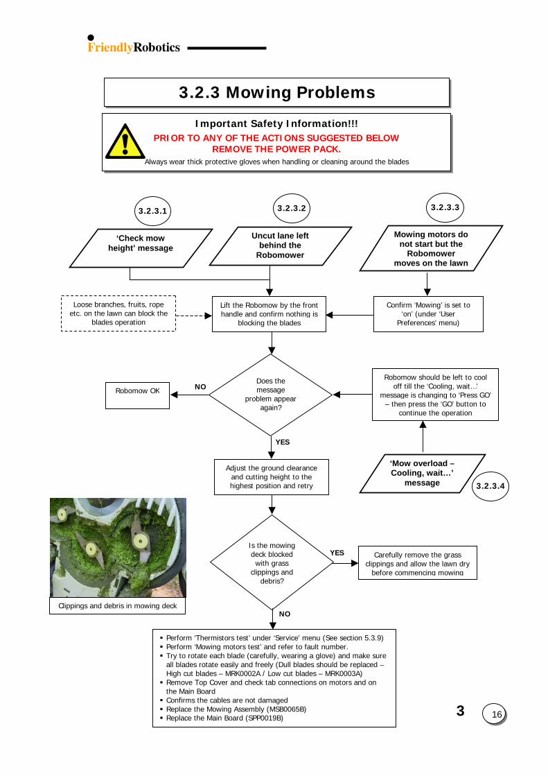
3
16
3.2.3 Mowing Problems
Important Safety Information!!! PRIOR TO ANY OF THE ACTIONS SUGGESTED BELOW
REMOVE THE POWER PACK. Always wear thick protective gloves when handling or cleaning around the blades
3.2.3.3
‘Check mow height’ message
Confirm ‘Mowing’ is set to ‘on’ (under ‘User
Preferences’ menu)
YES
Is the mowing deck blocked with grass
clippings and debris?
NODoes the message
problem appear again?
Robomow OK
Uncut lane left behind the
Robomower
Mowing motors do not start but the
Robomower moves on the lawn
Lift the Robomow by the front handle and confirm nothing is
blocking the blades
Robomow should be left to cool off till the ‘Cooling, wait…’
message is changing to ‘Press GO’ – then press the ‘GO’ button to
continue the operation
3.2.3.4
‘Mow overload –Cooling, wait…’
message
NO
YES Carefully remove the grass clippings and allow the lawn dry
before commencing mowing
Clippings and debris in mowing deck
Perform ‘Thermistors test’ under ‘Service’ menu (See section 5.3.9) Perform ‘Mowing motors test’ and refer to fault number. Try to rotate each blade (carefully, wearing a glove) and make sure all blades rotate easily and freely (Dull blades should be replaced – High cut blades – MRK0002A / Low cut blades – MRK0003A) Remove Top Cover and check tab connections on motors and on the Main Board Confirms the cables are not damaged Replace the Mowing Assembly (MSB0065B) Replace the Main Board (SPP0019B)
Loose branches, fruits, rope etc. on the lawn can block the
blades operation
Adjust the ground clearance and cutting height to the highest position and retry
3.2.3.23.2.3.1
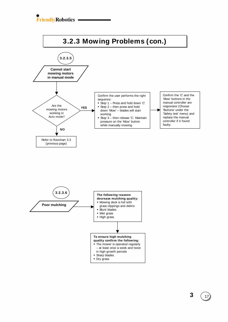
3
3.2.3 Mowing Problems (con.)
3.2.3.5
3.2.3.6
YES
NO
Are the mowing motors
working in Auto mode?
Confirm the user performs the right sequence: Step 1 – Press and hold down ‘C’ Step 2 – then press and hold down ‘Mow’ – blades will start working Step 3 – then release ‘C’. Maintain pressure on the ‘Mow’ button while manually mowing
Poor mulching
The following reasons decrease mulching quality: Mowing deck is full with grass clippings and debris Blunt blades Wet grass High grass
Refer to flowchart 3.3 (previous page)
To ensure high mulching quality confirm the following: The mower is operated regularly – at least once a week and twice in high growth periods Sharp blades Dry grass
Confirm the ‘C’ and the ‘Mow’ buttons in the manual controller are responsive (Choose ‘Buttons’ under the ‘Safety test’ menu) and replace the manual controller if it found faulty.
Cannot start mowing motors in manual mode
17
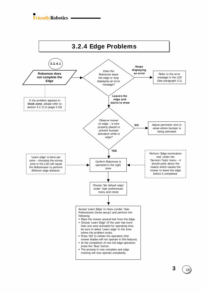
3.2.4 Edge Problems
If the problem appears in Dock zone, please refer to section 3.2.11.6 (page 3.33)
3.2.4.1
Robomow does not complete the
Edge
YES
NO
Stopdisplay
an errDoes the
Robomow leave the edge or stop
displaying an error message?
Confirm Robomow is operated in the right
zone
Choose ‘Set default edge’ under ‘User preferences’
menu and retest
‘Learn edge’ is done per zone – choosing the wrong zone in the LCD will cause the Robomower to perform
different edge distance.
Observe mower on edge – is wire properly placed to prevent bumper
activation while in edge?
Leaves theedge and
starts to mow
Access ‘Learn Edge’ in menu (under ‘User Preferences>Zones setup’) and perform the following: Place the mower several feet from the Edge Choose ‘Learn Edge’ (if the user has more than one zone activated for operating time, be sure to select ‘Learn edge’ in the zone where the problem exists. Press ‘GO’ to initiate the operation (the mower blades will not operate in this feature). At the completion of one full edge operation, press the ‘Stop’ button. The process in now complete and edge mowing will now operate completely.
s
Refer to the error message in the LCD(See paragraph 3.1)
ing or
3
18
Adjust perimeter wire in areas where bumper is
being activated
Perform ‘Edge termination test’ under the
‘Service>Tests’ menu – it should point about the
reason which causes the mower to leave the edge
before it completed.
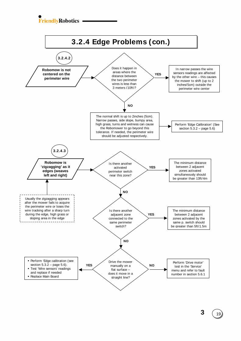
3
3.2.4 Edge Problems (con.)
19
YES
NO
In narrow passes the wire sensors readings are affected by the other wire – this causes
the mower to shift (up to 2 inches/5cm) outside the perimeter wire center
Does it happen in areas where the distance between the two perimeter wires is less than 3 meters (10ft)?
Robomow is not centered on the perimeter wire
3.2.4.2
The normal shift is up to 2inches (5cm). Narrow passes, side slope, bumpy area, high grass, turns and wetness can cause
the Robomower to go beyond this tolerance. If needed, the perimeter wire
should be adjusted respectively.
Perform ‘Edge Calibration’ (See section 5.3.2 – page 5.6)
3.2.4.3
Robomow is ‘zigzagging’ as it edges (weaves left and right)
NO
Is there another adjacent zone
connected to the same perimeter
switch?
NO
YESThe minimum distance
between 2 adjacent zones activated by the same p. switch should
be greater than 5ft/1.5m
YES Perform ‘Edge calibration (see section 5.3.2 – page 5.6). Test ‘Wire sensors’ readings and replace if needed Replace Main Board
Usually the zigzagging appears after the mower fails to acquire the perimeter wire or loses the wire tracking after a sharp turn during the edge, high grass or
sloping area in the edge
NOPerform ‘Drive motor’ test in the ‘Service’
menu and refer to fault number in section 5.6.1
Drive the mower manually on a flat surface –
does it move in a straight line?
YESThe minimum distance
between 2 adjacent zones activated
simultaneously should be greater than 13ft/4m
Is there another activated
perimeter switch near this zone?
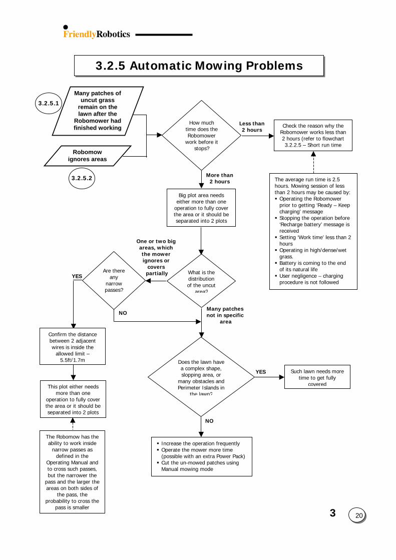
3
3.2.5 Automatic Mowing Problems
20
3.2.5.2
Robomow ignores areas
Less than 2 hours
How much time does the Robomower
work before it stops?
One or two big areas, which the mower ignores or
covers partially
NO
YES
NO
Big plot area needs either more than one
operation to fully cover the area or it should be separated into 2 plots
The average run time is 2.5 hours. Mowing session of less than 2 hours may be caused by: Operating the Robomower prior to getting ‘Ready – Keep charging’ message Stopping the operation before ‘Recharge battery’ message is received Setting ‘Work time’ less than 2 hours Operating in high/dense/wet grass. Battery is coming to the end of its natural life User negligence – charging procedure is not followed
Many patches not in specific
area
What is the distribution of the uncut
area?
Confirm the distance between 2 adjacent wires is inside the
allowed limit – 5.5ft/1.7m Does the lawn have
a complex shape, slopping area, or
many obstacles and Perimeter Islands in
the lawn?
YES
This plot either needs more than one
operation to fully cover the area or it should be separated into 2 plots
The Robomow has the ability to work inside
narrow passes as defined in the
Operating Manual and to cross such passes, but the narrower the
pass and the larger the areas on both sides of
the pass, the probability to cross the
pass is smaller
Increase the operation frequently Operate the mower more time (possible with an extra Power Pack) Cut the un-mowed patches using Manual mowing mode
Such lawn needs more time to get fully
covered
Are there any
narrow passes?
More than 2 hours
3.2.5.1
Many patches of uncut grass
remain on the lawn after the
Robomower had finished working Check the reason why the
Robomower works less than 2 hours (refer to flowchart 3.2.2.5 – Short run time
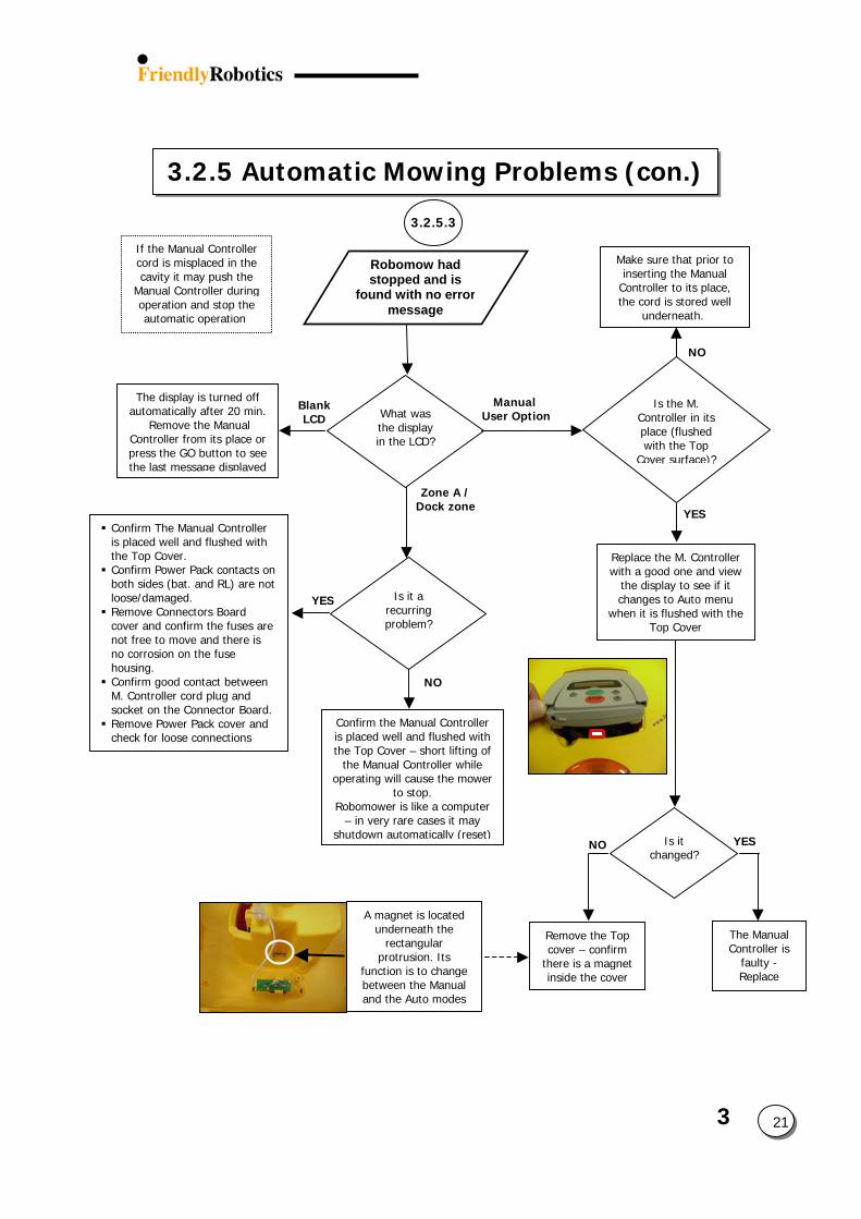
3
3.2.5 Automatic Mowing Problems (con.)
21
Robomow had stopped and is
found with no errormessage
Manual User Option
Zone A /Dock zone
What was the display in the LCD?
The display is turned off automatically after 20 min.
Remove the Manual Controller from its place or press the GO button to see the last message displayed
YES
NO
Make sure that prior to inserting the Manual
Controller to its place, the cord is stored well
underneath.
YES
NO
Confirm the Manual Controller is placed well and flushed with the Top Cover – short lifting of
the Manual Controller while operating will cause the mower
to stop. Robomower is like a computer
– in very rare cases it may shutdown automatically (reset)
Confirm The Manual Controller is placed well and flushed with the Top Cover. Confirm Power Pack contacts on both sides (bat. and RL) are not loose/damaged. Remove Connectors Board cover and confirm the fuses are not free to move and there is no corrosion on the fuse housing. Confirm good contact between M. Controller cord plug and socket on the Connector Board. Remove Power Pack cover and check for loose connections
Blank LCD
Is it a recurring problem?
Replace the M. Controller with a good one and view
the display to see if it changes to Auto menu
when it is flushed with the Top Cover
Is the M. Controller in its place (flushed with the Top
Cover surface)?
A magnet is located underneath the
rectangular protrusion. Its
function is to change between the Manual and the Auto modes
Remove the Top cover – confirm
there is a magnet inside the cover
The Manual Controller is
faulty - Replace
NO YESIs it changed?
If the Manual Controller cord is misplaced in the cavity it may push the
Manual Controller during operation and stop the automatic operation
3.2.5.3
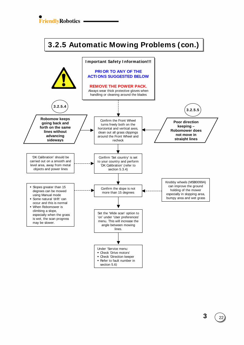
3
3.2.5 Automatic Mowing Problems (con.)
22
Robomow keeps going back and
forth on the same lines without
advancing sideways
Important Safety Information!!!
PRIOR TO ANY OF THE ACTIONS SUGGESTED BELOW
REMOVE THE POWER PACK.
Always wear thick protective gloves when handling or cleaning around the blades
Knobby wheels (MSB0099A) can improve the ground holding of the mower
especially in slopping area, bumpy area and wet grass
Confirm ‘Set country’ is set to your country and perform
‘DK Calibration’ (refer to section 5.3.4)
‘DK Calibration’ should be carried out on a smooth and level area, away from metal
objects and power lines
Confirm the slope is not more than 15 degrees
Confirm the Front Wheel turns freely both on the
horizontal and vertical axes, clean out all grass clippings around the Front Wheel and
recheck
3.2.5.43.2.5.5
Poor direction keeping –
Robomower does not move in
straight lines
Slopes greater than 15 degrees can be mowed using Manual mode Some natural ‘drift’ can occur and this is normal When Robomower is climbing a slope, especially when the grass is wet, the scan progress may be slower.
Set the ‘Wide scan’ option to ‘on’ under ‘User preferences’ menu. This will increase the
angle between mowing lines.
Under ‘Service menu: Check ‘Drive motors’ Check ‘Direction keeper Refer to fault number in section 5.6)
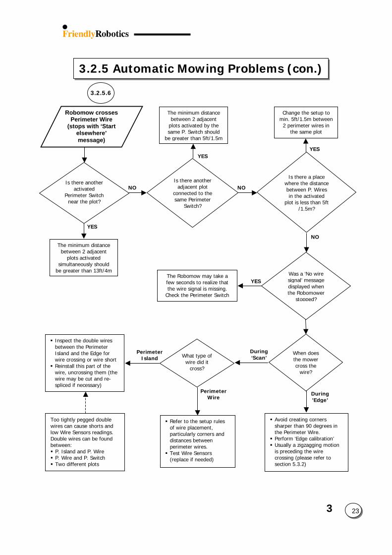
3.2.5 Automatic Mowing Problems (con.)
3.2.5.6
Is there another activated
Perimeter Switch near the plot?
Was a ‘No wire signal’ message displayed when the Robomower
stopped?
When does
the mower What type of
wire did it cross?
Robomow crosses Perimeter Wire
(stops with ‘Start elsewhere’ message)
YES
NO
YES
NO
The minimum distance between 2 adjacent
plots activated simultaneously should
be greater than 13ft/4m
Is there another adjacent plot
connected to the same Perimeter
Switch?
NO
YES
The minimum distance between 2 adjacent
plots activated by the same P. Switch should
be greater than 5ft/1.5m
Is there a place where the distance between P. Wires in the activated
plot is less than 5ft /1.5m?
Perimeter Island
Perimeter Wire
Inspect the double wires between the Perimeter Island and the Edge for wire crossing or wire short Reinstall this part of the wire, uncrossing them (the wire may be cut and re-spliced if necessary)
Too tightly pegged double wires can cause shorts and low Wire Sensors readings. Double wires can be found between: P. Island and P. Wire P. Wire and P. Switch Two different plots
Refer to the setup rules of wire placement, particularly corners and distances between perimeter wires. Test Wire Sensors (replace if needed)
YESThe Robomow may take a few seconds to realize that the wire signal is missing.
Check the Perimeter Switch
Change the setup to min. 5ft/1.5m between
2 perimeter wires in the same plot
During ‘Scan’
cross the wire?
Avoid creatingsharper than 9the Perimeter Perform ‘Edge Usually a zigzais preceding thcrossing (pleasection 5.3.2)
During
'Edge’
3 23
corners 0 degrees in Wire. calibration’ gging motion e wire
se refer to
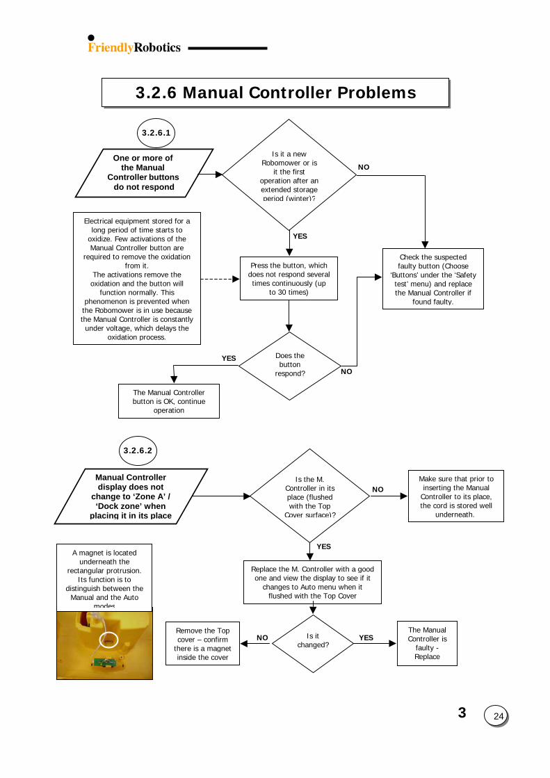
3
3.2.6 Manual Controller Problems
A magnet is located underneath the
rectangular protrusion. Its function is to
distinguish between the Manual and the Auto
modes
3.2.6.1
One or more of the Manual
Controller buttons do not respond
YES
NO
Does the button
respond?
Electrical equipment stored for a long period of time starts to
oxidize. Few activations of the Manual Controller button are
required to remove the oxidation from it.
The activations remove the oxidation and the button will
function normally. This phenomenon is prevented when
the Robomower is in use because the Manual Controller is constantly under voltage, which delays the
oxidation process.
Press the button, which does not respond several times continuously (up
to 30 times)
NO
YES
Is it a new Robomower or is
it the first operation after an extended storage period (winter)?
Check the suspected faulty button (Choose
‘Buttons’ under the ‘Safety test’ menu) and replace the Manual Controller if
found faulty.
The Manual Controller button is OK, continue
operation
3.2.6.2
Is the M. Controller in its place (flushed with the Top
Cover surface)?
YES
NO
Replace the M. Controller with a good one and view the display to see if it
changes to Auto menu when it flushed with the Top Cover
Make sure that prior to inserting the Manual
Controller to its place, the cord is stored well
underneath.
Manual Controller display does not
change to ‘Zone A’ / ‘Dock zone’ when
placing it in its place
The Manual Controller is
faulty - Replace
Remove the Top cover – confirm
there is a magnet inside the cover
Is it changed? NO YES
24
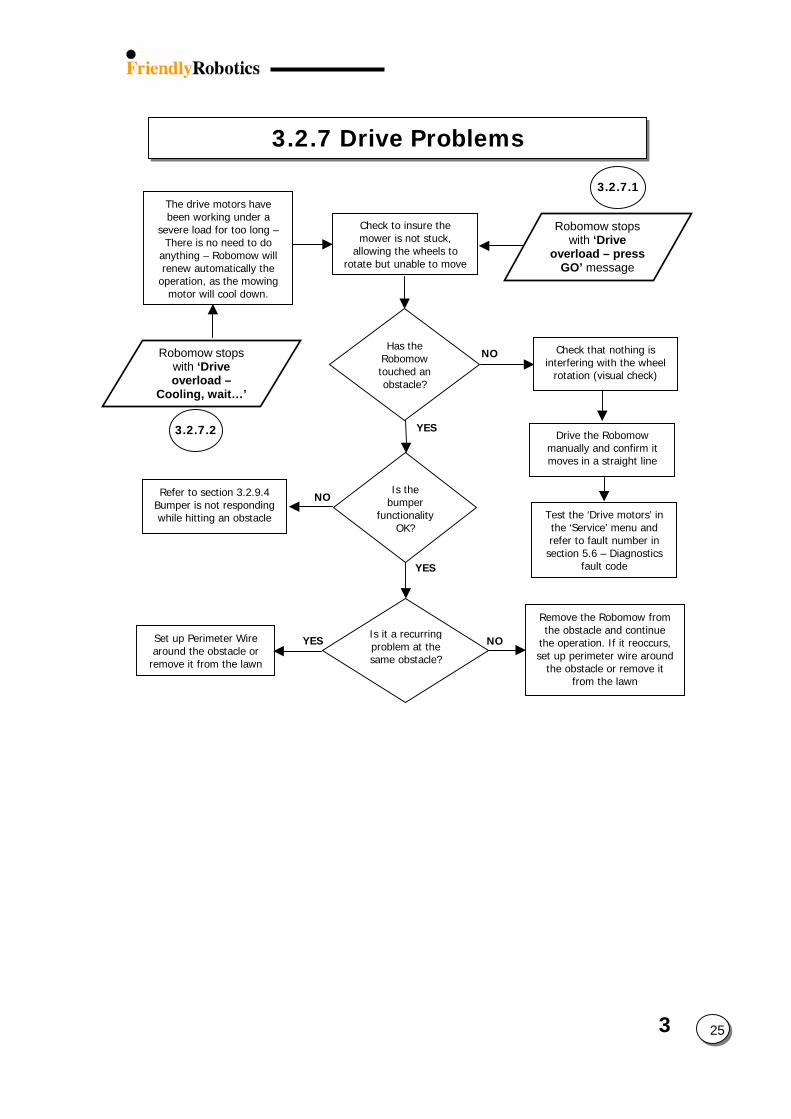
3
3.2.7 Drive Problems
25
Robomow stops with ‘Drive
overload – press GO’ message
Has the Robomow touched an obstacle?
YES
NO
YES
NOSet up Perimeter Wire around the obstacle or
remove it from the lawn
Is the bumper
functionality OK?
Refer to section 3.2.9.4 Bumper is not responding while hitting an obstacle
YES
Robomow stops with ‘Drive overload –
Cooling, wait…’
NO
Is it a recurring problem at the same obstacle?
Check to insure the mower is not stuck,
allowing the wheels to rotate but unable to move
3.2.7.2
The drive motors have been working under a
severe load for too long – There is no need to do
anything – Robomow will renew automatically the
operation, as the mowing motor will cool down.
Remove the Robomow from the obstacle and continue
the operation. If it reoccurs, set up perimeter wire around
the obstacle or remove it from the lawn
3.2.7.1
Check that nothing is interfering with the wheel
rotation (visual check)
Drive the Robomow manually and confirm it moves in a straight line
Test the ‘Drive motors’ in the ‘Service’ menu and refer to fault number in section 5.6 – Diagnostics
fault code
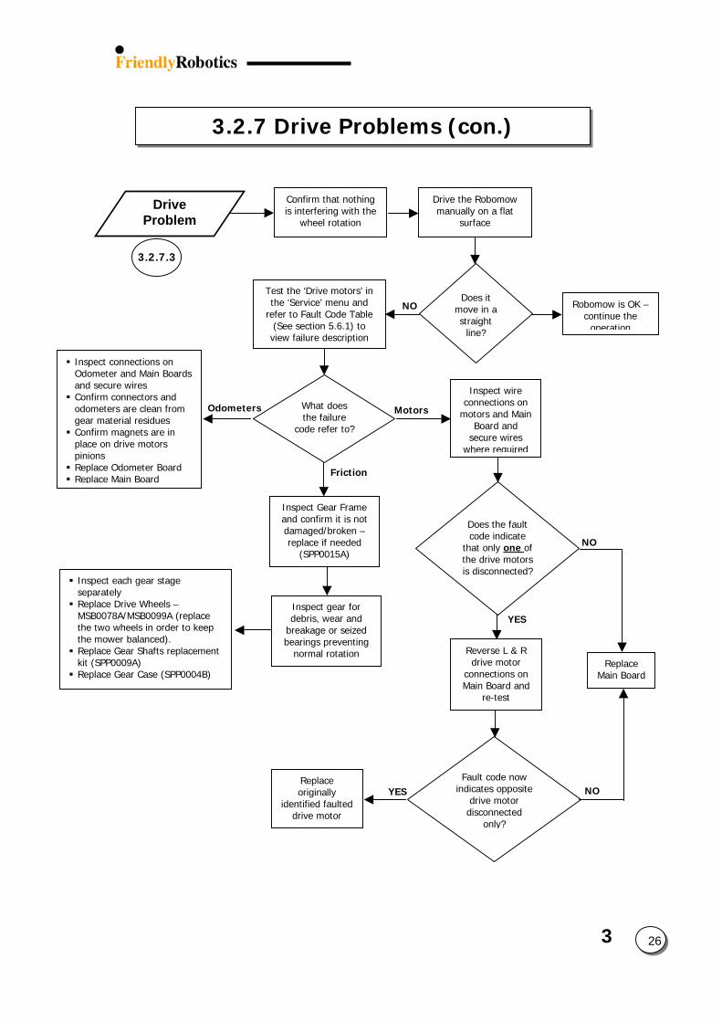
3
3.2.7 Drive Problems (con.)
26
3.2.7.3
Drive Problem
Friction
Odometers Motors
Inspect connections on Odometer and Main Boards and secure wires Confirm connectors and odometers are clean from gear material residues Confirm magnets are in place on drive motors pinions Replace Odometer Board Replace Main Board
Does it move in a straight
line?
Robomow is OK –continue the
operation
Confirm that nothing is interfering with the
wheel rotation
NO
Drive the Robomow manually on a flat
surface
Test the ‘Drive motors’ in the ‘Service’ menu and
refer to Fault Code Table (See section 5.6.1) to view failure description
What does the failure
code refer to?
Inspect wire connections on
motors and Main Board and
secure wires where required
Does the fault code indicate
that only one of the drive motors is disconnected?
NO
YES
Replace Main Board
Reverse L & R drive motor
connections on Main Board and
re-test
Fault code now indicates opposite
drive motor disconnected
only?
YES NOReplace originally
identified faulted drive motor
Inspect each gear stage separately Replace Drive Wheels – MSB0078A/MSB0099A (replace the two wheels in order to keep the mower balanced). Replace Gear Shafts replacement kit (SPP0009A) Replace Gear Case (SPP0004B)
Inspect gear for debris, wear and
breakage or seized bearings preventing
normal rotation
Inspect Gear Frame and confirm it is not damaged/broken – replace if needed
(SPP0015A)
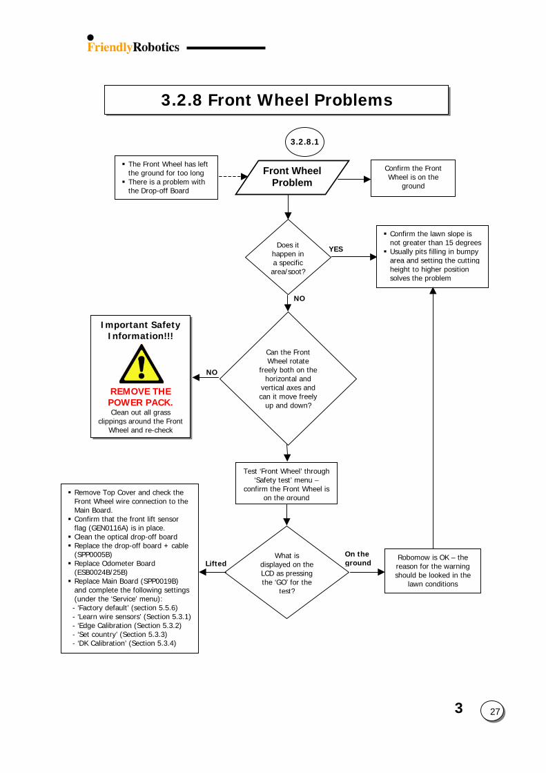
3.2.8 Front Wheel Problems
Front Wheel Problem
3.2.8.1
The Front Wheel has left the ground for too long There is a problem with the Drop-off Board
Confirm the Front Wheel is on the
ground
Important Safety Information!!!
REMOVE THE POWER PACK. Clean out all grass
clippings around the Front Wheel and re-check
Does it happen in a specific area/spot?
NO
Can the Front Wheel rotate
freely both on the horizontal and
vertical axes and can it move freely
up and down?
NO
YES
Test ‘Front Wheel’ through ‘Safety test’ menu –
confirm the Front Wheel is on the ground
Lifted
Remove Top Cover and check the Front Wheel wire connection to the Main Board. Confirm that the front lift sensor flag (GEN0116A) is in place. Clean the optical drop-off board Replace the drop-off board + cable (SPP0005B) Replace Odometer Board (ESB0024B/25B) Replace Main Board (SPP0019B) and complete the following settings (under the ‘Service’ menu):
- ‘Factory default’ (section 5.5.6) - ‘Learn wire sensors’ (Section 5.3.1) - ‘Edge Calibration (Section 5.3.2) - ‘Set country’ (Section 5.3.3) - ‘DK Calibration’ (Section 5.3.4)
On thegroun
Confirm the lawn slope is not greater than 15 degrees Usually pits filling in bumpy area and setting the cutting height to higher position solves the problem
What is displayed on the LCD as pressing the ‘GO’ for the
test?
3 27d
Robomow is OK – the reason for the warning should be looked in the
lawn conditions
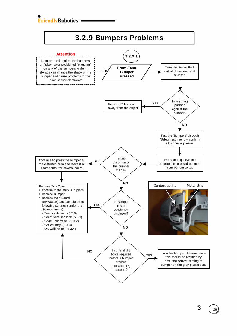
3.2.9 Bumpers Problems
Contact spring
Front /Rear Bumper Pressed
Is anything pushing
against the bumper?
Take the Power Pack out of the mower and
re-insert
NO
3.2.9.1Attention
Item pressed against the bumpers or Robomower positioned “standing”
on any of the bumpers while in storage can change the shape of the bumper and cause problems to the
touch sensor electronics
YES
Test the ‘Bumpers’ through ‘Safety test’ menu – confirm
a bumper is pressed
Is ‘Bumper pressed
constantly displayed?
Look for bumperthis should beensuring corre
bumper on the g
Remove Robomow away from the object
Press and squeeze the appropriate pressed bumper
from bottom to top
NO
NOYES
Is only slight force required
before a bumper pressed
indication (*) appears?
NO
YES
Remove Top Cover: Confirm metal strip is in place Replace Bumper Replace Main Board (SPP0019B) and complete the following settings (under the ‘Service’ menu): - ‘Factory default’ (5.5.6) - ‘Learn wire sensors’ (5.3.1) - ‘Edge Calibration’ (5.3.2) - ‘Set country’ (5.3.3) - ‘DK Calibration’ (5.3.4)
Continue to press the bumper at the distorted area and leave it at
room temp. for several hours
YESIs any
distortion of the bumper
visible?
3 28
Metal strip
deformation – rectified by ct seating of ray plastic base
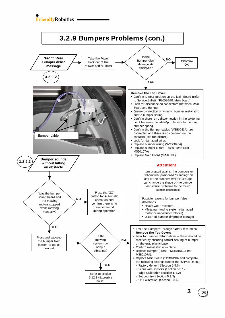
3.2.9 Bumpers Problems (con.)
YES
NO Robomow OK
Is the ‘Bumper disc.’ Message still displayed?
3.2.9.2
Take the Power Pack out of the
mower and re-insert
‘Front /Rear Bumper disc.’
message
Bumper cable
Remove the Top Cover: Confirm jumper position on the Main Board (refer to Service Bulletin ‘RL0536-01 Main Board’ Look for disconnected connectors (between Main Board and Bumper Ensure connection of wires to bumper metal strip and to bumper spring. Confirm there is no disconnection in the soldering point between the white/purple wire to the inner bumper spring Confirm the Bumper cables (WSB0043A) are connected and there is no corrosion on the contacts (see the picture) Look for damaged wires Replace bumper wiring (WSB0043A) Replace Bumper (Front – MSB0106B Rear – MSB0107A) Replace Main Board (SPP0019 )
3.2.9.3Bumper sounds without hitting
an obstacle Attention
Test the ‘Bumpers’ through ‘Remove the Top Cover: Look for bumper deformationrectified by ensuring correct on the gray plastic base. Confirm metal strip is in plac Replace Bumper (Front – MSMSB0107A). Replace Main Board (SPP001the following settings (under- ‘Factory default’ (Section 5.- ‘Learn wire sensors’ (Sectio- ‘Edge Calibration (Section 5- ‘Set country’ (Section 5.3.3- ‘DK Calibration’ (Section 5.3
Press the ‘GO’ button for Automatic
operation and confirm there is no
bumper sound during operation
Press and squeeze the bumper from bottom to top all
around
NO
YES
YES
NO
Refer to section 3.12.1 (Excessive
noise)
Is the mowing
system too noisy /
vibrating?
Was the bumper sound heard and
the mowing motors stopped while mowing
manually?
Possible reasons for bumdetections: Heavy wet / moisture Vibrating mowing systmotor or unbalanced b Distorted bumper (imp
Item pressed against thRobomower positionedany of the bumpers whcan change the shape
and cause problems sensor electro
B
3 29
!
Safety test’ menu.
s – these should be seating of bumper
e B0106B Rear –
9B) and complete the ‘Service’ menu):5.6) n 5.3.1) .3.2) ) .4)
per false
em (damaged lades) roper storage)
e bumpers or “standing” on ile in storage
of the bumper to the touch nics
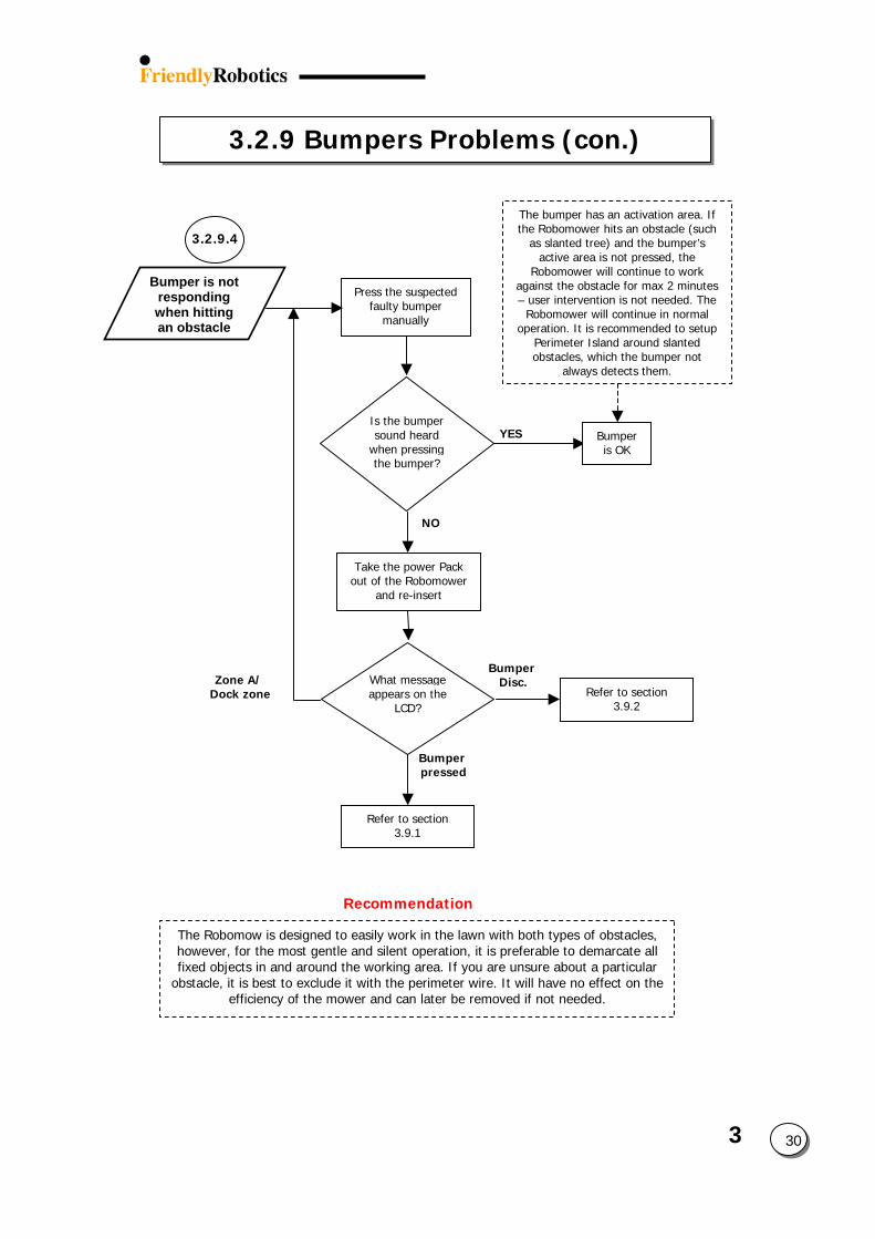
3.2.9 Bumpers Problems (con.)
Is the bumper sound heard
when pressing the bumper?
Press the suspected faulty bumper
manually
NO
YES
The bumper has an activation area. If the Robomower hits an obstacle (such
as slanted tree) and the bumper’s active area is not pressed, the
Robomower will continue to work against the obstacle for max 2 minutes – user intervention is not needed. The
Robomower will continue in normal operation. It is recommended to setup
Perimeter Island around slanted obstacles, which the bumper not
always detects them.
Bumper is OK
Take the power Pack out of the Robomower
and re-insert
Bumper Disc.
Refer to section 3.9.2
What message appears on the
LCD?
Bumper pressed
Refer to section 3.9.1
Recommendation
Bumper is not responding when hitting an obstacle
3.2.9.4
Zone A/ Dock zone
The Robomow is designed to easily work in the lahowever, for the most gentle and silent operationfixed objects in and around the working area. If y
obstacle, it is best to exclude it with the perimeter efficiency of the mower and can later be
3 30wn with both types of obstacles, , it is preferable to demarcate all ou are unsure about a particular wire. It will have no effect on the removed if not needed.
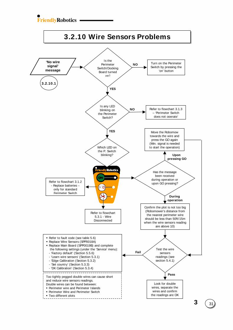
3
3.2.10 Wire Sensors Problems
31
3.2.10.1YES
Is the Perimeter
Switch/Docking Board turned
on?
‘No wire signal’
message
Turn on the Perimeter Switch by pressing the
‘on’ button
NO
Move the Robomow towards the wire and press the GO again
(Min. signal is needed to start the operation)
YES
NO Refer to flowchart 3.1.3 – ‘Perimeter Switch does not operate’
Refer to flowchart 3.1.2 - Replace batteries –
only for standard Perimeter Switch
Which LED on the P. Switch
blinking?
Refer to flowchart 5.3.1 - Wire Disconnected
Has the message been received
during operation or upon GO pressing?
During operation
Upon pressing GO
Confirm the plot is not too big (Robomower’s distance from the nearest perimeter wire
should be less than 50ft/15m when the wire sensors reading
are above 10)
Test the wire sensors
readings (see section 5.4.1)
Pass
Fail
Look for double wires, separate the wires and confirm
the readings are OK
Too tightly pegged double wires can cause short and reduce wire sensors readings. Double wires can be found between: Perimeter wire and Perimeter Islands Perimeter Wire and Perimeter Switch Two different plots
Refer to fault code (see table 5.6) Replace Wire Sensors (SPP0018A) Replace Main Board (SPP0019B) and complete the following settings (under the ‘Service’ menu):- ‘Factory default’ (Section 5.5.6) - ‘Learn wire sensors’ (Section 5.3.1) - ‘Edge Calibration (Section 5.3.2) - ‘Set country’ (Section 5.3.3) - ‘DK Calibration’ (Section 5.3.4)
Is any LED blinking on
the Perimeter Switch?
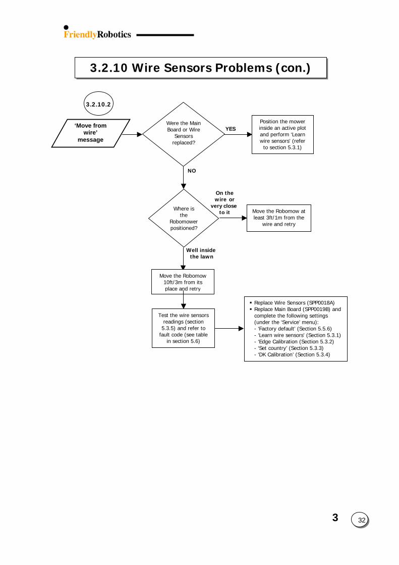
3.2.10 Wire Sensors Problems (con.)
3.2.10.2
NO
YESWere the Main Board or Wire
Sensors replaced?
‘Move from wire’
message
Position the mower
inside an active plot and perform ‘Learn wire sensors’ (refer
to section 5.3.1)
Well insidthe lawn
Where is the
Robomower positioned?
Move the Robomow 10ft/3m from its place and retry
Test the wire sensors readings (section
5.3.5) and refer to fault code (see table
in section 5.6)
On the wire or
3 32
e
very closeto it Move the Robomow at
least 3ft/1m from the wire and retry
Replace Wire Sensors (SPP0018A) Replace Main Board (SPP0019B) and complete the following settings (under the ‘Service’ menu): - ‘Factory default’ (Section 5.5.6) - ‘Learn wire sensors’ (Section 5.3.1)- ‘Edge Calibration (Section 5.3.2) - ‘Set country’ (Section 5.3.3) - ‘DK Calibration’ (Section 5.3.4)
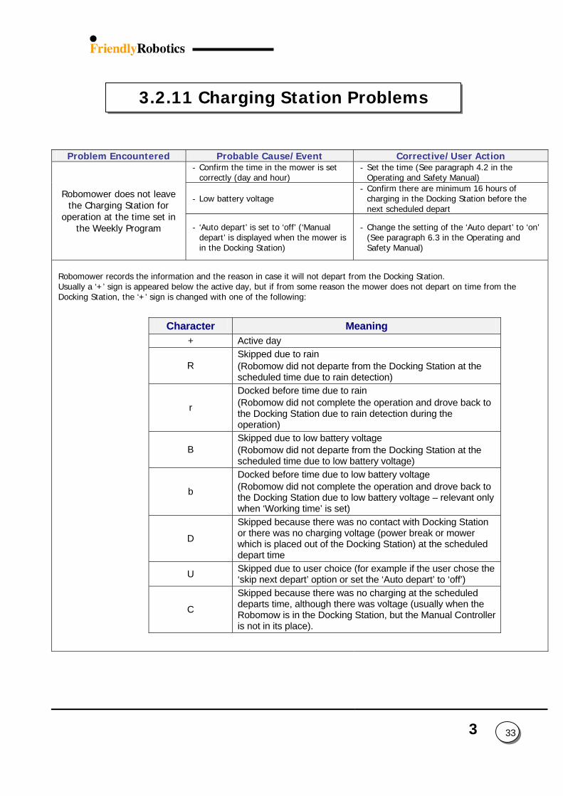
3
Character Meaning + Active day
R Skipped due to rain (Robomow did not departe from the Docking Station at the scheduled time due to rain detection)
r
Docked before time due to rain (Robomow did not complete the operation and drove back to the Docking Station due to rain detection during the operation)
B Skipped due to low battery voltage (Robomow did not departe from the Docking Station at the scheduled time due to low battery voltage)
b
Docked before time due to low battery voltage (Robomow did not complete the operation and drove back to the Docking Station due to low battery voltage – relevant only when ‘Working time’ is set)
D
Skipped because there was no contact with Docking Station or there was no charging voltage (power break or mower which is placed out of the Docking Station) at the scheduled depart time
U Skipped due to user choice (for example if the user chose the ‘skip next depart’ option or set the ‘Auto depart’ to ‘off’)
C
Skipped because there was no charging at the scheduled departs time, although there was voltage (usually when the Robomow is in the Docking Station, but the Manual Controller is not in its place).
Problem Encountered Probable Cause/Event Corrective/User Action - Confirm the time in the mower is set
correctly (day and hour) - Set the time (See paragraph 4.2 in the
Operating and Safety Manual)
- Low battery voltage - Confirm there are minimum 16 hours of
charging in the Docking Station before the next scheduled depart
Robomower does not leave the Charging Station for
operation at the time set in the Weekly Program - ‘Auto depart’ is set to ‘off’ (‘Manual
depart’ is displayed when the mower is in the Docking Station)
- Change the setting of the ‘Auto depart’ to ‘on’ (See paragraph 6.3 in the Operating and Safety Manual)
Robomower records the information and the reason in case it will not depart from the Docking Station. Usually a ‘+’ sign is appeared below the active day, but if from some reason the mower does not depart on time from the Docking Station, the ‘+’ sign is changed with one of the following:
3.2.11 Charging Station Problems
33
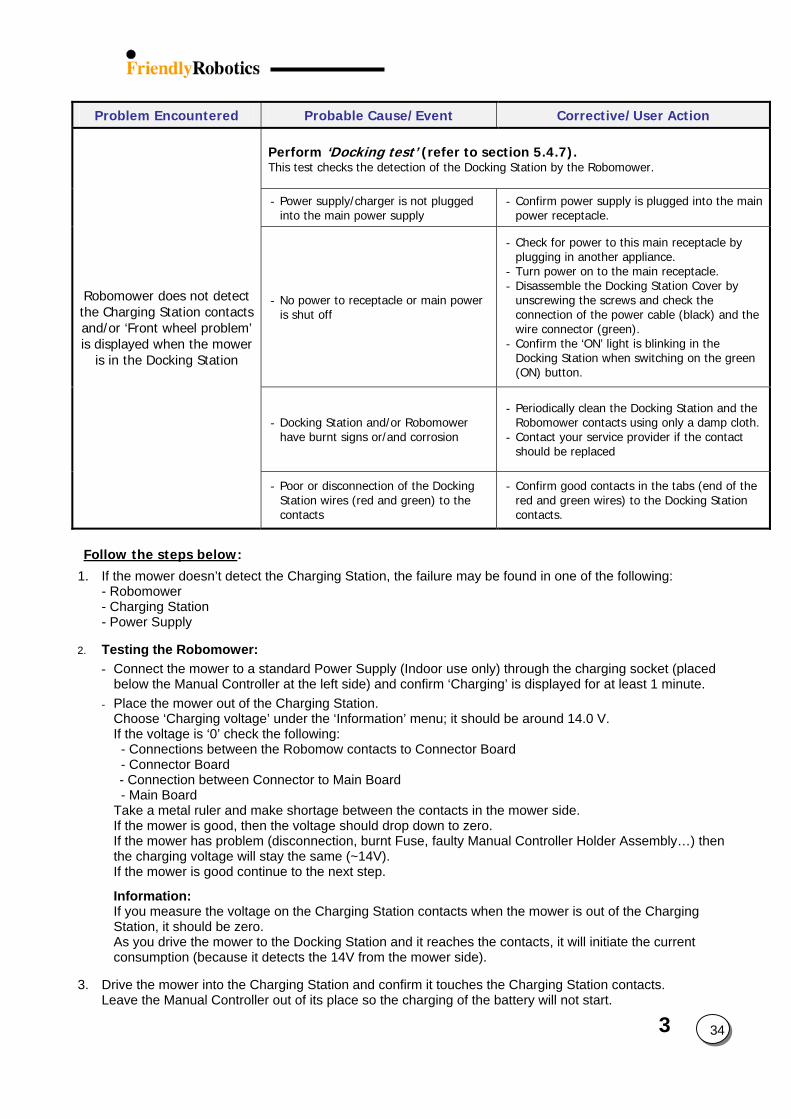
3 34
Problem Encountered Probable Cause/Event Corrective/User Action Perform ‘Docking test’ (refer to section 5.4.7). This test checks the detection of the Docking Station by the Robomower.
- Power supply/charger is not plugged into the main power supply
- Confirm power supply is plugged into the main power receptacle.
- No power to receptacle or main power is shut off
- Check for power to this main receptacle by plugging in another appliance.
- Turn power on to the main receptacle. - Disassemble the Docking Station Cover by
unscrewing the screws and check the connection of the power cable (black) and the wire connector (green).
- Confirm the ‘ON’ light is blinking in the Docking Station when switching on the green (ON) button.
- Docking Station and/or Robomower have burnt signs or/and corrosion
- Periodically clean the Docking Station and the Robomower contacts using only a damp cloth.
- Contact your service provider if the contact should be replaced
Robomower does not detect the Charging Station contacts and/or ‘Front wheel problem’ is displayed when the mower
is in the Docking Station
- Poor or disconnection of the Docking Station wires (red and green) to the contacts
- Confirm good contacts in the tabs (end of the red and green wires) to the Docking Station contacts.
Follow the steps below:
1. If the mower doesn’t detect the Charging Station, the failure may be found in one of the following: - Robomower - Charging Station - Power Supply
2. Testing the Robomower:
- Connect the mower to a standard Power Supply (Indoor use only) through the charging socket (placed below the Manual Controller at the left side) and confirm ‘Charging’ is displayed for at least 1 minute.
- Place the mower out of the Charging Station. Choose ‘Charging voltage’ under the ‘Information’ menu; it should be around 14.0 V. If the voltage is ‘0’ check the following: - Connections between the Robomow contacts to Connector Board - Connector Board - Connection between Connector to Main Board - Main Board Take a metal ruler and make shortage between the contacts in the mower side. If the mower is good, then the voltage should drop down to zero. If the mower has problem (disconnection, burnt Fuse, faulty Manual Controller Holder Assembly…) then the charging voltage will stay the same (~14V). If the mower is good continue to the next step.
Information: If you measure the voltage on the Charging Station contacts when the mower is out of the Charging Station, it should be zero. As you drive the mower to the Docking Station and it reaches the contacts, it will initiate the current consumption (because it detects the 14V from the mower side).
3. Drive the mower into the Charging Station and confirm it touches the Charging Station contacts. Leave the Manual Controller out of its place so the charging of the battery will not start.
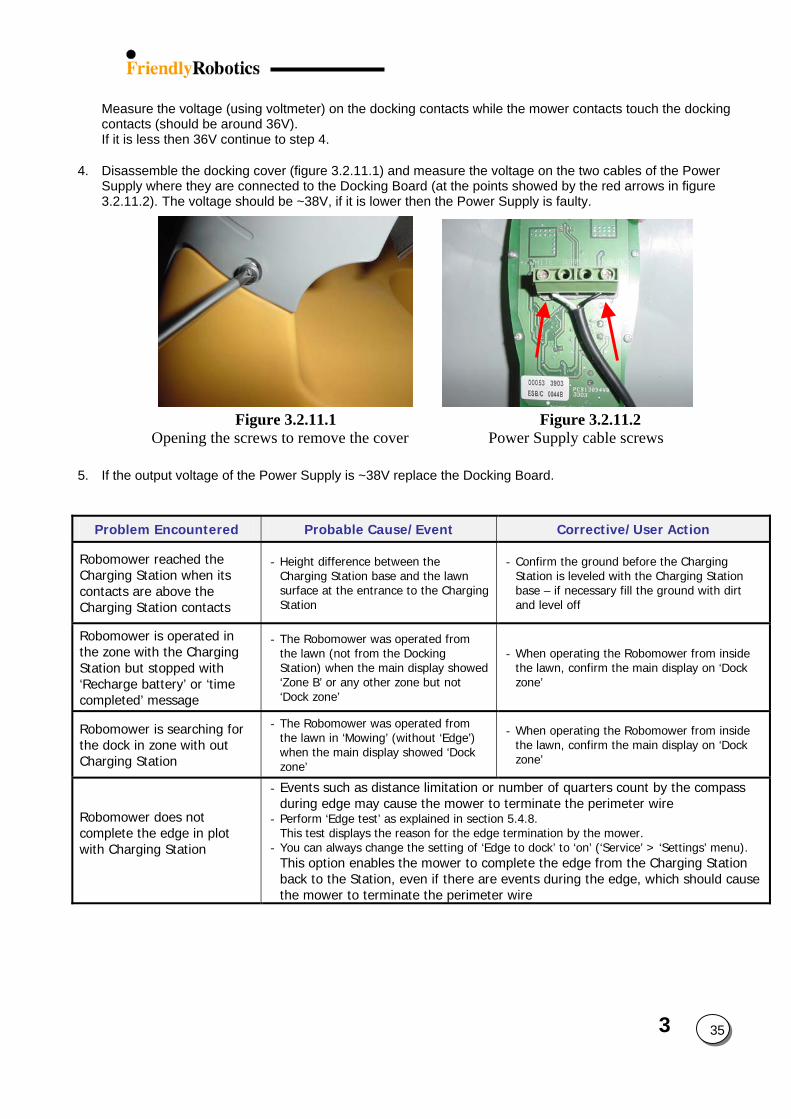
3
Measure the voltage (using voltmeter) on the docking contacts while the mower contacts touch the docking contacts (should be around 36V). If it is less then 36V continue to step 4.
4. Disassemble the docking cover (figure 3.2.11.1) and measure the voltage on the two cables of the Power Supply where they are connected to the Docking Board (at the points showed by the red arrows in figure 3.2.11.2). The voltage should be ~38V, if it is lower then the Power Supply is faulty.
Figure 3.2.11.1 Figure 3.2.11.2 Opening the screws to remove the cover Power Supply cable screws
5. If the output voltage of the Power Supply is ~38V replace the Docking Board.
Problem Encountered Probable Cause/Event Corrective/User Action
Robomower reached the Charging Station when its contacts are above the Charging Station contacts
- Height difference between the Charging Station base and the lawn surface at the entrance to the Charging Station
- Confirm the ground before the Charging Station is leveled with the Charging Station base – if necessary fill the ground with dirt and level off
Robomower is operated in the zone with the Charging Station but stopped with ‘Recharge battery’ or ‘time completed’ message
- The Robomower was operated from the lawn (not from the Docking Station) when the main display showed ‘Zone B’ or any other zone but not ‘Dock zone’
- When operating the Robomower from inside the lawn, confirm the main display on ‘Dock zone’
Robomower is searching for the dock in zone with out Charging Station
- The Robomower was operated from the lawn in ‘Mowing’ (without ‘Edge’) when the main display showed ‘Dock zone’
- When operating the Robomower from inside the lawn, confirm the main display on ‘Dock zone’
Robomower does not complete the edge in plot with Charging Station
- Events such as distance limitation or number of quarters count by the compass during edge may cause the mower to terminate the perimeter wire
- Perform ‘Edge test’ as explained in section 5.4.8. This test displays the reason for the edge termination by the mower.
- You can always change the setting of ‘Edge to dock’ to ‘on’ (‘Service’ > ‘Settings’ menu). This option enables the mower to complete the edge from the Charging Station back to the Station, even if there are events during the edge, which should cause the mower to terminate the perimeter wire
35
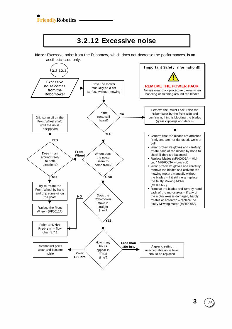
3.2.12 Excessive noise
Is the noise still heard?
Where does the noise seem to
come from?
Does it turn around freely
to both directions?
How many hours
appear in ‘Total time’?
3.2.12.1
Note: Excessive noise from the Robomow, which does not decrease the performances, is an aesthetic issue only.
Drive the mower manually on a flat
surface without mowing
Excessive noise comes
from the Robomower
NO
YES
Mechanical parts wear and become
noisier Over 150 hrs.
Refer to ‘Drive Problem’ – flow
chart 3.7.1
NO
Try to rotate the Front Wheel by hand and drip some oil on
the shaft
Replace the Front Wheel (SPP0011A)
NO
YES
Does the Robomower
move in straight lines?
Important Safety Information!!!
REMOVE THE POWER PACK.Always wear thick protective gloves when handling or cleaning around the blades
Confirm that the blades are attached firmly and are not damaged, worn or dull. Wear protective gloves and carefully rotate each of the blades by hand to check if they are balanced. Replace blades (MRK0002A – High cut / MRK0003A – Low cut) Wear protective gloves and carefully remove the blades and activate the mowing motors manually without the blades – if it still noisy replace the faulty Mowing Motor (MSB0065B) Remove the blades and turn by hand each of the motor axes – if any of the motor axes is damaged, hardly rotates or eccentric – replace the faulty Mowing Motor (MSB0065B)
Remove the Power Pack, raise the Robomower by the front side and
confirm nothing is blocking the blades (grass clippings and debris)
Drip some oil on the Front Wheel shaft
until the noise disappears
YES
Front Wheel
Gear
3 36A gear creating unacceptable noise level
should be replaced
Less than 150 hrs.
4. Repair and Maintenance Procedures
The Repair and Maintenance Procedures Section is broadly divided into two areas, External
and Internal. The External procedures include all those procedures that can be completed without the removal of the cover and conversely all Internal procedures require the removal of the cover of the unit.
Always follow procedures step by step and ensure good workshop practice by working in
clean, dry conditions. Use only correct, well-maintained tools. At the top of each procedure, the tools required are listed, as well as the time needed to complete the procedure. The time stated tends to be generous, allowing time for diagnostics, reviewing the relevant procedures in the Service Guide and completing the General Test (See section 5.1) before the unit is sent back to the customer.
Always complete testing to ensure safety and proper operation of the unit. When completing
work, always record the FCS (Friendly Coding System) code on any report or claims to Friendly Robotics (See section 6 – Procedures and Policies)
4 1
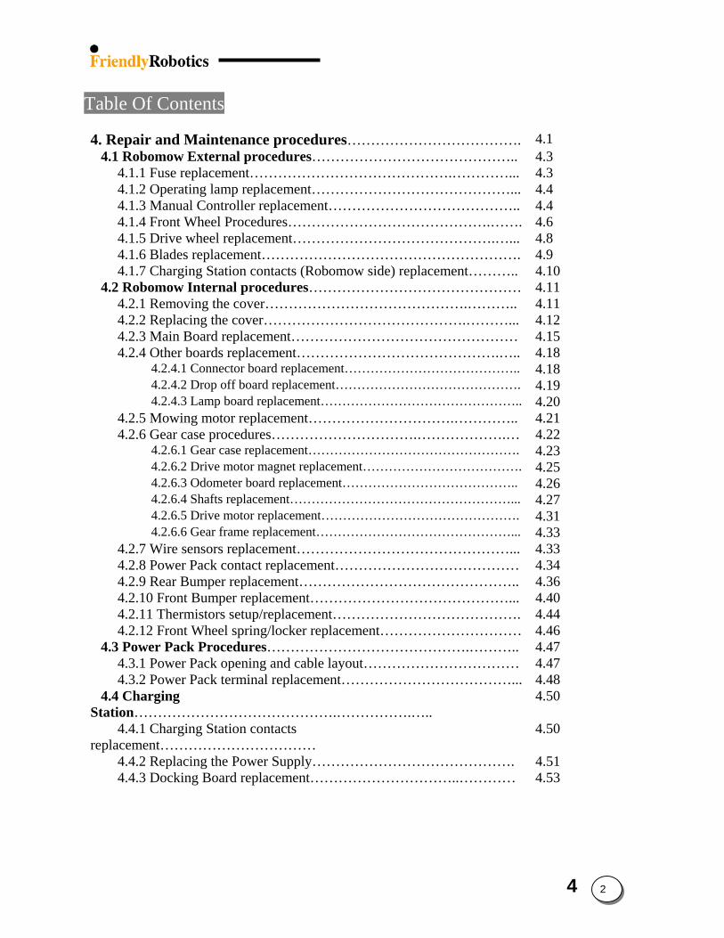
Table Of Contents
4. Repair and Maintenance procedures………………………………. 4.1 4.1 Robomow External procedures…………………………………….. 4.3
4.1.1 Fuse replacement…………………………………….…………... 4.3 4.1.2 Operating lamp replacement……………………………………... 4.4 4.1.3 Manual Controller replacement………………………………….. 4.4 4.1.4 Front Wheel Procedures…………………………………….……. 4.6 4.1.5 Drive wheel replacement…………………………………….…... 4.8 4.1.6 Blades replacement………………………………………………. 4.9 4.1.7 Charging Station contacts (Robomow side) replacement……….. 4.10
4.2 Robomow Internal procedures……………………………………… 4.11 4.2.1 Removing the cover…………………………………….……….. 4.11 4.2.2 Replacing the cover…………………………………….………... 4.12 4.2.3 Main Board replacement………………………………………… 4.15 4.2.4 Other boards replacement…………………………………….….. 4.18
4.2.4.1 Connector board replacement………………………………….. 4.18 4.2.4.2 Drop off board replacement……………………………………. 4.19 4.2.4.3 Lamp board replacement……………………………………….. 4.20
4.2.5 Mowing motor replacement………………………….………….. 4.21 4.2.6 Gear case procedures………………………….……………….… 4.22
4.2.6.1 Gear case replacement…………………………………………. 4.23 4.2.6.2 Drive motor magnet replacement………………………………. 4.25 4.2.6.3 Odometer board replacement………………………………….. 4.26 4.2.6.4 Shafts replacement……………………………………………... 4.27 4.2.6.5 Drive motor replacement………………………………………. 4.31 4.2.6.6 Gear frame replacement………………………………………... 4.33
4.2.7 Wire sensors replacement………………………………………... 4.33 4.2.8 Power Pack contact replacement………………………………… 4.34 4.2.9 Rear Bumper replacement……………………………………….. 4.36 4.2.10 Front Bumper replacement……………………………………... 4.40 4.2.11 Thermistors setup/replacement…………………………………. 4.44 4.2.12 Front Wheel spring/locker replacement………………………… 4.46
4.3 Power Pack Procedures…………………………………….……….. 4.47 4.3.1 Power Pack opening and cable layout…………………………… 4.47 4.3.2 Power Pack terminal replacement………………………………... 4.48
4.4 Charging Station…………………………………….…………….…..
4.50
4.4.1 Charging Station contacts replacement……………………………
4.50
4.4.2 Replacing the Power Supply……………………………………. 4.51 4.4.3 Docking Board replacement…………………………..………… 4.53
4 2
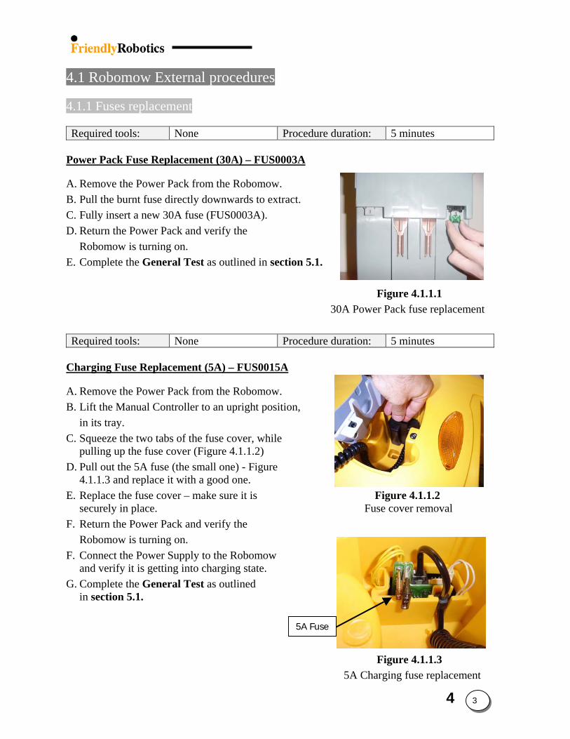
4.1 Robomow External procedures 4.1.1 Fuses replacement
Required tools: None Procedure duration: 5 minutes
Power Pack Fuse Replacement (30A) – FUS0003A
5A Fuse
A. Remove the Power Pack from the Robomow. B. Pull the burnt fuse directly downwards to extract. C. Fully insert a new 30A fuse (FUS0003A). D. Return the Power Pack and verify the
Robomow is turning on. E. Complete the General Test as outlined in section 5.1.
Figure 4.1.1.1 30A Power Pack fuse replacement
Required tools: None Procedure duration: 5 minutes
Charging Fuse Replacement (5A) – FUS0015A
A. Remove the Power Pack from the Robomow. B. Lift the Manual Controller to an upright position,
in its tray. C. Squeeze the two tabs of the fuse cover, while
pulling up the fuse cover (Figure 4.1.1.2) D. Pull out the 5A fuse (the small one) - Figure
4.1.1.3 and replace it with a good one. E. Replace the fuse cover – make sure it is Figure 4.1.1.2
securely in place. Fuse cover removal F. Return the Power Pack and verify the
Robomow is turning on. F. Connect the Power Supply to the Robomow
and verify it is getting into charging state. G. Complete the General Test as outlined
in section 5.1.
Figure 4.1.1.3 5A Charging fuse replacement
4 3
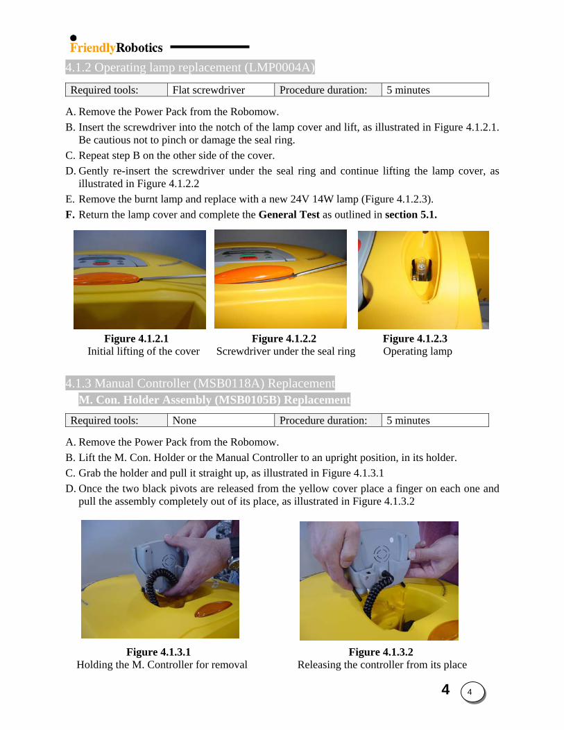
4.1.2 Operating lamp replacement (LMP0004A)
Required tools: Flat screwdriver Procedure duration: 5 minutes A. Remove the Power Pack from the Robomow. B. Insert the screwdriver into the notch of the lamp cover and lift, as illustrated in Figure 4.1.2.1.
Be cautious not to pinch or damage the seal ring. C. Repeat step B on the other side of the cover. D. Gently re-insert the screwdriver under the seal ring and continue lifting the lamp cover, as
illustrated in Figure 4.1.2.2 E. Remove the burnt lamp and replace with a new 24V 14W lamp (Figure 4.1.2.3). F. Return the lamp cover and complete the General Test as outlined in section 5.1. Figure 4.1.2.1 Figure 4.1.2.2 Figure 4.1.2.3 Initial lifting of the cover Screwdriver under the seal ring Operating lamp 4.1.3 Manual Controller (MSB0118A) Replacement
M. Con. Holder Assembly (MSB0105B) Replacement
Required tools: None Procedure duration: 5 minutes A. Remove the Power Pack from the Robomow. B. Lift the M. Con. Holder or the Manual Controller to an upright position, in its holder. C. Grab the holder and pull it straight up, as illustrated in Figure 4.1.3.1 D. Once the two black pivots are released from the yellow cover place a finger on each one and
pull the assembly completely out of its place, as illustrated in Figure 4.1.3.2
Figure 4.1.3.1 Figure 4.1.3.2 Holding the M. Controller for removal Releasing the controller from its place
4 4
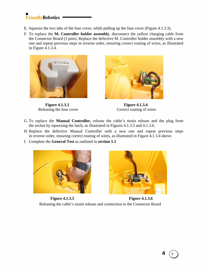
E. Squeeze the two tabs of the fuse cover, while pulling up the fuse cover (Figure 4.1.3.3). F. To replace the M. Controller holder assembly, disconnect the yellow charging cable from
the Connector Board (3 pins). Replace the defective M. Controller holder assembly with a new one and repeat previous steps in reverse order, ensuring correct routing of wires, as illustrated in Figure 4.1.3.4.
Figure 4.1.3.3 Figure 4.1.3.4 Releasing the fuse cover Correct routing of wires
G. To replace the Manual Controller, release the cable’s strain release and the plug from
the socket by squeezing the latch, as illustrated in Figures 4.1.3.5 and 4.1.3.6. H. Replace the defective Manual Controller with a new one and repeat previous steps
in reverse order, ensuring correct routing of wires, as illustrated in Figure 4.1.3.4 above. I. Complete the General Test as outlined in section 5.1
Figure 4.1.3.5 Figure 4.1.3.6 Releasing the cable’s strain release and connection to the Connector Board
4 5
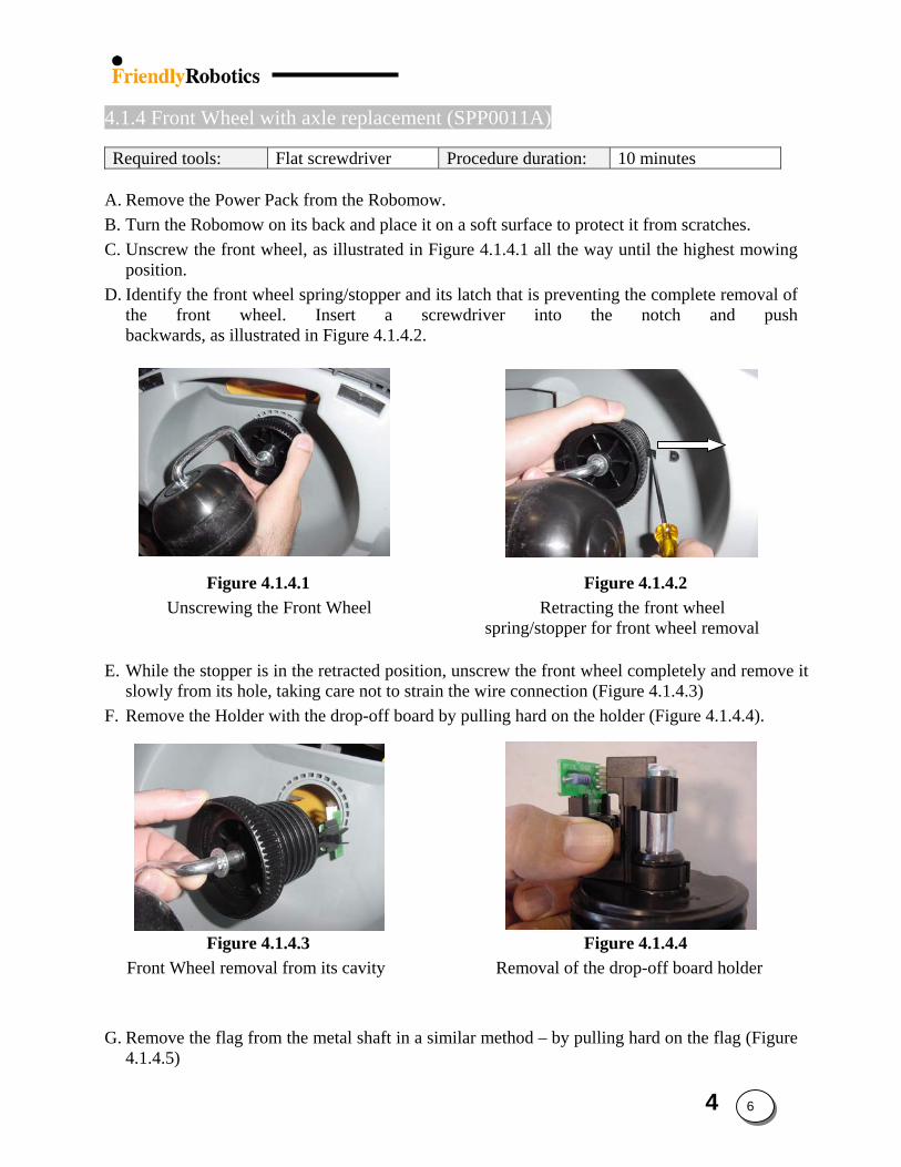
4.1.4 Front Wheel with axle replacement (SPP0011A)
Required tools: Flat screwdriver Procedure duration: 10 minutes A. Remove the Power Pack from the Robomow. B. Turn the Robomow on its back and place it on a soft surface to protect it from scratches. C. Unscrew the front wheel, as illustrated in Figure 4.1.4.1 all the way until the highest mowing
position. D. Identify the front wheel spring/stopper and its latch that is preventing the complete removal of
the front wheel. Insert a screwdriver into the notch and push backwards, as illustrated in Figure 4.1.4.2.
Figure 4.1.4.1 Figure 4.1.4.2 Unscrewing the Front Wheel Retracting the front wheel
spring/stopper for front wheel removal
E. While the stopper is in the retracted position, unscrew the front wheel completely and remove it slowly from its hole, taking care not to strain the wire connection (Figure 4.1.4.3)
F. Remove the Holder with the drop-off board by pulling hard on the holder (Figure 4.1.4.4).
Figure 4.1.4.3 Figure 4.1.4.4
Front Wheel removal from its cavity Removal of the drop-off board holder G. Remove the flag from the metal shaft in a similar method – by pulling hard on the flag (Figure
4.1.4.5)
4 6
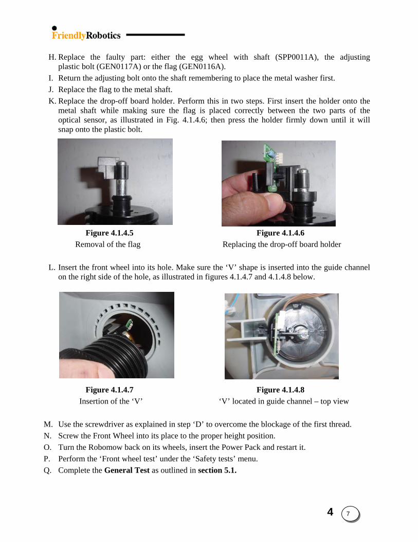
H. Replace the faulty part: either the egg wheel with shaft (SPP0011A), the adjusting
plastic bolt (GEN0117A) or the flag (GEN0116A). I. Return the adjusting bolt onto the shaft remembering to place the metal washer first. J. Replace the flag to the metal shaft. K. Replace the drop-off board holder. Perform this in two steps. First insert the holder onto the
metal shaft while making sure the flag is placed correctly between the two parts of the optical sensor, as illustrated in Fig. 4.1.4.6; then press the holder firmly down until it will snap onto the plastic bolt.
Figure 4.1.4.5 Figure 4.1.4.6
Removal of the flag Replacing the drop-off board holder
L. Insert the front wheel into its hole. Make sure the ‘V’ shape is inserted into the guide channel on the right side of the hole, as illustrated in figures 4.1.4.7 and 4.1.4.8 below.
Figure 4.1.4.7 Figure 4.1.4.8 Insertion of the ‘V’ ‘V’ located in guide channel – top view
M. Use the screwdriver as explained in step ‘D’ to overcome the blockage of the first thread. N. Screw the Front Wheel into its place to the proper height position. O. Turn the Robomow back on its wheels, insert the Power Pack and restart it. P. Perform the ‘Front wheel test’ under the ‘Safety tests’ menu. Q. Complete the General Test as outlined in section 5.1.
4 7
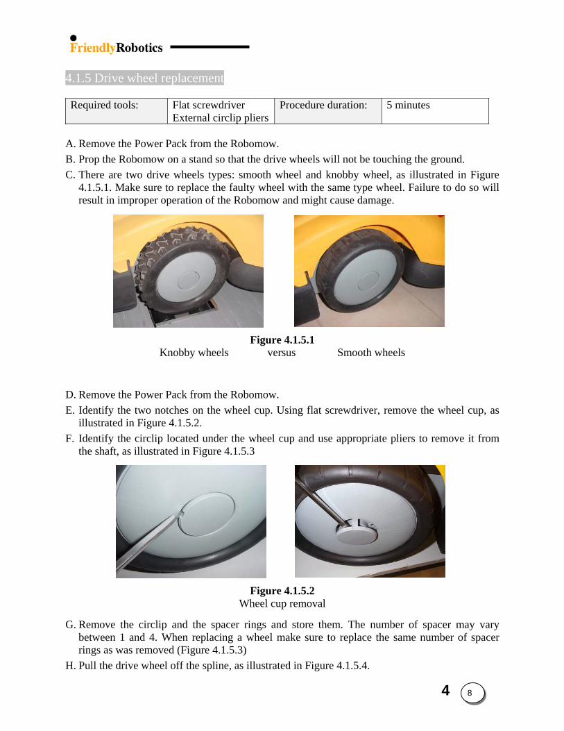
4.1.5 Drive wheel replacement Required tools: Flat screwdriver
External circlip pliers Procedure duration: 5 minutes
A. Remove the Power Pack from the Robomow. B. Prop the Robomow on a stand so that the drive wheels will not be touching the ground. C. There are two drive wheels types: smooth wheel and knobby wheel, as illustrated in Figure
4.1.5.1. Make sure to replace the faulty wheel with the same type wheel. Failure to do so will result in improper operation of the Robomow and might cause damage.
Figure 4.1.5.1 Knobby wheels versus Smooth wheels
D. Remove the Power Pack from the Robomow. E. Identify the two notches on the wheel cup. Using flat screwdriver, remove the wheel cup, as
illustrated in Figure 4.1.5.2. F. Identify the circlip located under the wheel cup and use appropriate pliers to remove it from
the shaft, as illustrated in Figure 4.1.5.3
Figure 4.1.5.2 Wheel cup removal
G. Remove the circlip and the spacer rings and store them. The number of spacer may vary between 1 and 4. When replacing a wheel make sure to replace the same number of spacer rings as was removed (Figure 4.1.5.3)
H. Pull the drive wheel off the spline, as illustrated in Figure 4.1.5.4.
4 8
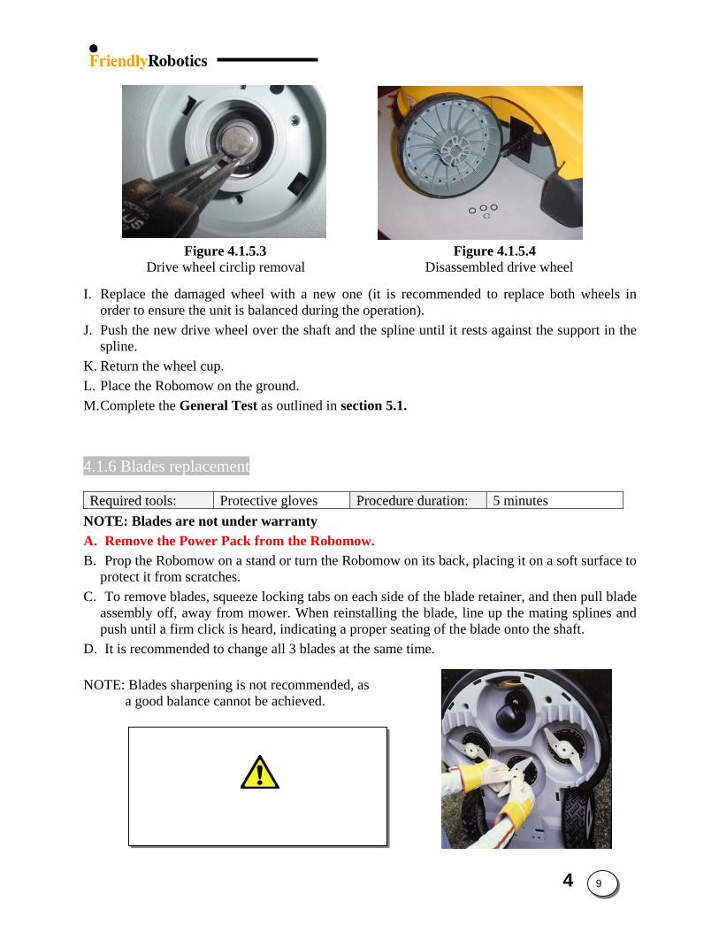
Figure 4.1.5.3 Figure 4.1.5.4
Drive wheel circlip removal Disassembled drive wheel
I. Replace the damaged wheel with a new one (it is recommended to replace both wheels in order to ensure the unit is balanced during the operation).
J. Push the new drive wheel over the shaft and the spline until it rests against the support in the spline.
K. Return the wheel cup. L. Place the Robomow on the ground. M. Complete the General Test as outlined in section 5.1. 4.1.6 Blades replacement Required tools: Protective gloves Procedure duration: 5 minutes
NOTE: Blades are not under warranty A. Remove the Power Pack from the Robomow. B. Prop the Robomow on a stand or turn the Robomow on its back, placing it on a soft surface to
protect it from scratches. C. To remove blades, squeeze locking tabs on each side of the blade retainer, and then pull blade
assembly off, away from mower. When reinstalling the blade, line up the mating splines and push until a firm click is heard, indicating a proper seating of the blade onto the shaft.
D. It is recommended to change all 3 blades at the same time.
Important Safety Information!!!
REMOVE THE POWER PACK. Always wear thick protective gloves when
handling or cleaning around the blades
NOTE: Blades sharpening is not recommended, as a good balance cannot be achieved.
4 9
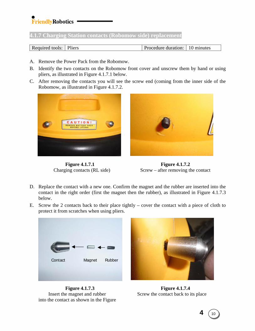
4.1.7 Charging Station contacts (Robomow side) replacement
Required tools: Pliers Procedure duration: 10 minutes
A. Remove the Power Pack from the Robomow. B. Identify the two contacts on the Robomow front cover and unscrew them by hand or using
pliers, as illustrated in Figure 4.1.7.1 below. C. After removing the contacts you will see the screw end (coming from the inner side of the
Robomow, as illustrated in Figure 4.1.7.2.
Figure 4.1.7.1 Figure 4.1.7.2 Charging contacts (RL side) Screw – after removing the contact
D. Replace the contact with a new one. Confirm the magnet and the rubber are inserted into the
contact in the right order (first the magnet then the rubber), as illustrated in Figure 4.1.7.3 below.
E. Screw the 2 contacts back to their place tightly – cover the contact with a piece of cloth to protect it from scratches when using pliers.
r
Iinto t
Contact Magnet Rubbe
Figure 4.1.7.3 Figure 4.1.7.4 nsert the magnet and rubber Screw the contact back to its place he contact as shown in the Figure
4 10
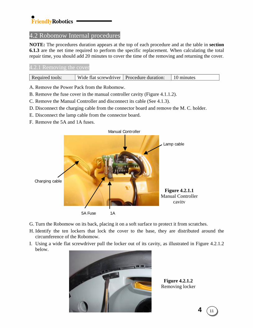
4.2 Robomow Internal procedures NOTE: The procedures duration appears at the top of each procedure and at the table in section 6.1.3 are the net time required to perform the specific replacement. When calculating the total repair time, you should add 20 minutes to cover the time of the removing and returning the cover.
4.2.1 Removing the cover
Required tools: Wide flat screwdriver Procedure duration: 10 minutes A. Remove the Power Pack from the Robomow. B. Remove the fuse cover in the manual controller cavity (Figure 4.1.1.2). C. Remove the Manual Controller and disconnect its cable (See 4.1.3). D. Disconnect the charging cable from the connector board and remove the M. C. holder. E. Disconnect the lamp cable from the connector board.
Manual Controller
Figure 4.2.1.1 Manual Controller
cavity
Charging cable
Lamp cable
5A Fuse 1A
F. Remove the 5A and 1A fuses.
G. Turn the Robomow on its back, placing it on a soft surface to protect it from scratches. H. Identify the ten lockers that lock the cover to the base, they are distributed around the
circumference of the Robomow. I. Using a wide flat screwdriver pull the locker out of its cavity, as illustrated in Figure 4.2.1.2
below.
Figure 4.2.1.2 Removing locker
4 11
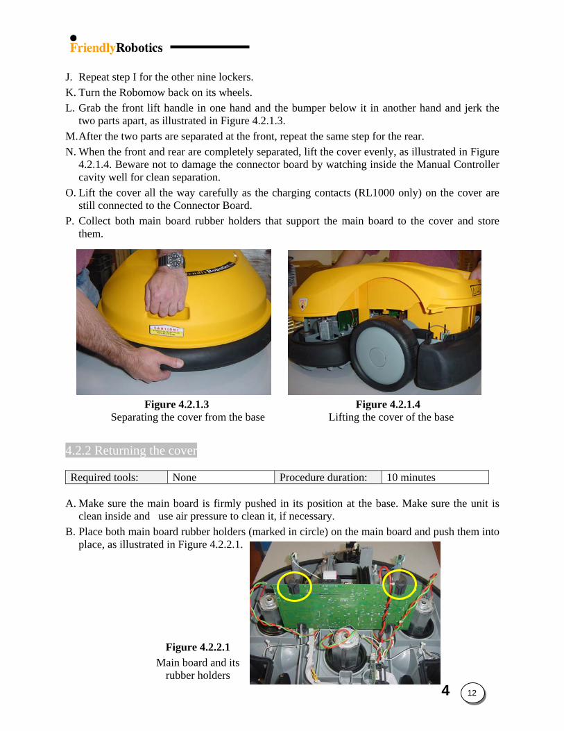
J. Repeat step I for the other nine lockers. K. Turn the Robomow back on its wheels. L. Grab the front lift handle in one hand and the bumper below it in another hand and jerk the
two parts apart, as illustrated in Figure 4.2.1.3. M. After the two parts are separated at the front, repeat the same step for the rear. N. When the front and rear are completely separated, lift the cover evenly, as illustrated in Figure
4.2.1.4. Beware not to damage the connector board by watching inside the Manual Controller cavity well for clean separation.
O. Lift the cover all the way carefully as the charging contacts (RL1000 only) on the cover are still connected to the Connector Board.
P. Collect both main board rubber holders that support the main board to the cover and store them.
Figure 4.2.1.3 Figure 4.2.1.4 Separating the cover from the base Lifting the cover of the base
4.2.2 Returning the cover Required tools: None Procedure duration: 10 minutes
A. Make sure the main board is firmly pushed in its position at the base. Make sure the unit is
clean inside and use air pressure to clean it, if necessary.
Figure 4.2.2.1 Main board and its
rubber holders
B. Place both main board rubber holders (marked in circle) on the main board and push them into place, as illustrated in Figure 4.2.2.1.
4 12
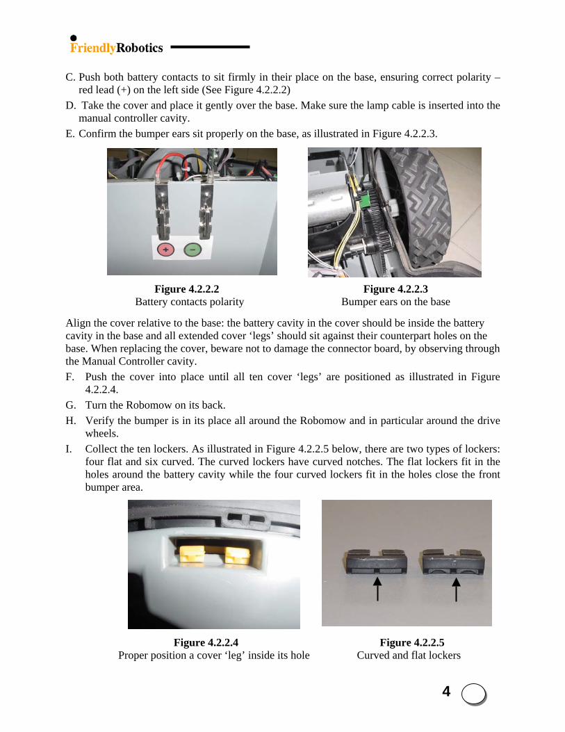
4
C. Push both battery contacts to sit firmly in their place on the base, ensuring correct polarity –
red lead (+) on the left side (See Figure 4.2.2.2) D. Take the cover and place it gently over the base. Make sure the lamp cable is inserted into the
manual controller cavity. E. Confirm the bumper ears sit properly on the base, as illustrated in Figure 4.2.2.3.
Figure 4.2.2.2 Figure 4.2.2.3 Battery contacts polarity Bumper ears on the base
Align the cover relative to the base: the battery cavity in the cover should be inside the battery cavity in the base and all extended cover ‘legs’ should sit against their counterpart holes on the base. When replacing the cover, beware not to damage the connector board, by observing through the Manual Controller cavity. F. Push the cover into place until all ten cover ‘legs’ are positioned as illustrated in Figure
4.2.2.4. G. Turn the Robomow on its back. H. Verify the bumper is in its place all around the Robomow and in particular around the drive
wheels.
13
Flat Curved
I. Collect the ten lockers. As illustrated in Figure 4.2.2.5 below, there are two types of lockers: four flat and six curved. The curved lockers have curved notches. The flat lockers fit in the holes around the battery cavity while the four curved lockers fit in the holes close the front bumper area.
Figure 4.2.2.4 Figure 4.2.2.5 Proper position a cover ‘leg’ inside its hole Curved and flat lockers
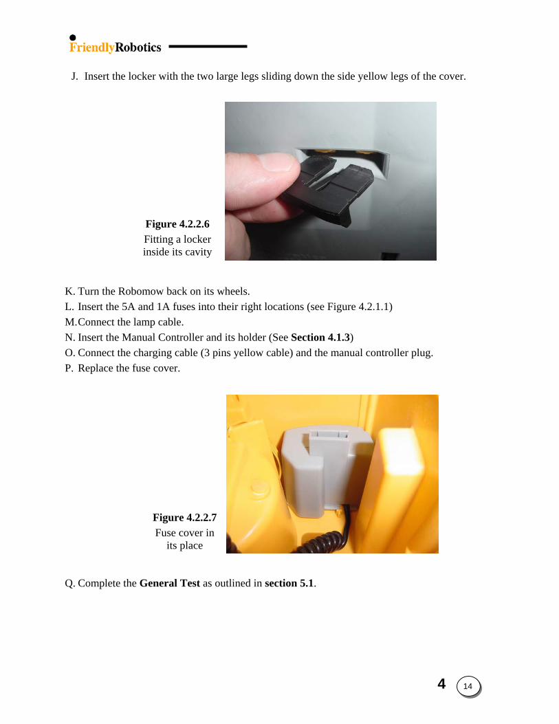
Figure 4.2.2.6 Fitting a locker inside its cavity
J. Insert the locker with the two large legs sliding down the side yellow legs of the cover.
K. Turn the Robomow back on its wheels. L. Insert the 5A and 1A fuses into their right locations (see Figure 4.2.1.1) M. Connect the lamp cable. N. Insert the Manual Controller and its holder (See Section 4.1.3) O. Connect the charging cable (3 pins yellow cable) and the manual controller plug.
Figure 4.2.2.7 Fuse cover in
its place
P. Replace the fuse cover.
Q. Complete the General Test as outlined in section 5.1.
4 14
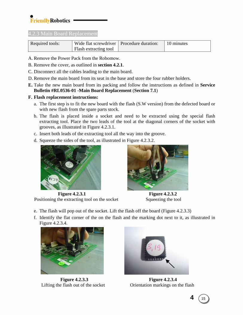
4.2.3 Main Board Replacement
Required tools: Wide flat screwdriver Flash extracting tool
Procedure duration: 10 minutes
A. Remove the Power Pack from the Robomow. B. Remove the cover, as outlined in section 4.2.1. C. Disconnect all the cables leading to the main board. D. Remove the main board from its seat in the base and store the four rubber holders. E. Take the new main board from its packing and follow the instructions as defined in Service
Bulletin #RL0536-01 -Main Board Replacement (Section 7.1) F. Flash replacement instructions:
a. The first step is to fit the new board with the flash (S.W version) from the defected board or with new flash from the spare parts stock.
b. The flash is placed inside a socket and need to be extracted using the special flash extracting tool. Place the two leads of the tool at the diagonal corners of the socket with grooves, as illustrated in Figure 4.2.3.1.
c. Insert both leads of the extracting tool all the way into the groove. d. Squeeze the sides of the tool, as illustrated in Figure 4.2.3.2.
Figure 4.2.3.1 Figure 4.2.3.2 Positioning the extracting tool on the socket Squeezing the tool
e. The flash will pop out of the socket. Lift the flash off the board (Figure 4.2.3.3)
Flat corner
f. Identify the flat corner of the on the flash and the marking dot next to it, as illustrated in Figure 4.2.3.4.
Figure 4.2.3.3 Figure 4.2.3.4 Lifting the flash out of the socket Orientation markings on the flash
4 15
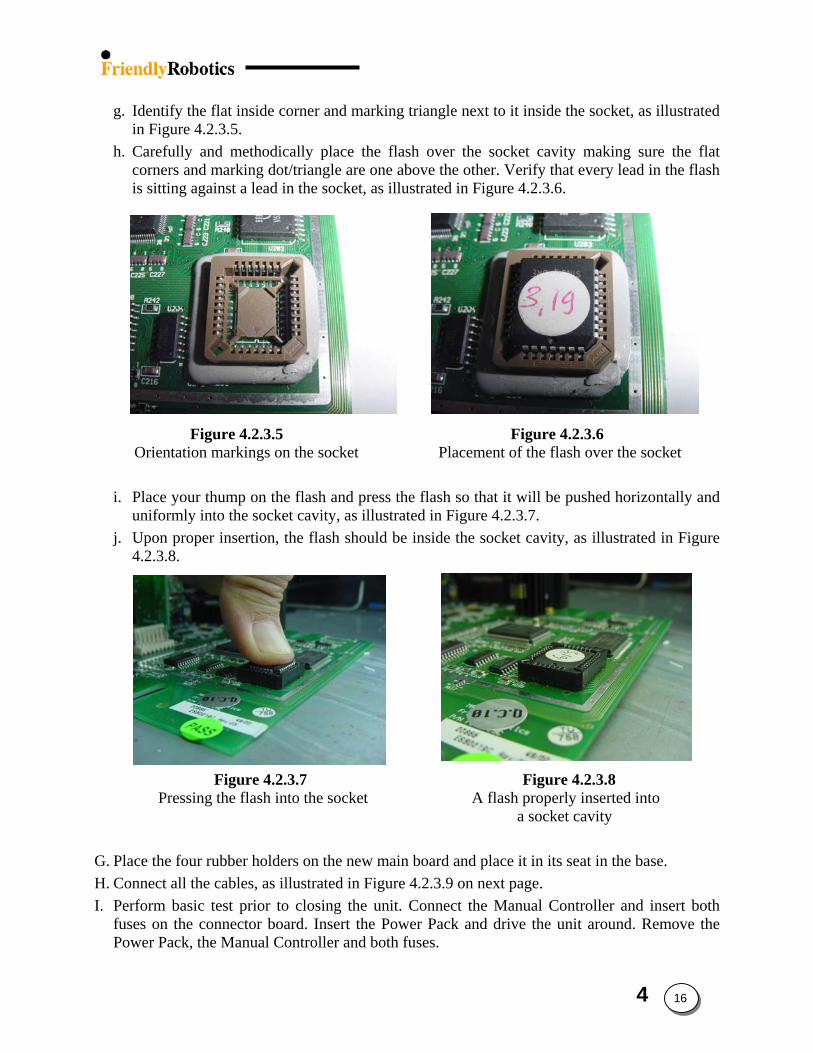
g. Identify the flat inside corner and marking triangle next to it inside the socket, as illustrated
in Figure 4.2.3.5. h. Carefully and methodically place the flash over the socket cavity making sure the flat
corners and marking dot/triangle are one above the other. Verify that every lead in the flash is sitting against a lead in the socket, as illustrated in Figure 4.2.3.6.
Figure 4.2.3.5 Figure 4.2.3.6 Orientation markings on the socket Placement of the flash over the socket
i. Place your thump on the flash and press the flash so that it will be pushed horizontally and uniformly into the socket cavity, as illustrated in Figure 4.2.3.7.
j. Upon proper insertion, the flash should be inside the socket cavity, as illustrated in Figure 4.2.3.8.
Figure 4.2.3.7 Figure 4.2.3.8 Pressing the flash into the socket A flash properly inserted into
a socket cavity
G. Place the four rubber holders on the new main board and place it in its seat in the base. H. Connect all the cables, as illustrated in Figure 4.2.3.9 on next page. I. Perform basic test prior to closing the unit. Connect the Manual Controller and insert both
fuses on the connector board. Insert the Power Pack and drive the unit around. Remove the Power Pack, the Manual Controller and both fuses.
4 16
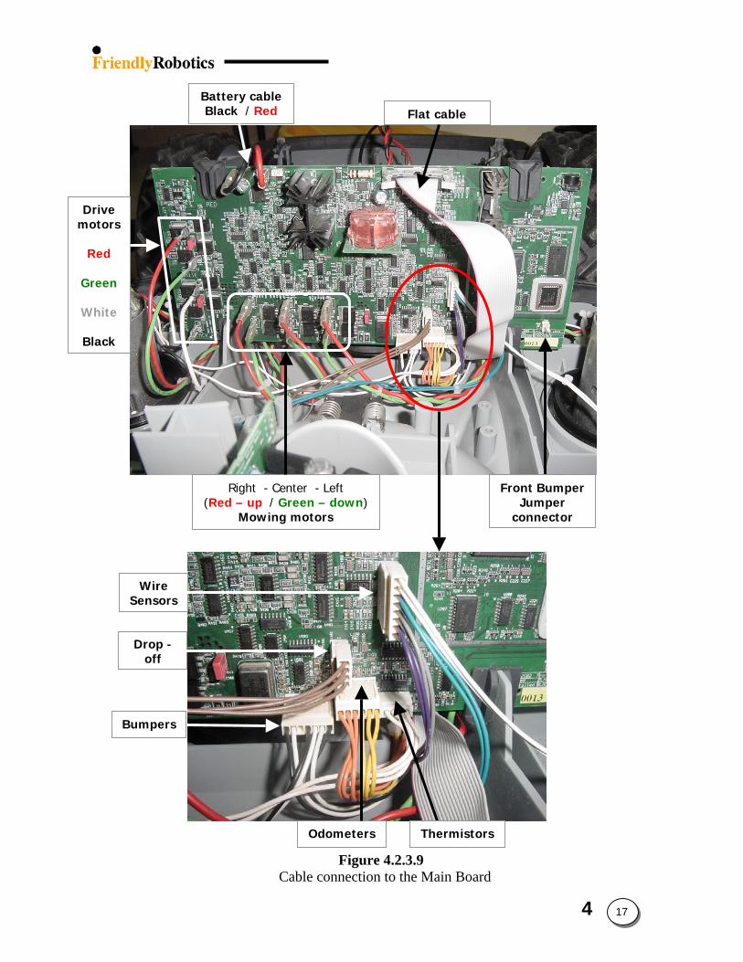
Right - Center - Left (Red – up / Green – down)
Mowing motors
Drive motors
Red
Green
White
Black
Battery cable Black / Red Flat cable
Front Bumper Jumper
connector
Wire Sensors
Drop - off
Odometers Thermistors
Bumpers
Figure 4.2.3.9 Cable connection to the Main Board
4 17
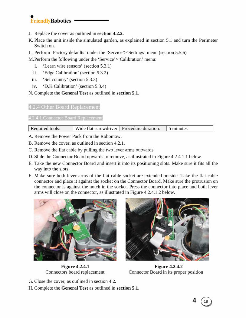
J. Replace the cover as outlined in section 4.2.2. K. Place the unit inside the simulated garden, as explained in section 5.1 and turn the Perimeter
Switch on. L. Perform ‘Factory defaults’ under the ‘Service’>’Settings’ menu (section 5.5.6) M. Perform the following under the ‘Service’>’Calibration’ menu:
i. ‘Learn wire sensors’ (section 5.3.1) ii. ‘Edge Calibration’ (section 5.3.2)
iii. ‘Set country’ (section 5.3.3) iv. ‘D.K Calibration’ (section 5.3.4)
N. Complete the General Test as outlined in section 5.1.
4.2.4 Other Board Replacement
4.2.4.1 Connector Board Replacement
Required tools: Wide flat screwdriver Procedure duration: 5 minutes
A. Remove the Power Pack from the Robomow. B. Remove the cover, as outlined in section 4.2.1. C. Remove the flat cable by pulling the two lever arms outwards. D. Slide the Connector Board upwards to remove, as illustrated in Figure 4.2.4.1.1 below. E. Take the new Connector Board and insert it into its positioning slots. Make sure it fits all the
way into the slots. F. Make sure both lever arms of the flat cable socket are extended outside. Take the flat cable
connector and place it against the socket on the Connector Board. Make sure the protrusion on the connector is against the notch in the socket. Press the connector into place and both lever arms will close on the connector, as illustrated in Figure 4.2.4.1.2 below.
Figure 4.2.4.1 Figure 4.2.4.2 Connectors board replacement Connector Board in its proper position G. Close the cover, as outlined in section 4.2. H. Complete the General Test as outlined in section 5.1.
4 18
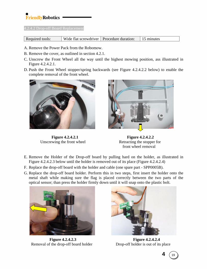
4.2.4.2 Drop-off Board Replacement
Required tools: Wide flat screwdriver Procedure duration: 15 minutes
A. Remove the Power Pack from the Robomow. B. Remove the cover, as outlined in section 4.2.1. C. Unscrew the Front Wheel all the way until the highest mowing position, ass illustrated in
Figure 4.2.4.2.1. D. Push the Front Wheel stopper/spring backwards (see Figure 4.2.4.2.2 below) to enable the
complete removal of the front wheel. Figure 4.2.4.2.1 Figure 4.2.4.2.2
Unscrewing the front wheel Retracting the stopper for front wheel removal E. Remove the Holder of the Drop-off board by pulling hard on the holder, as illustrated in
Figure 4.2.4.2.3 below until the holder is removed out of its place (Figure 4.2.4.2.4) F. Replace the drop-off board with the holder and cable (one spare part - SPP0005B). G. Replace the drop-off board holder. Perform this in two steps, first insert the holder onto the
metal shaft while making sure the flag is placed correctly between the two parts of the optical sensor; than press the holder firmly down until it will snap onto the plastic bolt.
Figure 4.2.4.2.3 Figure 4.2.4.2.4
Removal of the drop-off board holder Drop-off holder is out of its place
4 19
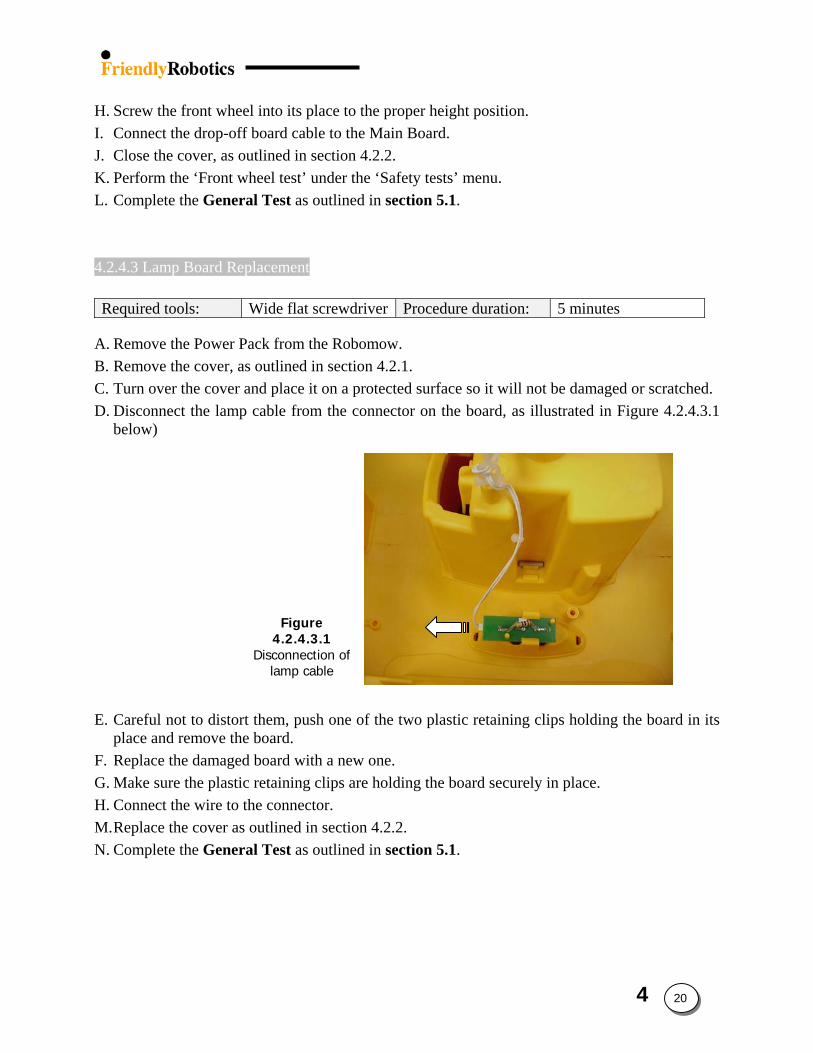
H. Screw the front wheel into its place to the proper height position. I. Connect the drop-off board cable to the Main Board. J. Close the cover, as outlined in section 4.2.2. K. Perform the ‘Front wheel test’ under the ‘Safety tests’ menu. L. Complete the General Test as outlined in section 5.1.
4.2.4.3 Lamp Board Replacement
Required tools: Wide flat screwdriver Procedure duration: 5 minutes
A. Remove the Power Pack from the Robomow. B. Remove the cover, as outlined in section 4.2.1. C. Turn over the cover and place it on a protected surface so it will not be damaged or scratched.
Figure 4.2.4.3.1
Disconnection of lamp cable
D. Disconnect the lamp cable from the connector on the board, as illustrated in Figure 4.2.4.3.1 below)
E. Careful not to distort them, push one of the two plastic retaining clips holding the board in its place and remove the board.
F. Replace the damaged board with a new one. G. Make sure the plastic retaining clips are holding the board securely in place. H. Connect the wire to the connector. M. Replace the cover as outlined in section 4.2.2. N. Complete the General Test as outlined in section 5.1.
4 20
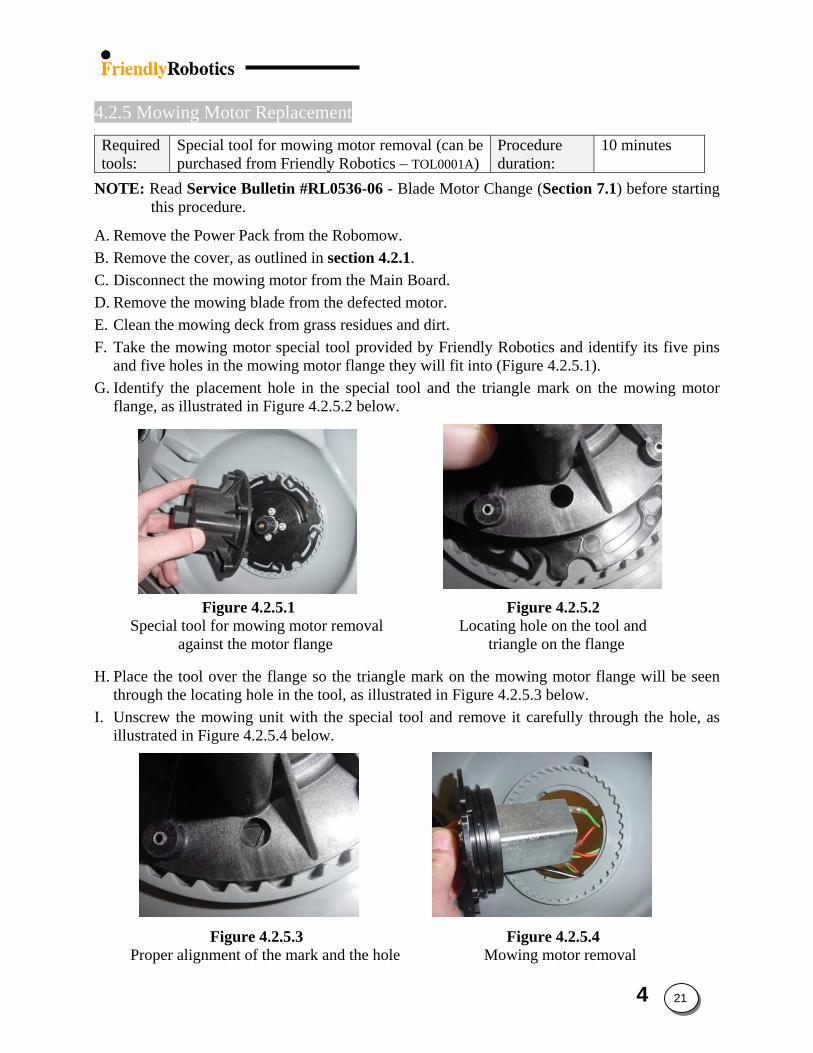
4.2.5 Mowing Motor Replacement
Required tools:
Special tool for mowing motor removal (can be purchased from Friendly Robotics – TOL0001A)
Procedure duration:
10 minutes
NOTE: Read Service Bulletin #RL0536-06 - Blade Motor Change (Section 7.1) before starting this procedure.
A. Remove the Power Pack from the Robomow. B. Remove the cover, as outlined in section 4.2.1. C. Disconnect the mowing motor from the Main Board. D. Remove the mowing blade from the defected motor. E. Clean the mowing deck from grass residues and dirt. F. Take the mowing motor special tool provided by Friendly Robotics and identify its five pins
and five holes in the mowing motor flange they will fit into (Figure 4.2.5.1). G. Identify the placement hole in the special tool and the triangle mark on the mowing motor
flange, as illustrated in Figure 4.2.5.2 below.
Figure 4.2.5.1 Figure 4.2.5.2 Special tool for mowing motor removal Locating hole on the tool and against the motor flange triangle on the flange
H. Place the tool over the flange so the triangle mark on the mowing motor flange will be seen through the locating hole in the tool, as illustrated in Figure 4.2.5.3 below.
I. Unscrew the mowing unit with the special tool and remove it carefully through the hole, as illustrated in Figure 4.2.5.4 below.
Figure 4.2.5.3 Figure 4.2.5.4 Proper alignment of the mark and the hole Mowing motor removal
4 21
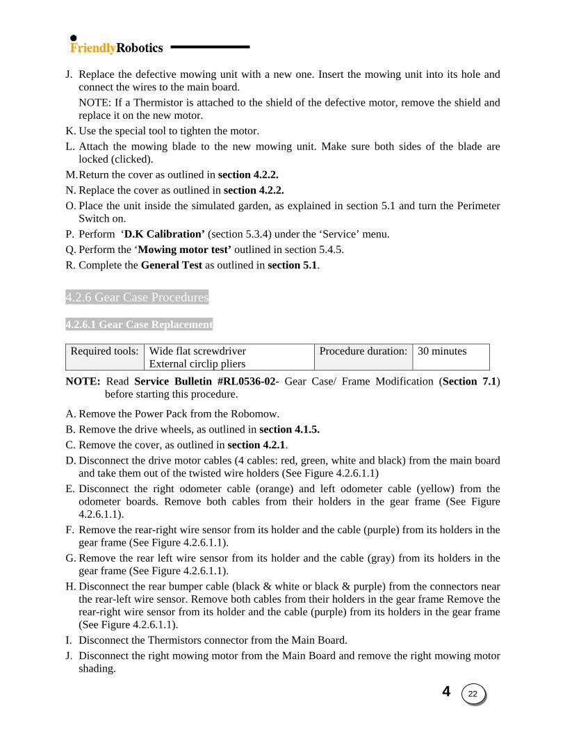
J. Replace the defective mowing unit with a new one. Insert the mowing unit into its hole and
connect the wires to the main board. NOTE: If a Thermistor is attached to the shield of the defective motor, remove the shield and replace it on the new motor.
K. Use the special tool to tighten the motor. L. Attach the mowing blade to the new mowing unit. Make sure both sides of the blade are
locked (clicked). M. Return the cover as outlined in section 4.2.2. N. Replace the cover as outlined in section 4.2.2. O. Place the unit inside the simulated garden, as explained in section 5.1 and turn the Perimeter
Switch on. P. Perform ‘D.K Calibration’ (section 5.3.4) under the ‘Service’ menu. Q. Perform the ‘Mowing motor test’ outlined in section 5.4.5. R. Complete the General Test as outlined in section 5.1.
4.2.6 Gear Case Procedures
4.2.6.1 Gear Case Replacement
Required tools: Wide flat screwdriver
External circlip pliers Procedure duration: 30 minutes
NOTE: Read Service Bulletin #RL0536-02- Gear Case/ Frame Modification (Section 7.1) before starting this procedure.
A. Remove the Power Pack from the Robomow. B. Remove the drive wheels, as outlined in section 4.1.5. C. Remove the cover, as outlined in section 4.2.1. D. Disconnect the drive motor cables (4 cables: red, green, white and black) from the main board
and take them out of the twisted wire holders (See Figure 4.2.6.1.1) E. Disconnect the right odometer cable (orange) and left odometer cable (yellow) from the
odometer boards. Remove both cables from their holders in the gear frame (See Figure 4.2.6.1.1).
F. Remove the rear-right wire sensor from its holder and the cable (purple) from its holders in the gear frame (See Figure 4.2.6.1.1).
G. Remove the rear left wire sensor from its holder and the cable (gray) from its holders in the gear frame (See Figure 4.2.6.1.1).
H. Disconnect the rear bumper cable (black & white or black & purple) from the connectors near the rear-left wire sensor. Remove both cables from their holders in the gear frame Remove the rear-right wire sensor from its holder and the cable (purple) from its holders in the gear frame (See Figure 4.2.6.1.1).
I. Disconnect the Thermistors connector from the Main Board. J. Disconnect the right mowing motor from the Main Board and remove the right mowing motor
shading.
4 22
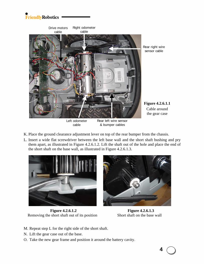
4 23
Left odometer cable
Rear left wire sensor & bumper cables
Rear right wire sensor cable
Right odometer cable
Drive motors cable
Figure 4.2.6.1.1Cable around the gear case
K. Place the ground clearance adjustment lever on top of the rear bumper from the chassis. L. Insert a wide flat screwdriver between the left base wall and the short shaft bushing and pry
them apart, as illustrated in Figure 4.2.6.1.2. Lift the shaft out of the hole and place the end of the short shaft on the base wall, as illustrated in Figure 4.2.6.1.3.
Figure 4.2.6.1.2 Figure 4.2.6.1.3 Removing the short shaft out of its position Short shaft on the base wall
M. Repeat step L for the right side of the short shaft. N. Lift the gear case out of the base. O. Take the new gear frame and position it around the battery cavity.
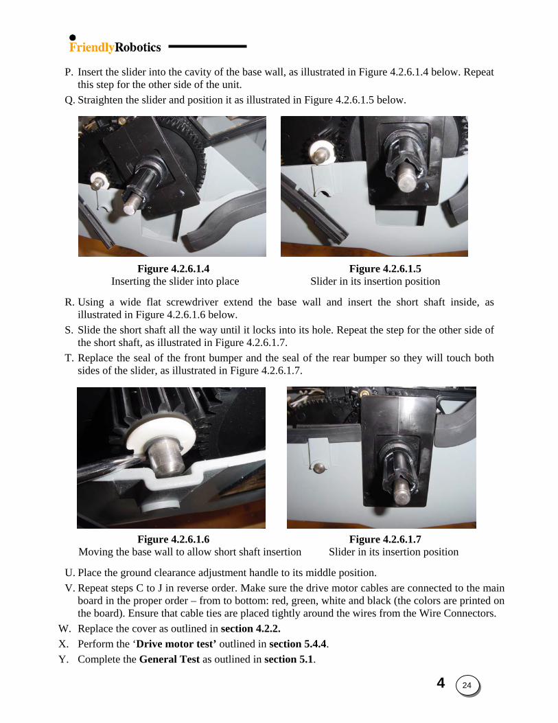
P. Insert the slider into the cavity of the base wall, as illustrated in Figure 4.2.6.1.4 below. Repeat this step for the other side of the unit.
Q. Straighten the slider and position it as illustrated in Figure 4.2.6.1.5 below.
Figure 4.2.6.1.4 Figure 4.2.6.1.5 Inserting the slider into place Slider in its insertion position
R. Using a wide flat screwdriver extend the base wall and insert the short shaft inside, as illustrated in Figure 4.2.6.1.6 below.
S. Slide the short shaft all the way until it locks into its hole. Repeat the step for the other side of the short shaft, as illustrated in Figure 4.2.6.1.7.
T. Replace the seal of the front bumper and the seal of the rear bumper so they will touch both sides of the slider, as illustrated in Figure 4.2.6.1.7.
Figure 4.2.6.1.6 Figure 4.2.6.1.7 Moving the base wall to allow short shaft insertion Slider in its insertion position
U. Place the ground clearance adjustment handle to its middle position. V. Repeat steps C to J in reverse order. Make sure the drive motor cables are connected to the main
board in the proper order – from to bottom: red, green, white and black (the colors are printed on the board). Ensure that cable ties are placed tightly around the wires from the Wire Connectors.
W. Replace the cover as outlined in section 4.2.2. X. Perform the ‘Drive motor test’ outlined in section 5.4.4. Y. Complete the General Test as outlined in section 5.1.
4 24
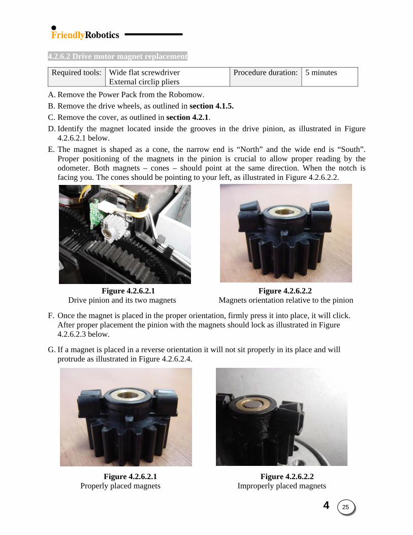
4.2.6.2 Drive motor magnet replacement
Required tools: Wide flat screwdriver External circlip pliers
Procedure duration: 5 minutes
A. Remove the Power Pack from the Robomow. B. Remove the drive wheels, as outlined in section 4.1.5. C. Remove the cover, as outlined in section 4.2.1. D. Identify the magnet located inside the grooves in the drive pinion, as illustrated in Figure
4.2.6.2.1 below. E. The magnet is shaped as a cone, the narrow end is “North” and the wide end is “South”.
Proper positioning of the magnets in the pinion is crucial to allow proper reading by the odometer. Both magnets – cones – should point at the same direction. When the notch is facing you. The cones should be pointing to your left, as illustrated in Figure 4.2.6.2.2.
Figure 4.2.6.2.1 Figure 4.2.6.2.2 Drive pinion and its two magnets Magnets orientation relative to the pinion
F. Once the magnet is placed in the proper orientation, firmly press it into place, it will click. After proper placement the pinion with the magnets should lock as illustrated in Figure 4.2.6.2.3 below.
G. If a magnet is placed in a reverse orientation it will not sit properly in its place and will protrude as illustrated in Figure 4.2.6.2.4.
Figure 4.2.6.2.1 Figure 4.2.6.2.2 Properly placed magnets Improperly placed magnets
4 25
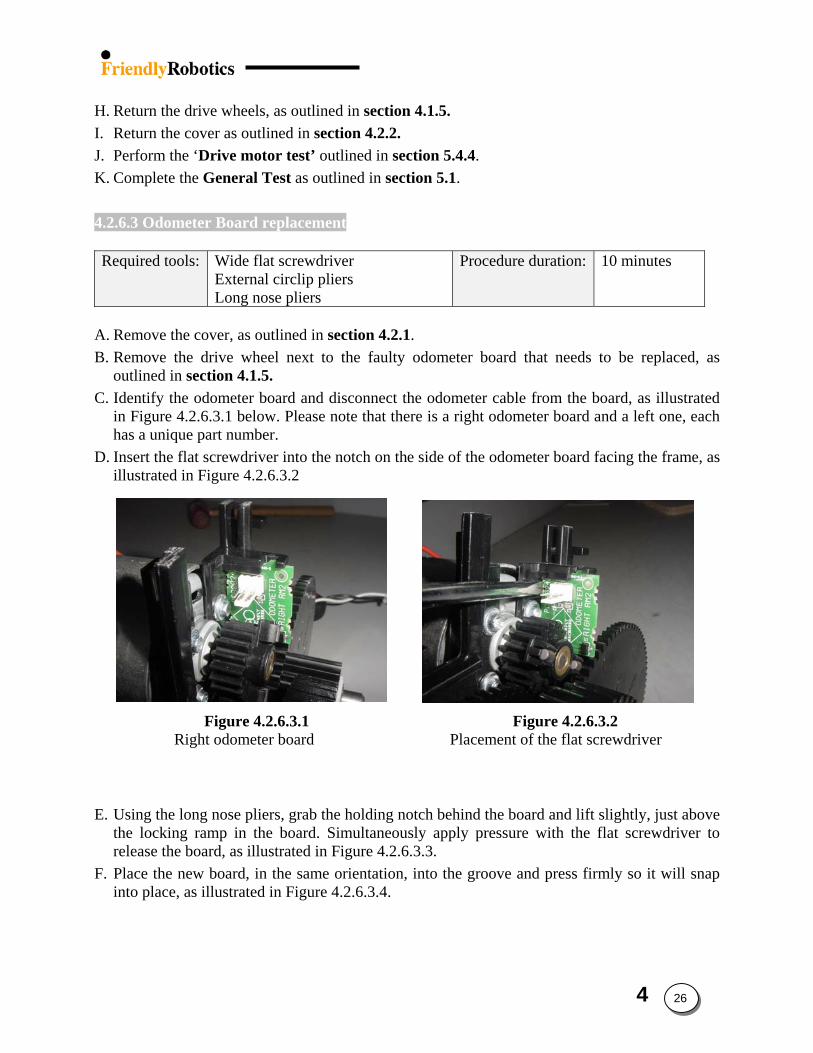
H. Return the drive wheels, as outlined in section 4.1.5. I. Return the cover as outlined in section 4.2.2. J. Perform the ‘Drive motor test’ outlined in section 5.4.4. K. Complete the General Test as outlined in section 5.1.
4.2.6.3 Odometer Board replacement
Required tools: Wide flat screwdriver
External circlip pliers Long nose pliers
Procedure duration: 10 minutes
A. Remove the cover, as outlined in section 4.2.1. B. Remove the drive wheel next to the faulty odometer board that needs to be replaced, as
outlined in section 4.1.5. C. Identify the odometer board and disconnect the odometer cable from the board, as illustrated
in Figure 4.2.6.3.1 below. Please note that there is a right odometer board and a left one, each has a unique part number.
D. Insert the flat screwdriver into the notch on the side of the odometer board facing the frame, as illustrated in Figure 4.2.6.3.2
Figure 4.2.6.3.1 Figure 4.2.6.3.2 Right odometer board Placement of the flat screwdriver
E. Using the long nose pliers, grab the holding notch behind the board and lift slightly, just above the locking ramp in the board. Simultaneously apply pressure with the flat screwdriver to release the board, as illustrated in Figure 4.2.6.3.3.
F. Place the new board, in the same orientation, into the groove and press firmly so it will snap into place, as illustrated in Figure 4.2.6.3.4.
4 26
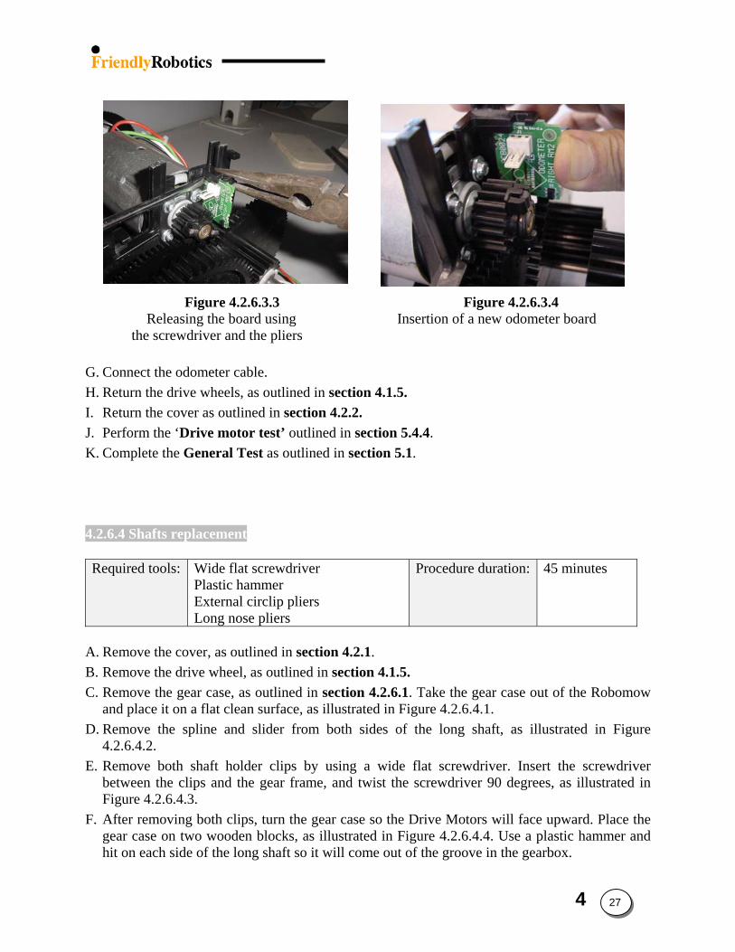
Figure 4.2.6.3.3 Figure 4.2.6.3.4 Releasing the board using Insertion of a new odometer board
the screwdriver and the pliers
G. Connect the odometer cable. H. Return the drive wheels, as outlined in section 4.1.5. I. Return the cover as outlined in section 4.2.2. J. Perform the ‘Drive motor test’ outlined in section 5.4.4. K. Complete the General Test as outlined in section 5.1.
4.2.6.4 Shafts replacement
Required tools: Wide flat screwdriver Plastic hammer External circlip pliers Long nose pliers
Procedure duration: 45 minutes
A. Remove the cover, as outlined in section 4.2.1. B. Remove the drive wheel, as outlined in section 4.1.5. C. Remove the gear case, as outlined in section 4.2.6.1. Take the gear case out of the Robomow
and place it on a flat clean surface, as illustrated in Figure 4.2.6.4.1. D. Remove the spline and slider from both sides of the long shaft, as illustrated in Figure
4.2.6.4.2. E. Remove both shaft holder clips by using a wide flat screwdriver. Insert the screwdriver
between the clips and the gear frame, and twist the screwdriver 90 degrees, as illustrated in Figure 4.2.6.4.3.
F. After removing both clips, turn the gear case so the Drive Motors will face upward. Place the gear case on two wooden blocks, as illustrated in Figure 4.2.6.4.4. Use a plastic hammer and hit on each side of the long shaft so it will come out of the groove in the gearbox.
4 27
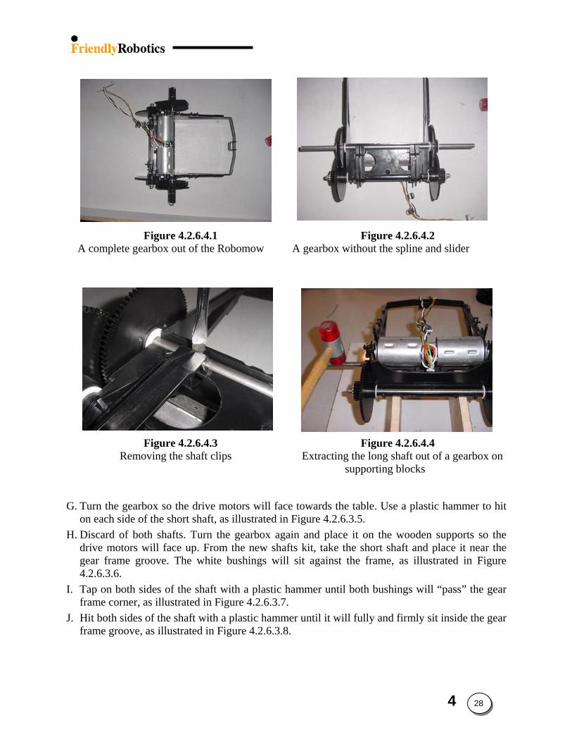
Figure 4.2.6.4.1 Figure 4.2.6.4.2 A complete gearbox out of the Robomow A gearbox without the spline and slider
Figure 4.2.6.4.3 Figure 4.2.6.4.4 Removing the shaft clips Extracting the long shaft out of a gearbox on
supporting blocks
G. Turn the gearbox so the drive motors will face towards the table. Use a plastic hammer to hit
on each side of the short shaft, as illustrated in Figure 4.2.6.3.5. H. Discard of both shafts. Turn the gearbox again and place it on the wooden supports so the
drive motors will face up. From the new shafts kit, take the short shaft and place it near the gear frame groove. The white bushings will sit against the frame, as illustrated in Figure 4.2.6.3.6.
I. Tap on both sides of the shaft with a plastic hammer until both bushings will “pass” the gear frame corner, as illustrated in Figure 4.2.6.3.7.
J. Hit both sides of the shaft with a plastic hammer until it will fully and firmly sit inside the gear frame groove, as illustrated in Figure 4.2.6.3.8.
4 28
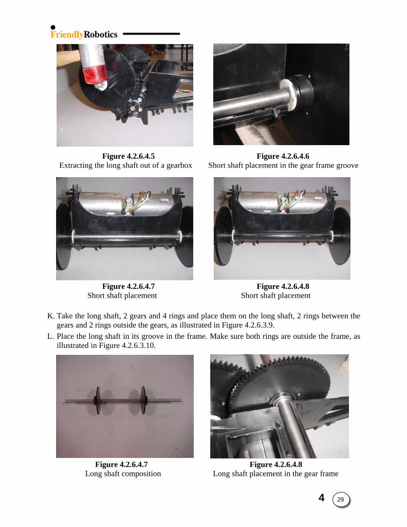
Figure 4.2.6.4.5 Figure 4.2.6.4.6 Extracting the long shaft out of a gearbox Short shaft placement in the gear frame groove
Figure 4.2.6.4.7 Figure 4.2.6.4.8 Short shaft placement Short shaft placement
K. Take the long shaft, 2 gears and 4 rings and place them on the long shaft, 2 rings between the
gears and 2 rings outside the gears, as illustrated in Figure 4.2.6.3.9. L. Place the long shaft in its groove in the frame. Make sure both rings are outside the frame, as
illustrated in Figure 4.2.6.3.10.
Figure 4.2.6.4.7 Figure 4.2.6.4.8 Long shaft composition Long shaft placement in the gear frame
4 29
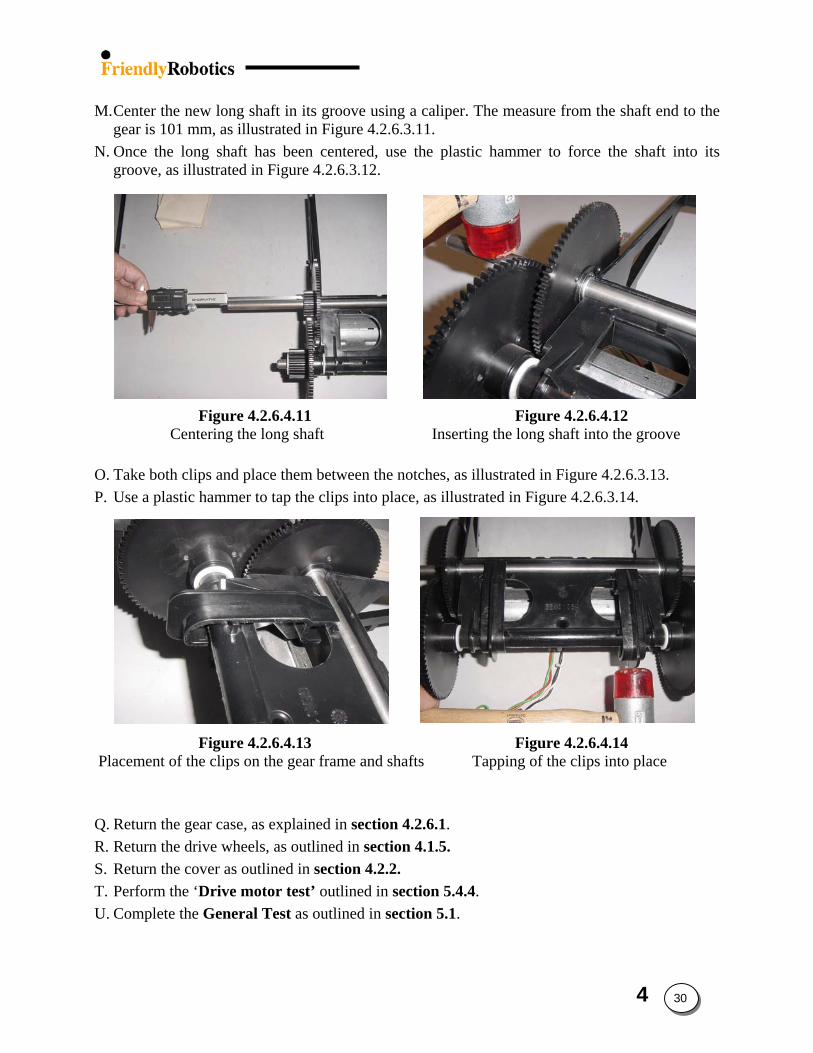
M. Center the new long shaft in its groove using a caliper. The measure from the shaft end to the
gear is 101 mm, as illustrated in Figure 4.2.6.3.11. N. Once the long shaft has been centered, use the plastic hammer to force the shaft into its
groove, as illustrated in Figure 4.2.6.3.12. Figure 4.2.6.4.11 Figure 4.2.6.4.12
Centering the long shaft Inserting the long shaft into the groove O. Take both clips and place them between the notches, as illustrated in Figure 4.2.6.3.13. P. Use a plastic hammer to tap the clips into place, as illustrated in Figure 4.2.6.3.14.
Figure 4.2.6.4.13 Figure 4.2.6.4.14
Placement of the clips on the gear frame and shafts Tapping of the clips into place
Q. Return the gear case, as explained in section 4.2.6.1. R. Return the drive wheels, as outlined in section 4.1.5. S. Return the cover as outlined in section 4.2.2. T. Perform the ‘Drive motor test’ outlined in section 5.4.4. U. Complete the General Test as outlined in section 5.1.
4 30
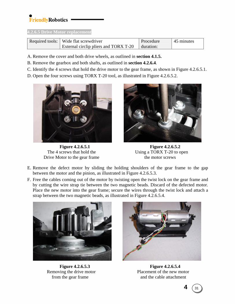
4.2.6.5 Drive Motor replacement
Required tools: Wide flat screwdriver External circlip pliers and TORX T-20
Procedure duration:
45 minutes
A. Remove the cover and both drive wheels, as outlined in section 4.1.5. B. Remove the gearbox and both shafts, as outlined in section 4.2.6.4. C. Identify the 4 screws that hold the drive motor to the gear frame, as shown in Figure 4.2.6.5.1. D. Open the four screws using TORX T-20 tool, as illustrated in Figure 4.2.6.5.2.
Figure 4.2.6.5.1 Figure 4.2.6.5.2 The 4 screws that hold the Using a TORX T-20 to open
Drive Motor to the gear frame the motor screws
E. Remove the defect motor by sliding the holding shoulders of the gear frame to the gap between the motor and the pinion, as illustrated in Figure 4.2.6.5.3.
F. Free the cables coming out of the motor by twisting open the twist lock on the gear frame and by cutting the wire strap tie between the two magnetic beads. Discard of the defected motor. Place the new motor into the gear frame; secure the wires through the twist lock and attach a strap between the two magnetic beads, as illustrated in Figure 4.2.6.5.4.
Figure 4.2.6.5.3 Figure 4.2.6.5.4 Removing the drive motor Placement of the new motor
from the gear frame and the cable attachment
4 31
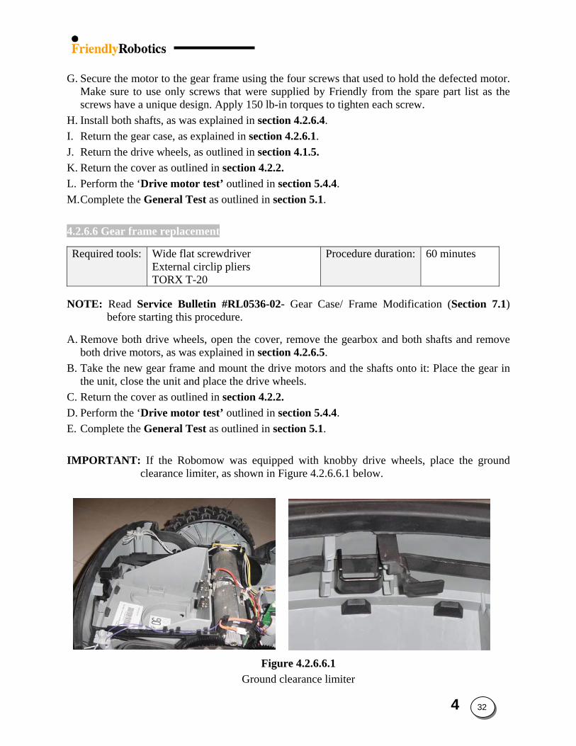
G. Secure the motor to the gear frame using the four screws that used to hold the defected motor.
Make sure to use only screws that were supplied by Friendly from the spare part list as the screws have a unique design. Apply 150 lb-in torques to tighten each screw.
H. Install both shafts, as was explained in section 4.2.6.4. I. Return the gear case, as explained in section 4.2.6.1. J. Return the drive wheels, as outlined in section 4.1.5. K. Return the cover as outlined in section 4.2.2. L. Perform the ‘Drive motor test’ outlined in section 5.4.4. M. Complete the General Test as outlined in section 5.1.
4.2.6.6 Gear frame replacement
Required tools: Wide flat screwdriver External circlip pliers TORX T-20
Procedure duration: 60 minutes
NOTE: Read Service Bulletin #RL0536-02- Gear Case/ Frame Modification (Section 7.1) before starting this procedure.
A. Remove both drive wheels, open the cover, remove the gearbox and both shafts and remove both drive motors, as was explained in section 4.2.6.5.
B. Take the new gear frame and mount the drive motors and the shafts onto it: Place the gear in the unit, close the unit and place the drive wheels.
C. Return the cover as outlined in section 4.2.2. D. Perform the ‘Drive motor test’ outlined in section 5.4.4. E. Complete the General Test as outlined in section 5.1.
IMPORTANT: If the Robomow was equipped with knobby drive wheels, place the ground
clearance limiter, as shown in Figure 4.2.6.6.1 below.
Figure 4.2.6.6.1 Ground clearance limiter
4 32
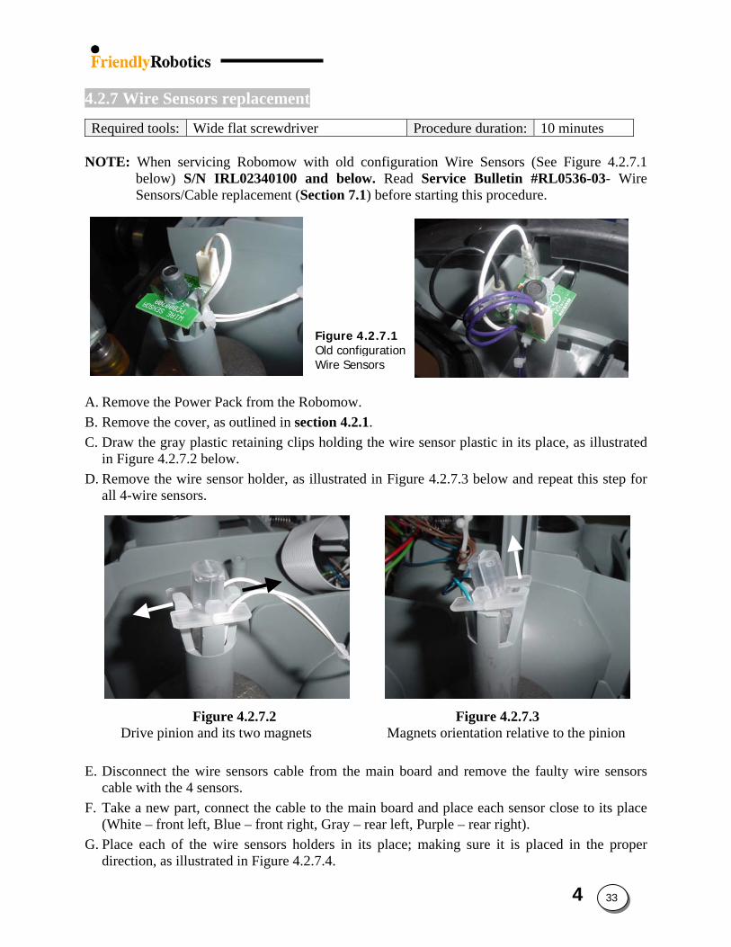
4.2.7 Wire Sensors replacement
Required tools: Wide flat screwdriver Procedure duration: 10 minutes
NOTE: When servicing Robomow with old configuration Wire Sensors (See Figure 4.2.7.1
below) S/N IRL02340100 and below. Read Service Bulletin #RL0536-03- Wire Sensors/Cable replacement (Section 7.1) before starting this procedure.
A. Remove the Power Pack from the RB. Remove the cover, as outlined in secC. Draw the gray plastic retaining clip
in Figure 4.2.7.2 below. D. Remove the wire sensor holder, as
all 4-wire sensors.
Figure 4.2.7.2 Drive pinion and its two magnets
E. Disconnect the wire sensors cable cable with the 4 sensors.
F. Take a new part, connect the cable (White – front left, Blue – front righ
G. Place each of the wire sensors holdirection, as illustrated in Figure 4.2
Figure 4.2.7.1 Old configuration Wire Sensors
obomow. tion 4.2.1.
s holding the wire sensor plastic in its place, as illustrated
illustrated in Figure 4.2.7.3 below and repeat this step for
Figure 4.2.7.3 Magnets orientation relative to the pinion
from the main board and remove the faulty wire sensors
to the main board and place each sensor close to its place t, Gray – rear left, Purple – rear right). ders in its place; making sure it is placed in the proper .7.4.
4 33
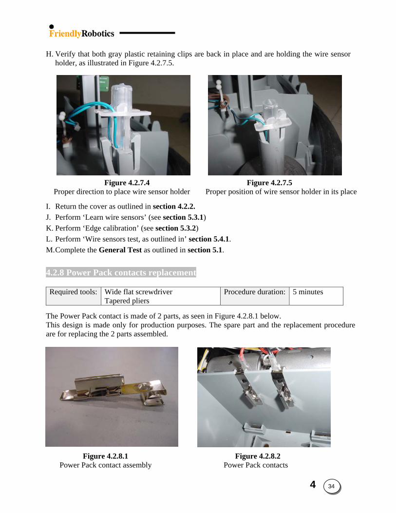
H. Verify that both gray plastic retaining clips are back in place and are holding the wire sensor
holder, as illustrated in Figure 4.2.7.5.
Figure 4.2.7.4 Figure 4.2.7.5 Proper direction to place wire sensor holder Proper position of wire sensor holder in its place
I. Return the cover as outlined in section 4.2.2. J. Perform ‘Learn wire sensors’ (see section 5.3.1) K. Perform ‘Edge calibration’ (see section 5.3.2) L. Perform ‘Wire sensors test, as outlined in’ section 5.4.1. M. Complete the General Test as outlined in section 5.1.
4.2.8 Power Pack contacts replacement
Required tools: Wide flat screwdriver
Tapered pliers Procedure duration: 5 minutes
The Power Pack contact is made of 2 parts, as seen in Figure 4.2.8.1 below. This design is made only for production purposes. The spare part and the replacement procedure are for replacing the 2 parts assembled.
Figure 4.2.8.1 Figure 4.2.8.2 Power Pack contact assembly Power Pack contacts
4 34
A. Remove the Power Pack from the Robomow. B. Remove the cover, as outlined in section 4.2.1 and expose the power pack contacts, as
illustrated in Figure 4.2.8.2. C. Disconnect the damaged power pack contact from its lead and replace it with a new one.
Ensure the leads are connected correctly – red wire on LH contact, black on RH. D. Return the cover as outlined in section 4.2.2. E. Test the functionality of the Robomow by replacing the Power Pack and observing that the
unit “wakes up”. F. Complete the General Test as outlined in section 5.1.
4 35
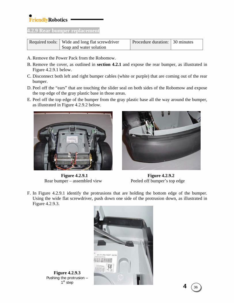
4 36
4.2.9 Rear bumper replacement
Required tools: Wide and long flat screwdriver
Soap and water solution Procedure duration: 30 minutes
A. Remove the Power Pack from the Robomow. B. Remove the cover, as outlined in section 4.2.1 and expose the rear bumper, as illustrated in
Figure 4.2.9.1 below. C. Disconnect both left and right bumper cables (white or purple) that are coming out of the rear
bumper. D. Peel off the “ears” that are touching the slider seal on both sides of the Robomow and expose
the top edge of the gray plastic base in those areas. E. Peel off the top edge of the bumper from the gray plastic base all the way around the bumper,
as illustrated in Figure 4.2.9.2 below.
Figure 4.2.9.1 Figure 4.2.9.2 Rear bumper – assembled view Peeled off bumper’s top edge
Figure 4.2.9.3 Pushing the protrusion –
1st step
F. In Figure 4.2.9.1 identify the protrusions that are holding the bottom edge of the bumper. Using the wide flat screwdriver, push down one side of the protrusion down, as illustrated in Figure 4.2.9.3.
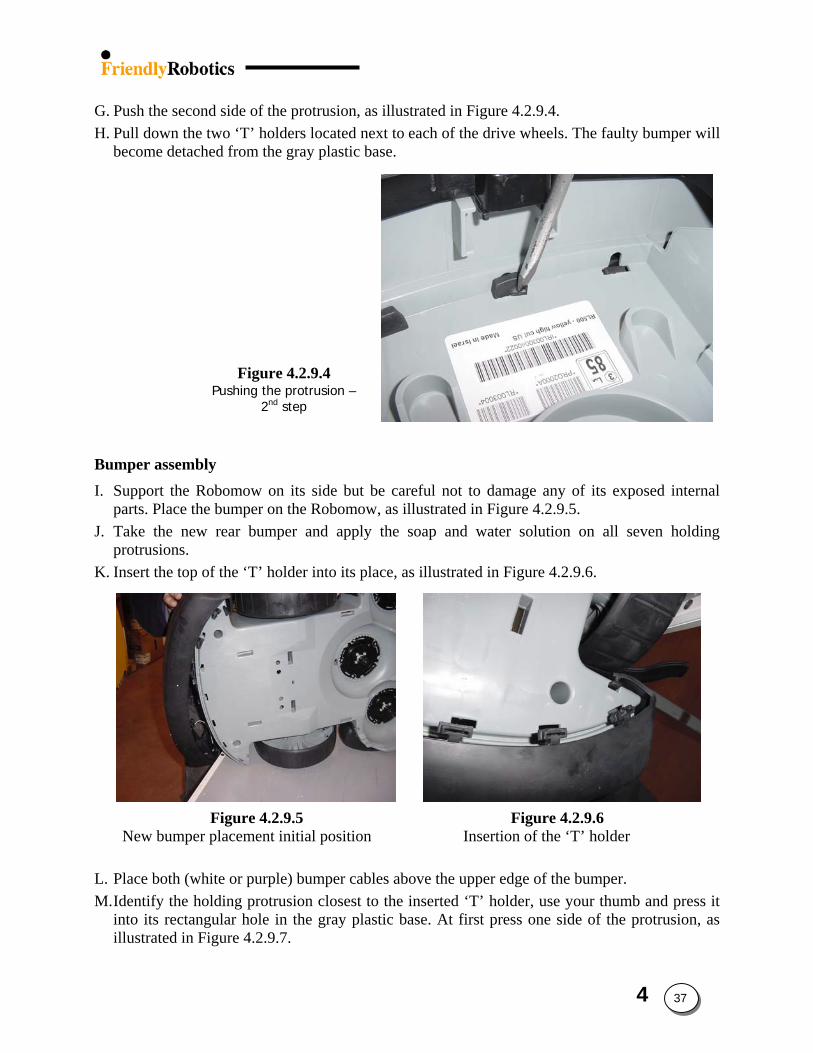
G. Push the second side of the protrusion, as illustrated in Figure 4.2.9.4.
Figure 4.2.9.4 Pushing the protrusion –
2nd step
H. Pull down the two ‘T’ holders located next to each of the drive wheels. The faulty bumper will become detached from the gray plastic base.
Bumper assembly I. Support the Robomow on its side but be careful not to damage any of its exposed internal
parts. Place the bumper on the Robomow, as illustrated in Figure 4.2.9.5. J. Take the new rear bumper and apply the soap and water solution on all seven holding
protrusions. K. Insert the top of the ‘T’ holder into its place, as illustrated in Figure 4.2.9.6.
Figure 4.2.9.5 Figure 4.2.9.6 New bumper placement initial position Insertion of the ‘T’ holder
L. Place both (white or purple) bumper cables above the upper edge of the bumper. M. Identify the holding protrusion closest to the inserted ‘T’ holder, use your thumb and press it
into its rectangular hole in the gray plastic base. At first press one side of the protrusion, as illustrated in Figure 4.2.9.7.
4 37
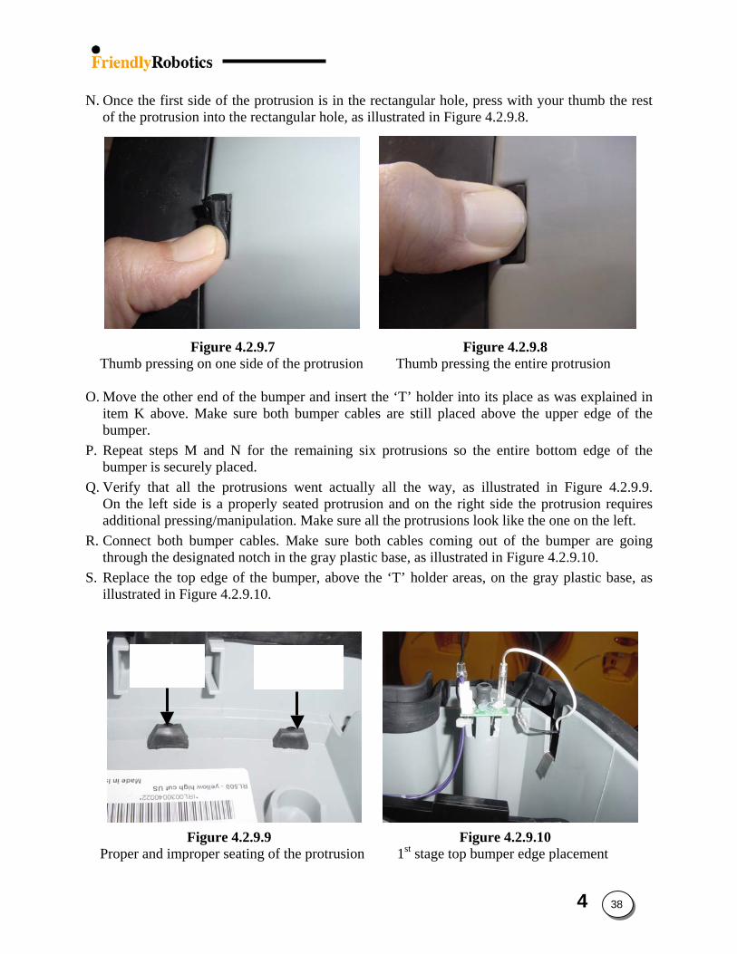
N. Once the first side of the protrusion is in the rectangular hole, press with your thumb the rest
of the protrusion into the rectangular hole, as illustrated in Figure 4.2.9.8.
Figure 4.2.9.7 Figure 4.2.9.8 Thumb pressing on one side of the protrusion Thumb pressing the entire protrusion O. Move the other end of the bumper and insert the ‘T’ holder into its place as was explained in
item K above. Make sure both bumper cables are still placed above the upper edge of the bumper.
P. Repeat steps M and N for the remaining six protrusions so the entire bottom edge of the bumper is securely placed.
Q. Verify that all the protrusions went actually all the way, as illustrated in Figure 4.2.9.9. On the left side is a properly seated protrusion and on the right side the protrusion requires additional pressing/manipulation. Make sure all the protrusions look like the one on the left.
R. Connect both bumper cables. Make sure both cables coming out of the bumper are going through the designated notch in the gray plastic base, as illustrated in Figure 4.2.9.10.
Proper seating
Improper seating
S. Replace the top edge of the bumper, above the ‘T’ holder areas, on the gray plastic base, as illustrated in Figure 4.2.9.10.
Figure 4.2.9.9 Figure 4.2.9.10 Proper and improper seating of the protrusion 1st stage top bumper edge placement
4 38
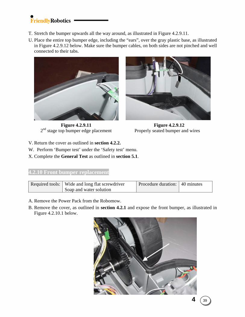
T. Stretch the bumper upwards all the way around, as illustrated in Figure 4.2.9.11. U. Place the entire top bumper edge, including the “ears”, over the gray plastic base, as illustrated
in Figure 4.2.9.12 below. Make sure the bumper cables, on both sides are not pinched and well connected to their tabs.
Figure 4.2.9.11 Figure 4.2.9.12 2nd stage top bumper edge placement Properly seated bumper and wires
V. Return the cover as outlined in section 4.2.2. W. Perform ‘Bumper test’ under the ‘Safety test’ menu. X. Complete the General Test as outlined in section 5.1.
4.2.10 Front bumper replacement
Required tools: Wide and long flat screwdriver Soap and water solution
Procedure duration: 40 minutes
A. Remove the Power Pack from the Robomow.
Front Bumper ‘Ear’
Figure 4.2.10.1 Front Bumper
B. Remove the cover, as outlined in section 4.2.1 and expose the front bumper, as illustrated in Figure 4.2.10.1 below.
4 39
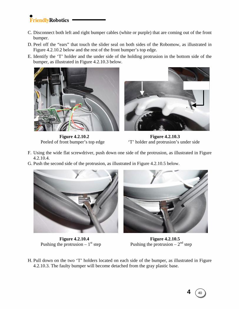
C. Disconnect both left and right bumper cables (white or purple) that are coming out of the front
bumper. D. Peel off the “ears” that touch the slider seal on both sides of the Robomow, as illustrated in
Figure 4.2.10.2 below and the rest of the front bumper’s top edge.
Underside of holding protrusion
‘T’ holder
E. Identify the ‘T’ holder and the under side of the holding protrusion in the bottom side of the bumper, as illustrated in Figure 4.2.10.3 below.
Figure 4.2.10.2 Figure 4.2.10.3 Peeled of front bumper’s top edge ‘T’ holder and protrusion’s under side F. Using the wide flat screwdriver, push down one side of the protrusion, as illustrated in Figure
4.2.10.4. G. Push the second side of the protrusion, as illustrated in Figure 4.2.10.5 below.
Figure 4.2.10.4 Figure 4.2.10.5 Pushing the protrusion – 1st step Pushing the protrusion – 2nd step H. Pull down on the two ‘T’ holders located on each side of the bumper, as illustrated in Figure
4.2.10.3. The faulty bumper will become detached from the gray plastic base.
4 40
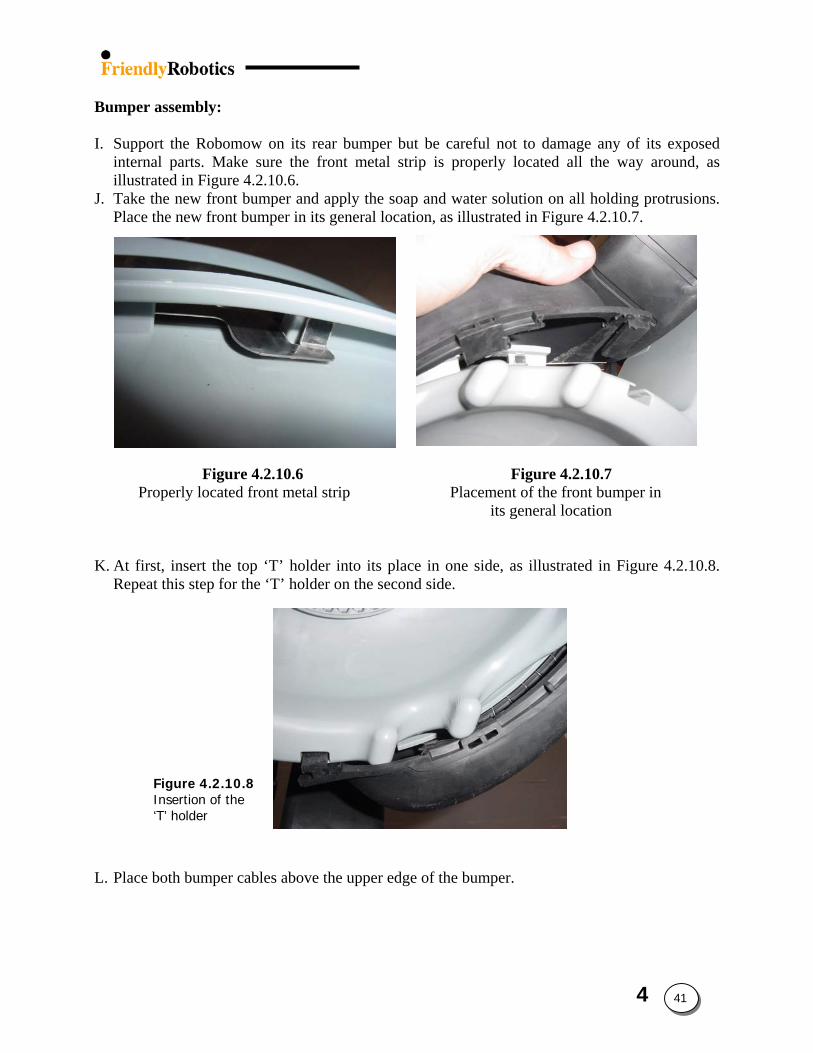
Bumper assembly:
I. Support the Robomow on its rear bumper but be careful not to damage any of its exposed
internal parts. Make sure the front metal strip is properly located all the way around, as illustrated in Figure 4.2.10.6.
J. Take the new front bumper and apply the soap and water solution on all holding protrusions. Place the new front bumper in its general location, as illustrated in Figure 4.2.10.7.
Figure 4.2.10.6 Figure 4.2.10.7 Properly located front metal strip Placement of the front bumper in
its general location
Figure 4.2.10.8 Insertion of the ‘T’ holder
K. At first, insert the top ‘T’ holder into its place in one side, as illustrated in Figure 4.2.10.8. Repeat this step for the ‘T’ holder on the second side.
L. Place both bumper cables above the upper edge of the bumper.
4 41
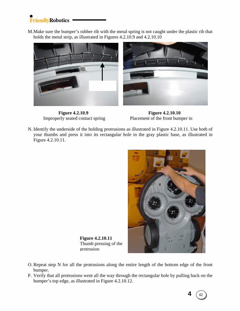
Plastic rib
M. Make sure the bumper’s rubber rib with the metal spring is not caught under the plastic rib that holds the metal strip, as illustrated in Figures 4.2.10.9 and 4.2.10.10
Figure 4.2.10.9 Figure 4.2.10.10 Improperly seated contact spring Placement of the front bumper in
N. Identify the underside of the holding protrusions as illustrated in Figure 4.2.10.11. Use both of
your thumbs and press it into its rectangular hole in the gray plastic base, as illustrated in Figure 4.2.10.11.
Figure 4.2.10.11 Thumb pressing of the protrusion
O. Repeat step N for all the protrusions along the entire length of the bottom edge of the front bumper.
P. Verify that all protrusions went all the way through the rectangular hole by pulling back on the bumper’s top edge, as illustrated in Figure 4.2.10.12.
4 42
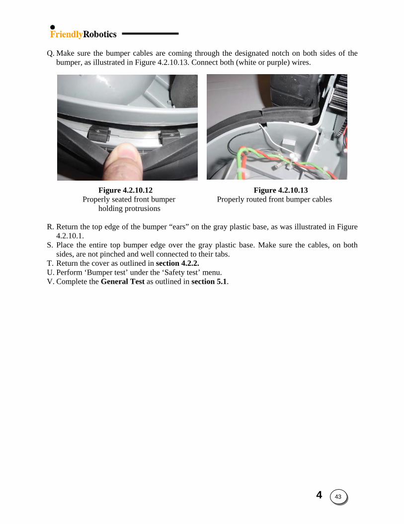
Q. Make sure the bumper cables are coming through the designated notch on both sides of the
bumper, as illustrated in Figure 4.2.10.13. Connect both (white or purple) wires.
Figure 4.2.10.12 Figure 4.2.10.13 Properly seated front bumper Properly routed front bumper cables
holding protrusions
R. Return the top edge of the bumper “ears” on the gray plastic base, as was illustrated in Figure 4.2.10.1.
S. Place the entire top bumper edge over the gray plastic base. Make sure the cables, on both sides, are not pinched and well connected to their tabs.
T. Return the cover as outlined in section 4.2.2. U. Perform ‘Bumper test’ under the ‘Safety test’ menu. V. Complete the General Test as outlined in section 5.1.
4 43
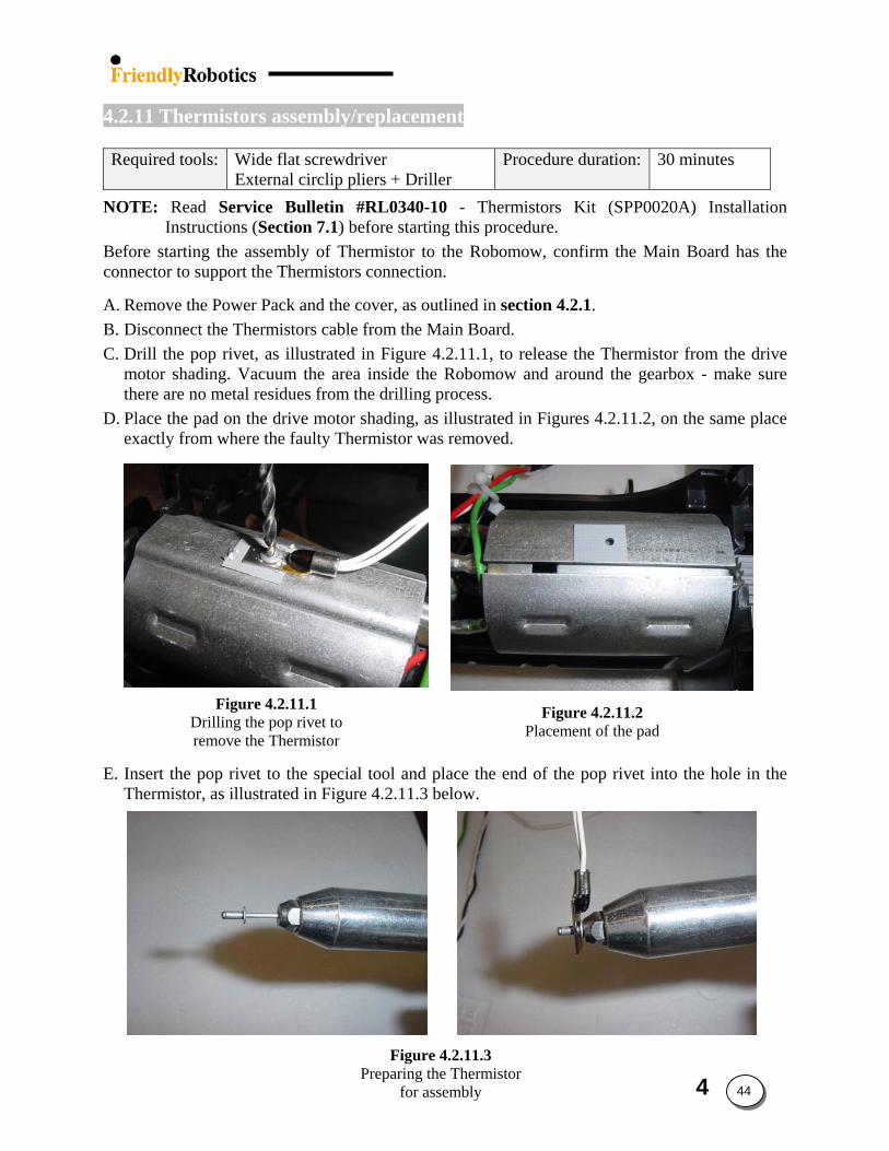
4 44
4.2.11 Thermistors assembly/replacement
Required tools: Wide flat screwdriver
External circlip pliers + Driller Procedure duration: 30 minutes
NOTE: Read Service Bulletin #RL0340-10 - Thermistors Kit (SPP0020A) Installation Instructions (Section 7.1) before starting this procedure.
Before starting the assembly of Thermistor to the Robomow, confirm the Main Board has the connector to support the Thermistors connection. A. Remove the Power Pack and the cover, as outlined in section 4.2.1. B. Disconnect the Thermistors cable from the Main Board. C. Drill the pop rivet, as illustrated in Figure 4.2.11.1, to release the Thermistor from the drive
motor shading. Vacuum the area inside the Robomow and around the gearbox - make sure there are no metal residues from the drilling process.
D. Place the pad on the drive motor shading, as illustrated in Figures 4.2.11.2, on the same place exactly from where the faulty Thermistor was removed.
Figure 4.2.11.1 Drilling the pop rivet to remove the Thermistor
Figure 4.2.11.2 Placement of the pad
E. Insert the pop rivet to the special tool and place the end of the pop rivet into the hole in the Thermistor, as illustrated in Figure 4.2.11.3 below.
Figure 4.2.11.3 Preparing the Thermistor
for assembly
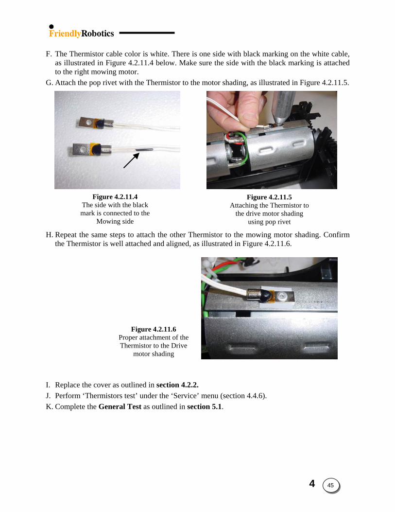
F. The Thermistor cable color is white. There is one side with black marking on the white cable,
as illustrated in Figure 4.2.11.4 below. Make sure the side with the black marking is attached to the right mowing motor.
Mowing side
G. Attach the pop rivet with the Thermistor to the motor shading, as illustrated in Figure 4.2.11.5.
Figure 4.2.11.4 The side with the black mark is connected to the
Mowing side
Figure 4.2.11.5 Attaching the Thermistor to
the drive motor shading using pop rivet
H. Repeat the same steps to attach the other Thermistor to the mowing motor shading. Confirm the Thermistor is well attached and aligned, as illustrated in Figure 4.2.11.6.
Figure 4.2.11.6 Proper attachment of the Thermistor to the Drive
motor shading
I. Replace the cover as outlined in section 4.2.2. J. Perform ‘Thermistors test’ under the ‘Service’ menu (section 4.4.6). K. Complete the General Test as outlined in section 5.1.
4 45
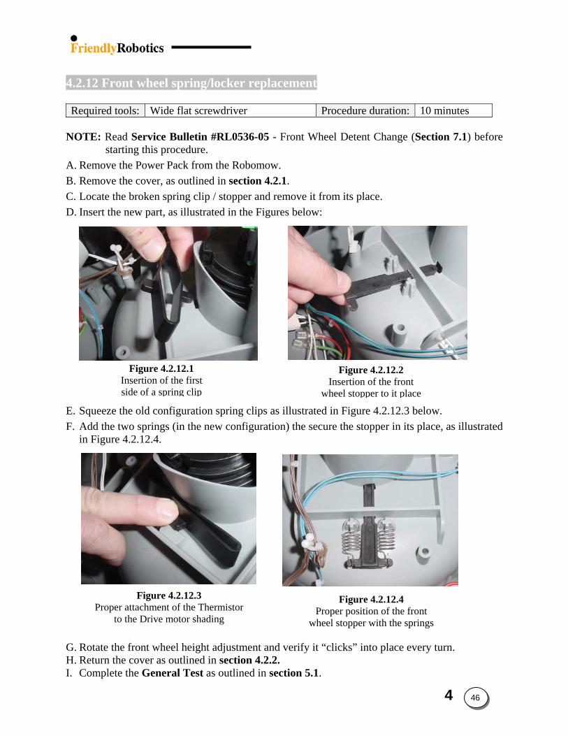
4.2.12 Front wheel spring/locker replacement
Required tools: Wide flat screwdriver Procedure duration: 10 minutes
NOTE: Read Service Bulletin #RL0536-05 - Front Wheel Detent Change (Section 7.1) before
starting this procedure. A. Remove the Power Pack from the Robomow. B. Remove the cover, as outlined in section 4.2.1. C. Locate the broken spring clip / stopper and remove it from its place. D. Insert the new part, as illustrated in the Figures below:
Is
Inwh
E. Squeeze thF. Add the tw
in Figure 4
Proper to
G. Rotate theH. Return theI. Complete
Figure 4.2.12.1 nsertion of the first ide of a spring clip
e old configuration spring clips as illustrated io springs (in the new configuration) the secure.2.12.4.
Figure 4.2.12.3 attachment of the Thermistor the Drive motor shading
Propwheel
front wheel height adjustment and verify it “cl cover as outlined in section 4.2.2. the General Test as outlined in section 5.1.
Figure 4.2.12.2 sertion of the front
eel stopper to it place
n Figure 4.2.12.3 below. the stopper in its place, as illustrated
Figure 4.2.12.4 er position of the front stopper with the springs
icks” into place every turn.
4 46
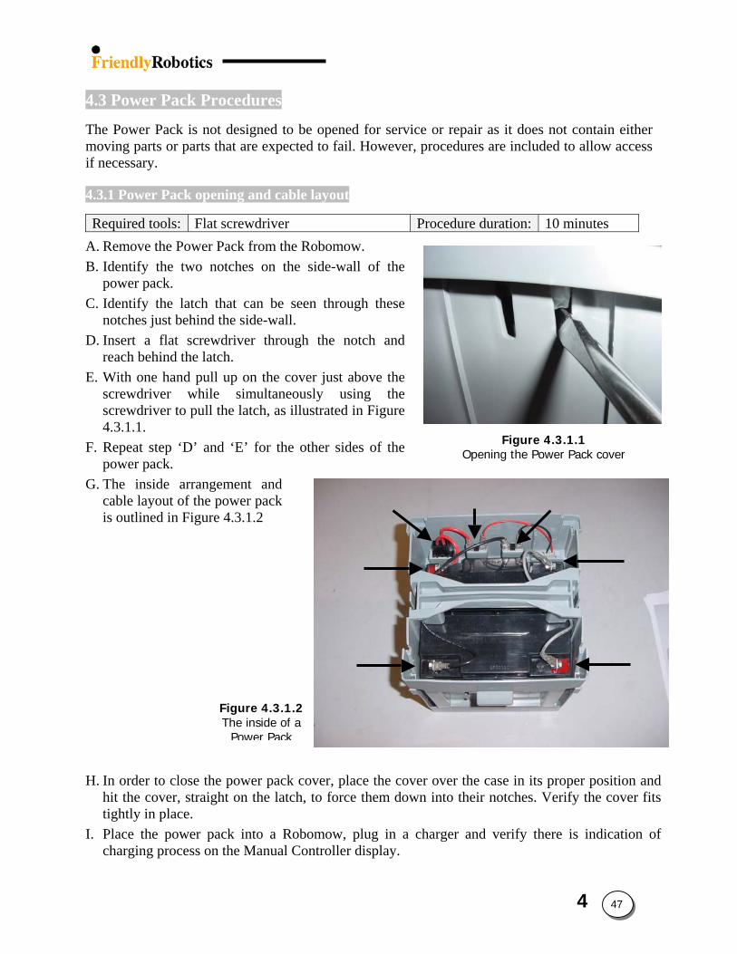
4.3 Power Pack Procedures
The Power Pack is not designed to be opened for service or repair as it does not contain either moving parts or parts that are expected to fail. However, procedures are included to allow access if necessary.
4.3.1 Power Pack opening and cable layout
Required tools: Flat screwdriver Procedure duration: 10 minutes
A. Remove the Power Pack from the Robomow. B. Identify the two notches on the side-wall of the
power pack. C. Identify the latch that can be seen through these
notches just behind the side-wall. D. Insert a flat screwdriver through the notch and
reach behind the latch. E. With one hand pull up on the cover just above the
screwdriver while simultaneously using the screwdriver to pull the latch, as illustrated in Figure 4.3.1.1.
Figure 4.3.1.1 Opening the Power Pack cover F. Repeat step ‘D’ and ‘E’ for the other sides of the
power pack.
Power Pack fuse
(+) Terminal
(-) Terminal
(+)
(+)
(-)
(-)
Figure 4.3.1.2The inside of a
Power Pack
G. The inside arrangement and cable layout of the power pack is outlined in Figure 4.3.1.2
H. In order to close the power pack cover, place the cover over the case in its proper position and
hit the cover, straight on the latch, to force them down into their notches. Verify the cover fits tightly in place.
I. Place the power pack into a Robomow, plug in a charger and verify there is indication of charging process on the Manual Controller display.
4 47
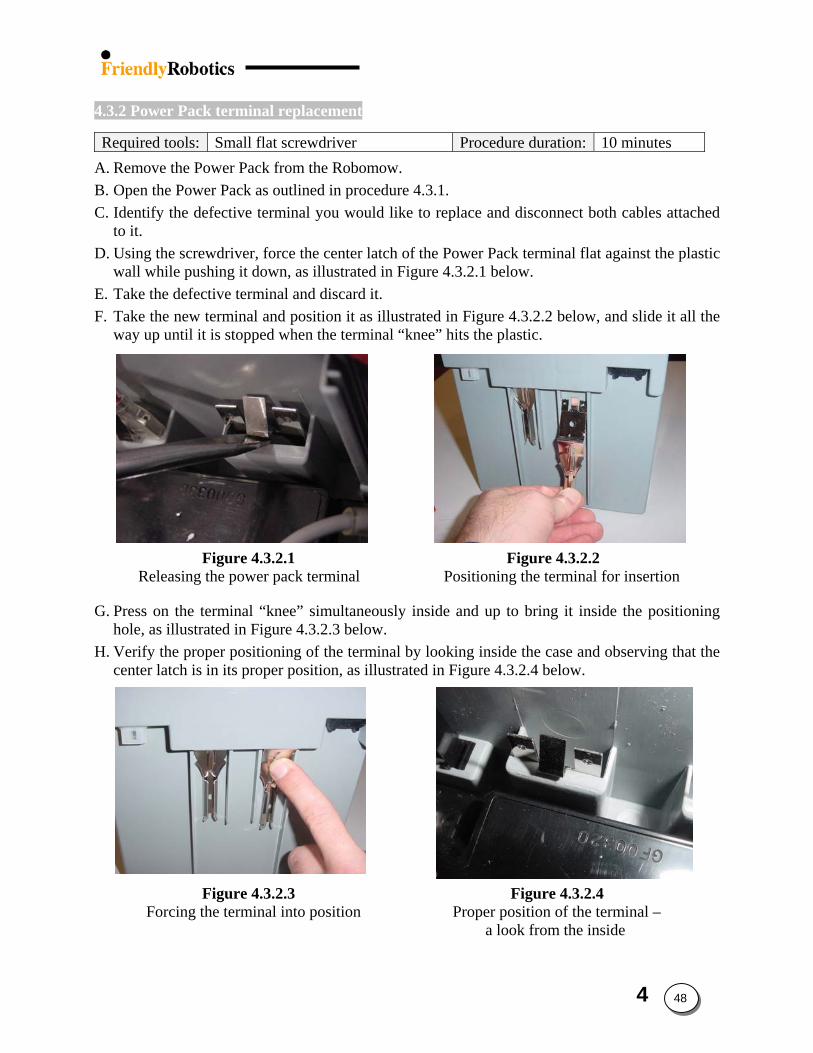
4.3.2 Power Pack terminal replacement
Required tools: Small flat screwdriver Procedure duration: 10 minutes
A. Remove the Power Pack from the Robomow. B. Open the Power Pack as outlined in procedure 4.3.1. C. Identify the defective terminal you would like to replace and disconnect both cables attached
to it. D. Using the screwdriver, force the center latch of the Power Pack terminal flat against the plastic
wall while pushing it down, as illustrated in Figure 4.3.2.1 below. E. Take the defective terminal and discard it. F. Take the new terminal and position it as illustrated in Figure 4.3.2.2 below, and slide it all the
way up until it is stopped when the terminal “knee” hits the plastic.
Figure 4.3.2.1 Figure 4.3.2.2 Releasing the power pack terminal Positioning the terminal for insertion
G. Press on the terminal “knee” simultaneously inside and up to bring it inside the positioning hole, as illustrated in Figure 4.3.2.3 below.
H. Verify the proper positioning of the terminal by looking inside the case and observing that the center latch is in its proper position, as illustrated in Figure 4.3.2.4 below.
Figure 4.3.2.3 Figure 4.3.2.4 Forcing the terminal into position Proper position of the terminal – a look from the inside
4 48

I. Connect both cables to the power pack terminal, as illustrated in Figure 4.3.2.1. Ensure correct
polarity. J. Verify the functionality of the repair by placing the power pack in a Robomow and observing
it turning on. K. Close the case cover as illustrated in procedure 4.3.1.
4 49
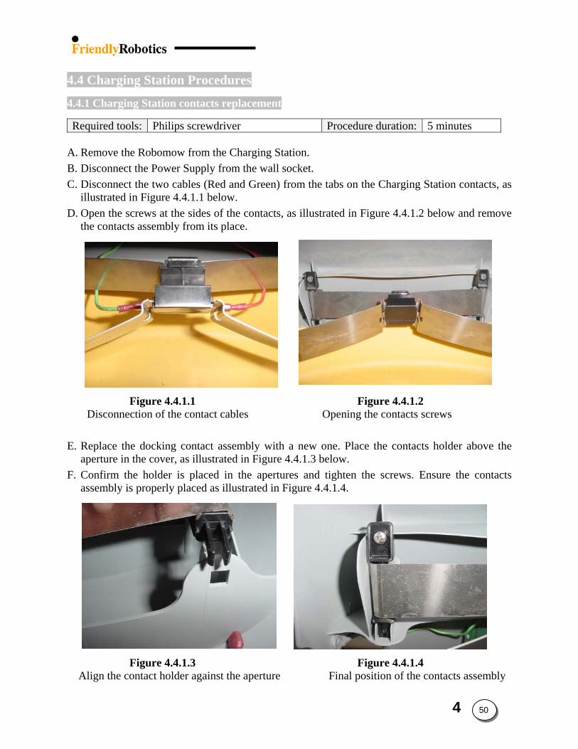
4.4 Charging Station Procedures
4.4.1 Charging Station contacts replacement
Required tools: Philips screwdriver Procedure duration: 5 minutes
A. Remove the Robomow from the Charging Station. B. Disconnect the Power Supply from the wall socket. C. Disconnect the two cables (Red and Green) from the tabs on the Charging Station contacts, as
illustrated in Figure 4.4.1.1 below. D. Open the screws at the sides of the contacts, as illustrated in Figure 4.4.1.2 below and remove
the contacts assembly from its place.
Figure 4.4.1.1 Figure 4.4.1.2 Disconnection of the contact cables Opening the contacts screws
E. Replace the docking contact assembly with a new one. Place the contacts holder above the
aperture in the cover, as illustrated in Figure 4.4.1.3 below. F. Confirm the holder is placed in the apertures and tighten the screws. Ensure the contacts
assembly is properly placed as illustrated in Figure 4.4.1.4.
Figure 4.4.1.3 Figure 4.4.1.4 Align the contact holder against the aperture Final position of the contacts assembly
4 50
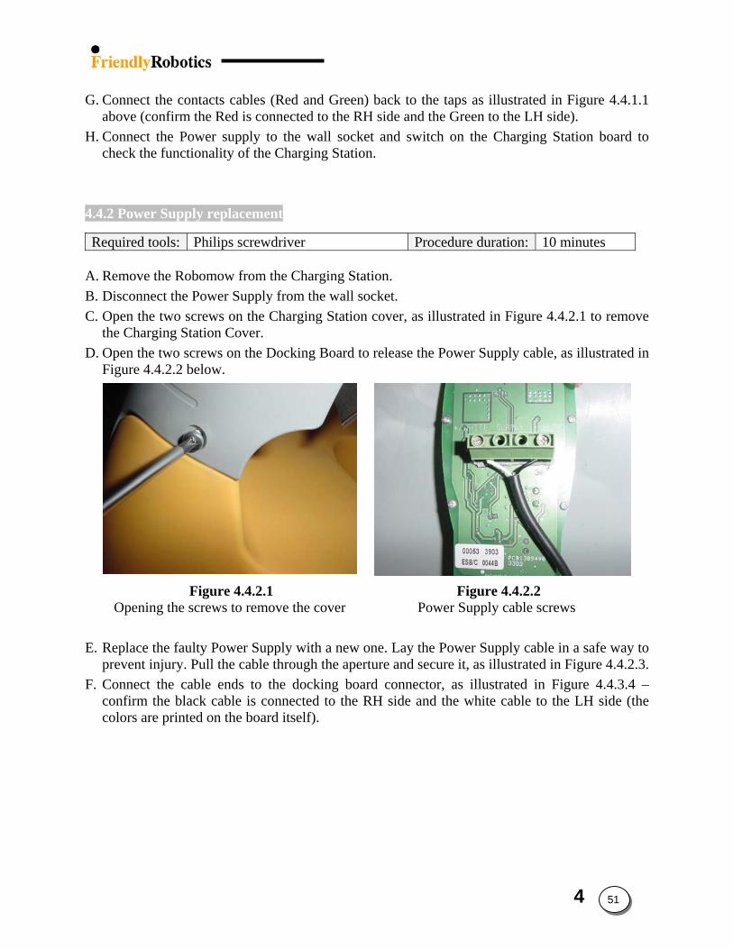
G. Connect the contacts cables (Red and Green) back to the taps as illustrated in Figure 4.4.1.1
above (confirm the Red is connected to the RH side and the Green to the LH side). H. Connect the Power supply to the wall socket and switch on the Charging Station board to
check the functionality of the Charging Station.
4.4.2 Power Supply replacement
Required tools: Philips screwdriver Procedure duration: 10 minutes
A. Remove the Robomow from the Charging Station. B. Disconnect the Power Supply from the wall socket. C. Open the two screws on the Charging Station cover, as illustrated in Figure 4.4.2.1 to remove
the Charging Station Cover. D. Open the two screws on the Docking Board to release the Power Supply cable, as illustrated in
Figure 4.4.2.2 below.
Figure 4.4.2.1 Figure 4.4.2.2 Opening the screws to remove the cover Power Supply cable screws E. Replace the faulty Power Supply with a new one. Lay the Power Supply cable in a safe way to
prevent injury. Pull the cable through the aperture and secure it, as illustrated in Figure 4.4.2.3. F. Connect the cable ends to the docking board connector, as illustrated in Figure 4.4.3.4 –
confirm the black cable is connected to the RH side and the white cable to the LH side (the colors are printed on the board itself).
4 51
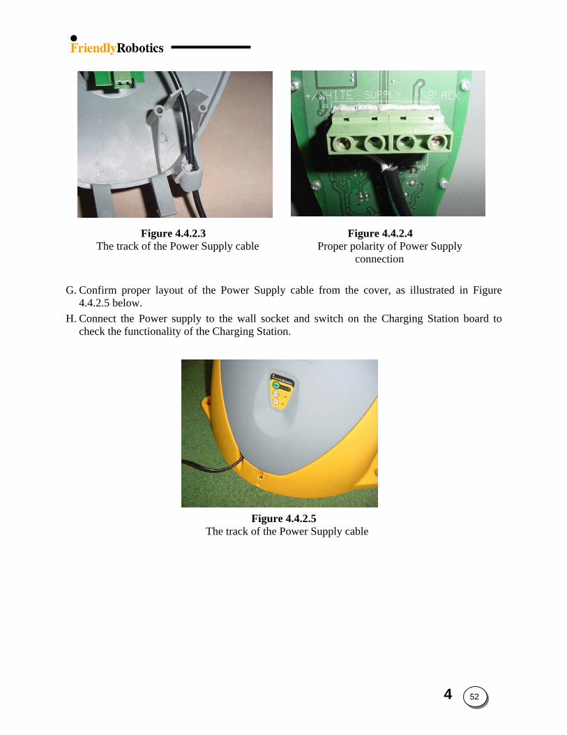
Figure 4.4.2.3 Figure 4.4.2.4 The track of the Power Supply cable Proper polarity of Power Supply
connection G. Confirm proper layout of the Power Supply cable from the cover, as illustrated in Figure
4.4.2.5 below. H. Connect the Power supply to the wall socket and switch on the Charging Station board to
check the functionality of the Charging Station.
Figure 4.4.2.5 The track of the Power Supply cable
4 52
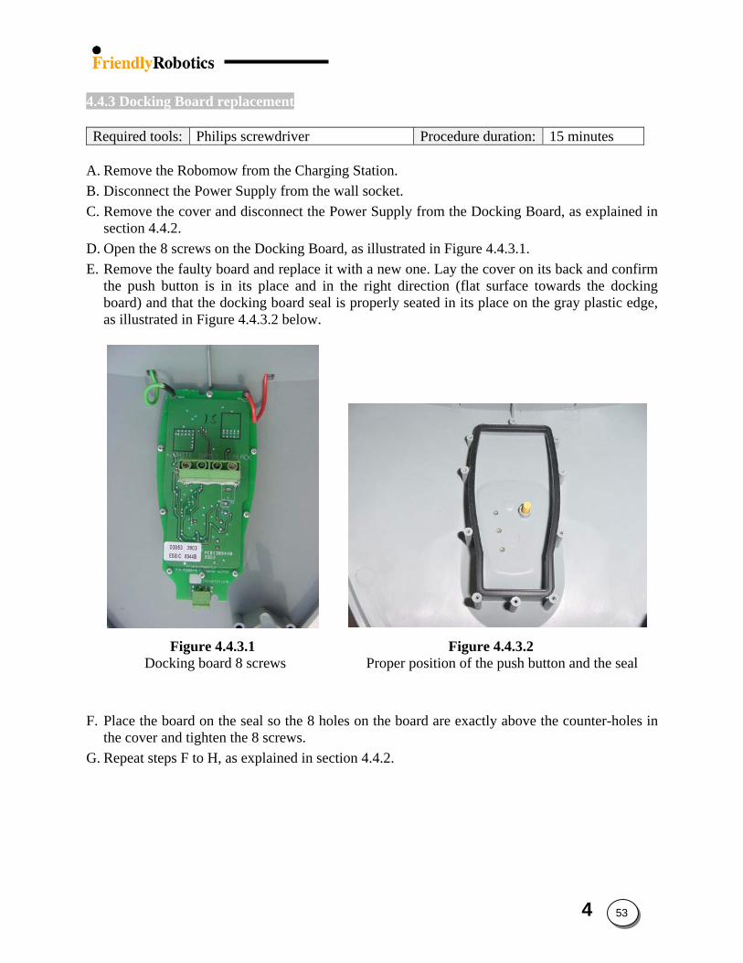
4.4.3 Docking Board replacement
Required tools: Philips screwdriver Procedure duration: 15 minutes
A. Remove the Robomow from the Charging Station. B. Disconnect the Power Supply from the wall socket. C. Remove the cover and disconnect the Power Supply from the Docking Board, as explained in
section 4.4.2. D. Open the 8 screws on the Docking Board, as illustrated in Figure 4.4.3.1. E. Remove the faulty board and replace it with a new one. Lay the cover on its back and confirm
the push button is in its place and in the right direction (flat surface towards the docking board) and that the docking board seal is properly seated in its place on the gray plastic edge, as illustrated in Figure 4.4.3.2 below.
Figure 4.4.3.1 Figure 4.4.3.2 Docking board 8 screws Proper position of the push button and the seal
F. Place the board on the seal so the 8 holes on the board are exactly above the counter-holes in the cover and tighten the 8 screws.
G. Repeat steps F to H, as explained in section 4.4.2.
4 53
5. Diagnostics
The Diagnostics section of the Service Guide refers directly to the ‘Service’ menu accessed on the Robomow Manual controller. The Robomow has a series of self-diagnostic tests that allow it to pinpoint problems or test systems affecting the operation. By entering the ‘Service’ menu and selecting the specific system or component test, the Robomow will display either a ‘Pass’ or ‘Fail’ message or display a fault code, which is referenced in Section 5.6 to determine the nature of the problem.
This section closely cross-references with Section 3, Troubleshooting. In Section 3, many
of the troubleshooting flow charts request a specific diagnostic test to be performed. The results of each of these diagnostic tests are then used to determine the system or component of failure. This section outlines the procedure for performing these tests as well as an interpretation of the results, found in the Fault Code Tables, Section 5.6.
5. Diagnostics - Contents
5.1 General test ………………………………………………..5.2 5.2 Service key procedure……………………………………..5.3 5.3 Calibration procedures………………………………...…..5.5 5.4 Testing procedures……………………………………...…5.8 5.5 Settings procedures………………………………………..5.15 5.6 Diagnostics fault codes……………………………………5.24 5.7 Last Stop Cause………………………………………...…5.28
5 1
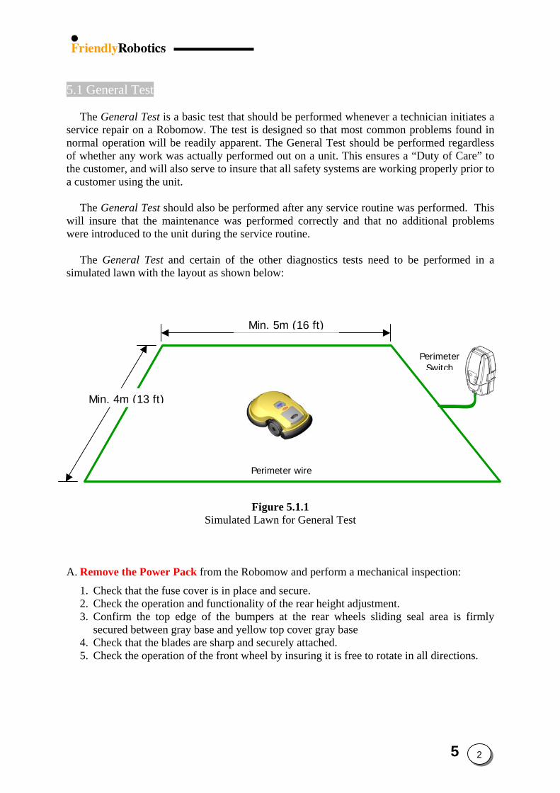
5.1 General Test The General Test is a basic test that should be performed whenever a technician initiates a
service repair on a Robomow. The test is designed so that most common problems found in normal operation will be readily apparent. The General Test should be performed regardless of whether any work was actually performed out on a unit. This ensures a “Duty of Care” to the customer, and will also serve to insure that all safety systems are working properly prior to a customer using the unit.
The General Test should also be performed after any service routine was performed. This
will insure that the maintenance was performed correctly and that no additional problems were introduced to the unit during the service routine.
The General Test and certain of the other diagnostics tests need to be performed in a
simulated lawn with the layout as shown below:
Min. 4m (13 ft)
Min. 5m (16 ft)
Perimeter Switch
Perimeter wire
Figure 5.1.1
Simulated Lawn for General Test
A. Remove the Power Pack from the Robomow and perform a mechanical inspection:
1. Check that the fuse cover is in place and secure. 2. Check the operation and functionality of the rear height adjustment. 3. Confirm the top edge of the bumpers at the rear wheels sliding seal area is firmly
secured between gray base and yellow top cover gray base 4. Check that the blades are sharp and securely attached. 5. Check the operation of the front wheel by insuring it is free to rotate in all directions.
5 2
B. Clean the unit using compressed air; particularly inside the Power Pack well and Manual
controller well drain holes. A damp cloth and a wooden stick can also be used to remove stubborn dirt and debris. Do not wash with a hose.
C. Insert the Power Pack and perform the following tests:
1. Check that the operating lamp illuminates when the Power Pack is inserted. 2. Check that the Manual controller display is working properly. Inspect the controller for
signs of damage to the housing, cable, buttons or display. 3. Slightly lift the front of the unit by the carrying handle and insure that the unit
announces the front wheel lifted audio alert. 4. Confirm that the bumpers are functioning correctly by using the ‘Bumper tests’ under
the ‘Safety tests’ menu. Hit the top of the mower hard with your hand and make sure the bumper sound is not heard.
5. Confirm that the Manual controller buttons are functioning correctly by using the ‘Buttons test’ under the ‘Safety tests’ menu.
6. Check charging
SAFETY FIRST! Before completing the following tests, insure that thetest area is clear of persons and obstacles. Remove all floor debris toprevent it from being thrown by the rotating blades. Keep feet and handsaway from the blades and the drive wheels when testing.
D. Drive the Robomow manually forwards, backwards, left and right and perform the ‘Drive motor test’ under the ‘Service’ menu (See section 5.4.4).
E. Manually activate the mowing motors and perform the ‘Mowing test’ under the ‘Service’
menu (See section 5.4.5). F. Operate the Robomow automatically in the simulated lawn. Verify it follow the perimeter
wire in edge mode and move in a straight lines when it moves inside the area in Scan mode.
5.2 Service Key
The Service Key is a function in the Robomow software that allows a service technician
to access diagnostics and service functions. These menu functions are not available to the end user.
In order to access the Service Key, select the ‘Service’ menu item under the ‘User
options’ menu and press the ‘GO’ button. Use the arrow buttons to scroll through the numbers. Use the ‘GO’ button to acknowledge each number and move to the next digit. Use the ‘C’ button to cancel a selection and move back in the sequence.
Use this process to select the number 12321. This is the required code to enter the
‘Service’ function menus.
5 3

(RL500: On Manual/settings press green button, scroll up to Service key, insert 12321,
green button, Confirm, green button and the menu will jump to Diagnostics. Green button to get into diagnostic mode and now scroll down or up to the wanted test).
Calibration, Tests and Settings
Various calibrations, tests and settings are found under the ‘Service’ menu that may be
used by the technician. Each of these tests is selectable by simply scrolling through the menu. After completing work in a specific area, perform the test shown in the procedure and then perform the General Test outlined in Section 5.1. This will insure that the repair has been done properly and that the unit functions satisfactorily.
The results of some tests will be a pass or fail while others will display a fault code
number. Refer to the fault code in Section 5.6 Diagnostics Fault Codes. Please follow the instructions for each test carefully. At the end of each test press the ‘C’
button to exit. Continual pressing of the ‘C’ button will move you up through the menu levels, until you arrive at the Main Menu.
Too busy, lack of time or do not understand the test fully: At least operate the Robomow
on the test area in automatic mode, to make sure it is fully operational. Testing it in manual mode for driving or manual mowing is not satisfactory at all prior to handing it back to the customer. The Robomow has built in warning and indication system that will pop up on the display in Automatic mode in case you forgot to perform any of the needed calibrations after service.
5 4
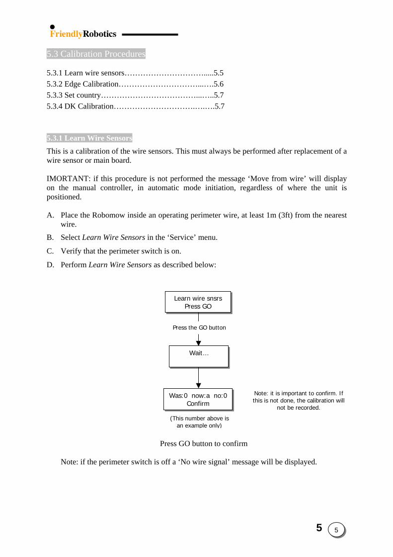
5.3 Calibration Procedures
5.3.1 Learn wire sensors………………………….....5.5 5.3.2 Edge Calibration…………………………...….5.6 5.3.3 Set country………………………………...…..5.7 5.3.4 DK Calibration………………………….….….5.7
5.3.1 Learn Wire Sensors This is a calibration of the wire sensors. This must always be performed after replacement of a wire sensor or main board. IMORTANT: if this procedure is not performed the message ‘Move from wire’ will display on the manual controller, in automatic mode initiation, regardless of where the unit is positioned. A. Place the Robomow inside an operating perimeter wire, at least 1m (3ft) from the nearest
wire.
B. Select Learn Wire Sensors in the ‘Service’ menu.
C. Verify that the perimeter switch is on.
D. Perform Learn Wire Sensors as described below:
Pre
Note: if the perimeter switch is off
Learn wire snsrsPress GO
Note: it is important to confirm. If this is not done, the calibration will
not be recorded.
Press the GO button
Wait…
Confirm
(This number above is
Was:0 now:a no:0
ss GO button to confirm
a ‘No wire signal’ message will be displayed.
an example only)
5 5
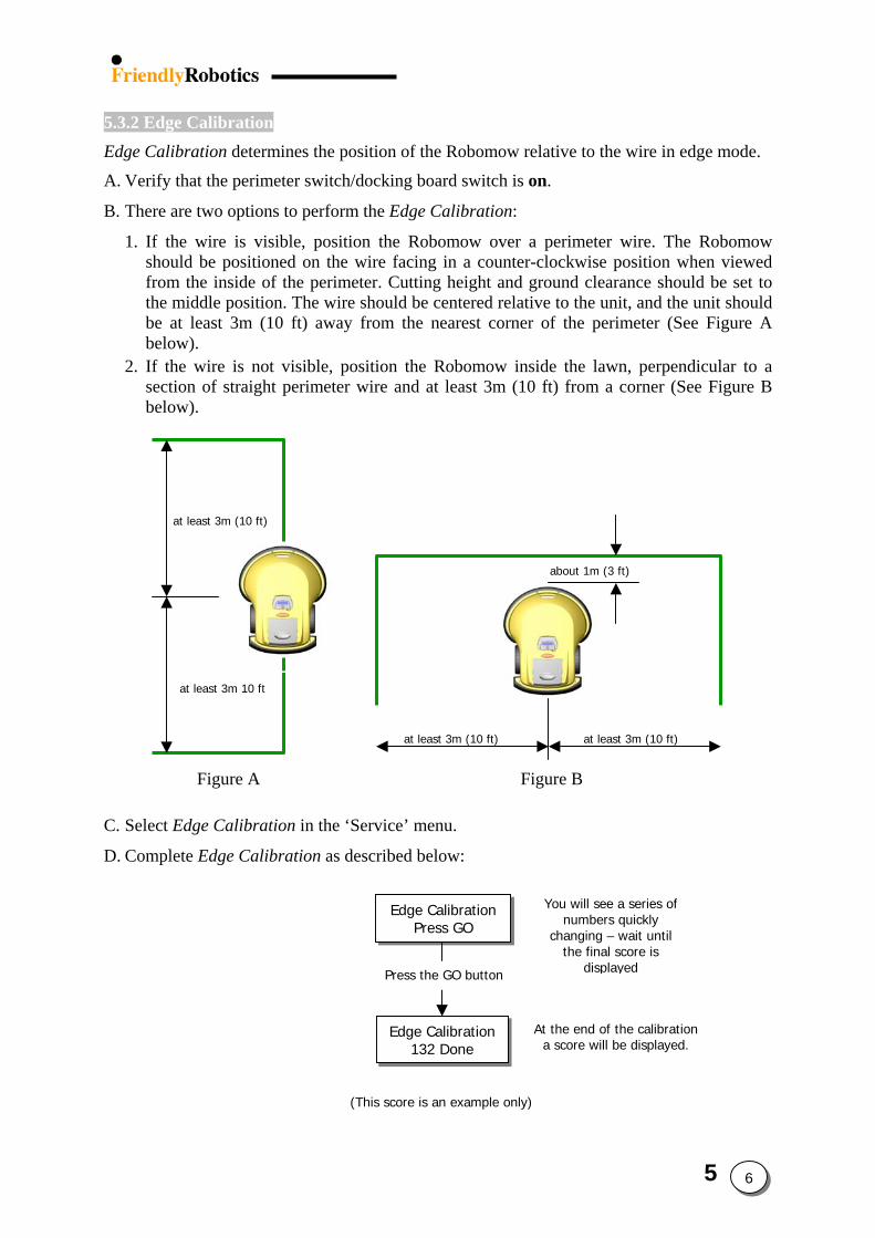
5.3.2 Edge Calibration Edge Calibration determines the position of the Robomow relative to the wire in edge mode.
A. Verify that the perimeter switch/docking board switch is on.
B. There are two options to perform the Edge Calibration:
1. If the wire is visible, position the Robomow over a perimeter wire. The Robomow should be positioned on the wire facing in a counter-clockwise position when viewed from the inside of the perimeter. Cutting height and ground clearance should be set to the middle position. The wire should be centered relative to the unit, and the unit should be at least 3m (10 ft) away from the nearest corner of the perimeter (See Figure A below).
2. If the wire is not visible, position the Robomow inside the lawn, perpendicular to a section of straight perimeter wire and at least 3m (10 ft) from a corner (See Figure B below).
Figure A Figure B
about 1m (3 ft)
at least 3m (10 ft)
at least 3m (10 ft)
at least 3m 10 ft
at least 3m (10 ft)
C. Select Edge Calibration in the ‘Service’ menu.
D. Complete Edge Calibration as described below:
Press the GO button
Edge Calibration132 Done
Edge CalibrationPress GO
A
(This score is an example only)
You will see a series of numbers quickly
changing – wait until
the final score isdisplayed
t the end of the calibration
a score will be displayed.5 6
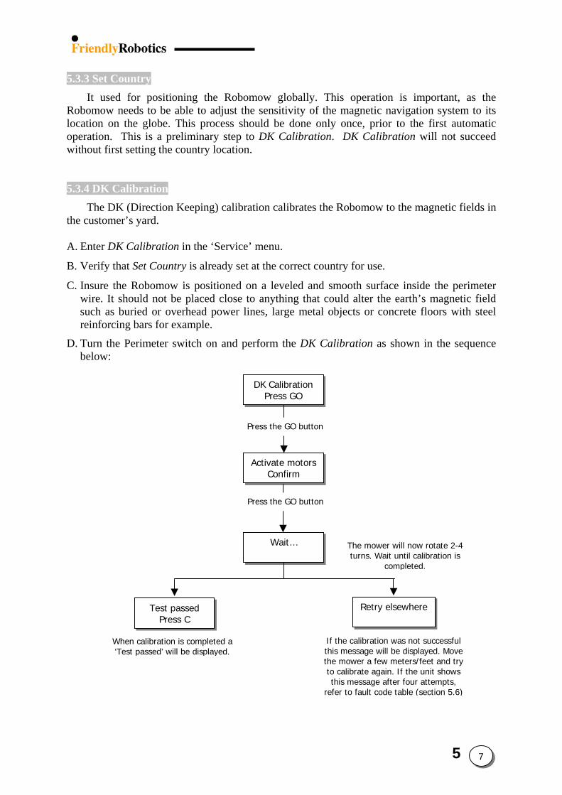
5.3.3 Set Country
It used for positioning the Robomow globally. This operation is important, as the Robomow needs to be able to adjust the sensitivity of the magnetic navigation system to its location on the globe. This process should be done only once, prior to the first automatic operation. This is a preliminary step to DK Calibration. DK Calibration will not succeed without first setting the country location.
5.3.4 DK Calibration The DK (Direction Keeping) calibration calibrates the Robomow to the magnetic fields in
the customer’s yard.
A. Enter DK Calibration in the ‘Service’ menu.
B. Verify that Set Country is already set at the correct country for use.
C. Insure the Robomow is positioned on a leveled and smooth surface inside the perimeter wire. It should not be placed close to anything that could alter the earth’s magnetic field such as buried or overhead power lines, large metal objects or concrete floors with steel reinforcing bars for example.
D. Turn the Perimeter switch on and perform the DK Calibration as shown in the sequence below:
P
P
Test passed
When calibration is completed a ‘Test passed’ will be displayed.
ress the GO button
DK CalibrationPress GO
Wait…
ress the GO button
Activate motorsConfirm
thisrefer
The mower will now rotate 2-4
turns. Wait until calibration is completed.
Retry elsewhere
Press CIf the calibration was not successful this message will be displayed. Move the mower a few meters/feet and try to calibrate again. If the unit shows
message after four attempts, to fault code table (section 5.6)
5 7

5.4 Tests Procedures 5.4.1 Wire sensors…………………………..…..5.9 5.4.2 Rain Sensor……………………….………5.10 5.4.3 Direction keeper…………………….….…5.10 5.4.4 Drive motors…………………………..….5.11 5.4.5 Mowing motors…………………...…...…5.11 5.4.6 Thermistors………………………….…....5.12 5.4.7 Docking……………………………..……5.12 5.4.8 Edge………………………….……......….5.13 5.4.9 Bat. Maintenance………………....…....…5.14
5 8
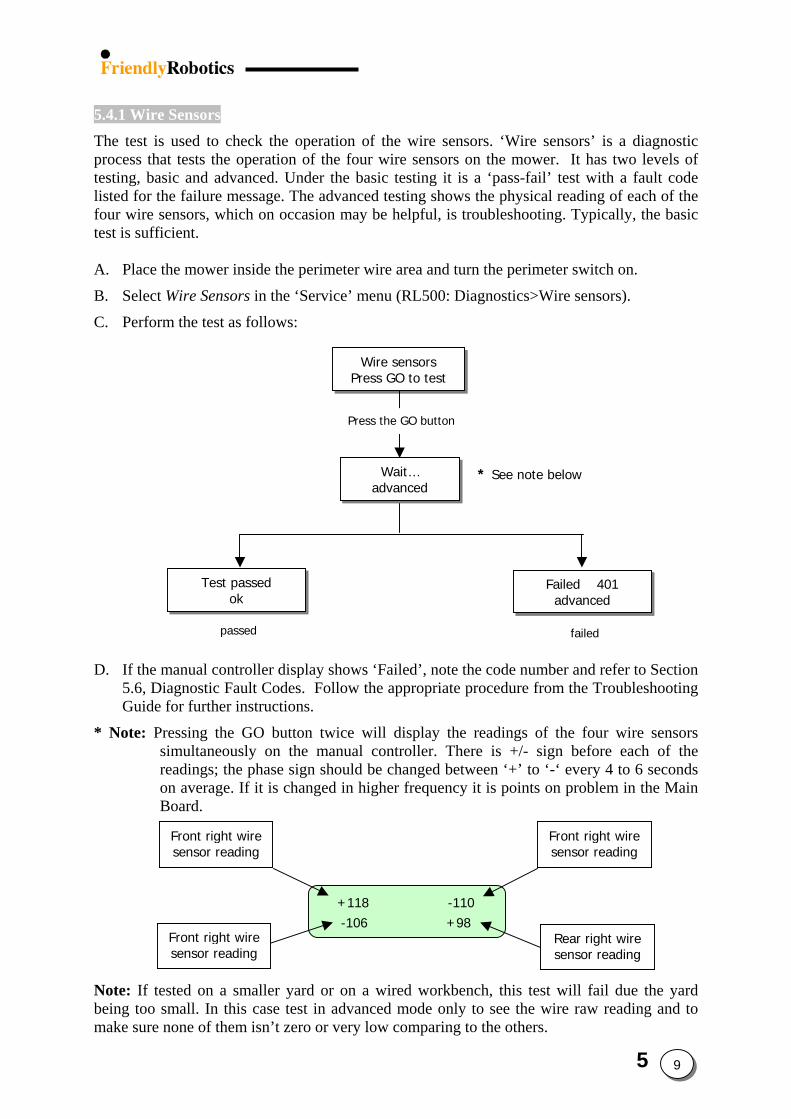
5.4.1 Wire Sensors The test is used to check the operation of the wire sensors. ‘Wire sensors’ is a diagnostic process that tests the operation of the four wire sensors on the mower. It has two levels of testing, basic and advanced. Under the basic testing it is a ‘pass-fail’ test with a fault code listed for the failure message. The advanced testing shows the physical reading of each of the four wire sensors, which on occasion may be helpful, is troubleshooting. Typically, the basic test is sufficient. A. Place the mower inside the perimeter wire area and turn the perimeter switch on.
B. Select Wire Sensors in the ‘Service’ menu (RL500: Diagnostics>Wire sensors).
C. Perform the test as follows:
Press the GO button
a
P t
w
D. If the manu5.6, DiagnoGuide for f
* Note: Pressinsimulreadinon avBoard
Fronsen
Fronsens
Note: If tested being too smallmake sure none
Test passed
passed
ok
al controller display shows ‘stic Fault Codes. Follow th
urther instructions.
g the GO button twice wtaneously on the manual cgs; the phase sign should b
erage. If it is changed in hig.
+118 -106
t right wire sor reading
t right wire or reading
on a smaller yard or on a . In this case test in advanc of them isn’t zero or very lo
Wait… dvanced
Wire sensors ress GO to tes
Failed’, note the code nume appropriate procedure fr
ill display the readings oontroller. There is +/- se changed between ‘+’ toher frequency it is points
-110 +98
wired workbench, this teed mode only to see the w comparing to the others
Failed 401
* See note belo
advanced
failed
ber and refer to Section om the Troubleshooting
f the four wire sensors ign before each of the ‘-‘ every 4 to 6 seconds on problem in the Main
Front right wire sensor reading
Rear right wire sensor reading
st will fail due the yard wire raw reading and to .
5 9
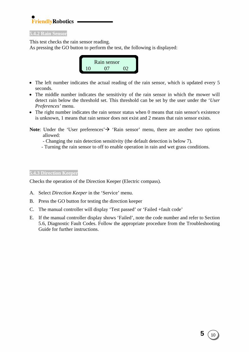
5.4.2 Rain Sensor This test checks the rain sensor reading. As pressing the GO button to perform the test, the following is displayed:
Rain sensor10 07 02
Rain sensor10 07 02
• The left number indicates the actual reading of the rain sensor, which is updated every 5
seconds. • The middle number indicates the sensitivity of the rain sensor in which the mower will
detect rain below the threshold set. This threshold can be set by the user under the ‘User Preferences’ menu.
• The right number indicates the rain sensor status when 0 means that rain sensor's existence is unknown, 1 means that rain sensor does not exist and 2 means that rain sensor exists.
Note: Under the ‘User preferences’ ‘Rain sensor’ menu, there are another two options
allowed: - Changing the rain detection sensitivity (the default detection is below 7).
- Turning the rain sensor to off to enable operation in rain and wet grass conditions.
5.4.3 Direction Keeper Checks the operation of the Direction Keeper (Electric compass). A. Select Direction Keeper in the ‘Service’ menu.
B. Press the GO button for testing the direction keeper
C. The manual controller will display ‘Test passed’ or ‘Failed +fault code’
E. If the manual controller display shows ‘Failed’, note the code number and refer to Section 5.6, Diagnostic Fault Codes. Follow the appropriate procedure from the Troubleshooting Guide for further instructions.
5 10
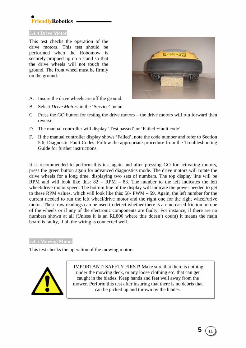
5.4.4 Drive Motor This test checks the operation of the drive motors. This test should be performed when the Robomow is securely propped up on a stand so that the drive wheels will not touch the ground. The front wheel must be firmly on the ground. A. Insure the drive wheels are off the ground.
B. Select Drive Motors in the ‘Service’ menu.
C. Press the GO button for testing the drive motors – the drive motors will run forward then reverse.
D. The manual controller will display ‘Test passed’ or ‘Failed +fault code’
F. If the manual controller display shows ‘Failed’, note the code number and refer to Section 5.6, Diagnostic Fault Codes. Follow the appropriate procedure from the Troubleshooting Guide for further instructions.
It is recommended to perform this test again and after pressing GO for activating motors, press the green button again for advanced diagnostics mode. The drive motors will rotate the drive wheels for a long time, displaying two sets of numbers. The top display line will be RPM and will look like this: 82 – RPM – 83. The number to the left indicates the left wheel/drive motor speed. The bottom line of the display will indicate the power needed to get to these RPM values, which will look like this: 58- PWM – 59. Again, the left number for the current needed to run the left wheel/drive motor and the right one for the right wheel/drive motor. These raw readings can be used to detect whether there is an increased friction on one of the wheels or if any of the electronic components are faulty. For instance, if there are no numbers shown at all (Unless it is an RL800 where this doesn’t count) it means the main board is faulty, if all the wiring is connected well.
5.4.5 Mowing Motor This test checks the operation of the mowing motors.
IMPORTANT: SAFETY FIRST! Make sure that there is nothing under the mowing deck, or any loose clothing etc. that can get caught in the blades. Keep hands and feet well away from the
mower. Perform this test after insuring that there is no debris that can be picked up and thrown by the blades.
5 11
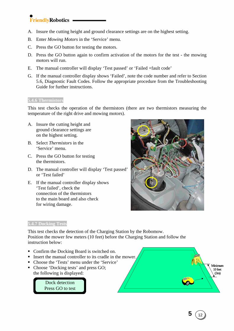
A. Insure the cutting height and ground clearance settings are on the highest setting.
B. Enter Mowing Motors in the ‘Service’ menu.
C. Press the GO button for testing the motors.
D. Press the GO button again to confirm activation of the motors for the test - the mowing motors will run.
E. The manual controller will display ‘Test passed’ or ‘Failed +fault code’
G. If the manual controller display shows ‘Failed’, note the code number and refer to Section 5.6, Diagnostic Fault Codes. Follow the appropriate procedure from the Troubleshooting Guide for further instructions.
5.4.6 Thermistors This test checks the operation of the thermistors (there are two thermistors measuring the temperature of the right drive and mowing motors). A. Insure the cutting height and
ground clearance settings are on the highest setting.
B. Select Thermistors in the ‘Service’ menu.
C. Press the GO button for testing the thermistors.
D. The manual controller will display ‘Test passed’ or ‘Test failed’
E. If the manual controller display shows ‘Test failed’, check the connection of the thermistors to the main board and also check for wiring damage.
5.4.7 Docking Tests This test checks the detection of the Charging Station by the Robomow. Position the mower few meters (10 feet) before the Charging Station and follow the instruction below:
Minimum 10 feet (3m)
Minimum 10 feet (3m)
Confirm the Docking Board is switched on. Insert the manual controller to its cradle in the mower. Choose the ‘Tests’ menu under the ‘Service’
Dock detectionPress GO to testDock detectionPress GO to test
Choose ‘Docking tests’ and press GO; the following is displayed:
5 12
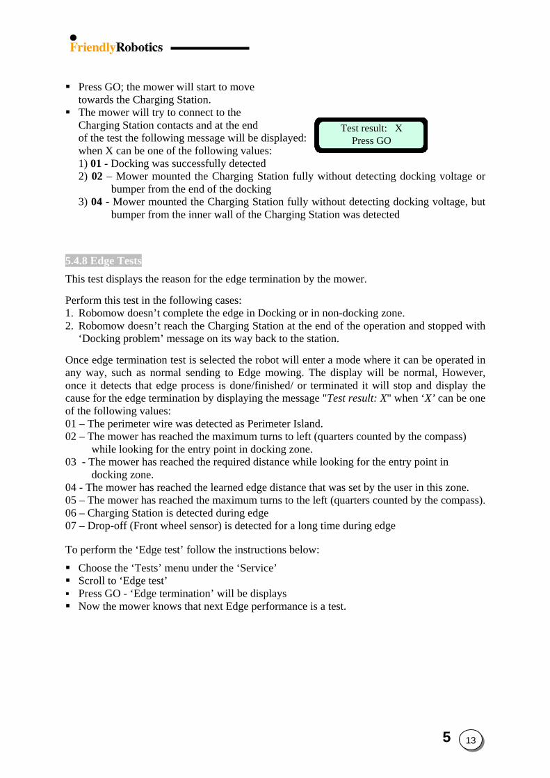
Press GO; the mower will start to move
towards the Charging Station.
Test result: XPress GO
Test result: XPress GO
The mower will try to connect to the Charging Station contacts and at the end of the test the following message will be displayed: when X can be one of the following values: 1) 01 - Docking was successfully detected 2) 02 – Mower mounted the Charging Station fully without detecting docking voltage or
bumper from the end of the docking 3) 04 - Mower mounted the Charging Station fully without detecting docking voltage, but
bumper from the inner wall of the Charging Station was detected 5.4.8 Edge Tests This test displays the reason for the edge termination by the mower. Perform this test in the following cases: 1. Robomow doesn’t complete the edge in Docking or in non-docking zone. 2. Robomow doesn’t reach the Charging Station at the end of the operation and stopped with
‘Docking problem’ message on its way back to the station. Once edge termination test is selected the robot will enter a mode where it can be operated in any way, such as normal sending to Edge mowing. The display will be normal, However, once it detects that edge process is done/finished/ or terminated it will stop and display the cause for the edge termination by displaying the message "Test result: X" when ‘X’ can be one of the following values: 01 – The perimeter wire was detected as Perimeter Island. 02 – The mower has reached the maximum turns to left (quarters counted by the compass)
while looking for the entry point in docking zone. 03 - The mower has reached the required distance while looking for the entry point in
docking zone. 04 - The mower has reached the learned edge distance that was set by the user in this zone. 05 – The mower has reached the maximum turns to the left (quarters counted by the compass). 06 – Charging Station is detected during edge 07 – Drop-off (Front wheel sensor) is detected for a long time during edge To perform the ‘Edge test’ follow the instructions below:
Choose the ‘Tests’ menu under the ‘Service’ Scroll to ‘Edge test’ Press GO - ‘Edge termination’ will be displays Now the mower knows that next Edge performance is a test.
5 13
5.4.9 Bat. Maintenance Battery Maintenance is a multiple menu selection. It can provide valuable information on the charging maintenance habits of the customer as well as to help in identifying a faulty power pack. Last Battery Voltage – this selection will tell you the last measured voltage of the power pack. This number is updated frequently when in charging mode and in automatic operation mode. If the mower is allowed to enter deep sleep mode, the last recorded voltage prior to deep sleep will be recorded here. This can be useful in determining charger operation by viewing the voltage over time. Additionally, it can be used to view voltage over time while in operation to understand a discharge rate to determine power pack condition. Warning Ignored – the energy management system of the mower will issue audible and text messaging alerts to the user to prompt them to connect the mower to the charger when not in use (if the customer has failed to do so). The warnings vary in frequency of time and loudness, depending on the time disconnected from the charger. This warning system will function for approximately 48 hours before shutting down and entering a deep sleep mode for energy conservation. This selection indicates how many times the customer has ignored the alert system and allowed the mower to enter the deep sleep mode. This can indicate poor maintenance by the customer and could cause diminished power pack performance and service life. While any number here is cause for concern and illustrates the need to educate the user on proper maintenance, a count of more than 2 or more is serious and can damage the power pack. Poor Storage – poor storage counter indicates how many times the mower was put into operation where the power pack capacity was less than 80% of fully charged. This essentially indicates how often the mower was used prior to the power pack being fully charged, where the count will not start until there is a 20% capacity loss from fully charged. The 20% criteria is important, as many people will use the mower is several smaller areas in addition to one large area. A smaller area will discharge the power pack, but not to the 20% level, so we do not want to count these types of operations. A high count here, greater than 3 or 4 indicates the user is not allowing enough time for the power pack to fully charge. If they indicate they must do this in order to mow all of their lawn (unclear), it is suggested they purchase an additional power pack and external charger. Lastly, if the voltage of a power pack when inserted is less than 90% of the last measured voltage, it indicates the user is not fully charging the power pack prior to off-season storage, which is critical for good service life. Reset – allows for resetting of all the listed battery parameters back to zero when a new power pack has been put in service or possibly if a service repair was done which may have affected the counters.
5 14
5.5 Settings Procedures 5.5.1 Docking Options……………..……...……5.16
5.5.1.1 Edge to dock……………….5.16 5.5.1.2 Docking search vlt. ………..5.16 5.5.1.3 Dock bumper………………5.16 5.5.1.4 Island……….……….….….5.16
5.5.2 Small wheels……………………….…......5.16 5.5.3 Enable DK. ………………..……….…….5.16 5.5.4 Max leg distance…………………….……5.17 5.5.5 Thermistors.………………..……....….….5.17 5.5.6 Mowing…………………………....…...…5.17 5.5.7 Drv. overcurrent………………….….……5.17 5.5.8 Mow overcurrent…………………….……5.17 5.5.9 Auto restart………………………….…….5.18
5.5.9.1 Drive overload…………….5.18 5.5.9.2 Mow overload. ………..…..5.18 5.5.9.3 Power break…………….…5.18
5.5.10. Special display…………………….…….5.18 5.5.10.1 Charging………………….5.18 5.5.10.2 Wire sensors. ………...…..5.20 5.5.10.3 Temperatures…………..…5.20 5.5.10.4 Edge…………………...….5.21 5.5.10.5 Drive motors. ……...……..5.22 5.5.10.6 Mow motors………………5.22
5.5.11 Factory Defaults…………...………….…5.23
5 15
5.5.1 Docking Options General comment: There is no need to change the settings under the ‘Docking Options’, unless there is an exception case, which prevent the mower to works normally. These options appeared in the menu as a backup only.
5.5.1.1 Edge to Dock The ‘Edge to dock’ enable the mower to complete the edge operation from the Charging Station back to the Charging Station without any condition, otherwise there are few events that may cause the mower to leave the edge, such as distance limit or number of turns to the right or to the left. If the mower doesn’t complete the edge in ‘Dock zone’, first perform ‘Edge termination test’ (refer to section 5.4.8) and based on the test result, decide about the next step to be done.
5.5.1.2 Docking search vlt. Option to increase the ‘Searching dock’ threshold voltage to 22.5 or 23.0 (the default is 22.0) in case, which the mower doesn't succeed to drive back to the Charging Station because of low battery voltage.
5.5.1.3 Dock bumper Changing this option to 'off' will change the bumper behavior so it will make bypass in every bumper event during 'Edge' mode and will not push against obstacle. Note: Setting this option to ‘off’ may prevent the mower to enter the Charging Station in case, which bumper is detected as the mower enter to the Charging Station.
5.5.1.4 Islands Setting this option to ‘off’ allow the mower to acquire the Perimeter Wire immediately as starting to search for the Charging Station with no need to converge to the end of the lawn.
5.5.2 Small Wheels It is an option to set the size of the drive wheels being used on the Robomow. The default settings are: - RL350/550: Small wheels set to ‘on’. - RL850/1000: Small wheels set to ‘off’ This setting is used when changing the drive wheel size on the Robomow. If this setting is not correct for the wheel size, the mower will not navigate properly and will likely not drive in straight lines.
5.5.3 Enable DK Enable DK is a feature that is helpful when operating the mower in an area where magnetic interference is suspected in a certain lawn or when the Robomow is operated indoors, i.e. at an exhibition. Indoors exhibitions are typically on concrete floors that contain a great deal of metals. This large amount of metal will skew the magnetic field causing the mower to run in curved lines rather than straight lines. Turning the ‘Enable DK’ feature off will allow the mower to navigate solely on wheel rotation measurement, thereby not using the magnetic field of the earth. This will allow for straight lines in a show environment. The default of this feature is always on.
5 16
Enable DK is divided into 2 modes: ‘edge’ and ‘scan’ and it is possible to disable the DK either in edge or scan. Disabling the DK in the 2 modes enables to operate the mower without compass at all (or when the compass is faulty). 5.5.4 Max leg distance Enable to set the max distance between the perimeter wires in every zone. There is a monitoring system that detects the wire sensors readings during operation. If the readings are not changed for some time (it depends on the distance between the wires), it means that the mower is probably stuck in place. For example: in lawn 10 by 30, the mower will not drive more than 10 meters with the same readings, but in lawn 40 by 90 it may drive for 60 meters with no changes in the wire sensors readings. If during scanning it is found that the max leg distance set by the user is shorter than what does the mower calculate, then the S.W will update it. 5.5.5 Thermistors (Enable) Enable Thermistors is set to ‘on’ as the factory default. This option is used when replacing a main board in an older model Robomow, which was manufactured without thermistors. Under this scenario, Thermistors must be turned to off or a failure message will display. However, the new board supports the use of thermistors, so the customer may elect to have the thermistors added to the unit at his expense, as an upgrade. 5.5.6 Mowing (Enable) The mowing feature provides the ability to disable the operation of the mowing motors. All other aspects of the mower will perform normally, however the blades will not rotate. This feature is useful when testing the set up of the perimeter wire prior to having the wire fully pegged to the ground, preventing the risk of cutting it. Additionally, it is a feature that can be used when using the mower in exhibitions, for safety reasons.
5.5.7 Drv. Over current (Drive Over current) This feature monitors the drive over current by the software. The default threshold is 50 (software units). If the mower detects over current (above 50) for 5 seconds continuously, the mower changes direction. This option enables setting the drive over current (load) threshold in which the mower will change the drive direction. 5.5.8 Mow Over current This feature monitors the mowing over current by the software. The default threshold is 10 (software units). If the mower detects over current (above 10) for 15 seconds continuously, the mower changes direction. This option enables setting the mow over current (load) threshold in which the mower will change direction to move from the area with high grass.
5 17
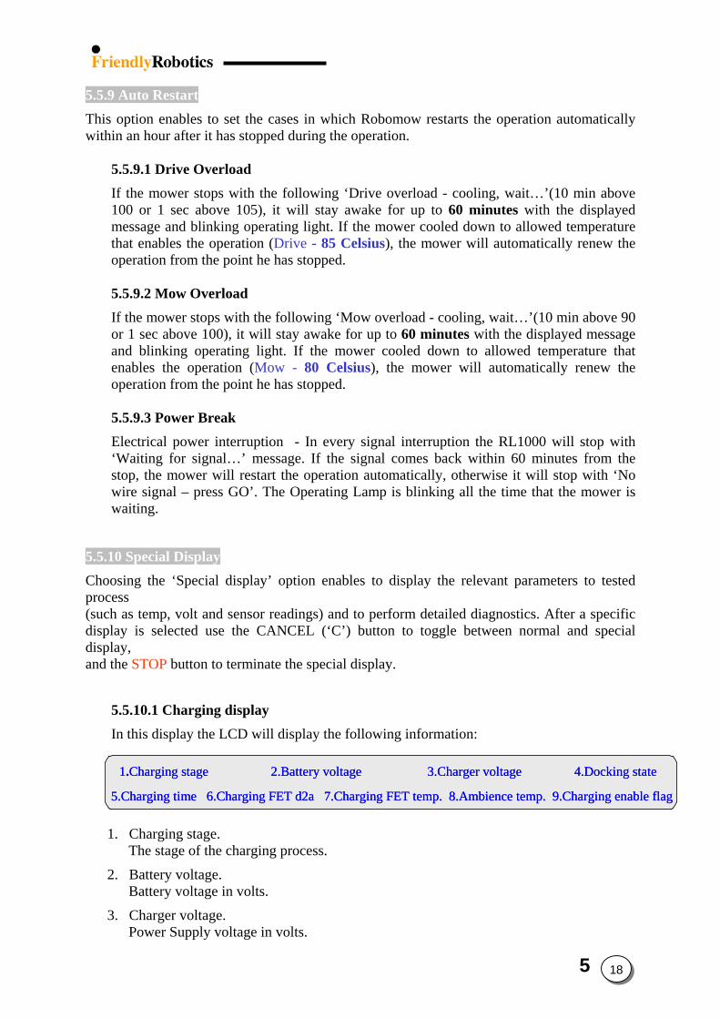
5.5.9 Auto Restart This option enables to set the cases in which Robomow restarts the operation automatically within an hour after it has stopped during the operation.
5.5.9.1 Drive Overload If the mower stops with the following ‘Drive overload - cooling, wait…’(10 min above 100 or 1 sec above 105), it will stay awake for up to 60 minutes with the displayed message and blinking operating light. If the mower cooled down to allowed temperature that enables the operation (Drive - 85 Celsius), the mower will automatically renew the operation from the point he has stopped.
5.5.9.2 Mow Overload If the mower stops with the following ‘Mow overload - cooling, wait…’(10 min above 90 or 1 sec above 100), it will stay awake for up to 60 minutes with the displayed message and blinking operating light. If the mower cooled down to allowed temperature that enables the operation (Mow - 80 Celsius), the mower will automatically renew the operation from the point he has stopped.
5.5.9.3 Power Break Electrical power interruption - In every signal interruption the RL1000 will stop with ‘Waiting for signal…’ message. If the signal comes back within 60 minutes from the stop, the mower will restart the operation automatically, otherwise it will stop with ‘No wire signal – press GO’. The Operating Lamp is blinking all the time that the mower is waiting.
5.5.10 Special Display Choosing the ‘Special display’ option enables to display the relevant parameters to tested process (such as temp, volt and sensor readings) and to perform detailed diagnostics. After a specific display is selected use the CANCEL (‘C’) button to toggle between normal and special display, and the STOP button to terminate the special display.
5.5.10.1 Charging display In this display the LCD will display the following information:
1.Charging stage 2.Battery voltage 3.Charger voltage 4.Docking state
5.Charging time 6.Charging FET d2a 7.Charging FET temp. 8.Ambience temp. 9.Charging enable flag
1.Charging stage 2.Battery voltage 3.Charger voltage 4.Docking state
5.Charging time 6.Charging FET d2a 7.Charging FET temp. 8.Ambience temp. 9.Charging enable flag
1.Charging stage 2.Battery voltage 3.Charger voltage 4.Docking state
5.Charging time 6.Charging FET d2a 7.Charging FET temp. 8.Ambience temp. 9.Charging enable flag
1. Charging stage.
The stage of the charging process.
2. Battery voltage. Battery voltage in volts.
3. Charger voltage. Power Supply voltage in volts.
5 18
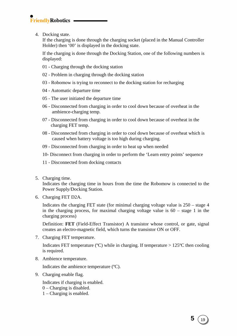
4. Docking state. If the charging is done through the charging socket (placed in the Manual Controller Holder) then ‘00’ is displayed in the docking state.
If the charging is done through the Docking Station, one of the following numbers is displayed:
01 - Charging through the docking station
02 - Problem in charging through the docking station
03 - Robomow is trying to reconnect to the docking station for recharging
04 - Automatic departure time
05 - The user initiated the departure time
06 - Disconnected from charging in order to cool down because of overheat in the ambience-charging temp.
07 - Disconnected from charging in order to cool down because of overheat in the charging FET temp.
08 - Disconnected from charging in order to cool down because of overheat which is caused when battery voltage is too high during charging.
09 - Disconnected from charging in order to heat up when needed
10- Disconnect from charging in order to perform the ‘Learn entry points’ sequence
11 - Disconnected from docking contacts
5. Charging time. Indicates the charging time in hours from the time the Robomow is connected to the Power Supply/Docking Station.
6. Charging FET D2A.
Indicates the charging FET state (for minimal charging voltage value is 250 – stage 4 in the charging process, for maximal charging voltage value is 60 – stage 1 in the charging process)
Definition: FET (Field-Effect Transistor) A transistor whose control, or gate, signal creates an electro-magnetic field, which turns the transistor ON or OFF.
7. Charging FET temperature.
Indicates FET temperature (ºC) while in charging. If temperature > 125ºC then cooling is required.
8. Ambience temperature.
Indicates the ambience temperature (ºC).
9. Charging enable flag.
Indicates if charging is enabled. 0 – Charging is disabled. 1 – Charging is enabled.
5 19
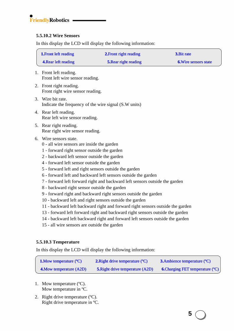
5 20
5.5.10.2 Wire Sensors In this display the LCD will display the following information:
1.Front left reading 2.Front right reading 3.Bit rate
4.Rear left reading 5.Rear right reading 6.Wire sensors state
1.Front left reading 2.Front right reading 3.Bit rate
4.Rear left reading 5.Rear right reading 6.Wire sensors state
1.Front left reading 2.Front right reading 3.Bit rate
4.Rear left reading 5.Rear right reading 6.Wire sensors state
1. Front left reading. Front left wire sensor reading.
2. Front right reading. Front right wire sensor reading.
3. Wire bit rate. Indicate the frequency of the wire signal (S.W units)
4. Rear left reading. Rear left wire sensor reading.
5. Rear right reading. Rear right wire sensor reading.
6. Wire sensors state. 0 - all wire sensors are inside the garden 1 - forward right sensor outside the garden 2 - backward left sensor outside the garden 4 - forward left sensor outside the garden 5 - forward left and right sensors outside the garden 6 - forward left and backward left sensors outside the garden 7 - forward left forward right and backward left sensors outside the garden 8 - backward right sensor outside the garden 9 - forward right and backward right sensors outside the garden 10 - backward left and right sensors outside the garden 11 - backward left backward right and forward right sensors outside the garden 13 - forward left forward right and backward right sensors outside the garden 14 - backward left backward right and forward left sensors outside the garden 15 - all wire sensors are outside the garden
5.5.10.3 Temperature In this display the LCD will display the following information:
1.Mow temperature (ºC) 2.Right drive temperature (ºC) 3.Ambience temperature (ºC)
4.Mow temperature (A2D) 5.Right drive temperature (A2D) 6.Charging FET temperature (ºC)
1.Mow temperature (ºC) 2.Right drive temperature (ºC) 3.Ambience temperature (ºC)
4.Mow temperature (A2D) 5.Right drive temperature (A2D) 6.Charging FET temperature (ºC)
1.Mow temperature (ºC) 2.Right drive temperature (ºC) 3.Ambience temperature (ºC)
4.Mow temperature (A2D) 5.Right drive temperature (A2D) 6.Charging FET temperature (ºC)
1. Mow temperature (ºC). Mow temperature in ºC.
2. Right drive temperature (ºC). Right drive temperature in ºC.
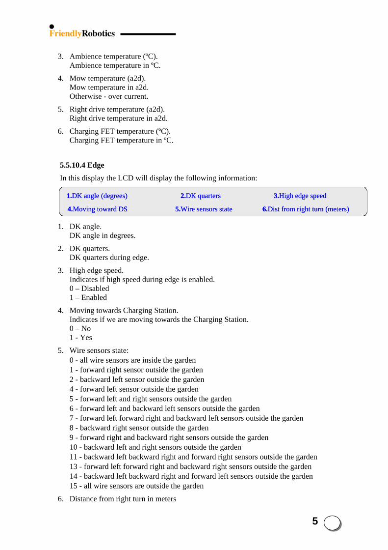
5 21
3. Ambience temperature (ºC). Ambience temperature in ºC.
4. Mow temperature (a2d). Mow temperature in a2d. Otherwise - over current.
5. Right drive temperature (a2d). Right drive temperature in a2d.
6. Charging FET temperature (ºC). Charging FET temperature in ºC.
5.5.10.4 Edge In this display the LCD will display the following information:
1.DK angle (degrees) 2.DK quarters 3.High edge speed
4.Moving toward DS 5.Wire sensors state 6.Dist from right turn (meters)
1.DK angle (degrees) 2.DK quarters 3.High edge speed
4.Moving toward DS 5.Wire sensors state 6.Dist from right turn (meters)
1.DK angle (degrees) 2.DK quarters 3.High edge speed
4.Moving toward DS 5.Wire sensors state 6.Dist from right turn (meters)
1. DK angle. DK angle in degrees.
2. DK quarters. DK quarters during edge.
3. High edge speed. Indicates if high speed during edge is enabled. 0 – Disabled 1 – Enabled
4. Moving towards Charging Station. Indicates if we are moving towards the Charging Station. 0 – No 1 - Yes
5. Wire sensors state: 0 - all wire sensors are inside the garden 1 - forward right sensor outside the garden 2 - backward left sensor outside the garden 4 - forward left sensor outside the garden 5 - forward left and right sensors outside the garden 6 - forward left and backward left sensors outside the garden 7 - forward left forward right and backward left sensors outside the garden 8 - backward right sensor outside the garden 9 - forward right and backward right sensors outside the garden 10 - backward left and right sensors outside the garden 11 - backward left backward right and forward right sensors outside the garden 13 - forward left forward right and backward right sensors outside the garden 14 - backward left backward right and forward left sensors outside the garden 15 - all wire sensors are outside the garden
6. Distance from right turn in meters
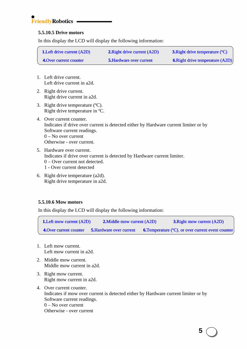
5 22
5.5.10.5 Drive motors In this display the LCD will display the following information:
1.Left drive current (A2D) 2.Right drive current (A2D) 3.Right drive temperature (ºC)
4.Over current counter 5.Hardware over current 6.Right drive temperature (A2D)
1.Left drive current (A2D) 2.Right drive current (A2D) 3.Right drive temperature (ºC)
4.Over current counter 5.Hardware over current 6.Right drive temperature (A2D)
1.Left drive current (A2D) 2.Right drive current (A2D) 3.Right drive temperature (ºC)
4.Over current counter 5.Hardware over current 6.Right drive temperature (A2D)
1. Left drive current. Left drive current in a2d.
2. Right drive current. Right drive current in a2d.
3. Right drive temperature (ºC). Right drive temperature in ºC.
4. Over current counter. Indicates if drive over current is detected either by Hardware current limiter or by Software current readings. 0 – No over current Otherwise - over current.
5. Hardware over current. Indicates if drive over current is detected by Hardware current limiter. 0 – Over current not detected. 1 - Over current detected
6. Right drive temperature (a2d). Right drive temperature in a2d.
5.5.10.6 Mow motors In this display the LCD will display the following information:
1.Left mow current (A2D) 2.Middle mow current (A2D) 3.Right mow current (A2D)
4.Over current counter 5.Hardware over current 6.Temperature (ºC). or over current event counter
1.Left mow current (A2D) 2.Middle mow current (A2D) 3.Right mow current (A2D)
4.Over current counter 5.Hardware over current 6.Temperature (ºC). or over current event counter
1.Left mow current (A2D) 2.Middle mow current (A2D) 3.Right mow current (A2D)
4.Over current counter 5.Hardware over current 6.Temperature (ºC). or over current event counter
1. Left mow current. Left mow current in a2d.
2. Middle mow current. Middle mow current in a2d.
3. Right mow current. Right mow current in a2d.
4. Over current counter. Indicates if mow over current is detected either by Hardware current limiter or by Software current readings. 0 – No over current Otherwise - over current
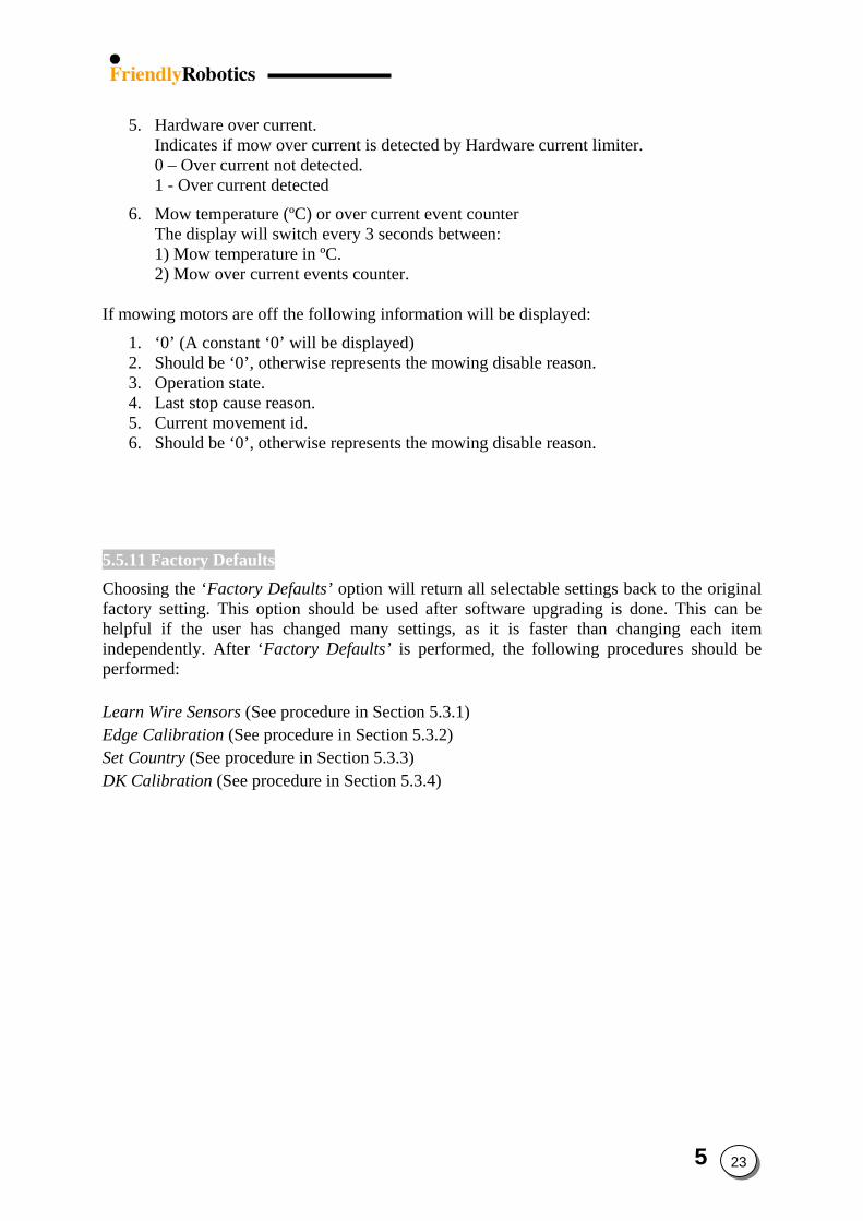
5. Hardware over current. Indicates if mow over current is detected by Hardware current limiter. 0 – Over current not detected. 1 - Over current detected
6. Mow temperature (ºC) or over current event counter The display will switch every 3 seconds between: 1) Mow temperature in ºC. 2) Mow over current events counter.
If mowing motors are off the following information will be displayed:
1. ‘0’ (A constant ‘0’ will be displayed) 2. Should be ‘0’, otherwise represents the mowing disable reason. 3. Operation state. 4. Last stop cause reason. 5. Current movement id. 6. Should be ‘0’, otherwise represents the mowing disable reason.
5.5.11 Factory Defaults Choosing the ‘Factory Defaults’ option will return all selectable settings back to the original factory setting. This option should be used after software upgrading is done. This can be helpful if the user has changed many settings, as it is faster than changing each item independently. After ‘Factory Defaults’ is performed, the following procedures should be performed: Learn Wire Sensors (See procedure in Section 5.3.1) Edge Calibration (See procedure in Section 5.3.2) Set Country (See procedure in Section 5.3.3) DK Calibration (See procedure in Section 5.3.4)
5 23
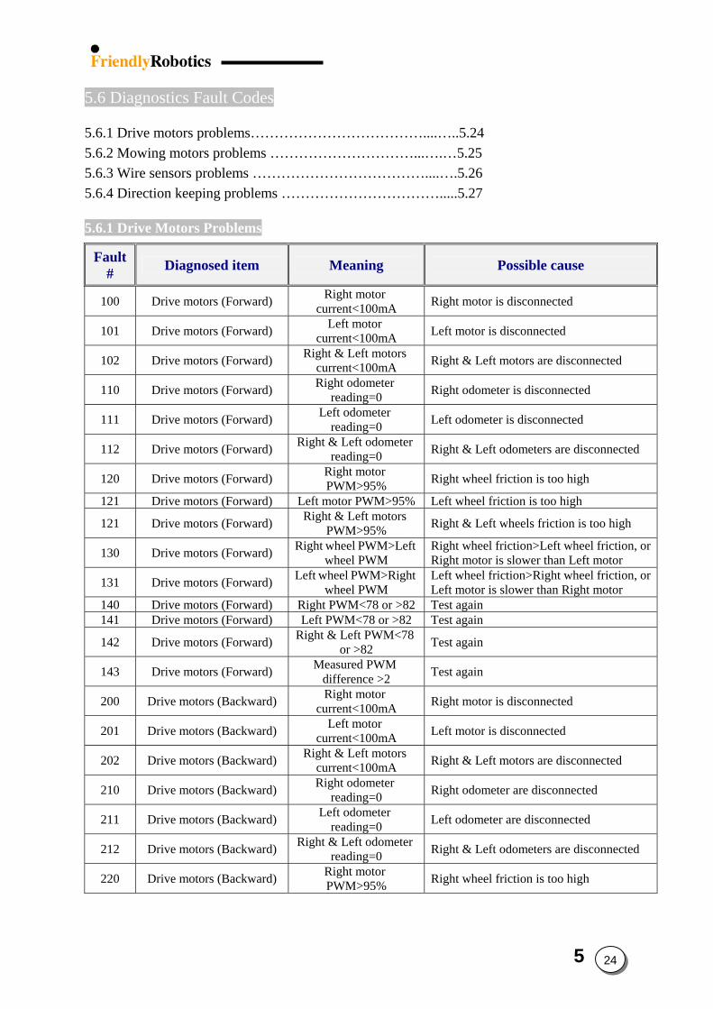
5.6 Diagnostics Fault Codes
5.6.1 Drive motors problems………………………………....…..5.24 5.6.2 Mowing motors problems …………………………...….…5.25 5.6.3 Wire sensors problems ………………………………....….5.26 5.6.4 Direction keeping problems …………………………….....5.27 5.6.1 Drive Motors Problems
Fault# Diagnosed item Meaning Possible cause
100 Drive motors (Forward) Right motor current<100mA Right motor is disconnected
101 Drive motors (Forward) Left motor current<100mA Left motor is disconnected
102 Drive motors (Forward) Right & Left motors current<100mA Right & Left motors are disconnected
110 Drive motors (Forward) Right odometer reading=0 Right odometer is disconnected
111 Drive motors (Forward) Left odometer reading=0 Left odometer is disconnected
112 Drive motors (Forward) Right & Left odometer reading=0 Right & Left odometers are disconnected
120 Drive motors (Forward) Right motor PWM>95% Right wheel friction is too high
121 Drive motors (Forward) Left motor PWM>95% Left wheel friction is too high
121 Drive motors (Forward) Right & Left motors PWM>95% Right & Left wheels friction is too high
130 Drive motors (Forward) Right wheel PWM>Left wheel PWM
Right wheel friction>Left wheel friction, or Right motor is slower than Left motor
131 Drive motors (Forward) Left wheel PWM>Right wheel PWM
Left wheel friction>Right wheel friction, or Left motor is slower than Right motor
140 Drive motors (Forward) Right PWM<78 or >82 Test again 141 Drive motors (Forward) Left PWM<78 or >82 Test again
142 Drive motors (Forward) Right & Left PWM<78 or >82 Test again
143 Drive motors (Forward) Measured PWM difference >2 Test again
200 Drive motors (Backward) Right motor current<100mA Right motor is disconnected
201 Drive motors (Backward) Left motor current<100mA Left motor is disconnected
202 Drive motors (Backward) Right & Left motors current<100mA Right & Left motors are disconnected
210 Drive motors (Backward) Right odometer reading=0 Right odometer are disconnected
211 Drive motors (Backward) Left odometer reading=0 Left odometer are disconnected
212 Drive motors (Backward) Right & Left odometer reading=0 Right & Left odometers are disconnected
220 Drive motors (Backward) Right motor PWM>95% Right wheel friction is too high
5 24
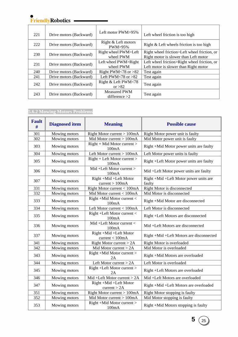
221
Drive motors (Backward)
Left motor PWM>95%
Left wheel friction is too high
222 Drive motors (Backward) Right & Left motors PWM>95% Right & Left wheels friction is too high
230 Drive motors (Backward) Right wheel PWM>Left wheel PWM
Right wheel friction>Left wheel friction, or Right motor is slower than Left motor
231 Drive motors (Backward) Left wheel PWM>Right wheel PWM
Left wheel friction>Right wheel friction, or Left motor is slower than Right motor
240 Drive motors (Backward) Right PWM<78 or >82 Test again 241 Drive motors (Backward) Left PWM<78 or >82 Test again
242 Drive motors (Backward) Right & Left PWM<78 or >82 Test again
243 Drive motors (Backward) Measured PWM difference >2 Test again
5.6.2 Mowing Motors Problems
Fault# Diagnosed item Meaning Possible cause
301 Mowing motors Right Motor current > 100mA Right Motor power unit is faulty302 Mowing motors Mid Motor current > 100mA Mid Motor power unit is faulty
303 Mowing motors Right + Mid Motor current > 100mA Right +Mid Motor power units are faulty
304 Mowing motors Left Motor current > 100mA Left Motor power units is faulty
305 Mowing motors Right + Left Motor current > 100mA Right +Left Motor power units are faulty
306 Mowing motors Mid +Left Motor current > 100mA Mid +Left Motor power units are faulty
307 Mowing motors Right +Mid +Left Motor current > 100mA
Right +Mid +Left Motor power units are faulty
331 Mowing motors Right Motor current < 100mA Right Motor is disconnected332 Mowing motors Mid Motor current < 100mA Mid Motor is disconnected
333 Mowing motors Right +Mid Motor current < 100mA Right +Mid Motor are disconnected
334 Mowing motors Left Motor current < 100mA Left Motor is disconnected
335 Mowing motors Right +Left Motor current < 100mA Right +Left Motors are disconnected
336 Mowing motors Mid +Left Motor current < 100mA Mid +Left Motors are disconnected
337 Mowing motors Right +Mid +Left Motor current < 100mA Right +Mid +Left Motors are disconnected
341 Mowing motors Right Motor current > 2A Right Motor is overloaded342 Mowing motors Mid Motor current > 2A Mid Motor is overloaded
343 Mowing motors Right +Mid Motor current > 2A Right +Mid Motors are overloaded
344 Mowing motors Left Motor current > 2A Left Motor is overloaded
345 Mowing motors Right +Left Motor current > 2A Right +Left Motors are overloaded
346 Mowing motors Mid +Left Motor current > 2A Mid +Left Motors are overloaded
347 Mowing motors Right +Mid +Left Motor current > 2A Right +Mid +Left Motors are overloaded
351 Mowing motors Right Motor current > 100mA Right Motor stopping is faulty352 Mowing motors Mid Motor current > 100mA Mid Motor stopping is faulty
353 Mowing motors Right +Mid Motor current > 100mA Right +Mid Motors stopping is faulty
5 25
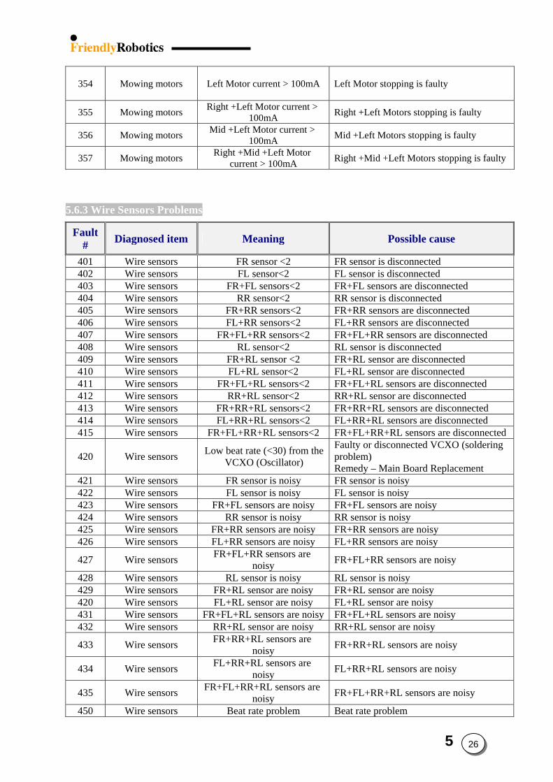
354
Mowing motors
Left Motor current > 100mA Left Motor stopping is faulty
355 Mowing motors Right +Left Motor current > 100mA Right +Left Motors stopping is faulty
356 Mowing motors Mid +Left Motor current > 100mA Mid +Left Motors stopping is faulty
357 Mowing motors Right +Mid +Left Motor current > 100mA Right +Mid +Left Motors stopping is faulty
5.6.3 Wire Sensors Problems
Fault# Diagnosed item Meaning Possible cause
401 Wire sensors FR sensor <2 FR sensor is disconnected402 Wire sensors FL sensor<2 FL sensor is disconnected403 Wire sensors FR+FL sensors<2 FR+FL sensors are disconnected404 Wire sensors RR sensor<2 RR sensor is disconnected405 Wire sensors FR+RR sensors<2 FR+RR sensors are disconnected406 Wire sensors FL+RR sensors<2 FL+RR sensors are disconnected407 Wire sensors FR+FL+RR sensors<2 FR+FL+RR sensors are disconnected408 Wire sensors RL sensor<2 RL sensor is disconnected409 Wire sensors FR+RL sensor <2 FR+RL sensor are disconnected410 Wire sensors FL+RL sensor<2 FL+RL sensor are disconnected411 Wire sensors FR+FL+RL sensors<2 FR+FL+RL sensors are disconnected412 Wire sensors RR+RL sensor<2 RR+RL sensor are disconnected413 Wire sensors FR+RR+RL sensors<2 FR+RR+RL sensors are disconnected414 Wire sensors FL+RR+RL sensors<2 FL+RR+RL sensors are disconnected415 Wire sensors FR+FL+RR+RL sensors<2 FR+FL+RR+RL sensors are disconnected
420 Wire sensors Low beat rate (<30) from the VCXO (Oscillator)
Faulty or disconnected VCXO (soldering problem) Remedy – Main Board Replacement
421 Wire sensors FR sensor is noisy FR sensor is noisy422 Wire sensors FL sensor is noisy FL sensor is noisy423 Wire sensors FR+FL sensors are noisy FR+FL sensors are noisy424 Wire sensors RR sensor is noisy RR sensor is noisy425 Wire sensors FR+RR sensors are noisy FR+RR sensors are noisy426 Wire sensors FL+RR sensors are noisy FL+RR sensors are noisy
427 Wire sensors FR+FL+RR sensors are noisy FR+FL+RR sensors are noisy
428 Wire sensors RL sensor is noisy RL sensor is noisy429 Wire sensors FR+RL sensor are noisy FR+RL sensor are noisy420 Wire sensors FL+RL sensor are noisy FL+RL sensor are noisy431 Wire sensors FR+FL+RL sensors are noisy FR+FL+RL sensors are noisy432 Wire sensors RR+RL sensor are noisy RR+RL sensor are noisy
433 Wire sensors FR+RR+RL sensors are noisy FR+RR+RL sensors are noisy
434 Wire sensors FL+RR+RL sensors are noisy FL+RR+RL sensors are noisy
435 Wire sensors FR+FL+RR+RL sensors are noisy FR+FL+RR+RL sensors are noisy
450 Wire sensors Beat rate problem Beat rate problem
5 26
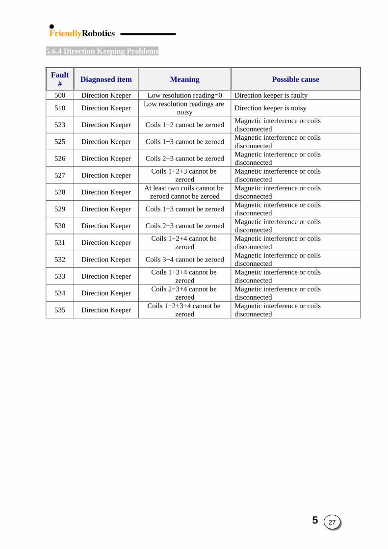
5.6.4 Direction Keeping Problems
Fault# Diagnosed item Meaning Possible cause
500 Direction Keeper Low resolution reading=0 Direction keeper is faulty
510 Direction Keeper Low resolution readings are noisy Direction keeper is noisy
523 Direction Keeper Coils 1+2 cannot be zeroed Magnetic interference or coils disconnected
525 Direction Keeper Coils 1+3 cannot be zeroed Magnetic interference or coils disconnected
526 Direction Keeper Coils 2+3 cannot be zeroed Magnetic interference or coils disconnected
527 Direction Keeper Coils 1+2+3 cannot be zeroed
Magnetic interference or coils disconnected
528 Direction Keeper At least two coils cannot be zeroed cannot be zeroed
Magnetic interference or coils disconnected
529 Direction Keeper Coils 1+3 cannot be zeroed Magnetic interference or coils disconnected
530 Direction Keeper Coils 2+3 cannot be zeroed Magnetic interference or coils disconnected
531 Direction Keeper Coils 1+2+4 cannot be zeroed
Magnetic interference or coils disconnected
532 Direction Keeper Coils 3+4 cannot be zeroed Magnetic interference or coils disconnected
533 Direction Keeper Coils 1+3+4 cannot be zeroed
Magnetic interference or coils disconnected
534 Direction Keeper Coils 2+3+4 cannot be zeroed
Magnetic interference or coils disconnected
535 Direction Keeper Coils 1+2+3+4 cannot be zeroed
Magnetic interference or coils disconnected
5 27
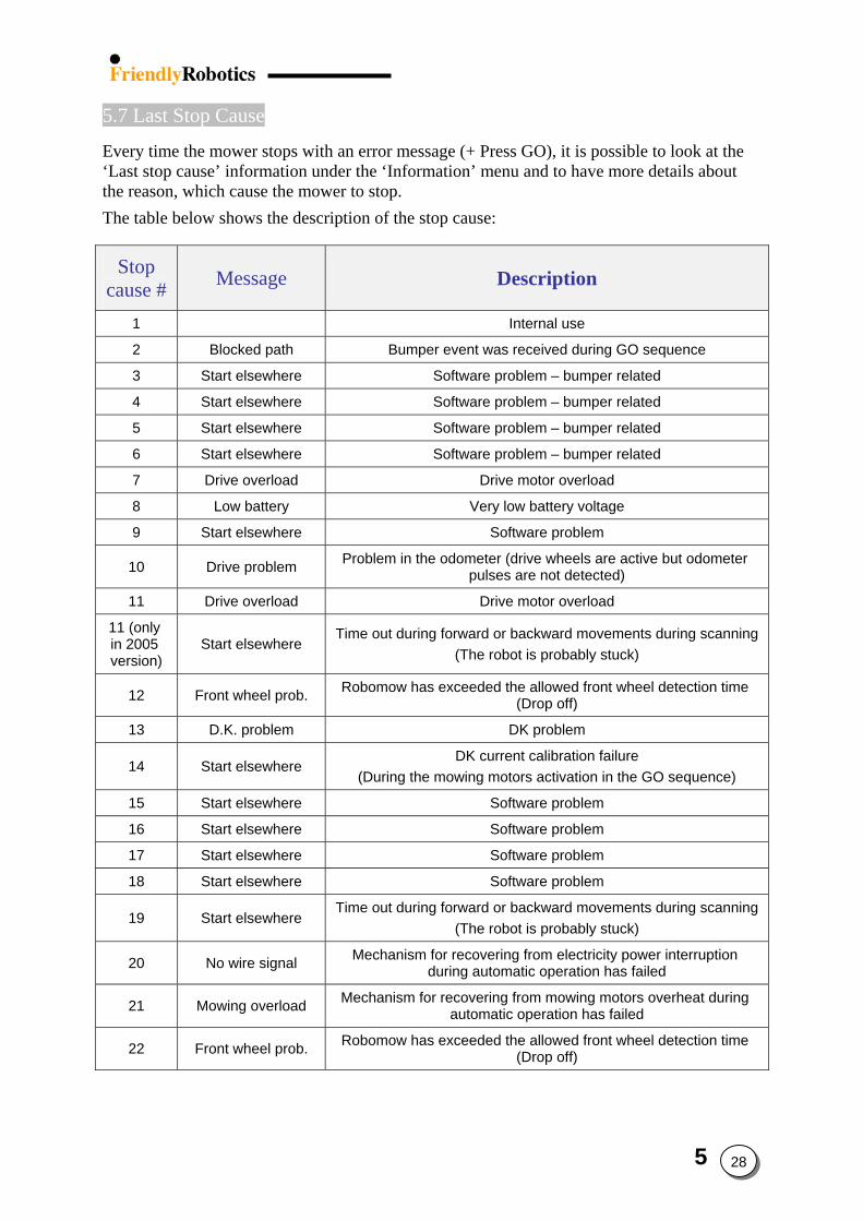
5.7 Last Stop Cause
Every time the mower stops with an error message (+ Press GO), it is possible to look at the ‘Last stop cause’ information under the ‘Information’ menu and to have more details about the reason, which cause the mower to stop.
The table below shows the description of the stop cause:
Stop cause # Message Description
1 Internal use
2 Blocked path Bumper event was received during GO sequence
3 Start elsewhere Software problem – bumper related
4 Start elsewhere Software problem – bumper related
5 Start elsewhere Software problem – bumper related
6 Start elsewhere Software problem – bumper related
7 Drive overload Drive motor overload
8 Low battery Very low battery voltage
9 Start elsewhere Software problem
10 Drive problem Problem in the odometer (drive wheels are active but odometer pulses are not detected)
11 Drive overload Drive motor overload
11 (only in 2005 version)
Start elsewhere Time out during forward or backward movements during scanning
(The robot is probably stuck)
12 Front wheel prob. Robomow has exceeded the allowed front wheel detection time (Drop off)
13 D.K. problem DK problem
14 Start elsewhere DK current calibration failure
(During the mowing motors activation in the GO sequence)
15 Start elsewhere Software problem
16 Start elsewhere Software problem
17 Start elsewhere Software problem
18 Start elsewhere Software problem
19 Start elsewhere Time out during forward or backward movements during scanning
(The robot is probably stuck)
20 No wire signal Mechanism for recovering from electricity power interruption during automatic operation has failed
21 Mowing overload Mechanism for recovering from mowing motors overheat during automatic operation has failed
22 Front wheel prob. Robomow has exceeded the allowed front wheel detection time (Drop off)
5 28
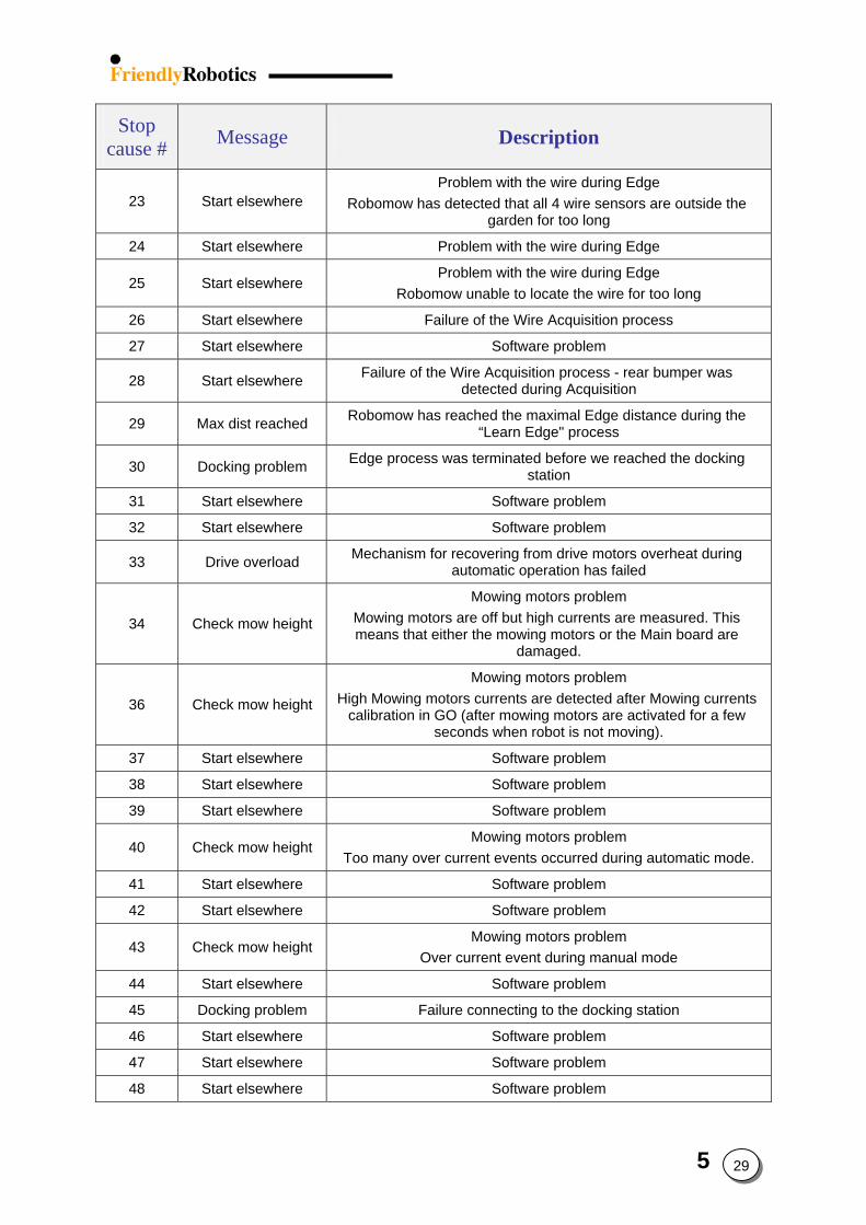
Stop cause # Message Description
23 Start elsewhere Problem with the wire during Edge
Robomow has detected that all 4 wire sensors are outside the garden for too long
24 Start elsewhere Problem with the wire during Edge
25 Start elsewhere Problem with the wire during Edge
Robomow unable to locate the wire for too long
26 Start elsewhere Failure of the Wire Acquisition process
27 Start elsewhere Software problem
28 Start elsewhere Failure of the Wire Acquisition process - rear bumper was detected during Acquisition
29 Max dist reached Robomow has reached the maximal Edge distance during the “Learn Edge" process
30 Docking problem Edge process was terminated before we reached the docking station
31 Start elsewhere Software problem
32 Start elsewhere Software problem
33 Drive overload Mechanism for recovering from drive motors overheat during automatic operation has failed
34 Check mow height
Mowing motors problem Mowing motors are off but high currents are measured. This means that either the mowing motors or the Main board are
damaged.
36 Check mow height
Mowing motors problem High Mowing motors currents are detected after Mowing currents
calibration in GO (after mowing motors are activated for a few seconds when robot is not moving).
37 Start elsewhere Software problem
38 Start elsewhere Software problem
39 Start elsewhere Software problem
40 Check mow height Mowing motors problem
Too many over current events occurred during automatic mode.
41 Start elsewhere Software problem
42 Start elsewhere Software problem
43 Check mow height Mowing motors problem
Over current event during manual mode
44 Start elsewhere Software problem
45 Docking problem Failure connecting to the docking station
46 Start elsewhere Software problem
47 Start elsewhere Software problem
48 Start elsewhere Software problem
5 29
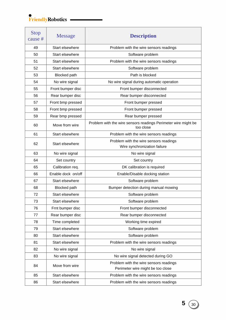
Stop cause # Message Description
49 Start elsewhere Problem with the wire sensors readings
50 Start elsewhere Software problem
51 Start elsewhere Problem with the wire sensors readings
52 Start elsewhere Software problem
53 Blocked path Path is blocked
54 No wire signal No wire signal during automatic operation
55 Front bumper disc Front bumper disconnected
56 Rear bumper disc Rear bumper disconnected
57 Front bmp pressed Front bumper pressed
58 Front bmp pressed Front bumper pressed
59 Rear bmp pressed Rear bumper pressed
60 Move from wire Problem with the wire sensors readings Perimeter wire might be too close
61 Start elsewhere Problem with the wire sensors readings
62 Start elsewhere Problem with the wire sensors readings
Wire synchronization failure
63 No wire signal No wire signal
64 Set country Set country
65 Calibration req. DK calibration is required
66 Enable dock on/off Enable/Disable docking station
67 Start elsewhere Software problem
68 Blocked path Bumper detection during manual mowing
72 Start elsewhere Software problem
73 Start elsewhere Software problem
76 Frnt bumper disc Front bumper disconnected
77 Rear bumper disc Rear bumper disconnected
78 Time completed Working time expired
79 Start elsewhere Software problem
80 Start elsewhere Software problem
81 Start elsewhere Problem with the wire sensors readings
82 No wire signal No wire signal
83 No wire signal No wire signal detected during GO
84 Move from wire Problem with the wire sensors readings
Perimeter wire might be too close
85 Start elsewhere Problem with the wire sensors readings
86 Start elsewhere Problem with the wire sensors readings
5 30
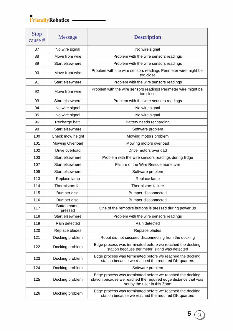
Stop cause # Message Description
87 No wire signal No wire signal
88 Move from wire Problem with the wire sensors readings
89 Start elsewhere Problem with the wire sensors readings
90 Move from wire Problem with the wire sensors readings Perimeter wire might be too close
91 Start elsewhere Problem with the wire sensors readings
92 Move from wire Problem with the wire sensors readings Perimeter wire might be too close
93 Start elsewhere Problem with the wire sensors readings
94 No wire signal No wire signal
95 No wire signal No wire signal
96 Recharge batt. Battery needs recharging
98 Start elsewhere Software problem
100 Check mow height Mowing motors problem
101 Mowing Overload Mowing motors overload
102 Drive overload Drive motors overload
103 Start elsewhere Problem with the wire sensors readings during Edge
107 Start elsewhere Failure of the Wire Rescue maneuver
109 Start elsewhere Software problem
113 Replace lamp Replace lamp
114 Thermistors fail Thermistors failure
115 Bumper disc. Bumper disconnected
116 Bumper disc. Bumper disconnected
117 ‘Button name’ pressed One of the remote’s buttons is pressed during power up
118 Start elsewhere Problem with the wire sensors readings
119 Rain detected Rain detected
120 Replace blades Replace blades
121 Docking problem Robot did not succeed disconnecting from the docking
122 Docking problem Edge process was terminated before we reached the docking station because perimeter island was detected
123 Docking problem Edge process was terminated before we reached the docking station because we reached the required DK quarters
124 Docking problem Software problem
125 Docking problem Edge process was terminated before we reached the docking
station because we reached the required edge distance that was set by the user in this Zone
126 Docking problem Edge process was terminated before we reached the docking station because we reached the required DK quarters
5 31
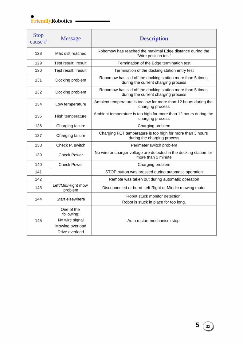
Stop cause # Message Description
128 Max dist reached Robomow has reached the maximal Edge distance during the “Wire position test"
129 Test result: ‘result’ Termination of the Edge termination test
130 Test result: ‘result’ Termination of the docking station entry test
131 Docking problem Robomow has slid off the docking station more than 5 times during the current charging process
132 Docking problem Robomow has slid off the docking station more than 5 times during the current charging process
134 Low temperature Ambient temperature is too low for more than 12 hours during the charging process
135 High temperature Ambient temperature is too high for more than 12 hours during the charging process
136 Charging failure Charging problem
137 Charging failure Charging FET temperature is too high for more than 3 hours during the charging process
138 Check P. switch Perimeter switch problem
139 Check Power No wire or charger voltage are detected in the docking station for more than 1 minute
140 Check Power Charging problem
141 STOP button was pressed during automatic operation
142 Remote was taken out during automatic operation
143 Left/Mid/Right mow problem Disconnected or burnt Left Right or Middle mowing motor
144 Start elsewhere Robot stuck monitor detection.
Robot is stuck in place for too long.
145
One of the following:
No wire signal Mowing overload
Drive overload
Auto restart mechanism stop.
5 32
6 1
6. Friendly Robotics Procedures and policies
6.1 Warranty claims……………………………………………………... 6.2 6.1.1 Warranty claims procedure………………………………………. 6.2 6.1.2 Friendly Coding System (FCS)………………………………….. 6.9
6.2 Robomow Power Pack Charging Policy……………………………. 6.17 6.2.1 Overview…………………………………….…………………… 6.17 6.2.2 Charging procedure…………………………………….………... 6.18 6.2.3 Storage and shelf life……………………………………………. 6.21 6.2.4 Closure…………………………………….……………………... 6.21
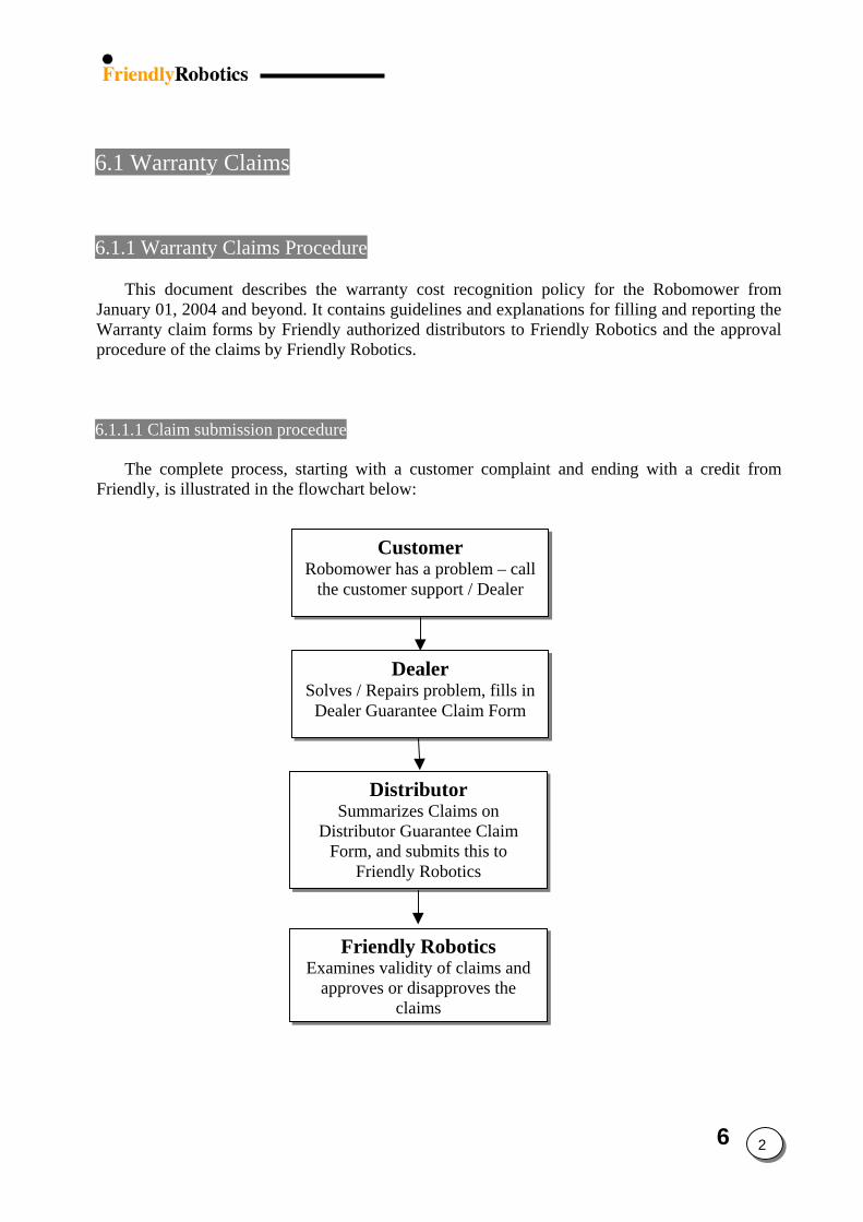
6.1 Warranty Claims 6.1.1 Warranty Claims Procedure
This document describes the warranty cost recognition policy for the Robomower from January 01, 2004 and beyond. It contains guidelines and explanations for filling and reporting the Warranty claim forms by Friendly authorized distributors to Friendly Robotics and the approval procedure of the claims by Friendly Robotics.
6.1.1.1 Claim submission procedure
The complete process, starting with a customer complaint and ending with a credit from Friendly, is illustrated in the flowchart below:
Exaap
Distributor Summarizes Claims on
Distributor Guarantee Claim Form, and submits this to
Friendly Robotics
Dealer Solves / Repairs problem, fills in
Dealer Guarantee Claim Form
Customer Robomower has a problem – call
the customer support / Dealer
Friendly Robotics mines validity of claims and proves or disapproves the
claims
6 2
6 3
6.1.1.1.1 Customer Complaint
In case of a problem with the Robomower, the customer should call to the Customer Support or the nearest local dealer for assistance.
6.1.1.1.2 Dealers Activities
A valid proof of purchase is required for warranty repairs. The Dealer should try solving the
problem over the phone, as described in the Problem Analysis Flowcharts section of the Service Guide. If the problem was not solved over the phone, either the customer should bring/send the faulty mower to the dealer or the dealer should visit the customer’s residence, depending on the problem type and the dealer’s policy.
If the dealer cannot solve/repair the problem, it should be communicated to the Distributor.
If the dealer solves the problem and decides to claim the repair expenses from Friendly, a written Warranty Claim should be sent to the Distributor. All service calls for which claims were made during one month should be sent to the Distributor during the following month. The dealer MUST provide the following information for EVERY repair of every claim:
Dealer name Service date Product and model name Serial number Date of product purchase by the customer Warranty period end date Problem description (FCS code) Parts required to complete repair Cost claimed (labor time and spare parts cost)
All these items are required by Friendly Robotics for every claim and a claim cannot be
considered unless all of this information was provided by the dealer and received by Friendly. Together with this monthly report, all faulty parts identified and associated with a specific claim, should be kept by the Dealer for 90 days from repair or until the claim has been paid, whichever comes first.
The warranty period for products is defined in the warranty card provided with each unit. Any nominated dealer of Distributor may repair any product during this period. Any such claim shall be submitted to Distributor on a monthly basis. The warranty claim made by the Dealer should be provided to Distributor no later than 60 days from the date of the repair.
IMPORTANT! Claims submitted to Friendly Robotics after more than 90 days from the repair date will not be recognized. It is important to submit the claims you have on a monthly base, so the approval process will be completed on time.
6 4
6.1.1.1.3 Distributor Activities
The distributor should review every claim submitted by a dealer and verify the following:
- Dealer provided all required information and details. - All faulty spare parts were kept or supplied with the claim and were identified. - The product repaired was under Warranty. - The claim is logical in terms of applied solution, time claimed and total claim amount.
A Claim will be approved by the Distributor and included in the Claims report sent to Friendly, only if all of the above conditions were met.
The Distributor should summarize all approved Warranty claims submitted by the Dealers on
an Excel sheet called Distributor Warranty Claim Form (see appendix A). A separated report should be formed for every product model (i.e. RL500, RL800, RL550, RL850 and RL1000). At the top of every report the following should be written:
Distributor name Country Product / model Claim period (month)
The form includes the following details for each claim:
Dealer’s claim number Product serial number Date of repair Date of sale Parts used Time claimed (time cost, spares cost and administration cost) FCS Code (codes describe the failure).
The Distributor should summarize Warranty Claim received from the Dealers on a monthly
basis and send the claim to Friendly Robotics every month for the month preceding it. The Claims should be submitted to Friendly no later than 90 days from the date of the repair.
The Distributor should hold the faulty parts for 90 days from repair or until the claim has been paid, whichever comes first.
6.1.1.1.4 Friendly Robotics Activities
Friendly Robotics will examine every claim. In order to expedite the claim examination process, all required details should be provided in the Warranty Claims report in order to prevent delay in the approval process. Whenever it will be deemed necessary by Friendly to analyze a faulty part, the part should be sent to Friendly. Friendly reserves the right to ask for any faulty part that was claimed for to be shipped for inspection.
6 5
Claims approval by Friendly’s Customer Support will be sent both to the Distributor and to Friendly’s Finance Department. The approval received from Friendly Customer Support will enable the Distributor to scrap all the faulty parts defined under a specific report, which had been approved. Friendly Robotics Finance Department will send a credit note that can be deducted from future payments to Friendly Robotics.
6.1.1.2 Distributor Warranty Claim Form filling instructions
The Distributor should summarize the Warranty Claims on the Excel file supplied by Friendly
Robotics (see appendix A). The report should be submitted on a monthly basis. This form is identical to all distributors and is supplied by Friendly Robotics. The distributor should fill only the yellow cells in the ‘Warranty Claims Report’ spreadsheet; the second and the third spreadsheets used as data inputs to fulfill the first spreadsheet; the fourth spreadsheet is automatically filled summarizing the total parts used.
The following information should be filled in the first spreadsheet:
1. Distributor (cell C6): the name of the distributor company. 2. Country (cell C7): the country where the distributor is active. 3. Product / Model (cell C8): the name of the product / model. Every report should summarize
the Warranty claims of each model separately. 4. Claim Period (month) (cell N6): the month, which this report is referring to. One report
should be sent every month for each product. Do not separate the claims for more than one report in the same month.
5. Shop rate (€ per hour) (cell N7): The labor cost of the dealer per hour. 6. Claim Date (cell N8): the date, which the Warranty Claims report is sent to Friendly
Robotics. 7. Dealer’s Claim No. (column B): the number of the claim received from the dealer. 8. Serial No. (column C): Serial number of the product – it can be found under the Power
Pack. The format of the serial number is IRL with another 10 digits (IRLxxxxxxxxxx) – do no make any shortening.
9. Operation Hours (column D): total operation hours of the mower. 10. Date of Repair (column E): Date the unit was repaired by the dealer. 11. Date of Sale (column F): Date the product was purchased by the customer. 12. Part used (column H): Fill the item number (changed from 1,2,3 to 128) of the part used,
taken from the second spreadsheet ‘Parts List & Cost & Time’ (column A). Press cell number G11 (Part No.) in the first spreadsheet ‘Warranty Claims Report’ to show the part list.
13. Part Description, Labor Time and Part Cost (columns I to K): These columns are automatically filled from the data appeared in the second spreadsheet ‘Parts List & Cost & Time’ (for more details about the time claimed calculation refer to appendix B).
14. Part used (columns M, R and V): These are optional columns to be filled in case there is more than one part replaced in the same claim.
6 6
15. Part Description, Labor Time and Part Cost (for the second, third and fourth part in
the same claim): In such case, where more than one part is used to repair the unit, the labor time for the second and third parts is taken from column E at the second spreadsheet ‘Parts List & Cost & Time’, as there is no need to add again the time to remove the cover and the time required to test the mower at the end of the repair.
16. Summary (columns AA to AE): All these columns are automatically summarized. 17. Other Cost (column AC): this column is reserved for cases, for which the dealer repairs the
unit without replacing any part. In such case the details of the ‘Other Cost’ should be filled in columns AU, which describes the details of the repair and AQ which summaries the repair time.
18. Total (column AE): The total cost, calculated automatically as sum of all the costs related mentioned before.
19. FCS Code: See detailed explanation in paragraph 6.2 6.1.1.3 Items and Conditions Not Covered under Warranty:
1. Normal wear and tear, including blades and fading of paint or plastic parts. 2. Any product or part that has been altered, misused, abused or requires replacement or repair
due to accidents or lack of proper maintenance. 3. Cost of Setup (installation or reinstallation of the perimeter wire), removal of installation or
any costs or damages associated with improper installation or use of product.
4. Any product that has been opened, repaired, modified or altered by anyone other than a Friendly Robotics authorized repair technician.
5. Repairs necessary due to improper battery care, electrical supply irregularities, or failure to properly prepare the mower or battery for winter storage or other extended storage periods.
6. Repairs necessary due to water damage, other than incidental rain exposure.
7. Transportation costs. The owner bears all responsibility for transportation costs to an authorized Friendly Robotics service.
8. Power Pack warranty is limited to 18 months from manufacturing date (printed on the 4 first digits in the product serial number) or one year from date of purchase, whichever comes first.
9. Robomower replacement is not approved under warranty, unless written approval is given from Friendly Robotics Customer Support.
6 7
6.1.2 Friendly Coding System (FCS) Explanation
Friendly Coding System (FCS) is Friendly’s method for recording and tracking customer complaints about the Robomower performance. The purpose of the FCS is to systematically and logically capture and organize the information coming from the customers, the evolution of every complaint and repair, in a way that will be easier to classify and analyze the data.
Instead of writing out a textual report on every customer complaint or faulty unit, a code is inserted and it details the customer complaint, root cause and what was done to solve the problem. In addition, the FCS will allow for easier data presentation in different levels and views to measure the Robomower quality in various metrics.
In FCS, every case (customer complaint / service call) consists of 3 difference fields:
1) Customer Observation Code 2) Failure Code 3) Repair Code
6.1.2.1 Customer Observation
The Customer Observation Code is a record of the customer complaint. It should be logged by the call center/service provider and include the customer perception of the problem and the conclusion of the interviewer based on the answers provided by the customer. The Customer Observation Code is divided into groups according to their families (Power Pack, Manual Controller, Mowing and so on). Where available you can find the relevant ‘problem analysis flowchart’ for the customer observation.
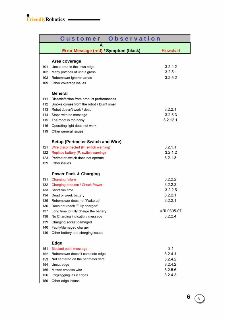
6 8
C u s t o m e r O b s e r v a t i o n A
Error Message (red) / Symptom ( Flowchart
Wire disconnected (P. switch warning)Replace battery (P. switch warning)
Charging failure Charging problem / Check Power
Blocked path’ message
black)
Area coverage101 Uncut area in the lawn edge 3.2.4.2102 Many patches of uncut grass 3.2.5.1103 Robomower ignores areas 3.2.5.2109 Other coverage issues
General111 Dissatisfaction from product performances112 Smoke comes from the robot / Burnt smell113 Robot doesn't work / dead 3.2.2.1 114 Stops with no message 3.2.5.3115 The robot is too noisy 3.2.12.1 116 Operating light does not work119 Other general issues
Setup (Perimeter Switch and Wire)121 3.2.1.1 122 3.2.1.2123 Perimeter switch does not operate 3.2.1.3 129 Other issues
Power Pack & Charging131 3.2.2.2 132 3.2.2.3 133 Short run time 3.2.2.5134 Dead or week battery 3.2.2.1 135 Robomower does not 'Wake up' 3.2.2.1 136 Does not reach 'Fully charged'137 Long time to fully charge the battery #RL0305-07138 No Charging indication/ message 3.2.2.4 139 Charging socket damaged140 Faulty/damaged charger149 Other battery and charging issues
Edge151 3.1152 Robomower doesn't complete edge 3.2.4.1 153 Not centered on the perimeter wire 3.2.4.2 154 Uncut edge 3.2.4.2 155 Mower crocess wire 3.2.5.6 156 ‘zigzagging’ as it edges 3.2.4.3 159 Other edge issues
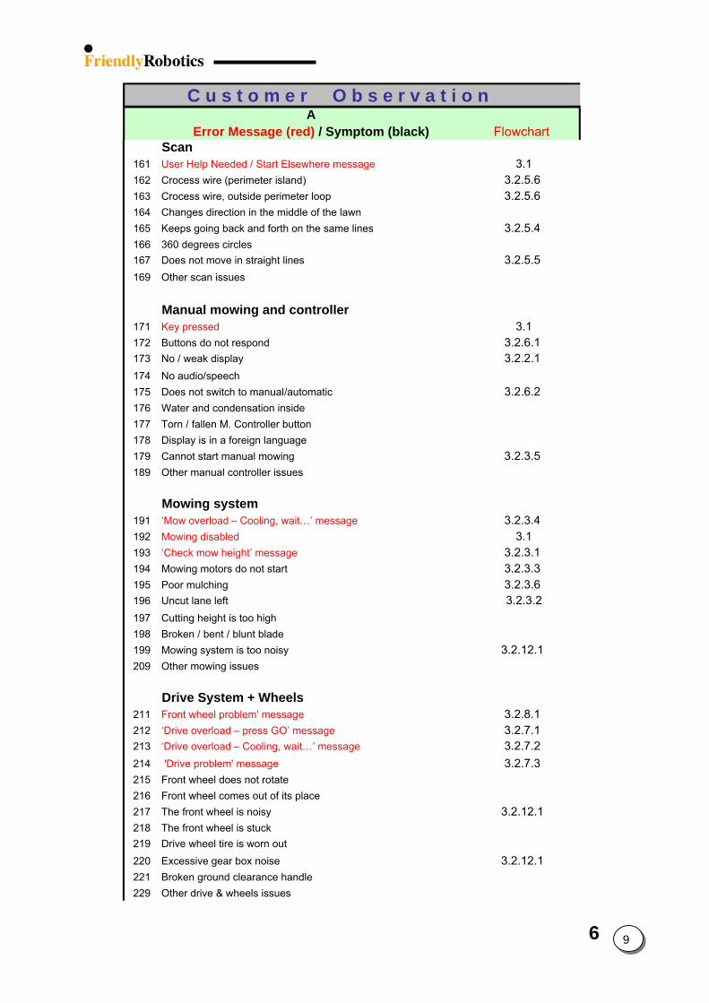
6 9
C u s t o m e r O b s e r v a t i o n A
Error Message (red) / Symptom ( Flowchartblack)
Scan
161 User Help Needed / Start Elsewhere message
Key pressed
‘Mow overload – Cooling, wait…’ messageMowing disabled‘Check mow height’ message
Front wheel problem' message‘Drive overload – press GO’ message‘Drive overload – Cooling, wait…’ message 'Drive problem' message
3.1162 Crocess wire (perimeter island) 3.2.5.6 163 Crocess wire, outside perimeter loop 3.2.5.6 164 Changes direction in the middle of the lawn165 Keeps going back and forth on the same lines 3.2.5.4 166 360 degrees circles167 Does not move in straight lines 3.2.5.5 169 Other scan issues
Manual mowing and controller171 3.1172 Buttons do not respond 3.2.6.1 173 No / weak display 3.2.2.1 174 No audio/speech175 Does not switch to manual/automatic 3.2.6.2 176 Water and condensation inside 177 Torn / fallen M. Controller button178 Display is in a foreign language179 Cannot start manual mowing 3.2.3.5 189 Other manual controller issues
Mowing system191 3.2.3.4 192 3.1193 3.2.3.1 194 Mowing motors do not start 3.2.3.3 195 Poor mulching 3.2.3.6 196 Uncut lane left 3.2.3.2197 Cutting height is too high198 Broken / bent / blunt blade199 Mowing system is too noisy 3.2.12.1 209 Other mowing issues
Drive System + Wheels211 3.2.8.1 212 3.2.7.1 213 3.2.7.2 214 3.2.7.3 215 Front wheel does not rotate216 Front wheel comes out of its place217 The front wheel is noisy 3.2.12.1 218 The front wheel is stuck219 Drive wheel tire is worn out220 Excessive gear box noise 3.2.12.1 221 Broken ground clearance handle229 Other drive & wheels issues
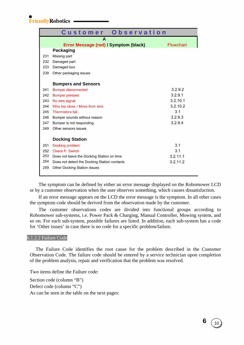
6 10
C u s t o m e r O b s e r v a t i o n A
Error Message (red) / Symptom (black) Flowchart
Packaging231 Missing part232 Damaged part233 Damaged box239 Other packaging issues
Bumpers and Sensors241 Bumper disconnected
Bumper pressedNo wire signalWire too close / Move from wireThermistors fail.
Docking problemCheck P. Switch
3.2.9.2242 3.2.9.1 243 3.2.10.1244 3.2.10.2245 3.1246 Bumper sounds without reason 3.2.9.3 247 Bumper is not responding 3.2.9.4 249 Other sensors issues
Docking Station251 3.1252 3.1253 Does not leave the Docking Station on time 3.2.11.1 254 Does not detect the Docking Station contacts 3.2.11.2 259 Other Docking Station issues
The symptom can be defined by either an error message displayed on the Robomower LCD
or by a customer observation when the user observes something, which causes dissatisfaction. If an error message appears on the LCD the error message is the symptom. In all other cases
the symptom code should be derived from the observation made by the customer. The customer observations codes are divided into functional groups according to
Robomower sub-systems, i.e. Power Pack & Charging, Manual Controller, Mowing system, and so on. For each sub-system, possible failures are listed. In addition, each sub-system has a code for ‘Other issues’ in case there is no code for a specific problem/failure.
6.1.2.2 Failure Code
The Failure Code identifies the root cause for the problem described in the Customer
Observation Code. The failure code should be entered by a service technician upon completion of the problem analysis, repair and verification that the problem was resolved.
Two items define the Failure code:
Section code (column “B”) Defect code (column “C”) As can be seen in the table on the next pages:
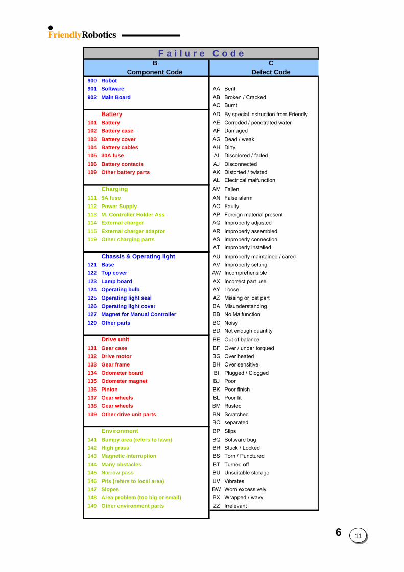
6 11
F a i l u r e C o d eB C
Component Code Defect Code900 Robot 901 Software AA Bent902 Main Board AB Broken / Cracked
AC Burnt Battery
101 Battery102 Battery case103 Battery cover104 Battery cables105 30A fuse106 Battery contacts109 Other battery parts
Drive unit131 Gear case132 Drive motor133 Gear frame134 Odometer board135 Odometer magnet136 Pinion137 Gear wheels138 Gear wheels139 Other drive unit parts
AD By special instruction from FriendlyAE Corroded / penetrated water AF DamagedAG Dead / weakAH DirtyAI Discolored / fadedAJ DisconnectedAK Distorted / twistedAL Electrical malfunction
Charging AM Fallen111 5A fuse AN False alarm112 Power Supply AO Faulty113 M. Controller Holder Ass. AP Foreign material present114 External charger AQ Improperly adjusted115 External charger adaptor AR Improperly assembled119 Other charging parts AS Improperly connection
AT Improperly installedChassis & Operating light AU Improperly maintained / cared
121 Base AV Improperly setting122 Top cover AW Incomprehensible123 Lamp board AX Incorrect part use124 Operating bulb AY Loose125 Operating light seal AZ Missing or lost part126 Operating light cover BA Misunderstanding127 Magnet for Manual Controller BB No Malfunction129 Other parts BC Noisy
BD Not enough quantityBE Out of balanceBF Over / under torquedBG Over heated BH Over sensitiveBI Plugged / CloggedBJ PoorBK Poor finishBL Poor fitBM RustedBN ScratchedBO separated
Environment BP Slips141 Bumpy area (refers to lawn) BQ Software bug142 High grass BR Stuck / Locked143 Magnetic interruption BS Torn / Punctured144 Many obstacles BT Turned off145 Narrow pass BU Unsuitable storage146 Pits (refers to local area) BV Vibrates147 Slopes BW Worn excessively148 Area problem (too big or small) BX Wrapped / wavy149 Other environment parts ZZ Irrelevant
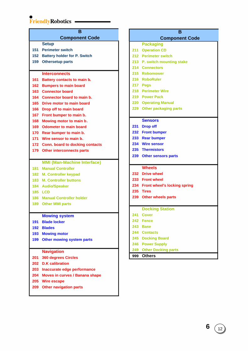
6 12
MMI (Man-Machine Interface)181 Manual Controller182 M. Controller keypad183 M. Controller buttons184 Audio/Speaker185 LCD186 Manual Controller holder189 Other MMI parts
Mowing system191 Blade locker192 Blades193 Mowing motor199 Other mowing system parts
Setup151 Perimeter switch152 Battery holder for P. Switch159 Othersetup parts
Interconnects161 Battery contacts to main b.162 Bumpers to main board163 Connector board164 Connector board to main b.165 Drive motor to main board166 Drop off to main board167 Front bumper to main b.168 Mowing motor to main b.169 Odometer to main board170 Rear bumper to main b.171 Wire sensor to main b.172 Conn. board to docking contacts179 Other interconnects parts
Navigation201 360 degrees Circles202 D.K calibration203 Inaccurate edge performance204 Moves in curves / Banana shape205 Wire escape209 Other navigation parts
Packaging211 Operation CD212 Perimeter switch213 P. switch mounting stake214 Connectors215 Robomower216 RoboRuler217 Pegs218 Perimeter Wire219 Power Pack220 Operating Manual229 Other packaging parts
Sensors231 Drop off232 Front bumper233 Rear bumper234 Wire sensor235 Thermistors239 Other sensors parts
Wheels232 Drive wheel233 Front wheel234 Front wheel's locking spring235 Tires239 Other wheels parts
Docking Station241 Cover242 Fence243 Base244 Contacts245 Docking Board246 Power Supply249 Other Docking parts999 Others
BComponent Code
B
Component Code
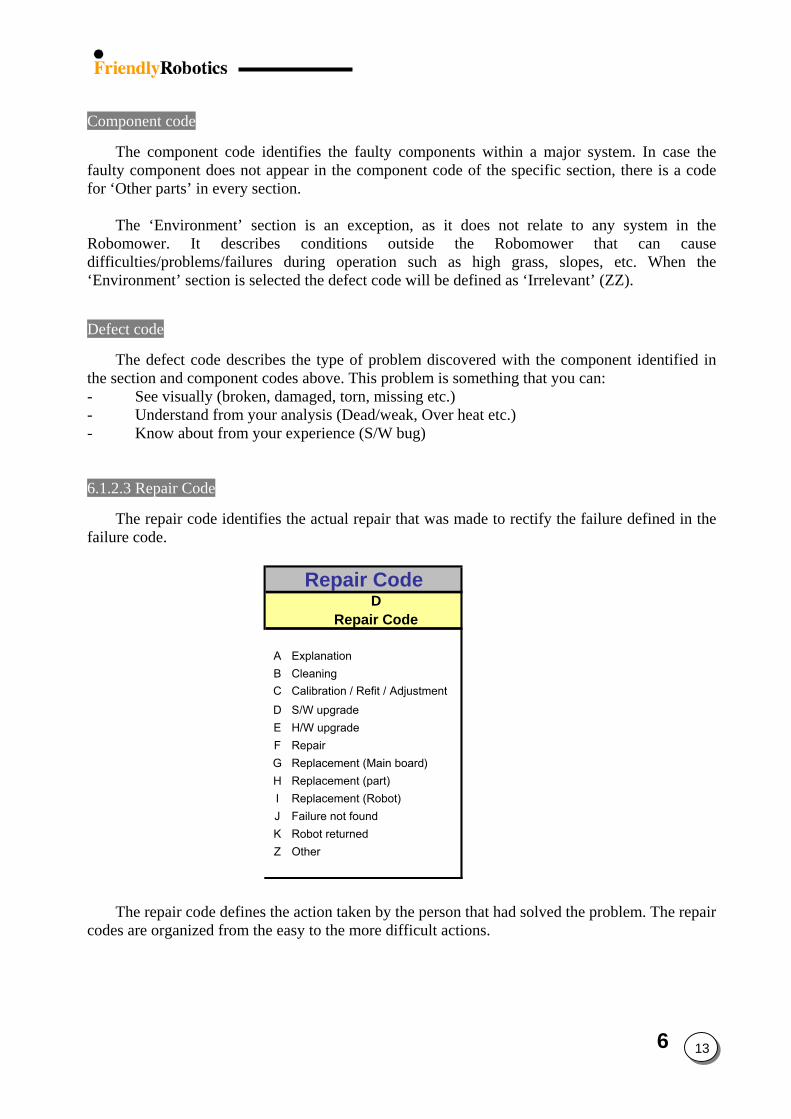
6 13
Component code
The component code identifies the faulty components within a major system. In case the faulty component does not appear in the component code of the specific section, there is a code for ‘Other parts’ in every section.
The ‘Environment’ section is an exception, as it does not relate to any system in the Robomower. It describes conditions outside the Robomower that can cause difficulties/problems/failures during operation such as high grass, slopes, etc. When the ‘Environment’ section is selected the defect code will be defined as ‘Irrelevant’ (ZZ).
Defect code
The defect code describes the type of problem discovered with the component identified in the section and component codes above. This problem is something that you can: - See visually (broken, damaged, torn, missing etc.) - Understand from your analysis (Dead/weak, Over heat etc.) - Know about from your experience (S/W bug) 6.1.2.3 Repair Code
The repair code identifies the actual repair that was made to rectify the failure defined in the
failure code.
Repair CodeD
Repair Code
A ExplanationB CleaningC Calibration / Refit / AdjustmentD S/W upgradeE H/W upgradeF RepairG Replacement (Main board)H Replacement (part)I Replacement (Robot)J Failure not foundK Robot returnedZ Other
The repair code defines the action taken by the person that had solved the problem. The repair codes are organized from the easy to the more difficult actions.
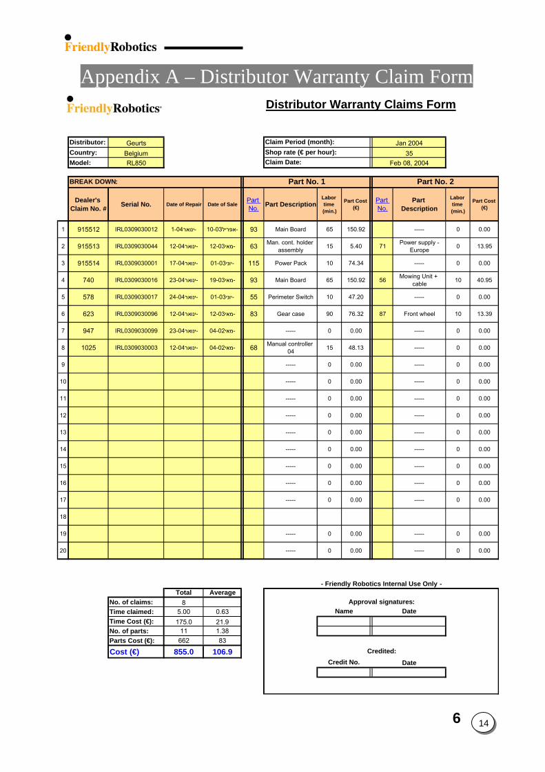
6 14
Appendix A – Distributor Warranty Claim Form Distributor Warranty Claims Form
Distributor: GeurtsCountry: BelgiumModel: RL850
Dealer's Claim No. # Serial No. Date of Repair Date of Sale
Part No. Part Description
Labor time (min.)
Part Cost (€)
Part No.
Part Description
Labor time (min.)
Part Cost (€)
1 915512 IRL0309030012 -ינואר1-04 -אפריל10-03 93 Main Board 65 150.92 ----- 0 0.00
2 915513 IRL0309030044 -ינואר12-04 -מאי12-03 63 Man. cont. holder assembly 15 5.40 71 Power supply -
Europe 0 13.95
3 915514 IRL0309030001 -ינואר17-04 -יוני01-03 115 Power Pack 10 74.34 ----- 0 0.00
4 740 IRL0309030016 -ינואר23-04 -מאי19-03 93 Main Board 65 150.92 56 Mowing Unit + cable 10 40.95
5 578 IRL0309030017 -ינואר24-04 -יוני01-03 55 Perimeter Switch 10 47.20 ----- 0 0.00
6 623 IRL0309030096 -ינואר12-04 -מאי12-03 83 Gear case 90 76.32 87 Front wheel 10 13.39
7 947 IRL0309030099 -ינואר23-04 -מאי04-02 ----- 0 0.00 ----- 0 0.00
8 1025 IRL0309030003 -ינואר12-04 -מאי04-02 68 Manual controller 04 15 48.13 ----- 0 0.00
9 ----- 0 0.00 ----- 0 0.00
10 ----- 0 0.00 ----- 0 0.00
11 ----- 0 0.00 ----- 0 0.00
12 ----- 0 0.00 ----- 0 0.00
13 ----- 0 0.00 ----- 0 0.00
14 ----- 0 0.00 ----- 0 0.00
15 ----- 0 0.00 ----- 0 0.00
16 ----- 0 0.00 ----- 0 0.00
17 ----- 0 0.00 ----- 0 0.00
18
19 ----- 0 0.00 ----- 0 0.00
20 ----- 0 0.00 ----- 0 0.00
Total AverageNo. of claims: 8Time claimed: 5.00 0.63Time Cost (€): 175.0 21.9No. of parts: 11 1.38Parts Cost (€): 662 83
Cost (€) 855.0 106.9 Credited:
- Friendly Robotics Internal Use Only -
Jan 200435
Feb 08, 2004
Part No. 2BREAK DOWN:
Credit No. Date
Name DateApproval signatures:
Claim Period (month):Shop rate (€ per hour):Claim Date:
Part No. 1
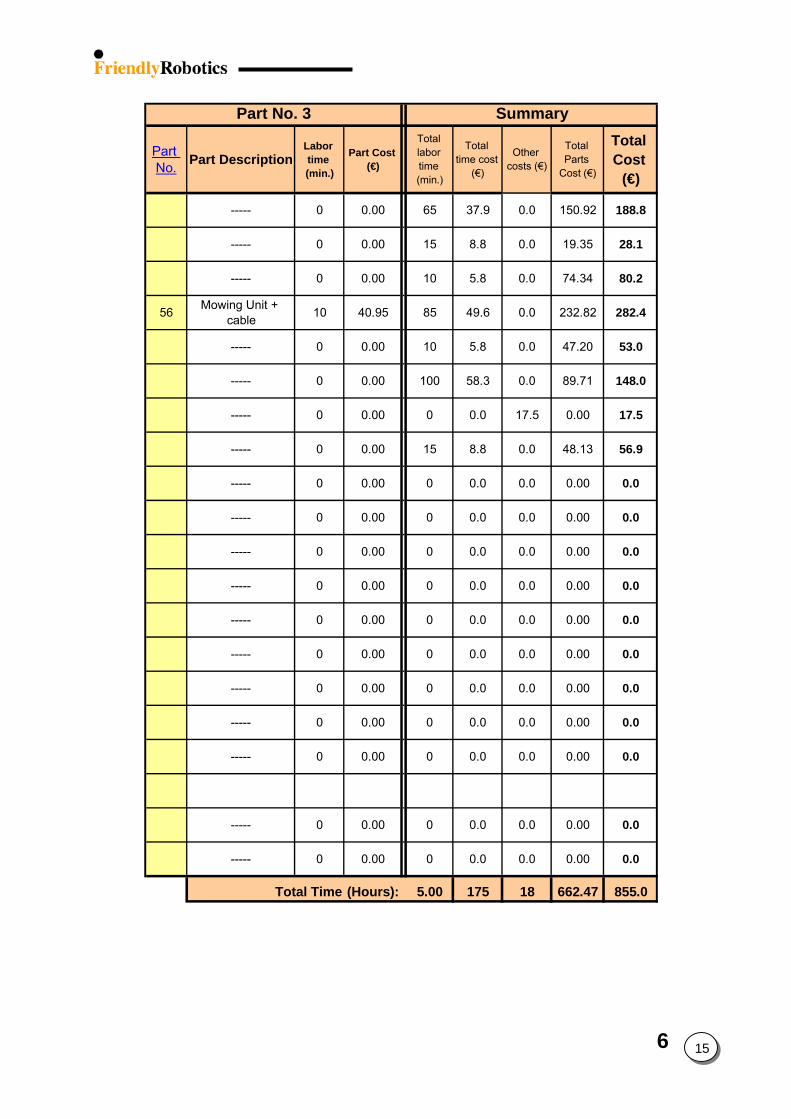
6 15
Part No. Part Description
Labor time (min.)
Part Cost (€)
Total labor time (min.)
Total time cost
(€)
Other costs (€)
Total Parts
Cost (€)
Total Cost
(€)
----- 0 0.00 65 37.9 0.0 150.92 188.8
----- 0 0.00 15 8.8 0.0 19.35 28.1
----- 0 0.00 10 5.8 0.0 74.34 80.2
56 Mowing Unit + cable 10 40.95 85 49.6 0.0 232.82 282.4
----- 0 0.00 10 5.8 0.0 47.20 53.0
----- 0 0.00 100 58.3 0.0 89.71 148.0
----- 0 0.00 0 0.0 17.5 0.00 17.5
----- 0 0.00 15 8.8 0.0 48.13 56.9
----- 0 0.00 0 0.0 0.0 0.00 0.0
----- 0 0.00 0 0.0 0.0 0.00 0.0
----- 0 0.00 0 0.0 0.0 0.00 0.0
----- 0 0.00 0 0.0 0.0 0.00 0.0
----- 0 0.00 0 0.0 0.0 0.00 0.0
----- 0 0.00 0 0.0 0.0 0.00 0.0
----- 0 0.00 0 0.0 0.0 0.00 0.0
----- 0 0.00 0 0.0 0.0 0.00 0.0
----- 0 0.00 0 0.0 0.0 0.00 0.0
----- 0 0.00 0 0.0 0.0 0.00 0.0
----- 0 0.00 0 0.0 0.0 0.00 0.0
5.00 175 18 662.47 855.0Total Time (Hours):
Part No. 3 Summary
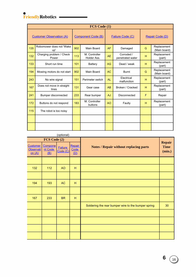
6 16
135 Robomower does not 'Wake up' 902 Main Board AF Damaged G Replacement
(Main board)
132 Charging problem / Check Power 113 M. Controller
Holder Ass. AE Corroded / penetrated water H Replacement
(part)
133 Short run time 101 Battery AG Dead / weak H Replacement (part)
194 Mowing motors do not start 902 Main Board AC Burnt G Replacement (Main board)
243 No wire signal 151 Perimeter switch AL Electrical malfunction H Replacement
(part)
167 Does not move in straight lines 131 Gear case AB Broken / Cracked H Replacement
(part)
241 Bumper disconnected 233 Rear bumper AJ Disconnected F Repair
172 Buttons do not respond 183 M. Controller buttons AO Faulty H Replacement
(part)
115 The robot is too noisy
FCS Code (1)
Component Code (B) Failure Code (C)Customer Observation (A) Repair Code (D)
(optional)
Customer Observati
on (A)
Component Code
(B)
Failure Code (C)
Repair Code
(D)
132 112 AO H
193 AC H
233 BR H
Soldering the rear bumper wire to the bumper spring 30
Notes / Repair without replacing partsRepair Time (min.)
FCS Code (2)
194
167
Appendix B – Claimed Time
The time claimed is the time required to repair the unit. This time includes the diagnostics time needed to identify the problem, the Test time (see chapter 5.1 in the Service Guide) that should be performed after any service routine was performed on the unit and the repair time required to replace/repair the faulty part by the service/dealer. The following formula describes the total time claimed calculation: The Ti& Cost
Below
Diaave
RepWhmin
Tesave
Cl
If ithe
Exam The cuDuringWhenfrom twhichIn tota
Diagnostics Time + Repair Time + Test Time = Time Claimed
6 17
me Claimed should be taken from the table shown in appendix 1 – the second spreadsheet ‘Parts List & Time’ in the excel file (‘Warranty claim form 2004).
are some clarifications for the table (appendix 1) and the time claimed calculation:
gnostics time is divided into three different time levels, 5, 10 and 15 minutes, based on an rage time required to identify a problem before starting any repair activity on the unit.
air Time should be taken from the table in appendix 1 in this document. en calculating the total repair time for internal procedures, where the cover is removed, 20 utes are added to cover the time of the removing and returning the cover.
t Time is divided into three different time levels, 5, 10 and 15 minutes, based on an rage time required to test the unit after the problem was fixed.
Total time claimed (part 1) + Repair Time (part 2) = Total Time Claimed
aim with more than one faulty parts inside the mower t is required to replace more than one part during internal repair, where the cover is removed, claimed time should be calculated as following:
ple
stomer is complaining about faulty mowing system. the service it was found that the Main Board and one of the mowing units are faulty.
calculating the claimed time, take the ‘Total claimed time’ of part number 1 (Main Board) he table, which is 60 minutes and add the repair time of part number 2 (Mowing unit), is 10 minutes. l the claimed time for the above claim is 70 minutes (60+10).
6 18
6.2 Robomow Power Pack Charging Policy
6.2.1 Overview
A battery is an integral part of the electrical system for most motorcycles, snowmobiles,
ATV's and watercraft. Even so, batteries often receive less care than they deserve. And improper care can lead to
shortened battery life. Lead acid batteries are used as a power source for the Robomower that demands a constant
and uninterruptible source of energy. The Robomower needs energy to operate the drive motors, the mowing system, the Main board, and other battery-drive accessories such as the LCD display and audio.
Glossary - Ampere - The unit for measuring the flow of electric current. - Ampere-hour (Ah) – The current in (A amperes) multiplied by time in (h hours). Used to
indicate the capacity of a battery. - Capacity (C) – Ampere-hours that can be discharged from a battery. - Cell – the minimum unit, which a battery is composed of, consisting of positive and
negative plates, separators, electrolyte, etc. - Charging – the process of storing electrical energy in a battery in a chemical form. - Cycle Service – The use of a battery with alternate repetition of charging and discharging.
The battery cycles are measured to the point where the battery looses 20% of its initial capacity.
- Cycle Service Life – The total number of cycles expected at a given depth of discharge. - Discharge – The process of drawing stored energy out of a battery in the form of electrical
power. - Depth of discharge (D.O.D) – The ratio of discharge capacity vs. the rated capacity of a
battery. - Life Expectancy – Expected service life of a battery expressed in total cycles. - Self-Discharge – Loss of capacity without external current drain. - Shelf Life – The maximum period of time a battery can be stored, under specified
conditions, without needing supplementary charging.
Battery Specification
• Power Pack – 2 x 17 AH, 12V sealed lead acid • Battery Model – NP17-12 • Cycle Service Life – 200-300 discharge/recharge cycles • Weight - ~13KG • Maintenance-free
6 19
Power Supply
The Robomower uses an external power supply to provide the required energy for charging while an on board computer controls the actual battery charging process.
The Power Supply is manufacturing by Eng. ELECTRIC Co. LTD Friendly Robotics uses two power supply models: A – Input: 120VAC 60 Hz 38 W
Output: 32VDC 900mA This model is UL approved
B – Input: 230VAC 50 Hz 40 W Output: 31VDC 900mA This model is CE approved
6.2.2 Charging procedure
The charging cycle is divided into 3 stages* as follows: Stage 1: The Input voltage is maximal. The time it takes to reach this voltage (T1) is recorded and will be used at later stage. If T1 < 5 minutes and battery voltage is higher than 28V, we will skip stage 2 and move to the Floating stage. If T1 >= 5 minutes and battery voltage is higher than 29.4V, we will move to stage 2. Stage 2: The voltage controller keeps the Input voltage at 29.4V. The charging process will proceeds to the Floating stage after T1/2 hours if T > 6 hours or after 6 hours if T1 <= 6 hours Stage 4 (Floating): The voltage controller keeps the Input voltage at “floating” voltage of 27.2V and stays as is until charging process is terminated.
Top Charging
Top Charging is a recommended process to be applied to any battery, which has been stored
for a long period of time, since the battery loses capacity through self-discharge.
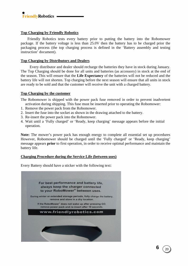
6 20
Top Charging by Friendly RoboticsFriendly Robotics tests every battery prior to putting the battery into the Robomower
package. If the battery voltage is less than 25.0V then the battery has to be charged prior the packaging process (the top charging process is defined in the ‘Battery assembly and testing instruction’ document).
Top Charging by Distributors and Dealers
Every distributor and dealer should recharge the batteries they have in stock during January. The Top Charging should be done for all units and batteries (as accessory) in stock at the end of the season. This will ensure that the Life Expectancy of the batteries will not be reduced and the battery life will not shorten. Top charging before the next season will ensure that all units in stock are ready to be sold and that the customer will receive the unit with a charged battery. Top Charging by the customerThe Robomower is shipped with the power pack fuse removed in order to prevent inadvertent
activation during shipping. This fuse must be inserted prior to operating the Robomower: 1. Remove the power pack from the Robomower. 2. Insert the fuse into the socket as shown in the drawing attached to the battery. 3. Re-insert the power pack into the Robomower. 4. Wait until a ‘Fully charged’ or ‘Ready, keep charging’ message appears before the initial
operation. Note: The mower’s power pack has enough energy to complete all essential set up procedures However, Robomower should be charged until the ‘Fully charged’ or ‘Ready, keep charging’ message appears prior to first operation, in order to receive optimal performance and maintain the battery life.
Charging Procedure during the Service Life (between uses)
Every Battery should have a sticker with the following text:
6 21
1. Make sure the charger is plugged into a standard 110V or 220V household outlet. 2. Connect the charging plug to the Robomower at the manual controller base. 3. Pivot it up on its hinges, connect the charger plug and pivot it back to lie flush with the
surface. 4. The display will read “Charging…”. The display will read “Fully Charged” or “Ready,
keep charging” when ready for operation. 5. The charger is for indoor use only, on dry surface. Never charge in areas where water
is a potential hazard. 6. The Robomower should be charging at all times when not in use. Continuous charging
does not harm the batteries.
Note: The mower will alert when battery voltage is low (below the voltage level, which the ‘Recharge battery’ message had been displayed). In such a case an immediate charging is required.
Cautions:
(1) Operating the Robomower prior to having a ‘Fully charged’ or ‘Ready, keep charging’ message will reduce the battery life. (2) Leaving the Robomower without charging after the ‘Recharge battery’ message is received will cause a deep discharge, which will reduce the battery life and capacity. In such a case the battery will dry in several days.
(3) Leaving the Robomower without charging after the ‘Fully charged’ or ‘Ready, keep charging’ message is received will cause the battery to dry in 6-10 weeks.
Winterizing charging procedure
The following procedure is recommended for extended storage periods, during the winter and for those households where the Robomower is stored in a geographic location where regular winter temperatures often drop below freezing:
1. Charge the battery until a ‘Fully Charged’ or ‘Ready, keep charging’ message is displayed.
2. Remove the battery and store outside the mower in a cool dry environment. 3. Repeat this process every 3 months. 4. If temperatures should drop below -20ºC (-4ºF), follows steps 1 through 3, and store the
battery in a warmer place. 5. The Robomower should be charged at temperatures lower than 60ºC (140ºF) and higher
than 0ºC (32ºF). Exceeding these conditions will cause a ‘High/Low temp – disconnect charger’ message to be displayed, until the temperatures return to the safe charging range.
6. Do not store or charge the Robomow with items pressing against the bumpers. Do not store or charge the Robomower if it is positioned on its bumpers.
6 22
Note: Mower has “Auto shutdown” after 20 minutes – if the mower is not in operation or charging for 15 minutes it will shut down automatically. In such case, the mower consumes about 10mA during the ‘sleep’. This is why we recommend removing the battery out of the mower during long storage periods if the charging process cannot be guaranteed.
6.2.3 Storage and shelf life
Storage between uses The battery should always be kept in charging between uses during the mowing season. It can be done by using the power supply through the Robomower when the battery is placed inside the Robomower or by an external charger when the battery is outside the Robomower.
Storage for a long period During winter or extended storage periods, fully charge the battery, remove and store in a dry location. Or keep the charger connected during this period (see winterizing charging procedure).
6.2.4 Closure
Failures handling See section 3.2.2 in the Service Guide
Battery warranty The battery warranty given by Friendly Robotics is valid when following this charging procedure. Any case in which the customer did not follow this procedure, Friendly will not accept the claim.
7. Service Bulletins
Service Bulletins are special additional instructions to be followed when servicing or
replacing a specific part or parts of the Robomower. Some may be relevant for specific models or serial number range. Such cases will be specified at the top part of each bulletin.
For the dealer’s convenience, most of the Service Bulletins are printed and attached to the spare parts supplied by Friendly Robotics.
Once again, the Service Bulletins are in addition to the repair instructions of the Service Guide. Carefully read the Service Bulletin and the relevant procedure in chapter 4 in the Service Guide before replacing/assembling any part.
7. Service Bulletins - Contents
7.1 Main Board #RL0536-01 ………………………….…….7.2
7.2 Gear Case #RL0536-02 ………………………………….7.3
7.3 Wire Sensors #RL0536-03 ………………………...…….7.5
7.4 RL Cover #RL0536-04 ………………………….……….7.6
7.5 Front Wheel spring/stopper #RL0536-05 …………....….7.7
7.6 Mowing Unit #RL0536-06 …………………………...….7.8
7.7 Charging #RL0320-07 …………………………..........….7.9
7.8 Front Bumper #RL0340-08 ……………..……………….7.10
7.9 Manual Controller #RL0536-09 …………..……………..7.11
7.10 Thermistors Kit #RL0340-10 ………………….……….7.12
7.11 S.W versions #RL0536-11 ……………………….…….7.13
7
1
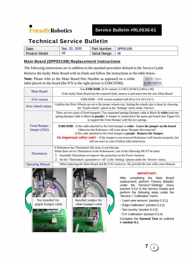
Service Bulletin #RL0536-01
Technical Service Bulletin Date: Sep. 20, 2005 Part Number: SPP0019B Product Model: All Serial Range: All
Main Board (SPP0019B) Replacement Instructions The following instructions are in addition to the standard procedure defined in the Service Guide. Remove the faulty Main Board with its Flash and follow the instructions in the table below. Note: Please refer to the Main Board Part Number as appeared on a white label placed on the board (the P/N in the right picture is ESBC050B).
Main Board Use ESBC050B (S.W version 2.5-06/3.19-06/3.2-06/4.1-06)
If the faulty Main Board has the required flash, remove it and insert into the new Main Board
S.W version ESBC050B – S/W version marked with 06 (2.5/3.19/3.2/4.1)
Drive wheels setting Confirm the Drive Wheels are set to the proper wheels size. Setting the wheels size is done by choosing the ‘Small wheels’ option in the ‘Settings’ menu under ‘Service’.
There are two types of front bumpers: Two separated springs (bumper cable is Black & white) and one spring (bumper cable is Black & purple). A Jumper is connected to the spare part board (See Figure 01)
to support the Front Bumper with the two springs.
Front Bumper Jumper (J502)
ESBC050B – If the cable attached to the front bumper is white - Leave the jumper on the board Otherwise the Robomow will warn about ‘Bumper disconnected’
- If the cable attached to the front bumper is purple - Remove the Jumper. An important safety note! - If the Jumper is not removed Robomow will function properly, but
will not warn in case of failure (disconnection).
Thermistors
If Robomow has Thermistors this issue is not relevant. When there are no Thermistors in the Robomower, one of the following MUST be done: 1. Assemble Thermistors to improve the protection on the Power Systems. 2. Set the ‘Thermistors’ parameter to ‘off’ in the ‘Setting’ options under the ‘Service’ menu.
Operating Manual When replacing the Main Board and the S.W version to ‘06, provide the user with a new Manual
Installed jumper for white bumper cable
Not installed for purple bumper cable
Installed jumper for white bumper cable
Not installed for purple bumper cable
IMPORTANT! After completing the Main Board replacement, perform ‘Factory defaults’ under the ‘Service’>’Settings’ menu (section 5.5.6 in the Service Guide) and perform the following steps under the ‘Service’> ’Calibration’ menu: - ‘Learn wire sensors’ (section 5.3.1) - ‘Edge Calibration’ (section 5.3.2) - ‘Set country’ (section 5.3.3) - ‘D.K Calibration’ (section 5.3.4) Complete the General Test as outlined in section 5.1.
7 2
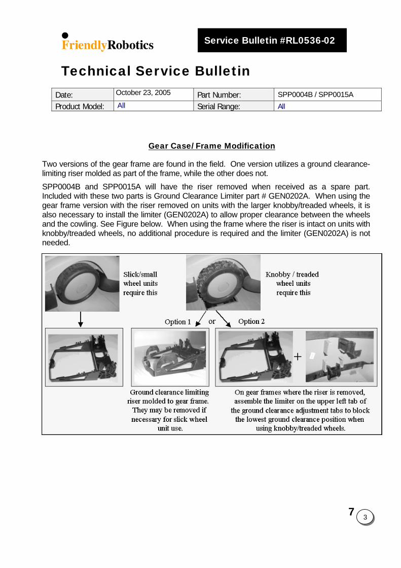
7
3
Service Bulletin #RL0536-02
Technical Service Bulletin Date: October 23, 2005 Part Number: SPP0004B / SPP0015A Product Model: All Serial Range: All
Gear Case/ Frame Modification
Two versions of the gear frame are found in the field. One version utilizes a ground clearance-limiting riser molded as part of the frame, while the other does not. SPP0004B and SPP0015A will have the riser removed when received as a spare part. Included with these two parts is Ground Clearance Limiter part # GEN0202A. When using the gear frame version with the riser removed on units with the larger knobby/treaded wheels, it is also necessary to install the limiter (GEN0202A) to allow proper clearance between the wheels and the cowling. See Figure below. When using the frame where the riser is intact on units with knobby/treaded wheels, no additional procedure is required and the limiter (GEN0202A) is not needed.
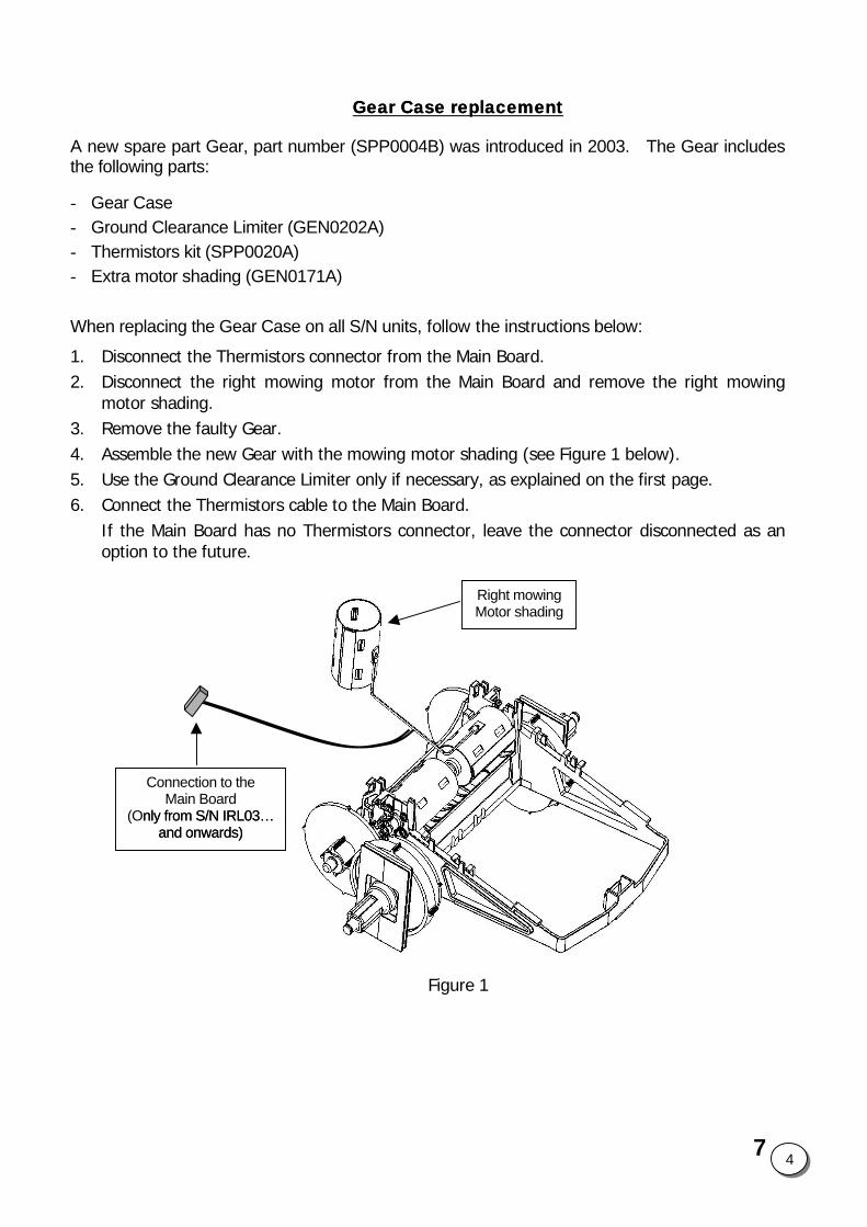
Gear Case replacementGear Case replacement
A new spare part Gear, part number (SPP0004B) was introduced in 2003. The Gear includes the following parts:
- Gear Case - Ground Clearance Limiter (GEN0202A) - Thermistors kit (SPP0020A) - Extra motor shading (GEN0171A)
When replacing the Gear Case on all S/N units, follow the instructions below:
1. Disconnect the Thermistors connector from the Main Board. 2. Disconnect the right mowing motor from the Main Board and remove the right mowing
motor shading. 3. Remove the faulty Gear. 4. Assemble the new Gear with the mowing motor shading (see Figure 1 below). 5. Use the Ground Clearance Limiter only if necessary, as explained on the first page.
Right mowingMotor shading
Connection to the Main Board
( nly from S/N IRL03… and onwards)
nly from S/N IRL03… and onwards)
O
6. Connect the Thermistors cable to the Main Board. If the Main Board has no Thermistors connector, leave the connector disconnected as an option to the future.
Figure 1
7 4
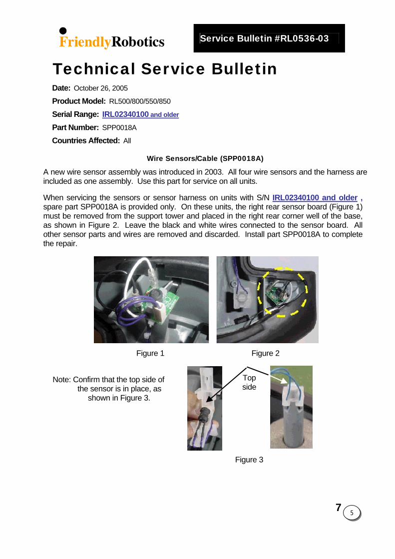
Service Bulletin #RL0536-03
Technical Service Bulletin Date: October 26, 2005
Product Model: RL500/800/550/850
Serial Range: IRL02340100 and older
Part Number: SPP0018A
Countries Affected: All
Wire Sensors/Cable (SPP0018A)
A new wire sensor assembly was introduced in 2003. All four wire sensors and the harness are included as one assembly. Use this part for service on all units.
When servicing the sensors or sensor harness on units with S/N IRL02340100 and older , spare part SPP0018A is provided only. On these units, the right rear sensor board (Figure 1) must be removed from the support tower and placed in the right rear corner well of the base, as shown in Figure 2. Leave the black and white wires connected to the sensor board. All other sensor parts and wires are removed and discarded. Install part SPP0018A to complete the repair.
Figure 1 Figure 2
Top side
Note: Confirm that the top side of the sensor is in place, as shown in Figure 3. Figure 3
7
5
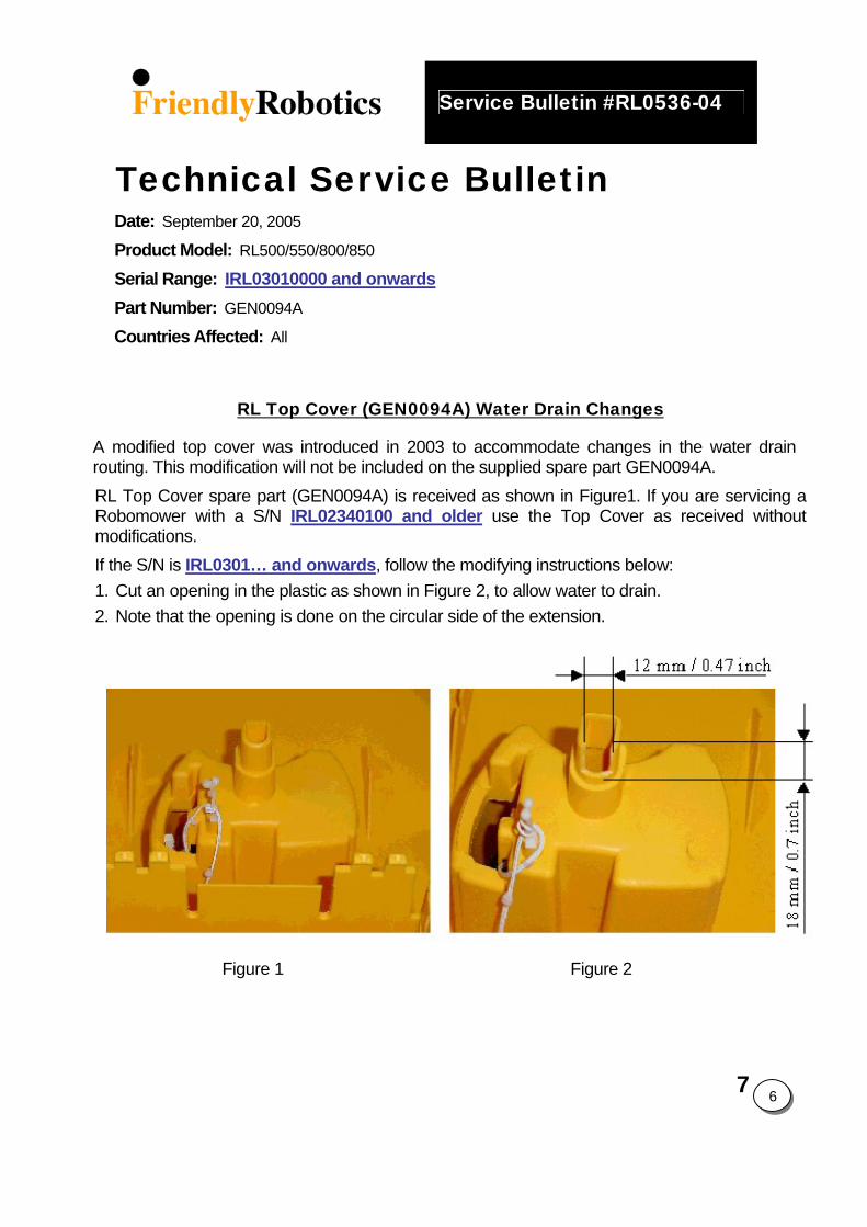
7
6
Service Bulletin #RL0536-04
Technical Service Bulletin Date: September 20, 2005
Product Model: RL500/550/800/850
Serial Range: IRL03010000 and onwardsPart Number: GEN0094A
Countries Affected: All
RL Top Cover (GEN0094A) Water Drain Changes
A modified top cover was introduced in 2003 to accommodate changes in the water drain routing. This modification will not be included on the supplied spare part GEN0094A. RL Top Cover spare part (GEN0094A) is received as shown in Figure1. If you are servicing a Robomower with a S/N IRL02340100 and older use the Top Cover as received without modifications. If the S/N is IRL0301… and onwards, follow the modifying instructions below: 1. Cut an opening in the plastic as shown in Figure 2, to allow water to drain. 2. Note that the opening is done on the circular side of the extension.
Figure 1 Figure 2
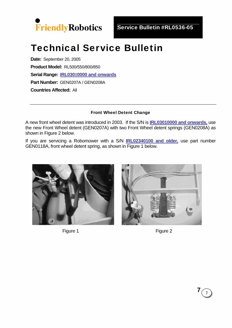
7
7
Service Bulletin #RL0536-05
Technical Service Bulletin Date: September 20, 2005
Product Model: RL500/550/800/850
Serial Range: IRL03010000 and onwardsPart Number: GEN0207A / GEN0208A
Countries Affected: All
Front Wheel Detent Change
A new front wheel detent was introduced in 2003. If the S/N is IRL03010000 and onwards, use the new Front Wheel detent (GEN0207A) with two Front Wheel detent springs (GEN0208A) as shown in Figure 2 below. If you are servicing a Robomower with a S/N IRL02340100 and older, use part number GEN0118A, front wheel detent spring, as shown in Figure 1 below.
Figure 1 Figure 2
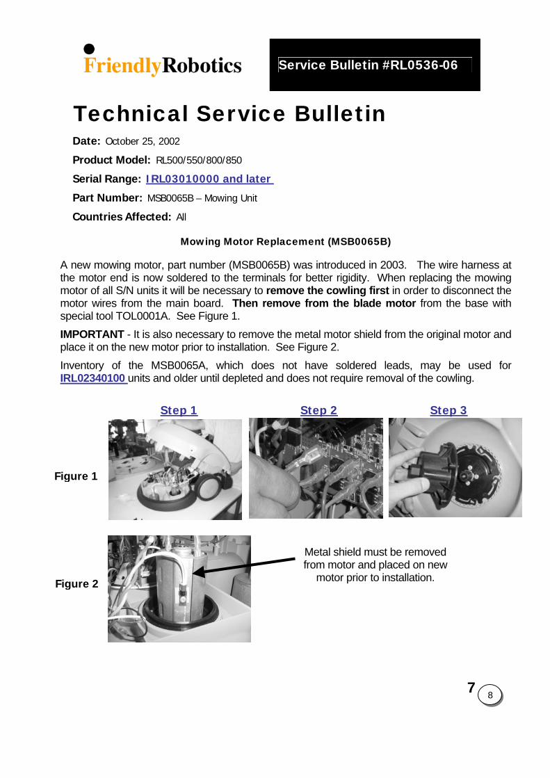
7
8
Service Bulletin #RL0536-06
Technical Service Bulletin Date: October 25, 2002
Product Model: RL500/550/800/850
Serial Range: IRL03010000 and later
Part Number: MSB0065B – Mowing Unit
Countries Affected: All
Mowing Motor Replacement (MSB0065B)
A new mowing motor, part number (MSB0065B) was introduced in 2003. The wire harness at the motor end is now soldered to the terminals for better rigidity. When replacing the mowing motor of all S/N units it will be necessary to remove the cowling first in order to disconnect the motor wires from the main board. Then remove from the blade motor from the base with special tool TOL0001A. See Figure 1. IMPORTANT - It is also necessary to remove the metal motor shield from the original motor and place it on the new motor prior to installation. See Figure 2. Inventory of the MSB0065A, which does not have soldered leads, may be used for IRL02340100 units and older until depleted and does not require removal of the cowling.
Step 1 Step 2 Step 3
Figure 1
Metal shield must be removed from motor and placed on new
motor prior to installation. Figure 2
7
9
Service Bulletin #RL0305-07
Technical Service Bulletin Date: June 04, 2003
Product Model: RL550/800/850
Serial Range: Beginning IRL03…
Part Number: Robomower
Countries Affected: All
2003 RL550/RL800/RL850 Operating Manual Addendum
The 2003 Owner’s Operating Manual indicates that a text message, ‘Ready- Keep Charging’ will appear on the LCD screen of the manual controller when the Power Pack is fully charged and ready for use. This typically occurs in approximately 24 hours, depending on state of charge when connected to the Robomower. Please note that in some circumstances, the ‘Ready-Keep Charging’ message may not appear in this time frame, and may in fact not appear for a number of hours later. The message, ‘Charging’, will continue to display. However, at the 24-26 hour time frame the Power Pack is fully charged and ready to be used even if the ‘Ready-Keep Charging’ message does not display. The message of ‘Ready-Keep Charging’ a result of various factors in the charging process, but has little impact from the current voltage level of the Power Pack. A variety of issues can delay the display of the message, such as ambient temperature and voltage output from the home receptacle. In any event, after approximately 24 hours of charging in the Robomower, the Power Pack is fully charged and ready to be used.
If the message of ‘Ready-Keep Charging’ is not displayed at all and ‘Charging Failure’ message is intermittently displayed while the mower is in charging, the S/W version of this Robomower should be replaced with an updated version (P/N PRG0005A - 3.2i - Apr 29, 2003). Call Friendly Customer Support to receive the most updated S.W. version.
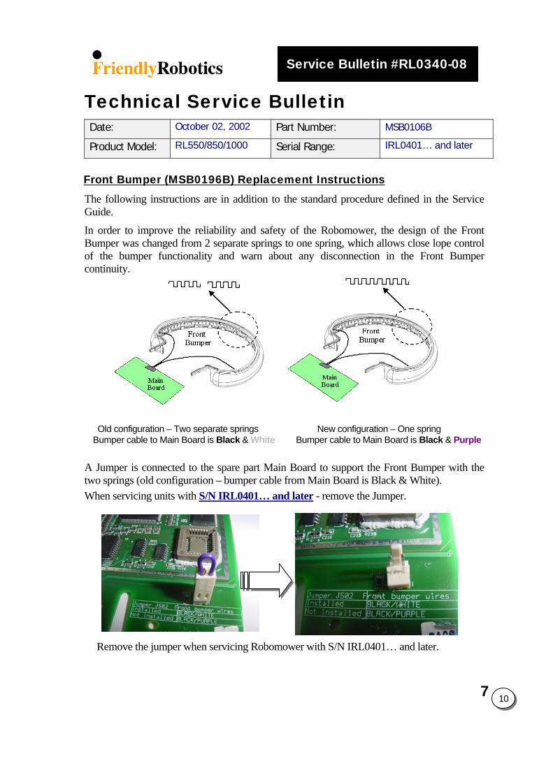
7
10
Service Bulletin #RL0340-08
Technical Service Bulletin Date: October 02, 2002 Part Number: MSB0106B
Product Model: RL550/850/1000 Serial Range: IRL0401… and later
Front Bumper (MSB0196B) Replacement Instructions The following instructions are in addition to the standard procedure defined in the Service Guide.
In order to improve the reliability and safety of the Robomower, the design of the Front Bumper was changed from 2 separate springs to one spring, which allows close lope control of the bumper functionality and warn about any disconnection in the Front Bumper continuity.
Old configuration – Two separate springs New configuration – One spring Bumper cable to Main Board is Black & White Bumper cable to Main Board is Black & Purple
A Jumper is connected to the spare part Main Board to support the Front Bumper with the two springs (old configuration – bumper cable from Main Board is Black & White). When servicing units with S/N IRL0401… and later - remove the Jumper.
Remove the jumper when servicing Robomower with S/N IRL0401… and later.
Service Bulletin #RL0536-09
Technical Service Bulletin Date: Oct 26, 2005 Part Number: MSB0117A
Product Model: RL350/550/800/850/1000 Countries Affected: All
S.W version: All
Manual Controller (MSB0117A) Replacement Instructions The following instructions are in addition to the standard procedure defined in the Service Guide. Three Manual Controllers spare part are available in 2006 season: 1. P/N MSB0118A (Extended temperature range LCD – Green color LCD)
P/N MSB0119A (Enhanced Manual Controller + Rain sensor) 2. Old versions:
P/N MSB0112A (tones) P/N MSB0114A (speech- used in the US)
When servicing Robomow with S.W versions 3.19-04 / 3.2-04 / 4.1-04 and later use Manual Controller P/N MSB0117A/18/19 to all Robomow models (RL350/550/800/850/1000). When servicing Robomower with S.W versions previous to those mentioned above*, all configurations of Manual Controllers can be used, but it is recommended to replace the same part number for the user’s convenience, keeping the speech or tones features. * Previous S.W versions are versions released before Aug 01, 2003 (The S.W version date is displayed as ‘S.W version’ menu under the ‘Service’ or the ‘Information’ menus).
7
11
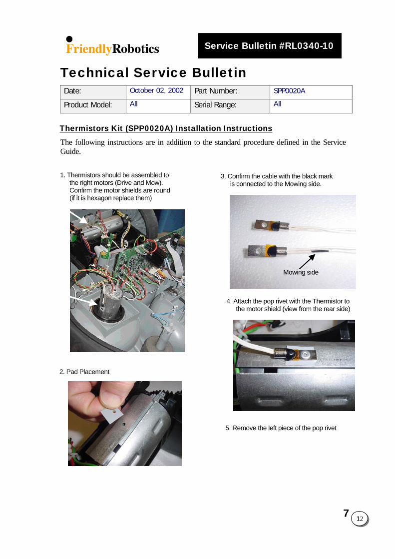
Service Bulletin #RL0340-10
Technical Service Bulletin Date: October 02, 2002 Part Number: SPP0020A
Product Model: All Serial Range: All
Thermistors Kit (SPP0020A) Installation Instructions The following instructions are in addition to the standard procedure defined in the Service Guide.
1. Thermistors should be assembled tothe right motors (Drive and Mow). Confirm the motor shields are round (if it is hexagon replace them)2. Pad Placement
3. Confirm the cable with the black markis connected to the Mowing side.
Mowing side
4. Attach the pop rivet with the Thermistor to the motor shield (view from the rear side)
5. Remove the left piece of the pop rivet7 12
Service Bulletin #RL0536-11
Technical Service Bulletin Date: Sep 20, 2005 Part Numbers: All Software Version
Product Model: All Countries Affected: All
Serial Range: All
S.W. version (Flash) Replacement Instructions The following instructions are in addition to the standard procedure defined in the Service Guide.
Spare Part Flash
(S.W. version) When to use? Main Board Manual
Controller
SPP0033C/35C/ 36C/40C/41C
3.2-06
The most updated S.W version for
RL850 - compatible with Main Board ESBC050B
SPP0019B Main Board label
is marked with ESBC050B
All
SPP0101A-105A 4.1-06
The most updated S.W version for
RL1000 - compatible with Main Board ESBC050B
SPP0019B Main Board label
is marked with ESBC050B
All
SPP0027A 3.2a
The most updated S.W version compatible with Main Board
ESB0019B/C.
Main Board label is marked with ESB0019B/C
MSB0112A MSB0114A
(Does not support MSB0117A to MSB0019A)
PRG0005A 3.2i
(Service Bulletin
#RL0305-07)
Service version supporting Main Board ESBC045B only (especially for
‘Charging failure’ message received during the charging process)
Main Board label is marked with
ESBC045B
MSB0112A MSB0114A
(Does not support MSB0117A to MSB0019A)
NOTE: After replacing a flash (S.W version) it is required to perform the following steps:
1. 'Factory defaults' under the 'Service>Settings' menu. 2. The mower will display 'Are you sure?’ - Press the ‘GO’ button to confirm (it will reset). 3. Under 'Service' perform 'Learn wire sensors' (Section 5.3.4 in the Service Guide) 4. Under 'Service' perform 'Edge Calibration' (Section 5.3.3 in the Service Guide) 5. Under 'Service' perform ‘Set country' (Section 5.3.1 in the Service Guide). 6. Under 'Service' perform ‘DK Calibration’ (Section 5.3.2 in the Service Guide).
7 13
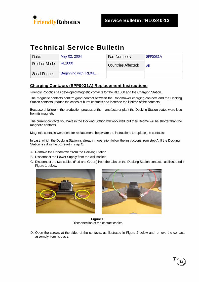
7 13
Service Bulletin #RL0340-12
Technical Service Bulletin Date: May 02, 2004 Part Numbers: SPP0031A
Product Model: RL1000 Countries Affected: All
Serial Range: Beginning with IRL04…
Charging Contacts (SPP0031A) Replacement Instructions Friendly Robotics has developed magnetic contacts for the RL1000 and the Charging Station.
The magnetic contacts confirm good contact between the Robomower charging contacts and the Docking Station contacts, reduce the cases of burnt contacts and increase the lifetime of the contacts. Because of failure in the production process at the manufacturer plant the Docking Station plates were lose from its magnetic The current contacts you have in the Docking Station will work well, but their lifetime will be shorter than the magnetic contacts. Magnetic contacts were sent for replacement, below are the instructions to replace the contacts: In case, which the Docking Station is already in operation follow the instructions from step A. If the Docking Station is still in the box start in step C: A. Remove the Robomower from the Docking Station. B. Disconnect the Power Supply from the wall socket. C. Disconnect the two cables (Red and Green) from the tabs on the Docking Station contacts, as illustrated in
Figure 1 below.
Figure 1 Disconnection of the contact cables D. Open the screws at the sides of the contacts, as illustrated in Figure 2 below and remove the contacts
assembly from its place.
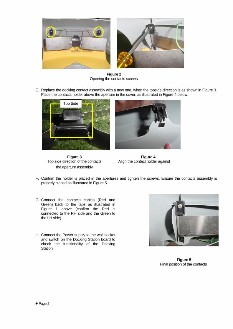
Figure 2 Opening the contacts screws E. Replace the docking contact assembly with a new one, when the topside direction is as shown in Figure 3.
Place the contacts holder above the aperture in the cover, as illustrated in Figure 4 below.
Top Side
Figure 3 Figure 4 Top side direction of the contacts Align the contact holder against the aperture assembly F. Confirm the holder is placed in the apertures and tighten the screws. Ensure the contacts assembly is
properly placed as illustrated in Figure 5. G. Connect the contacts cables (Red and
Green) back to the taps as illustrated in Figure 1 above (confirm the Red is connected to the RH side and the Green to the LH side).
H. Connect the Power supply to the wall socket
and switch on the Docking Station board to check the functionality of the Docking Station.
Figure 5 Final position of the contacts
Page 2