robinson section 9 ii supplementsfloats, additional airframe sealing and corrosion protection,...
TRANSCRIPT

FAA APPROVED: 17 DEC 2019 9-i
ROBINSON MODEL R44 II
SECTION 9SUPPLEMENTS
SECTION 9
SUPPLEMENTS
OPTIONAL EQUIPMENT SUPPLEMENTS
Information contained in the following supplements applies only when the related equipment is installed.
CONTENTSPage
Fixed Floats . . . . . . . . . . . . . . . . . . . . . . . 9-5.1
Heated Pitot . . . . . . . . . . . . . . . . . . . . . . . 9-6.1
Police Version . . . . . . . . . . . . . . . . . . . . . . 9-7.1
ENG Version . . . . . . . . . . . . . . . . . . . . . . . 9-8.1
Garmin GPSMAP 225 . . . . . . . . . . . . . . . . 9-9.1
Pop-Out Floats . . . . . . . . . . . . . . . . . . . . . 9-10.1
Air Conditioning . . . . . . . . . . . . . . . . . . . . 9-11.1
ADS-B Equipment . . . . . . . . . . . . . . . . . . . 9-12.1
HeliSAS Autopilot . . . . . . . . . . . . . . . . . . . 9-13.1
Optional Avionics . . . . . . . . . . . . . . . . . . . 9-14.1
NON-U.S. SUPPLEMENTS
The following supplements contain additional information required by certain countries:
Brazilian Supplement
Canadian Supplement
EASA Supplement
FATA Supplement (Russia)
IAC AR Supplement
Indian Supplement
Ukranian Supplement

INTENTIONALLY BLANK

ROBINSON MODEL R44 II
SECTION 9FIXED FLOATS SUPPLEMENT
FAA APPROVEDR44 II PILOT’S OPERATING HANDBOOK
FIXED FLOATS SUPPLEMENT
This supplement must be included in the FAA-approved Pilot’s Operating Handbook when fixed-float landing gear is installed.
Information contained herein supplements or supersedes the .tnemelppus siht ni detsil saera esoht ni ylno launam cisab
For limitations, procedures, and performance information not contained in this supplement, consult the basic Pilot’s Operating Handbook.
APPROVED BY:Manager, Flight Test Branch, ANM-160LFederal Aviation Administration, LAACOTransport Airplane Directorate
DATE:
LOG OF REVISIONS
PageNo. Date
9-5.19-5.29-5.39-5.49-5.59-5.69-5.7
17 Dec 1917 Dec 1917 Dec 193 Oct 02
17 Dec 1917 Dec 193 Oct 02
PageNo. Date
9-5.89-5.99-5.109-5.119-5.129-5.13
17 Dec 1917 Dec 193 Oct 02
17 Dec 1917 Dec 193 Oct 02
9-5.1
REVISIONSAPPROVED BY:
Manager, West Flight Test Section, AIR-716Federal Aviation AdministrationLos Angeles, CA
DATE: 17 DEC 2019

FAA APPROVED: 17 DEC 2019 9-5.2
SECTION 1: GENERAL
INTRODUCTION
This supplement contains the changes and additional data applicable when fixed-float landing gear is installed.
Float landing gear is intended for safety during flights over water. Intentional (non-emergency) water landings for other than training purposes are not recommended.
NOTE
The float landing gear is approved for amphibious operation but is not certified for ditching. Some countries may prohibit certain over-water operations.
SECTION 2: LIMITATIONS
AIRSPEED LIMITATIONS
NEVER EXCEED AIRSPEED (Vne) WITH FLOATS
2200 lb TOGW & below 120 KIASOver 2200 lb TOGW 110 KIASAutorotation 100 KIAS
For Vne reductions with altitude and temperature, see placards on page 9-5.3.
FLIGHT AND MANEUVER LIMITATIONS
Water landings for any reason other than an actual emergency are prohibited at weights above 2400 lb.
ROBINSON MODEL R44 II
SECTION 9FIXED FLOATS SUPPLEMENT

ROBINSON MODEL R44 II
SECTION 9FIXED FLOATS SUPPLEMENT
SECTION 2: LIMITATIONS (cont’d)
PLACARDS
In clear view and readable by the pilot in flight:
FAA APPROVED: 17 DEC 2019 9-5.3

ROBINSON MODEL R44 II
SECTION 9FIXED FLOATS SUPPLEMENT
SECTION 2: LIMITATIONS (cont’d)
FLOAT PRESSURE LIMITS
Minimum Float Pressure: 1.5 psig (psi gage)Maximum Float Pressure: 5 psig
A decrease in altitude or temperature reduces float pressure. If decrease in altitude or temperature is anticipated, inflate floats per chart below to ensure 1.5 psig minimum at landing. Pressure relief valves will limit pressure for an increase in altitude or temperature.
EXAMPLE: PressureAltitude Temp
Conditions at destination:Initial conditions:Subtract to obtain change
in altitude and temp:
1000 ft5500 ft
15°C5°C
–4500 ft +10°C
Using graph, locate –4500 ft line, read across to +10°C line, then down for minimum initial float pressure required, approximately 3.2 psig.
FAA APPROVED: 3 OCT 2002 9-5.4

ROBINSON MODEL R44 II
SECTION 9FIXED FLOATS SUPPLEMENT
FAA APPROVED: 17 DEC 2019 9-5.5
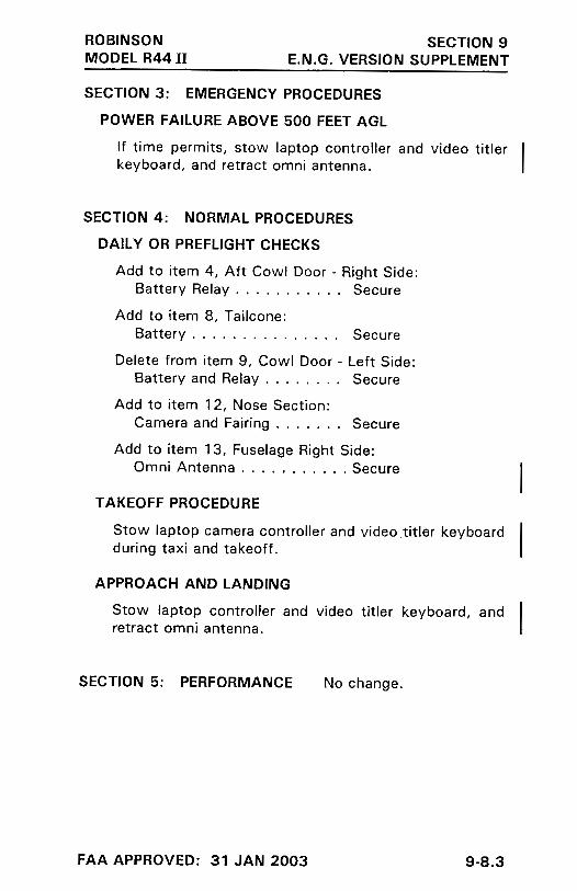
SECTION 3: EMERGENCY PROCEDURES
POWER FAILURE – GENERAL
CAUTION
Lowering collective rapidly or applying excessive forward cyclic while helicopter is moving forward on water can cause floats to submerge and helicopter to nose over.
POWER FAILURE ABOVE 500 FEET AGL
Autorotation to Land: Same as in basic manual.
Autorotation to Water:
1. Lower collective immediately to maintain rotor RPM.
2. Establish steady glide at approximately 70 KIAS.
3. Adjust collective to keep RPM between 97 and 108% or apply full down collective if light weight prevents attaining above 97%.
4. If altitude permits, maneuver into wind.
5. At about 40 feet AGL, begin cyclic flare.
6. At about 8 feet AGL, apply forward cyclic and raise collective just before touchdown. Touch down in slight nose high attitude with nose straight ahead.
7. Maintain cyclic in touchdown position and do not lower collective full down until forward motion has stopped.

SECTION 3: EMERGENCY PROCEDURES (cont'd)
POWER FAILURE BETWEEN 8 FEET AND 500 FEET AGL
Autorotation to Land: Same as in basic manual.
Autorotation to Water:
1. Lower collective immediately to maintain rotor RPM.
2. Adjust collective to keep RPM between 97 and 108% or apply full down collective if light weight prevents attaining above 97%.
3. If altitude permits, maneuver into wind.
4. Maintain airspeed until water is approached, then begin cyclic flare.
5. At about 8 feet AGL, apply forward cyclic and raise collective just before touchdown. Touch down in slight nose high attitude with nose straight ahead.
6. Maintain cyclic in touchdown position and do not lower collective full down until forward motion has stopped.
MAXIMUM GLIDE DISTANCE CONFIGURATION
Same as without floats, except airspeed approximately 80 KIAS.
EMERGENCY WATER LANDING – POWER OFF
See procedures for power failures.
EMERGENCY WATER LANDING – POWER ON
Make normal approach and landing to water.
ROBINSON MODEL R44 II
SECTION 9FIXED FLOATS SUPPLEMENT
FAA APPROVED: 17 DEC 2019 9-5.6

ROBINSON MODEL R44 II
SECTION 9FIXED FLOATS SUPPLEMENT
FAA APPROVED: 3 OCT 2002 9-5.7
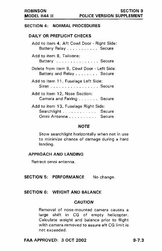
SECTION 4: NORMAL PROCEDURES
DAILY OR PREFLIGHT CHECKS
15. Inflatable FloatsFloat Pressure . . . . . . . . . . Check (See Section 2)Float Condition . . . . . . . . . Check
CAUTION
Helicopters equipped with inflated floats have an adverse roll characteristic. When sideslipping nose left or right, helicopter will tend to roll in opposite direction and could cause loss of control. To avoid adverse roll, keep helicopter trimmed with zero sideslip. Exercise extreme caution when performing simulated power failures.
CAUTION
Avoid night flight over water beyond autorotation distance to land. Height above water may be difficult to judge during a water landing.

SECTION 4: NORMAL PROCEDURES (cont'd)
OPERATION ON WATER
CAUTION
Except for actual emergencies, maximum weight for water operations is 2400 lb.
Safe operation on water has been demonstrated in waves up to 1 foot (0.3 m) (trough to crest). Maximum recommended water taxi speed is 5 knots. Some application of collective is required.
Since the helicopter sits very low on water, it is likely that water will leak into the cabin. Water landings should be limited to emergencies and training. For training, seal the removable belly panels and landing gear cross tube cover using aluminum foil tape or duct tape. Avoid salt water if possible.
There may be limited tail rotor clearance to water, particularly at aft CG. Also, even small waves may cause enough rocking to dip the tail rotor in the water. If tail rotor contact with water is suspected, have tail rotor inspected prior to further flight. (If no noticeable change in vibration occurs after suspected water contact, helicopter may be repositioned to nearest convenient inspection site.)
CAUTION
If starting or stopping rotor on water, ensure area is clear as helicopter can rotate one or more complete turns while tail rotor RPM is low.
ROBINSON MODEL R44 II
SECTION 9FIXED FLOATS SUPPLEMENT
FAA APPROVED: 17 DEC 2019 9-5.8

ROBINSON MODEL R44 II
SECTION 9FIXED FLOATS SUPPLEMENT
FAA APPROVED: 17 DEC 2019 9-5.9
SECTION 4: NORMAL PROCEDURES (cont'd)
PRACTICE AUTOROTATION – WITH GROUND CONTACT
Same as in basic manual. Autorotations should only be performed to a smooth, hard surface to avoid damage to floats.
PRACTICE AUTOROTATION TO WATER
Same as practice autorotation with ground contact in basic manual except touch down in slight nose high attitude with nose straight ahead. Maintain cyclic in touchdown position and do not lower collective full down until forward motion has stopped.
CAUTION
Lowering collective rapidly or applying excessive forward cyclic while helicopter is moving forward on water can cause floats to submerge and helicopter to nose over.
CAUTION
There may be limited tail rotor clearance to water, particularly at aft CG. Applying excessive aft cyclic may cause tail rotor to contact water.

FAA APPROVED: 3 OCT 2002 9-5.10
SECTION 5: PERFORMANCE
AIRSPEED CALIBRATION CURVE
R44 WITH FIXED FLOAT LANDING GEAR
ROBINSON MODEL R44 II
SECTION 9FIXED FLOATS SUPPLEMENT

REVISED: 17 DEC 2019 9-5.11
ROBINSON MODEL R44 II
SECTION 9FIXED FLOATS SUPPLEMENT
SECTION 6: WEIGHT AND BALANCE
CAUTION
When changing between float and non-float configurations, weight and balance must be revised and autorotation RPM readjusted per R44 Maintenance Manual.
WEIGHT AND BALANCE RECORD
Basic empty weight and CG in float and non-float configurations is included in the Weight and Balance Summary provided with the helicopter. Modifications are to be recorded in the Weight and Balance Record.
SECTION 7: SYSTEMS DESCRIPTION
The fixed-float landing gear installation includes inflated floats, additional airframe sealing and corrosion protection, additional forward position lights in the mast fairing, longer landing gear struts, and an additional stabilizer installed at the base of the lower vertical stabilizer. Standard landing gear may be installed in place of the float landing gear per maintenance manual instructions.
ROBINSON MODEL R44 II
SECTION 9FIXED FLOATS SUPPLEMENT
SECTION 8: HANDLING AND MAINTENANCE
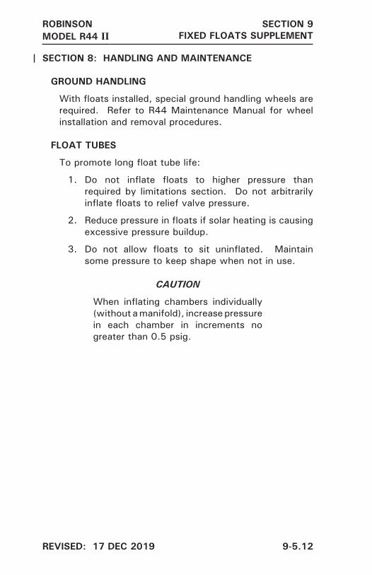
GROUND HANDLING
With floats installed, special ground handling wheels are required. Refer to R44 Maintenance Manual for wheel installation and removal procedures.
FLOAT TUBES
To promote long float tube life:
1. Do not inflate floats to higher pressure than required by limitations section. Do not arbitrarily inflate floats to relief valve pressure.
2. Reduce pressure in floats if solar heating is causing excessive pressure buildup.
3. Do not allow floats to sit uninflated. Maintain some pressure to keep shape when not in use.
CAUTION
When inflating chambers individually (without a manifold), increase pressure in each chamber in increments no greater than 0.5 psig.
REVISED: 17 DEC 2019 9-5.12


ROBINSONMODEL R44 II
SECTION 9POP-OUT FLOATS SUPPLEMENT
9-10.1
FAA APPROVEDR44 II PILOT’S OPERATING HANDBOOK
POP-OUT FLOATS SUPPLEMENT
This supplement must be included in the FAA-approved Pilot’s Operating Handbook when pop-out floats are installed.
Information contained herein supplements or supersedes the .tnemelppus siht ni detsil saera esoht ni ylno launam cisab
For limitations, procedures, and performance information not contained in this supplement, consult the basic Pilot’s Operating Handbook.
APPROVED BY:Manager, Flight Test Branch ANM-160LFederal Aviation AdministrationLos Angeles Aircraft Certification Office,Transport Airplane Directorate
DATE:
LOG OF REVISIONS
Page No. Date
9-10.89-10.9 9-10.109-10.11*9-10.12*9-10.13*9-10.14*
18 Dec 201518 Dec 201518 Dec 201518 Dec 201518 Dec 201518 Dec 201518 Dec 2015
* Manufacturer’s data, not FAA approved.
Page No. Date
9-10.19-10.2*9-10.39-10.49-10.59-10.69-10.7
18 Dec 201518 Dec 201518 Dec 201518 Dec 201518 Dec 201518 Dec 201518 Dec 2015
REVISIONSAPPROVED BY:
Manager, Flight Test Branch ANM-160LFederal Aviation AdministrationLos Angeles Aircraft Certification Office,Transport Airplane Directorate
DATE:

REVISED: 18 DEC 2015 9-10.2
SECTION 1: GENERAL
INTRODUCTION
This supplement contains the changes and additional data applicable when pop-out floats are installed.
Pop-out floats are intended for safety during over-water flights. Intentional water landings for other than training purposes are not recommended.
NOTE
The pop-out floats are not certified for ditching. Some countries may prohibit certain over-water operations.
ROBINSONMODEL R44 II
SECTION 9POP-OUT FLOATS SUPPLEMENT

FAA APPROVED: 18 DEC 2015 9-10.3
SECTION 2: LIMITATIONS
AIRSPEED LIMITS
ADDITIONAL AIRSPEED LIMITS
100 KIAS maximum at power above MCP.
With floats stowed, 100 KIAS maximum with any combination of cabin doors removed.
80 KIAS maximum for float inflation.
80 KIAS maximum with floats inflated.
115 KIAS maximum with float system armed (safety catch in READY position).
WEIGHT LIMITS
Maximum weightfor intentional water operations 2400 lb (1091 kg)
FLIGHT AND MANEUVER LIMITATIONS
Maximum altitude decrease with floats inflated is 4000 feet.
CAUTION
Altitude loss greater than 4000 feet may cause floats to lose shape and rigidity due to atmospheric pressure increase. Do not inflate floats above 4000 feet AGL.
Water landings for any reason other than an actual emergency are prohibited at weights above 2400 lb (1091 kg).
PLACARDS
Near inflation lever:
Vne WITH FLOATS INFLATED: 80 KIAS
ROBINSONMODEL R44 II
SECTION 9POP-OUT FLOATS SUPPLEMENT

FAA APPROVED: 18 DEC 2015 9-10.4
SECTION 3: EMERGENCY PROCEDURES
POWER FAILURE – GENERAL
CAUTION
Lowering collective rapidly or applying excessive forward cyclic while helicopter is moving forward on water can cause floats to submerge and helicopter to nose over.
CAUTION
Float inflation may take up to three seconds. Squeeze inflation lever early enough to allow full inflation before water contact.
POWER FAILURE ABOVE 500 FEET AGL
Autorotation to land: Same as in basic manual.
Autorotation to water:
1. Lower collective immediately to maintain rotor RPM.
2. Reduce airspeed to below 80 KIAS.
3. Adjust collective to keep RPM between 97 and 108% or apply full down collective if light weight prevents attaining above 97%.
4. If altitude permits, maneuver into wind.
5. Inflate floats.
CAUTION
Do not inflate floats above 80 KIAS. Do not exceed 80 KIAS with floats inflated.
6. At about 40 feet AGL, begin cyclic flare.
7. At about 8 feet AGL, apply forward cyclic and raise collective just before touchdown. Touch down in slight nose high attitude with nose straight ahead.
8. Maintain cyclic in touchdown position and do not lower collective full down until forward motion has stopped.
ROBINSONMODEL R44 II
SECTION 9POP-OUT FLOATS SUPPLEMENT
FAA APPROVED: 18 DEC 2015 9-10.5
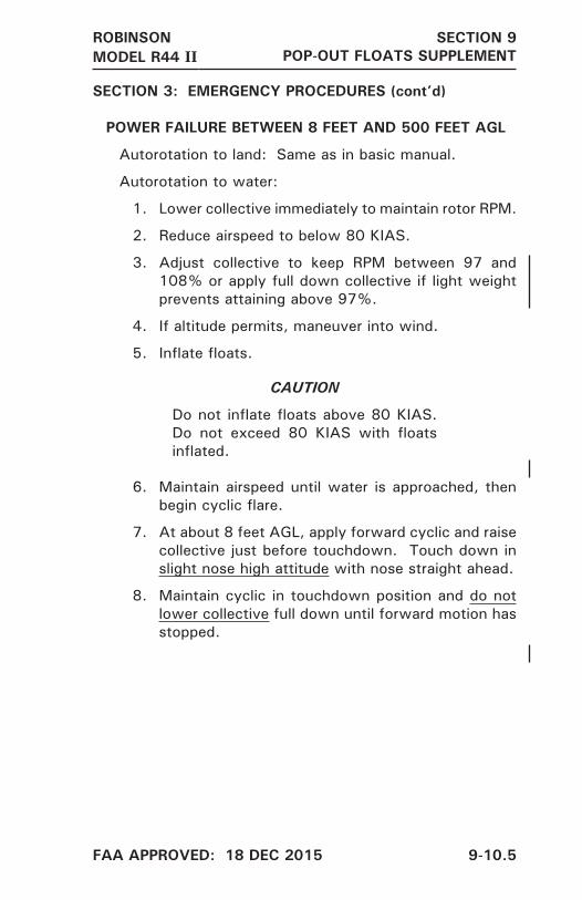
SECTION 3: EMERGENCY PROCEDURES (cont’d)
POWER FAILURE BETWEEN 8 FEET AND 500 FEET AGL
Autorotation to land: Same as in basic manual.
Autorotation to water:
1. Lower collective immediately to maintain rotor RPM.
2. Reduce airspeed to below 80 KIAS.
3. Adjust collective to keep RPM between 97 and 108% or apply full down collective if light weight prevents attaining above 97%.
4. If altitude permits, maneuver into wind.
5. Inflate floats.
CAUTION
Do not inflate floats above 80 KIAS. Do not exceed 80 KIAS with floats inflated.
6. Maintain airspeed until water is approached, then begin cyclic flare.
7. At about 8 feet AGL, apply forward cyclic and raise collective just before touchdown. Touch down in slight nose high attitude with nose straight ahead.
8. Maintain cyclic in touchdown position and do not lower collective full down until forward motion has stopped.
ROBINSONMODEL R44 II
SECTION 9POP-OUT FLOATS SUPPLEMENT

FAA APPROVED: 18 DEC 2015 9-10.6
SECTION 3: EMERGENCY PROCEDURES (cont’d)
POWER FAILURE BELOW 8 FEET AGL
Over land: Same as in basic manual.
Over water:
1. Apply right pedal as required to prevent yawing.
2. Inflate floats.
3. Allow rotorcraft to settle.
4. Raise collective just before touchdown.
MAXIMUM GLIDE DISTANCE CONFIGURATION
Same as in basic manual except airspeed 80 KIAS with floats inflated.
EMERGENCY WATER LANDING – POWER OFF
See procedures for power failures in this supplement.
EMERGENCY WATER LANDING – POWER ON
1. Reduce airspeed to below 80 KIAS.
2. Inflate floats.
CAUTION
Do not inflate floats above 80 KIAS. Do not exceed 80 KIAS with floats inflated.
3. Make normal approach and landing to water.
ROBINSONMODEL R44 II
SECTION 9POP-OUT FLOATS SUPPLEMENT

FAA APPROVED: 18 DEC 2015 9-10.7
SECTION 4: NORMAL PROCEDURES
DAILY OR PREFLIGHT CHECKS
15. Pop-Out Floats
Float and float cover condition . . . . . . . . . . . CheckHose and fitting condition . . . . . . . . . . . . . . . CheckPressure cylinder . . . . . . . . . . . . . . . Check pressureSafety pin at pressure cylinder . . . . . Verify removedInflation lever safety . . . . . . . . . “Ready” or “Locked”
as required
CAUTION
Avoid night flight over water beyond autorotation distance to land. Height above water may be difficult to judge during a water landing.
NOTE
When OAT is below -10°C, there may be insufficient charge in pressure cylinder for full inflation.
FLOAT INFLATION
The red inflation lever located under the pilot’s collective is equipped with a safety catch to prevent inadvertent float inflation. Prior to overwater flight, place the safety catch in the READY position. With the safety catch in the READY position, floats may be inflated by squeezing inflation lever.
Over land, safety catch should be reset to LOCKED position.
CAUTION
Observe 115 KIAS speed limitation when safety catch is in READY position.
ROBINSONMODEL R44 II
SECTION 9POP-OUT FLOATS SUPPLEMENT

FAA APPROVED: 18 DEC 2015 9-10.8
SECTION 4: NORMAL PROCEDURES (cont’d)
FLOAT INFLATION (cont’d)
CAUTION
The pressure cylinder also has provisions for a safety pin at the valve on the cylinder neck. This safety pin is for use during maintenance and cylinder transport only and must be removed at all other times.
NOTE
Some flapping of float covers during flight with floats inflated is normal. To minimize wear, consider removing covers if an extended flight with inflated floats is required.
ROBINSONMODEL R44 II
SECTION 9POP-OUT FLOATS SUPPLEMENT

FAA APPROVED: 18 DEC 2015 9-10.9
SECTION 4: NORMAL PROCEDURES (cont’d)
OPERATION ON WATER
Safe operation on water has been demonstrated in waves up to 1 foot (0.3 m) (trough to crest). Maximum recommended water taxi speed is 5 knots. Some application of collective is required.
Since the helicopter sits very low on water, it is likely that water will leak into the cabin. Intentional water landings should be limited to training. For training, seal the removable belly panels and landing gear cross tube cover using aluminum foil tape or duct tape. Avoid salt water if possible.
There may be limited tail rotor clearance to water, particularly at aft CG. Also, even small waves may cause enough rocking to dip the tail rotor in the water. If tail rotor contact with water is suspected, have tail rotor inspected prior to further flight. (If no noticeable change in vibration occurs after suspected water contact, helicopter may be repositioned to nearest convenient inspection site.)
CAUTION
Except for actual emergencies, maximum weight for water operation is 2400 lb (1091 kg).
CAUTION
If starting or stopping rotor on water, ensure area is clear as helicopter can rotate one or more complete turns while tail rotor RPM is low.
ROBINSONMODEL R44 II
SECTION 9POP-OUT FLOATS SUPPLEMENT
FAA APPROVED: 18 DEC 2015 9-10.10
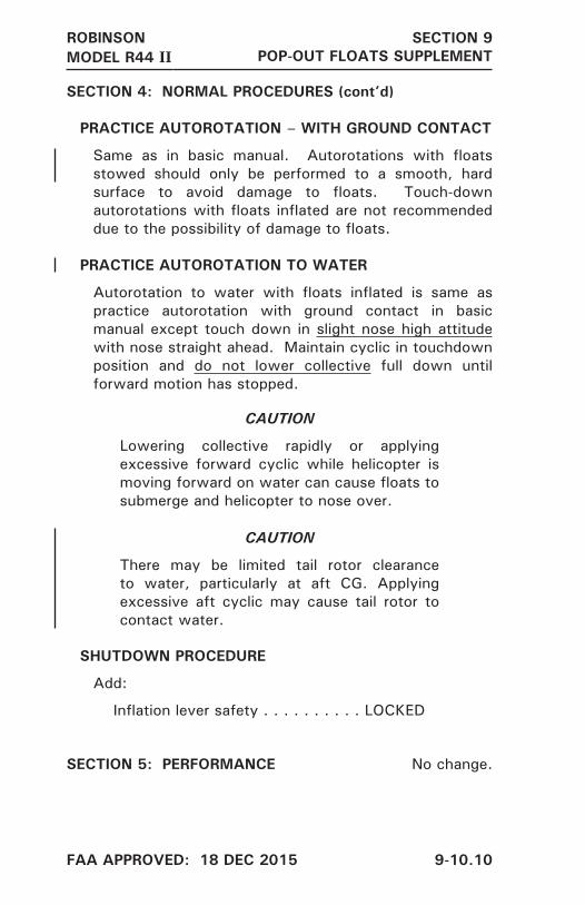
SECTION 4: NORMAL PROCEDURES (cont’d)
PRACTICE AUTOROTATION – WITH GROUND CONTACT
Same as in basic manual. Autorotations with floats stowed should only be performed to a smooth, hard surface to avoid damage to floats. Touch-down autorotations with floats inflated are not recommended due to the possibility of damage to floats.
PRACTICE AUTOROTATION TO WATER
Autorotation to water with floats inflated is same as practice autorotation with ground contact in basic manual except touch down in slight nose high attitude with nose straight ahead. Maintain cyclic in touchdown position and do not lower collective full down until forward motion has stopped.
CAUTION
Lowering collective rapidly or applying excessive forward cyclic while helicopter is moving forward on water can cause floats to submerge and helicopter to nose over.
CAUTION
There may be limited tail rotor clearance to water, particularly at aft CG. Applying excessive aft cyclic may cause tail rotor to contact water.
SHUTDOWN PROCEDURE
Add:
Inflation lever safety . . . . . . . . . . LOCKED
SECTION 5: PERFORMANCE No change.
ROBINSONMODEL R44 II
SECTION 9POP-OUT FLOATS SUPPLEMENT

ISSUED: 18 DEC 2015 9-10.11
SECTION 6: WEIGHT AND BALANCE
WEIGHT AND BALANCE RECORD
Basic empty weight and CG with pop-out float landing gear and pressure cylinder installed are included in the Weight and Balance Summary provided with the helicopter. If pressure cylinder is removed, update Weight and Balance Record. A charged pressure cylinder weighs 11.4 lb. The longitudinal arm of the cylinder is 41.2 inches from datum and the lateral arm is -8.5 inches from datum.
SECTION 7: SYSTEMS DESCRIPTION
The pop-out float system consists of inflatable floats stowed in protective covers along the skid tubes, a pressure cylinder located in the compartment under the left front seat, flexible hoses from the cylinder to the floats, an inflation lever located on the pilot’s collective, and an additional stabilizer installed at the base of the lower vertical stabilizer.
The pressure cylinder is of aluminum construction reinforced with carbon filament windings and is charged with helium. Proper pressure is indicated on a placard on the cylinder, and pressure can be checked using the gage on the cylinder valve.
A safety catch on the inflation lever can be set to prevent inadvertent actuation. With the safety catch in the READY position, floats are inflated by squeezing firmly on the inflation lever. (Approximately 20 lb force is required.) Float inflation time is approximately 2-3 seconds. With the safety catch in the LOCKED position, the inflation lever is locked out.
To operate the safety catch, push spring-loaded knob with thumb while rotating U-shaped pin with forefinger as shown in figure.
ROBINSONMODEL R44 II
SECTION 9POP-OUT FLOATS SUPPLEMENT

ISSUED: 18 DEC 2015 9-10.12
ROBINSONMODEL R44 II
SECTION 9POP-OUT FLOATS SUPPLEMENT

ISSUED: 18 DEC 2015 9-10.13
SECTION 7: SYSTEMS DESCRIPTION (cont’d)
The pop-out floats are approved for amphibious operation but are not certified for ditching. They are intended for enhanced safety during over-water flights. Intentional water landings for other than training purposes are not recommended.
NOTE
Floats maintain full pressure for at least 1 hour after inflation and typically maintain shape for several hours. Monitor float inflation state if helicopter is parked on water for an extended period.
SECTION 8: HANDLING AND MAINTENANCE
GROUND HANDLING
With floats installed, special ground handling wheels (Robinson part number MT980-1 and MT980-2) are required.
A safety pin is provided for installation at the pressure cylinder valve. This pin should be installed during maintenance and cylinder transport to prevent inadvertent pressure release.
CAUTION
With the safety pin installed, it is not possible to inflate the floats using the cockpit inflation lever. The safety pin is for use during maintenance and cylinder transport only and must be removed at all other times.
FLOAT TUBES AND COVERS
Immediately replace any damaged float tube cover to minimize chance of float damage. Inspect float tube condition after each inflation. Refer to R44 Maintenance Manual for periodic inspection, float repacking, and cylinder recharge instructions.
ROBINSONMODEL R44 II
SECTION 9POP-OUT FLOATS SUPPLEMENT

INTENTIONALLY BLANK
ISSUED: 18 DEC 2015 9-10.14


ROBINSONR44, R44 II, R44 CADET
SECTION 9ADS-B EQUIP. SUPPLEMENT
9-12.1
FAA APPROVEDR44, R44 II, R44 CADET
PILOT’S OPERATING HANDBOOK
ADS-B EQUIPMENT SUPPLEMENT
This supplement must be included in the FAA-approved Pilot’s Operating Handbook when ADS-B equipment is installed.
The information contained herein supplements or supersedes .tnemelppus siht ni detsil saera esoht ni ylno launam cisab eht
For limitations, procedures, and performance information not contained in this supplement, consult the basic Pilot’s Operating Handbook.
APPROVED BY:Manager, Flight Test Branch, ANM-160LFederal Aviation Administration, LAACOTransport Airplane Directorate
DATE:
LOG OF PAGES
PageNo. Date
9-12.19-12.2*9-12.3*
27 JUN 1627 JUN 1627 JUN 16
PageNo. Date
9-12.49-12.59-12.6*
27 JUN 1627 JUN 1627 JUN 16
*Manufacturer’s data, not FAA approved.

ISSUED: 27 JUN 2016 9-12.2
SECTION 1: GENERAL
INTRODUCTION
This supplement contains the changes and additional data applicable when Automatic Dependent Surveillance-Broadcast (ADS-B) equipment is installed.
ADS-B is divided into two categories – ADS-B “Out” and ADS-B “In”.
ADS-B Out equipment transmits information to air traffic control to supplement radar/transponder information. The supplemental information allows optimization of flight plan routes and aircraft spacing.
ADS-B Out equipment may be required for operation in certain airspace. The R44 ADS-B Out installation has been shown to meet the requirements of 14 CFR § 91.227.
NOTE
The R44 ADS-B Out system operates on frequency 1090 MHz. This frequency is also accepted for ADS-B Out equipment in most countries outside the United States.
The ADS-B Out equipment consists of either a GPS receiver connected to the transponder or a transponder with built-in GPS. The transponder has ADS-B broadcast capability and broadcasts GPS position as well as additional preprogrammed information such as aircraft identification and type to air traffic control.
ADS-B In equipment receives traffic information from other ADS-B equipped aircraft. ADS-B In equipment may also receive additional traffic information and weather information from ground stations. The additional traffic and weather information from ground stations is only available in the United States
ROBINSONR44, R44 II, R44 CADET
SECTION 9ADS-B EQUIP. SUPPLEMENT

ISSUED: 27 JUN 2016 9-12.3
SECTION 1: GENERAL (cont’d)
INTRODUCTION (cont’d)
The ADS-B In equipment consists of a receiver (either installed under the left, front seat or built in to the transponder) and a suitable display. Refer to receiver and display manufactures’ documentation for operation of ADS-B In equipment.
The R44 may be equipped with only ADS-B Out or with both ADS-B Out and ADS-B In.
ROBINSONR44, R44 II, R44 CADET
SECTION 9ADS-B EQUIP. SUPPLEMENT

FAA APPROVED: 27 JUN 2016 9-12.4
SECTION 2: LIMITATIONS
PLACARDS
On transponder when ADS-B Out equipment is installed:
ADS-B OUT INSTALLED
SECTION 3: EMERGENCY PROCEDURES No change.
SECTION 4: NORMAL PROCEDURES
ADS-B SYSTEM OPERATION
ADS-B system operation is mostly automatic and requires little pilot action. The GPS (if separate from the transponder), transponder, and ADS-B receiver (if installed) must all be powered and in normal operating modes for proper system function.
ADS-B OUT
The R44 ADS-B Out system is a single point of entry system. Mode 3/A codes, IDENT commands, and emergency codes are set on the transponder and are automatically incorporated in ADS-B Out broadcasts. The transponder should transition to ALT mode after takeoff for proper ADS-B Out broadcasts.
ADS-B Out broadcasts may be selected off by using menus associated with the transponder FUNC key.
NOTE
ADS-B Out may be required in certain airspace. Do not turn off ADS-B Out unless directed by air traffic control.
Malfunctions in the ADS-B Out system are annunciated by various messages on the transponder and/or GPS screen (refer to manufacturers’ documentation).
ROBINSONR44, R44 II, R44 CADET
SECTION 9ADS-B EQUIP. SUPPLEMENT

FAA APPROVED: 27 JUN 2016 9-12.5
SECTION 4: NORMAL PROCEDURES (cont’d)
ADS-B SYSTEM OPERATION (cont’d)
ADS-B IN
The ADS-B In receiver is either mounted underneath the left, front seat or is built in to the transponder. The receiver is powered by the Transponder/ADS-B circuit breaker.
ADS-B In data is sent from the receiver to a suitable display, often the primary GPS screen. The display may have dedicated traffic and weather views or may allow traffic and weather information to be overlaid on other data such as moving maps. Warnings such as traffic conflicts may also appear on the display. Refer to receiver and display manufacturers’ documentation.
SECTION 5: PERFORMANCE No change.
ROBINSONR44, R44 II, R44 CADET
SECTION 9ADS-B EQUIP. SUPPLEMENT

ISSUED: 27 JUN 2016 9-12.6
SECTION 6: WEIGHT AND BALANCE No change.
SECTION 7: SYSTEM DESCRIPTION
ADS-B SYSTEM
The ADS-B Out system consists of either a GPS receiver connected to the transponder or a transponder with built-in GPS. The transponder broadcasts the aircraft’s position, identification, and certain other parameters to air traffic control. ADS-B data is broadcast via the Extended Squitter (ES) feature of the transponder on a frequency of 1090 MHz. Note that change of aircraft registration may require update of pre-programmed parameters by qualified maintenance personnel.
Most of the data required for ADS-B broadcast such as aircraft type, ICAO address, and call sign are pre-programmed at installation. Flight-specific data such as Mode 3/A code and IDENT are entered using the transponder controls. The transponder uses these codes simultaneously for standard transponder as well as ADS-B broadcasts. There is no need to make a second code entry or to enter a code more than once. This is known as a “single point of entry” ADS-B system.
The ADS-B In system consists of a receiver (either mounted under the left, front seat or built in to the transponder) and a suitable display. The receiver receives both approved US ADS-B frequencies (978 MHz and 1090 MHz).
SECTION 8: HANDLING, SERVICING AND MAINTENANCE
No change.
ROBINSONR44, R44 II, R44 CADET
SECTION 9ADS-B EQUIP. SUPPLEMENT

9-13.1
FAA APPROVEDR44, R44 II, R44 CADET
PILOT’S OPERATING HANDBOOK
HELISAS AUTOPILOT SUPPLEMENT
This supplement must be included in the FAA-approved Pilot’s Operating Handbook when the HeliSAS autopilot is installed.
The information contained herein supplements or supersedes .tnemelppus siht ni detsil saera esoht ni ylno launam cisab eht
For limitations, procedures, and performance information not contained in this supplement, consult the basic Pilot’s Operating Handbook.
APPROVED BY:Manager, Flight Test Branch, ANM-160LFederal Aviation Administration, LAACOTransport Airplane Directorate
DATE:
LOG OF REVISIONS
PageNo. Date
9-13.19-13.29-13.39-13.49-13.59-13.6*
17 Dec 1917 Dec 1917 Dec 1917 Dec 1917 Dec 1917 Dec 19
* Manufacturer’s data, not FAA approved.
PageNo. Date
9-13.7*9-13.8*9-13.9*9-13.10*9-13.11*9-13.12*
17 Dec 1917 Dec 1917 Dec 1917 Dec 1917 Dec 1917 Dec 19
REVISIONSAPPROVED BY:
Manager, West Flight Test Section, AIR-716Federal Aviation AdministrationLos Angeles
DATE: 17 DEC 2019
ROBINSONR44, R44 II, R44 CADET
SECTION 9HELISAS AUTOPILOT

FAA APPROVED: 17 DEC 2019 9-13.2
ROBINSONR44, R44 II, R44 CADET
SECTION 9HELISAS AUTOPILOT
SECTION 1: GENERAL
INTRODUCTION
This supplement contains the changes and additional data applicable when the HeliSAS autopilot is installed.
CAUTION
The autopilot is intended to enhance safety by reducing pilot workload. It is not a substitute for adequate pilot skill nor does it relieve the pilot of the responsibility to monitor the flight controls and maintain adequate outside visual reference.
The primary autopilot mode is Stability Augmentation System (SAS) mode which maintains a steady helicopter attitude by applying corrective inputs to the cyclic. The autopilot does not provide any collective or pedal inputs. Additional modes providing heading hold, altitude hold, and navigation functionality are also selectable.
SECTION 2: LIMITATIONS
FLIGHT AND MANEUVER LIMITATIONS
Minimum altitude for use of autopilot ALT mode is 200 feet AGL.
For practice instrument approaches, minimum altitude for use of autopilot VRT mode is 50 feet AGL.
Pilot’s hand must be on cyclic grip under the following conditions:
During autopilot engagement or intentional disengage-ment
At airspeeds less than 50 KIAS when less than 500 feet AGL

FAA APPROVED: 17 DEC 2019 9-13.3
ROBINSONR44, R44 II, R44 CADET
SECTION 9HELISAS AUTOPILOT
SECTION 3: EMERGENCY PROCEDURES
AUTOPILOT DISENGAGEMENT OR FAILURE
The autopilot is designed to automatically disengage if the system detects a fault. Disengagement is normally indicated by four beeps in the headset. If the autopilot does not automatically disengage, failure may be recognized by erratic cyclic control motion, abnormal cyclic stick forces, or deviations in pitch or roll.
1. Continue flight using manual control. If autopilot has not disengaged, manually disengage using cyclic AP OFF button or control panel SAS button.
2. If SAS annunciator on control panel is steady white, re-engagement may be attempted at pilot’s discretion.
CAUTION
Due to the unstable nature of helicopters, autopilot disengagement requires immediate pilot attention. Always monitor helicopter attitude and flight controls, and be prepared to take manual control.
NOTE
The system automatically switches off all modes except SAS mode at airspeeds below 44 KIAS or above 130 KIAS, accompanied by a single beep. This is by design and not a system failure. The high speed limit is not intended to provide Vne protection. It is the pilot’s responsibility to observe Vne limits.
NOTE
Although unlikely, it is possible for certain faults to cause disengagement without the four-beep aural warning.

FAA APPROVED: 17 DEC 2019 9-13.4
ROBINSONR44, R44 II, R44 CADET
SECTION 9HELISAS AUTOPILOT
SECTION 4: NORMAL PROCEDURES
GENERAL
Autopilot controls and operating modes are described in Section 7, Systems Description.
NOTE
Cyclic friction must be fully off for autopilot to work properly. Cyclic friction will degrade autopilot performance.
STARTING ENGINE AND RUN-UP
After “Hydraulic system”, add:
Autopilot . . . . . . . . . . . . . . . . . . . . . . . . . . Check
NOTE
For autopilot check, wear headset and ensure cyclic friction is off. Engage SAS mode. Verify cyclic exhibits centering tendency and SAS annunciator on control panel turns green. Disengage. Verify 4 beeps in headset, cyclic reverts to normal hydraulic system feel, and SAS annunciator turns white.
TAKEOFF PROCEDURE
Autopilot SAS mode may be engaged as desired on the ground or at any time during the takeoff procedure. Re-trim as necessary to eliminate undesirable cyclic forces.

FAA APPROVED: 17 DEC 2019 9-13.5
ROBINSONR44, R44 II, R44 CADET
SECTION 9HELISAS AUTOPILOT
SECTION 4: NORMAL PROCEDURES (cont’d)
CRUISE
Add:
Engage autopilot modes as desired. In SAS mode, re-trim as necessary to eliminate undesirable cyclic forces.
CAUTION
It is the pilot’s responsibility to monitor flight controls, aircraft flightpath, traffic, and terrain even while the autopilot is engaged. The autopilot is designed to disengage in the event of a fault. Be prepared to take control if required.
SECTION 5: PERFORMANCE No change.

REVISED: 17 DEC 2019 9-13.6
ROBINSONR44, R44 II, R44 CADET
SECTION 9HELISAS AUTOPILOT
SECTION 6: WEIGHT AND BALANCE No change.
SECTION 7: SYSTEMS DESCRIPTION
AUTOPILOT
The HeliSAS autopilot system consists of two electric servomotors, a flight control computer, an autopilot control panel, and control buttons on the cyclic grip. One servomotor controls pitch and is installed in the control tunnel forward of the cyclic stick. The other servomotor controls roll and is installed under the pilot’s seat. The servomotors are connected to the cyclic through electromagnetic clutches.
The flight control computer is installed on the forward panel under the pilot’s seat, and the autopilot control panel is installed in the avionics stack.
In addition to the autopilot system components, an onboard attitude source such as an Attitude Heading Reference System (AHRS) is required.
The primary autopilot mode is Stability Augmentation System (SAS) mode which maintains a steady helicopter attitude by applying corrective inputs to the cyclic. This is felt as a light cyclic centering force. The autopilot senses aircraft attitude using a combination of sensors in the flight control computer and the onboard attitude source. The computer then sends signals to the servomotors which are connected to the bottom of the cyclic in the control tunnel. Additional modes may be layered on top of SAS mode and are described below.

REVISED: 17 DEC 2019 9-13.7
ROBINSONR44, R44 II, R44 CADET
SECTION 9HELISAS AUTOPILOT
SECTION 7: SYSTEMS DESCRIPTION (cont’d)
AUTOPILOT (cont’d)
Heading Mode (HDG) – maintains the heading selected by the heading bug on the directional gyro or Horizontal Situation Indicator (HSI) display. Aircraft can be steered using the heading bug.
NOTE
For large heading or course changes, the autopilot will use a maximum of 20° bank.
Altitude Mode (ALT) – maintains altitude at the time of engagement or of last TRIM button release. The target altitude is reset each time the TRIM button is pressed and released.
NOTE
The autopilot uses pitch attitude to maintain altitude or follow an approach glidepath. It does not have any control of power setting. The pilot must manage power with the collective to control speed and rate of climb or descent. Make small, smooth power changes to allow the system to adjust to new power settings.
Navigation Mode (NAV) – tracks the active GPS or VLOC course displayed on the Course Deviation Indicator (CDI). If no CDI is installed, NAV will only track the active GPS course displayed on the GPS.
NAV may be armed prior to intercepting the active course. NAV annunciator is white when NAV is armed and turns green at course intercept. If HDG is active when NAV is armed, the autopilot will fly the selected heading until course intercept. If HDG is not active, the autopilot will select a 45° intercept angle.

REVISED: 17 DEC 2019 9-13.8
ROBINSONR44, R44 II, R44 CADET
SECTION 9HELISAS AUTOPILOT
SECTION 7: SYSTEMS DESCRIPTION (cont’d)
AUTOPILOT (cont’d)
Vertical Navigation Mode (VRT) – tracks an ILS glideslope or GPS approach vertical guidance. Arm VRT (annunciator turns white when armed) prior to intercepting the glidepath. VRT annunciator will turn green at glidepath intercept.
NOTE
Pushing the ALT button while VRT is armed or active will turn off VRT. VRT must be re-armed or re-engaged as desired.
NOTE
Reducing power to approach setting just prior to glidepath intercept is recommended.

REVISED: 17 DEC 2019 9-13.9
ROBINSONR44, R44 II, R44 CADET
SECTION 9HELISAS AUTOPILOT
SECTION 7: SYSTEMS DESCRIPTION (cont’d)
AUTOPILOT (cont’d)
Backcourse Mode (BC) – reverse CDI sensing for backcourse approaches. Course on HSI should be set so that tail of course pointer points toward runway (set to inbound front course).
The control panel has a row of buttons to control autopilot modes and annunciators to indicate mode status. A dark annunciator indicates that a mode is off, a white annunciator indicates that a mode is armed or on standby, and a green annunciator indicates that a mode is active.
When the avionics master is switched on, the autopilot performs a self-test and then enters SAS standby mode. All of the control panel indicators flash alternating white and green during the self-test. Four headset beeps occur at the beginning of the self-test as a check of the aural warning function. The SAS annunciator on the control panel turns steady white when the self-test is complete.
NOTE
Autopilot will not enter standby mode if attitude indicator is not functioning or indicated bank angle is greater than 6 degrees.

REVISED: 17 DEC 2019 9-13.10
ROBINSONR44, R44 II, R44 CADET
SECTION 9HELISAS AUTOPILOT
SECTION 7: SYSTEMS DESCRIPTION (cont’d)
AUTOPILOT (cont’d)
The autopilot SAS mode is engaged either by pressing the SAS button on the control panel or by pressing the TRIM button on the cyclic for more than 1.25 seconds. Additional modes are engaged by pressing the appropriate button on the control panel. The additional modes are disabled and will not engage at airspeeds below 44 KIAS or above 130 KIAS.
To disengage any mode, push the appropriate button on the control panel.
NOTE
Disengaging SAS mode will also disengage all other modes.
Modes may also be disengaged using the AP OFF button on the cyclic. If only SAS mode is engaged, push the AP OFF button once to disengage. If additional modes are engaged, push the AP OFF button once to disengage all modes except SAS and a second time to disengage SAS mode, or push and hold the AP OFF button to disengage all modes including SAS.
NOTE
SAS disengagement should always be accompanied by four beeps in the headset. If beeps do not occur, maintenance is required.
Safety monitors automatically disengage individual modes or the entire system if a fault is detected. Automatic disengagement of SAS mode (or the entire system) is indicated by four beeps in the headset. Automatic disengagement of any mode other than SAS is indicated by a single beep in the headset. There is no audio indication for intentional disengagement of modes other than SAS.

ROBINSONR44, R44 II, R44 CADET
SECTION 9HELISAS AUTOPILOT
ISSUED: 17 DEC 2019 9-13.11
SECTION 7: SYSTEMS DESCRIPTION (cont’d)
AUTOPILOT (cont’d)
NOTE
The system also automatically reverts to SAS mode at airspeeds below 44 KIAS or above 130 KIAS, accompanied by a single beep. The high speed limit is not intended to provide Vne protection. It is the pilot’s responsibility to observe Vne limits.
The TRIM button is used to re-set the target attitude (to re-trim) while in SAS mode. Use a small amount of force to override the autopilot and then push and release the TRIM button at the new desired condition. If the force to override is objectionable, the TRIM button may be held down during maneuvers. The system will re-trim to the attitude at which the TRIM button is released.
NOTE
The system will not re-trim to more than 6° nose down, 11° nose up, or 10° of bank. If a re-trim is attempted outside these limits, the system will trim to the limiting value.
NOTE
When engaging SAS mode from standby, the autopilot uses the helicopter attitude at the time SAS mode is engaged as the target (trim) attitude. For large pitch and roll angles at the time of engagement, a target of 2° nose up pitch and 0° (level) roll is used.
The autopilot is protected by a dedicated circuit breaker on the avionics bus (autopilot is not powered with the avionics master switch off).

ROBINSONR44, R44 II, R44 CADET
SECTION 9HELISAS AUTOPILOT
ISSUED: 17 DEC 2019 9-13.12
SECTION 7: SYSTEMS DESCRIPTION (cont’d)
REMOVABLE FLIGHT CONTROLS
On later aircraft, disconnect the electrical connector for the left-hand trim button located near the quick release pin before removing the left cyclic grip. Reconnect the connector when installing the left cyclic grip.
SECTION 8: HANDLING AND MAINTENANCE
No change.
SECTION 10: SAFETY TIPS
The autopilot is intended to reduce pilot workload and enhance safety. It is important that pilots do not misuse this capability and allow their attention to be diverted. Pilots should continue monitoring the flight controls and helicopter attitude as well as looking for traffic and other obstacles. Autopilot disengagement requires immediate pilot attention. Pilots must always be prepared to take manual control.
The autopilot is not certified for flight in Instrument Meteorological Conditions (IMC). Adhering to appropriate VFR weather minimums is essential for safety.
If an inadvertent loss of outside visual reference occurs, the pilot must regain visual conditions as quickly as possible while avoiding abrupt, disorienting maneuvers. The following procedure is recommended:
1. If not already engaged, immediately engage autopilot SAS mode and allow autopilot to recover from unusual attitude if one has occurred.
2. Select a heading and altitude to ensure terrain and obstacle clearance. Turns and/or climbs may be required. Engage additional autopilot modes as desired for workload reduction.
3. While maintaining terrain and obstacle clearance, maneuver toward conditions of improved visibility.

FAA APPROVEDR44 II PILOT’S OPERATING HANDBOOK
OPTIONAL AVIONICS SUPPLEMENT
devorppa-AAF eht ni dedulcni eb tsum tnemelppus sihTPilot’s Operating Handbook when certain factory-supplied optional avionics are installed.
Information contained herein supplements or supersedes the basic manual only in those areas listed in this supplement. For limitations, procedures, and performance information not contained in this supplement, consult the basic Pilot’s Operating Handbook.
APPROVED BY:Manager, West Flight Test Section, AIR-716Federal Aviation AdministrationLos Angeles, CA
DATE:
Page 9-14.1
PageNo. Date
9-14.19-14.2*9-14.39-14.4*9-14.5*
7 May 187 May 187 May 187 May 187 May 18
PageNo. Date
9-14.6*9-14.7*9-14.8*9-14.9*9-14.10*
7 May 187 May 187 May 187 May 187 May 18
LOG OF PAGES
* Manufacturer’s data, not FAA approved.
ROBINSON MODEL R44 II
SECTION 9OPTIONAL AVIONICS SUPPLEMENT

ISSUED: 7 MAY 2018 Page 9-14.2
SECTION 1: GENERAL
INTRODUCTION
This supplement provides additional information for certain avionics options. A set of manufacturers’ instructions for all installed avionics is provided with each new helicopter.
The following equipment is addressed in this supplement:
• Aspen Avionics EFD 1000H PFD and EFD 500H MFD
• Garmin G500H avionics system with non-touch screen display (GDU 620)
• Garmin G500H avionics system with touch screen display (GDU 1060 TXi or GDU 700L TXi)
NOTE
For all Robinson Primary Flight Display (PFD)/ Multi Function Display (MFD) installations, the airspeed indicator, altimeter, compass, tachometer, and engine instruments are retained. Pilots should use the traditional instruments as primary unless fully familiar with the installed avionics.
ROBINSON MODEL R44 II
SECTION 9OPTIONAL AVIONICS SUPPLEMENT

FAA APPROVED: 7 MAY 2018 Page 9-14.3
SECTION 2: LIMITATIONS No change.
SECTION 3: EMERGENCY PROCEDURES No change.
SECTION 4: NORMAL PROCEDURES No change.
SECTION 5: PERFORMANCE No change.
SECTION 6: WEIGHT AND BALANCE No change.
SECTION 7: SYSTEMS DESCRIPTION See below.
SECTION 8: HANDLING AND MAINTENANCE
No change.
ROBINSON MODEL R44 II
SECTION 9OPTIONAL AVIONICS SUPPLEMENT

ISSUED: 7 MAY 2018 Page 9-14.4
SECTION 7: SYSTEMS DESCRIPTION
ASPEN EFD 1000H PFD AND EFD 500H MFD
The Aspen Electronic Flight Display (EFD) 1000H is a Primary Flight Display (PFD) optimized for helicopter use. It is available in a “Pilot” (basic) version or “Pro” (with more advanced navigation features) version.
The Aspen EFD 500H is a Multifunction Display (MFD) optimized for helicopter use.
Robinson configurations are either a single EFD 1000H PFD or a dual installation with one EFD 1000H PFD and one EFD 500H MFD. A typical dual-installation instrument panel is illustrated on the following page.
The manufacturer’s documents for the EFD 1000H and EFD 500H are:
Title Document No.Aspen Avionics Evolution Flight Display EFD 1000H PFD Pilot’s Guide 091-00012-001
Aspen Avionics Evolution Flight Display EFD 1000H/500H MFD Pilot’s Guide 091-00013-001
NOTE
A Robinson part no. D327-4 light filter may be used to reduce reflections in the windshield at night. The light filter is installed by clipping it to the front of the display. Filter use is at pilot discretion.
ROBINSON MODEL R44 II
SECTION 9OPTIONAL AVIONICS SUPPLEMENT

ISSUED: 7 MAY 2018 Page 9-14.5
OPTIONAL INSTRUMENT PANEL WITH ASPEN EFD 1000H PFD and EFD 500H MFD(Exact panel configuration may vary with optional equipment and date of helicopter manufacture.)
1. AIRSPEED INDICATOR 21. GOVERNOR-OFF LIGHT2. ENGINE AND ROTOR TACHS 22. FULL THROTTLE LIGHT3. ALTIMETER 23. ROTOR BRAKE LIGHT4. MANIFOLD PRESSURE GAGE 24. IGNITION SWITCH5. CLOCK 25. CLUTCH ACTUATOR SWITCH6. MULTI-FUNCTION DISPLAY 26. OUTSIDE AIR TEMP/VOLTMETER7. PRIMARY FLIGHT DISPLAY 27. PANEL LIGHTS DIMMER8. CLUTCH ACTUATOR LIGHT 28. ENGINE INSTRUMENTS9. M.R. GEARBOX TEMP LIGHT 29. CABIN AIR
10. M.R. GEARBOX CHIP LIGHT 30. NAVIGATION LIGHTS SWITCH11. CARBON MONOXIDE LIGHT 31. ANTI-COLLISION LIGHT SWITCH12. STARTER-ON LIGHT 32. AVIONICS MASTER SWITCH13. T.R. GEARBOX CHIP LIGHT 33. ALTERNATOR SWITCH14. LOW FUEL LIGHT 34. BATTERY SWITCH15. LOW RPM LIGHT 35. MIXTURE CONTROL16. FUEL FILTER LIGHT 36. AVIONICS STACK17. AUX FUEL PUMP LIGHT 37. CYCLIC FRICTION18. ALT LOW VOLTAGE LIGHT 38. CABIN HEAT19. ENGINE FIRE LIGHT 39. ELT SWITCH (OPT’L)20. OIL PRESSURE LIGHT 40. PITOT HEAT SWITCH (OPT’L)
SECTION 7: SYSTEMS DESCRIPTION (cont’d)
ROBINSON MODEL R44 II
SECTION 9OPTIONAL AVIONICS SUPPLEMENT

SECTION 7: SYSTEMS DESCRIPTION (cont’d)
GARMIN G500H SYSTEM WITH GDU 620 (NON-TOUCH SCREEN) DISPLAY
The Garmin GDU 620 display is a split screen PFD/MFD designed for use with Garmin’s G500H helicopter avionics system.
A typical Robinson Installation is illustrated on the following page.
The manufacturer’s document for the G500H system with GDU 620 display is:
Title Document No.Garmin G500H Pilot’s Guide 190-01150-02
NOTE
A Robinson part no. D327-1 light filter may be used to reduce reflections in the windshield at night. The light filter is installed by clipping it to the front of the display. Filter use is at pilot discretion.
ISSUED: 7 MAY 2018 Page 9-14.6
ROBINSON MODEL R44 II
SECTION 9OPTIONAL AVIONICS SUPPLEMENT

ISSUED: 7 MAY 2018 Page 9-14.7
OPTIONAL INSTRUMENT PANEL WITH GARMIN G500H SYSTEM WITH GDU 620 DISPLAY
(Exact panel configuration may vary with optional equipment and date of helicopter manufacture.)
1. AIRSPEED INDICATOR 23. CLOCK2. ENGINE AND ROTOR TACHS 24. OUTSIDE AIR TEMP/VOLTMETER3. ALTIMETER 25. PANEL LIGHTS DIMMER4. MANIFOLD PRESSURE GAGE 26. ENGINE INSTRUMENTS5. FULL THROTTLE LIGHT 27. GPS NAVIGATOR6. MULTI-FUNCTION DISPLAY 28. CLUTCH ACTUATOR SWITCH7. PRIMARY FLIGHT DISPLAY 29. IGNITION SWITCH8. CLUTCH ACTUATOR LIGHT 30. ROTOR BRAKE LIGHT9. M.R. GEARBOX TEMP LIGHT 31. CABIN AIR
10. M.R. GEARBOX CHIP LIGHT 32. NAVIGATION LIGHTS SWITCH11. CARBON MONOXIDE LIGHT 33. ANTI-COLLISION LIGHT SWITCH12. STARTER-ON LIGHT 34. AVIONICS MASTER SWITCH13. T.R. GEARBOX CHIP LIGHT 35. ALTERNATOR SWITCH14. LOW FUEL LIGHT 36. BATTERY SWITCH15. LOW RPM LIGHT 37. MIXTURE CONTROL16. FUEL FILTER LIGHT 38. AUDIO CONTROL17. AUX FUEL PUMP LIGHT 39. AVIONICS STACK18. ALT LOW VOLTAGE LIGHT 40. ELT SWITCH (OPT’L)19. ENGINE FIRE LIGHT 41. CABIN HEAT20. OIL PRESSURE LIGHT 42. CYCLIC FRICTION21. GOVERNOR-OFF LIGHT 43. PITOT HEAT SWITCH (OPT’L)22. OPTIONAL INSTRUMENT
SECTION 7: SYSTEMS DESCRIPTION (cont’d)
ROBINSON MODEL R44 II
SECTION 9OPTIONAL AVIONICS SUPPLEMENT

ISSUED: 7 MAY 2018 Page 9-14.8
SECTION 7: SYSTEMS DESCRIPTION (cont’d)
GARMIN G500H SYSTEM WITH GDU 1060 TXi OR GDU 700L TXi TOUCH SCREEN DISPLAY
The Garmin GDU 1060 TXi is a 10.6 inch diagonal split screen PFD/MFD designed for use with Garmin’s G500H Helicopter Avionics System.
The Garmin GDU 700L TXi is a 7 inch diagonal PFD/MFD designed for use with Garmin’s G500H helicopter avionics system.
Both displays use a touch screen for pilot interface, with primary functions duplicated via knobs and buttons.
Robinson installations for each of the displays are illustrated on the following pages.
The manufacturer’s document for the G500H system with GDU 1060 TXi or GDU 700L TXi display is:
Title Document No.Garmin G500(H)/G600/G700 TXi Pilot’s Guide 190-01717-11
ROBINSON MODEL R44 II
SECTION 9OPTIONAL AVIONICS SUPPLEMENT

ISSUED: 7 MAY 2018 Page 9-14.9
OPTIONAL INSTRUMENT PANEL WITH GARMIN G500H SYSTEM WITH GDU 1060 TXi DISPLAY
(Exact panel configuration may vary with optional equipment and date of helicopter manufacture.)
SECTION 7: SYSTEMS DESCRIPTION (cont’d)
1. AIRSPEED INDICATOR 22. CLOCK2. ENGINE AND ROTOR TACHS 23. OUTSIDE AIR TEMP/VOLTMETER3. ALTIMETER 24. PANEL LIGHTS DIMMER4. MANIFOLD PRESSURE GAGE 25. ENGINE INSTRUMENTS5. FULL THROTTLE LIGHT 26. GPS NAVIGATOR6. PRIMARY/MULTI FXN DISPLAY 27. CLUTCH ACTUATOR SWITCH7. CLUTCH ACTUATOR LIGHT 28. IGNITION SWITCH8. M.R. GEARBOX TEMP LIGHT 29. ROTOR BRAKE LIGHT9. M.R. GEARBOX CHIP LIGHT 30. CABIN AIR
10. CARBON MONOXIDE LIGHT 31. NAVIGATION LIGHTS SWITCH11. STARTER-ON LIGHT 32. ANTI-COLLISION LIGHT SWITCH12. T.R. GEARBOX CHIP LIGHT 33. AVIONICS MASTER SWITCH13. LOW FUEL LIGHT 34. ALTERNATOR SWITCH14. LOW RPM LIGHT 35. BATTERY SWITCH15. FUEL FILTER LIGHT 36. MIXTURE CONTROL16. AUX FUEL PUMP LIGHT 37. AUDIO CONTROL17. ALT LOW VOLTAGE LIGHT 38. AVIONICS STACK18. ENGINE FIRE LIGHT 39. CYCLIC FRICTION19. OIL PRESSURE LIGHT 40. CABIN HEAT20. GOVERNOR-OFF LIGHT 41. ELT SWITCH (OPT’L)21. OPTIONAL INSTRUMENT 42. PITOT HEAT SWITCH (OPT’L)
ROBINSON MODEL R44 II
SECTION 9OPTIONAL AVIONICS SUPPLEMENT

ISSUED: 7 MAY 2018 Page 9-14.10
OPTIONAL INSTRUMENT PANEL WITH GARMIN G500H SYSTEM WITH GDU 700L TXi DISPLAY
(Exact panel configuration may vary with optional equipment and date of helicopter manufacture.)
SECTION 7: SYSTEMS DESCRIPTION (cont’d)
1. AIRSPEED INDICATOR 21. FULL THROTTLE LIGHT2. ENGINE AND ROTOR TACHS 22. ROTOR BRAKE LIGHT3. ALTIMETER 23. IGNITION SWITCH4. MANIFOLD PRESSURE GAGE 24. CLUTCH ACTUATOR SWITCH5. CLOCK 25. GPS NAVIGATOR6. PRIMARY/MULTI FXN DISPLAY 26. OUTSIDE AIR TEMP/VOLTMETER7. CLUTCH ACTUATOR LIGHT 27. PANEL LIGHTS DIMMER8. M.R. GEARBOX TEMP LIGHT 28. ENGINE INSTRUMENTS9. M.R. GEARBOX CHIP LIGHT 29. CABIN AIR
10. CARBON MONOXIDE LIGHT 30. NAVIGATION LIGHTS SWITCH11. STARTER-ON LIGHT 31. ANTI-COLLISION LIGHT SWITCH12. T.R. GEARBOX CHIP LIGHT 32. AVIONICS MASTER SWITCH13. LOW FUEL LIGHT 33. ALTERNATOR SWITCH14. LOW RPM LIGHT 34. BATTERY SWITCH15. FUEL FILTER LIGHT 35. MIXTURE CONTROL16. AUX FUEL PUMP LIGHT 36. AVIONICS STACK17. ALT LOW VOLTAGE LIGHT 37. CYCLIC FRICTION18. ENGINE FIRE LIGHT 38. CABIN HEAT19. OIL PRESSURE LIGHT 39. ELT SWITCH (OPT’L)20. GOVERNOR-OFF LIGHT 40. PITOT HEAT SWITCH (OPT’L)
ROBINSON MODEL R44 II
SECTION 9OPTIONAL AVIONICS SUPPLEMENT