robert jonkman, p.eng. - wood-works material, span details bearing ... provided that the maximum...
TRANSCRIPT
Canadian Wood Council | cwc.ca November 2012
Robert J Jonkman, P.Eng. | woodworks-software.com 1
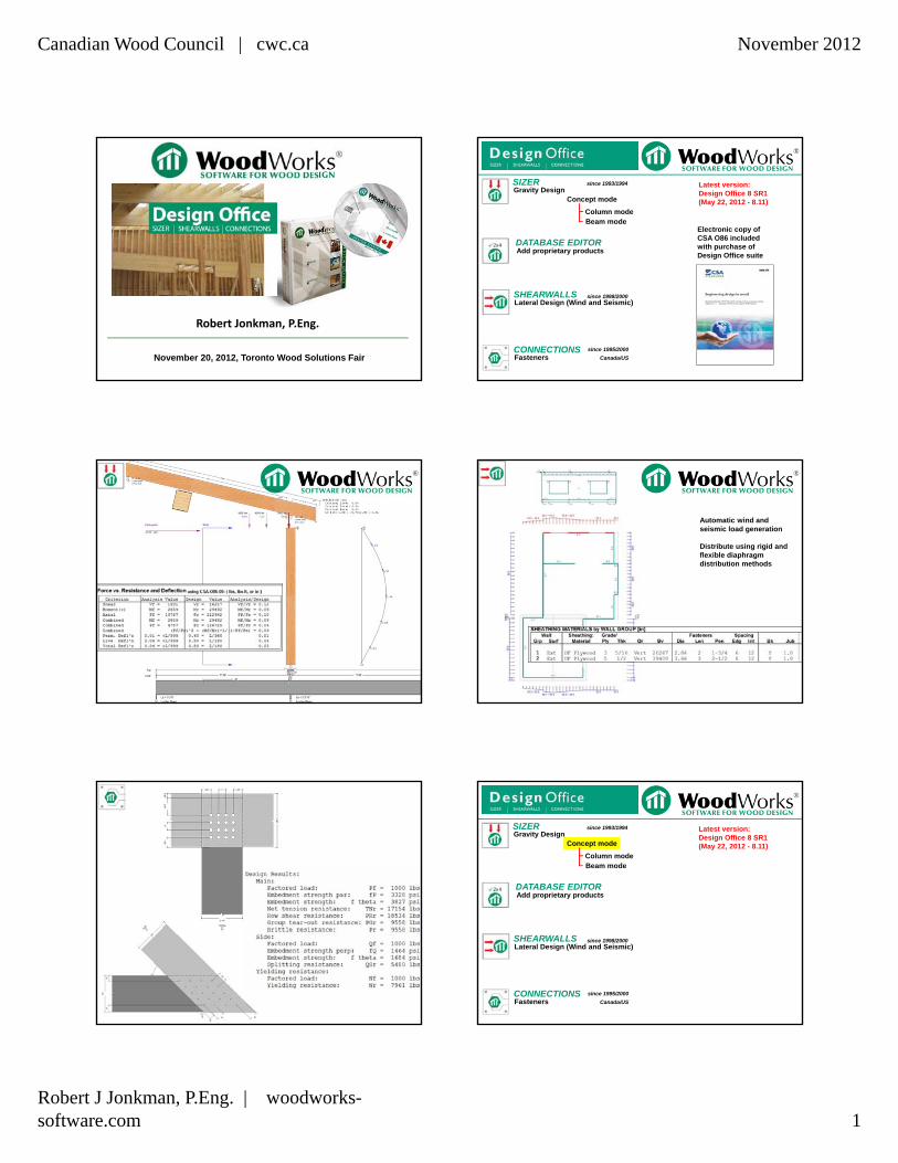
Robert Jonkman, P.Eng.
November 20, 2012, Toronto Wood Solutions Fair
SHEARWALLS
CONNECTIONS
SIZERGravity Design
Lateral Design (Wind and Seismic)
Fasteners
Concept mode
Beam modeColumn mode
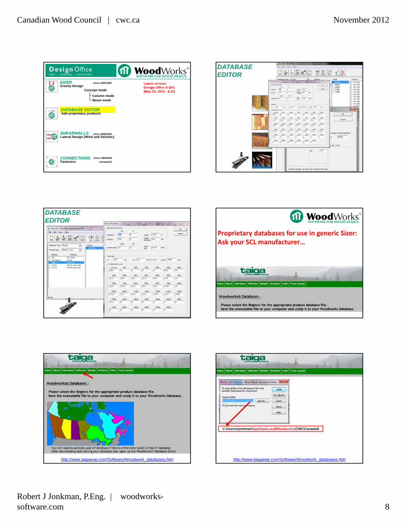
DATABASE EDITOR
since 1993/1994
since 1998/2000
since 1995/2000
Canada/US
Add proprietary products
Electronic copy of CSA O86 included with purchase of Design Office suite
Latest version:Design Office 8 SR1(May 22, 2012 - 8.11)
Automatic wind and seismic load generation
Distribute using rigid and flexible diaphragm distribution methods
SHEARWALLS
CONNECTIONS
SIZERGravity Design
Lateral Design (Wind and Seismic)
Fasteners
Concept mode
Beam modeColumn mode
DATABASE EDITOR
since 1993/1994
since 1998/2000
since 1995/2000
Canada/US
Add proprietary products
Latest version:Design Office 8 SR1(May 22, 2012 - 8.11)

Canadian Wood Council | cwc.ca November 2012
Robert J Jonkman, P.Eng. | woodworks-software.com 2
SIZER-Concept
Elevation view Plan view
SIZER-Concept
Transfer HIP load information to Beam mode
SIZER-Beam
Transferred Length and Slope to Beam mode
SIZER-Beam
Transferred HIP load info to Beam mode
SIZER-ConceptExample
SIZER-ConceptExample

Canadian Wood Council | cwc.ca November 2012
Robert J Jonkman, P.Eng. | woodworks-software.com 3
SHEARWALLS
CONNECTIONS
SIZERGravity Design
Lateral Design (Wind and Seismic)
Fasteners
Concept mode
Beam modeColumn mode
DATABASE EDITOR
since 1993/1994
since 1998/2000
since 1995/2000
Canada/US
Add proprietary products
Latest version:Design Office 8 SR1(May 22, 2012 - 8.11)
• Simply Supported
• Multi-Span Continuous
• Cantilevers
• Biaxial bending members (such as oblique purlins)
Detailed Design of Beams, Joists, Rafters
SIZER-Beam
SIZER-Beam
Beam input
Size, material, span Details Bearing Support
SIZER-Beam
Beam input
Size, material, span
SIZER-Beam
Size, material, span
SIZER-Beam Span type: Design, Clear, Full
Design span: centre to centre of bearingClear: inside to inside of bearingFull: outside to outside of bearing
Canadian Wood Council | cwc.ca November 2012
Robert J Jonkman, P.Eng. | woodworks-software.com 4
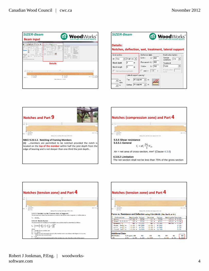
SIZER-Beam
Beam input
Details
SIZER-Beam
Details:Notches, deflection, wet, treatment, lateral support
NBCC 9.23.5.2. Notching of Framing Members(1) …members are permitted to be notched provided the notch islocated on the top of the member within half the joist depth from theedge of bearing and is not deeper than one‐third the joist depth…
Notches and Part 9 Notches (compression zone) and Part 4
5.5.5 Shear resistance5.5.5.1 General
An = net area of cross-section, mm2 (Clause 4.3.8)
4.3.8.2 LimitationThe net section shall not be less than 75% of the gross section
Notches (tension zone) and Part 4 Notches (tension zone) and Part 4
Canadian Wood Council | cwc.ca November 2012
Robert J Jonkman, P.Eng. | woodworks-software.com 5
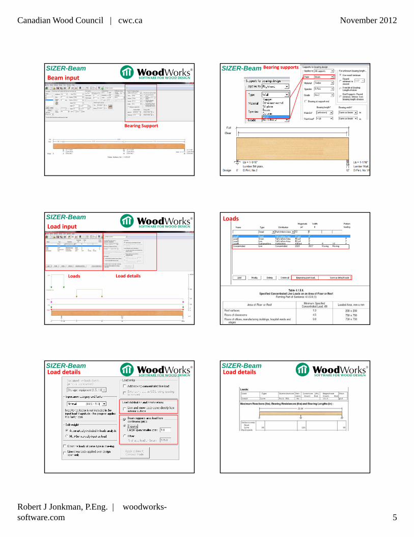
SIZER-Beam
Beam input
Bearing Support
SIZER-Beam Bearing supports
SIZER-Beam
Load input
Loads Load details
Loads
SIZER-BeamLoad details
SIZER-BeamLoad details
Canadian Wood Council | cwc.ca November 2012
Robert J Jonkman, P.Eng. | woodworks-software.com 6
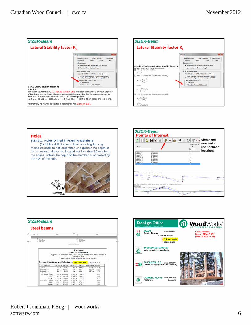
Lateral Stability factor KL
5.5.4.2 Lateral stability factor, KL5.5.4.2.1The lateral stability factor, KL , may be taken as unity when lateral support is provided at points of bearing to prevent lateral displacement and rotation, provided that the maximum depth-to-width ratio of the member does not exceed the following values:(a) 4:1 … (b) 5:1 … (c) 6.5:1… (d) 7.5:1 or… (e) 9:1 if both edges are held in line.
Alternatively, KL may be calculated in accordance with Clause 6.5.6.4.
SIZER-Beam
Lateral Stability factor KL
SIZER-Beam
Holes9.23.5.1. Holes Drilled in Framing Members
(1) Holes drilled in roof, floor or ceiling framing members shall be not larger than one-quarter the depth of the member and shall be located not less than 50 mm from the edges, unless the depth of the member is increased by the size of the hole.
Shear and moment at user-defined locations
Points of InterestSIZER-Beam
Steel beams
SIZER-Beam
2009 CSA-S16-09 SHEARWALLS
CONNECTIONS
SIZERGravity Design
Lateral Design (Wind and Seismic)
Fasteners
Concept mode
Beam modeColumn mode
DATABASE EDITOR
since 1993/1994
since 1998/2000
since 1995/2000
Canada/US
Add proprietary products
Latest version:Design Office 8 SR1(May 22, 2012 - 8.11)

Canadian Wood Council | cwc.ca November 2012
Robert J Jonkman, P.Eng. | woodworks-software.com 7
• Columns & Walls
• Eccentric loading
• Compression & Tension
• Axial / Lateral Loads
• Fixed or Pinned
SIZER-Column SIZER-Column
Eccentric Loads
SIZER-Column
Fixed or Pinned BaseFull support, unbraced, or specify distance
SIZER-Column
Load face can be the width or depth of columns or studs
Links to Sizer: Links to Sizer:
Canadian Wood Council | cwc.ca November 2012
Robert J Jonkman, P.Eng. | woodworks-software.com 8
SHEARWALLS
CONNECTIONS
SIZERGravity Design
Lateral Design (Wind and Seismic)
Fasteners
Concept mode
Beam modeColumn mode
DATABASE EDITOR
since 1993/1994
since 1998/2000
since 1995/2000
Canada/US
Add proprietary products
Latest version:Design Office 8 SR1(May 22, 2012 - 8.11)
DATABASE EDITOR
DATABASE EDITOR
Proprietary databases for use in generic Sizer:Ask your SCL manufacturer…
http://www.taigaewp.com/Software/Woodwork_databases.htm http://www.taigaewp.com/Software/Woodwork_databases.htm
C:\Users\rjonkman\AppData\Local\Woodworks\CWC\Canada\8

Canadian Wood Council | cwc.ca November 2012
Robert J Jonkman, P.Eng. | woodworks-software.com 9
http://www.taigaewp.com/Software/Woodwork_databases.htm http://www.taigaewp.com/Software/Woodwork_databases.htm
Custom versions of Sizer:
SHEARWALLS
CONNECTIONS
SIZERGravity Design
Lateral Design (Wind and Seismic)
Fasteners
Concept mode
Beam modeColumn mode
DATABASE EDITOR
since 1993/1994
since 1998/2000
since 1995/2000
Canada/US
Add proprietary products
Latest version:Design Office 8 SR1(May 22, 2012 - 8.11)

Canadian Wood Council | cwc.ca November 2012
Robert J Jonkman, P.Eng. | woodworks-software.com 10
Automatic Wind and Seismic Load Generation:
Enter city OR
Enter reference information from Building code
Additional loads can be added manually
SHEARWALLS SHEARWALLS
Distributes the automatically generated loads to each shear wall
Designs for wind suction
Designs for shear
Rigid diaphragm(Stiffness)
Flexible diaphragm(Tributary area)
CAD Import in Windows Metafile format (.wmf)
SHEARWALLS(.pdf coming next version)
• Traditional Holddowns each Segment
• Some or all Hold-downs omitted, anchorage used –rely on sheathing transferring tension
Hold-downs
OR
SHEARWALLS
Demo: Basics of shearwalls• Example.wmf template
• Manual load addition
• Automatic load generation based on location
• Log file additional calculations
• .wmf (windows metafile)
• Single wall check
• Timesaver: specify complete wall to reduce wall types, show failed wall
• Dragstrut, hold downs
• Ignore GWB for seismic, Rd = 3 or 2
• C&C check
• Wind design method (I7 or I15).
SHEARWALLS
Design tab: Wind design code options
Canadian Wood Council | cwc.ca November 2012
Robert J Jonkman, P.Eng. | woodworks-software.com 11
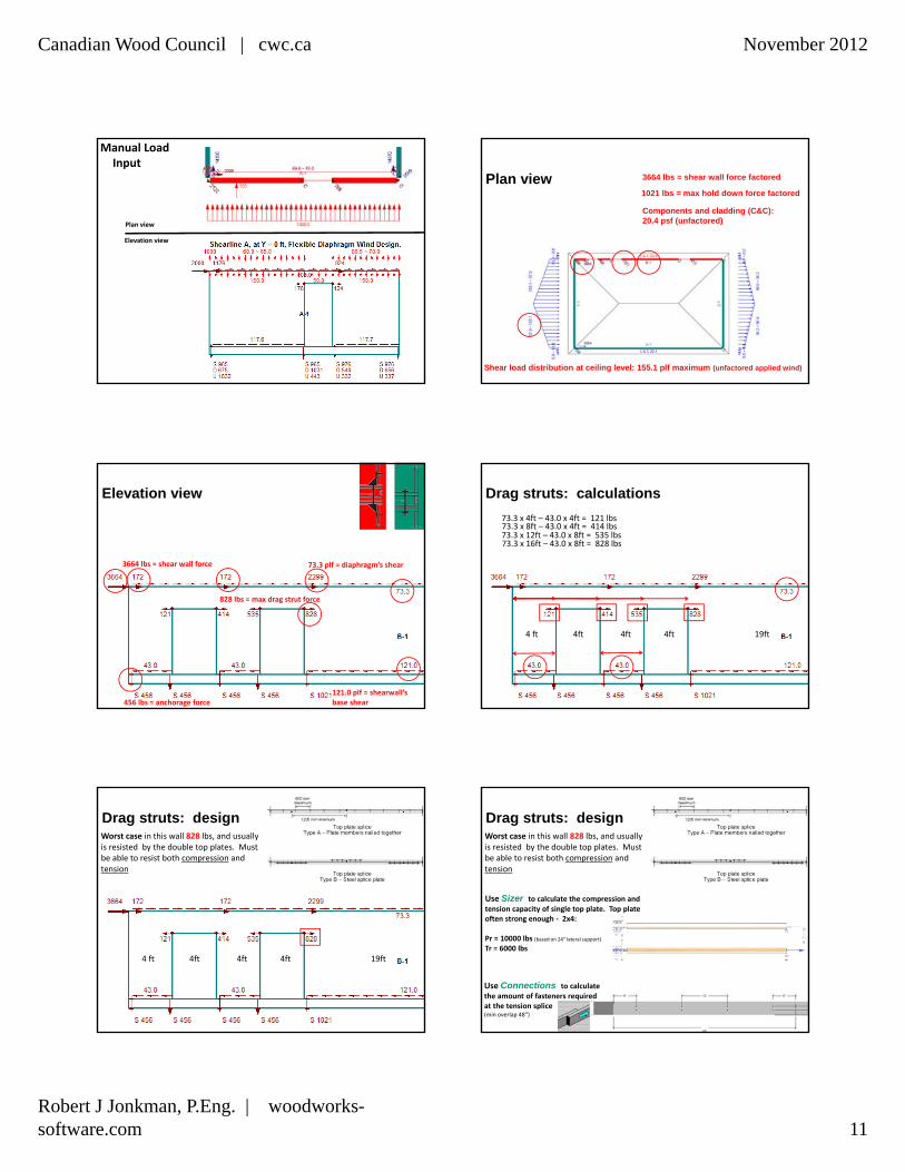
Manual Load Input
Plan view
Elevation view
Plan view
Components and cladding (C&C): 20.4 psf (unfactored)
3664 lbs = shear wall force factored
Shear load distribution at ceiling level: 155.1 plf maximum (unfactored applied wind)
1021 lbs = max hold down force factored
Elevation view
73.3 plf = diaphragm’s shear
121.0 plf = shearwall’sbase shear
3664 lbs = shear wall force
828 lbs = max drag strut force
456 lbs = anchorage force
Drag struts: calculations
73.3 x 4ft – 43.0 x 4ft = 121 lbs
4 ft 4ft 4ft 4ft 19ft
73.3 x 8ft – 43.0 x 4ft = 414 lbs73.3 x 12ft – 43.0 x 8ft = 535 lbs73.3 x 16ft – 43.0 x 8ft = 828 lbs
Drag struts: design
4 ft 4ft 4ft 4ft 19ft
Worst case in this wall 828 lbs, and usually is resisted by the double top plates. Must be able to resist both compression and tension
Drag struts: designWorst case in this wall 828 lbs, and usually is resisted by the double top plates. Must be able to resist both compression and tension
Use Sizer to calculate the compression and tension capacity of single top plate. Top plate often strong enough ‐ 2x4:
Pr = 10000 lbs (based on 24” lateral support)Tr = 6000 lbs
Use Connections to calculate the amount of fasteners required at the tension splice(min overlap 48”)

Canadian Wood Council | cwc.ca November 2012
Robert J Jonkman, P.Eng. | woodworks-software.com 12
Shearwall schedule:
SHEARWALLS
Equations ‐ see .log file
SHEARWALLS
Equations ‐ see .log file
SHEARWALLS
Results in Word:
Wall Sheathing: Grade/ Fasteners Spacing
Grp Surf Material Ply Thk Or Bv Dia Len Pen
Edg Int Bk Jub #
1 Ext DF Plywood 3 7.5 Horz 4600 2.84 2 43 150 300 Y 1.0
1 Int GWB - 12.5 Horz 7005 - 1-1/2 26 200 300 Y 1.0 10
2 Both GWB - 12.5 Horz 7005 - 1-1/4 19 150 300 Y 1.0 10
3 Both GWB - 15.9 Horz 7005 - 2-1/4 41 150 300 Y 1.0 10
SHEATHING MATERIALS by WALL GROUP [mm]
Demo: JhdRemoving holddowns using anchorage• See p456 (WDM 2010) - WDM Final.wsw
• Demonstrate Jhd
Hold‐down Effect Factor Jhd
CSA O86 ‐ 9.4.5
Jhd basically states that the strength reduction is a function of ‐ the height of the shearwall, ‐ the lengths of the shearwalls, ‐ the overturning restraint force,‐ the basic shear capacity.
Canadian Wood Council | cwc.ca November 2012
Robert J Jonkman, P.Eng. | woodworks-software.com 13
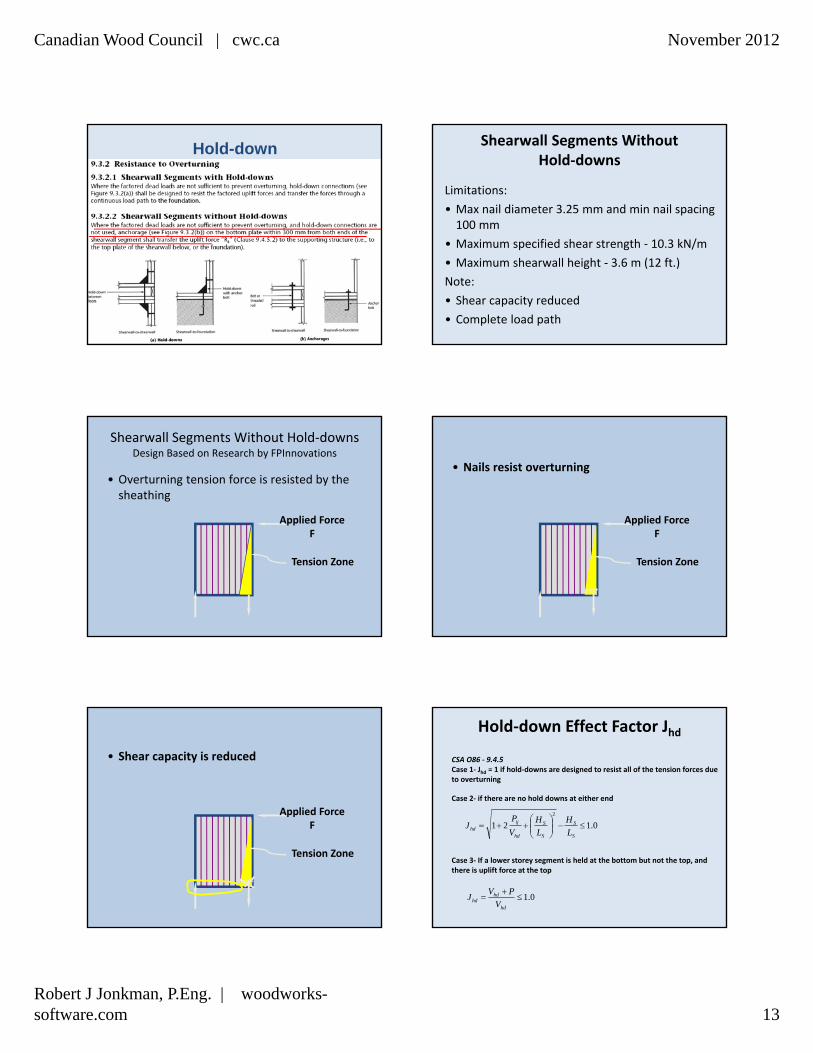
Hold-down Shearwall Segments Without Hold‐downs
Limitations:
• Max nail diameter 3.25 mm and min nail spacing 100 mm
• Maximum specified shear strength ‐ 10.3 kN/m
• Maximum shearwall height ‐ 3.6 m (12 ft.)
Note:
• Shear capacity reduced
• Complete load path
Shearwall Segments Without Hold‐downsDesign Based on Research by FPInnovations
• Overturning tension force is resisted by the sheathing
Applied ForceF
Tension Zone
• Nails resist overturning
Applied ForceF
Tension Zone
• Shear capacity is reduced
Applied ForceF
Tension Zone
CSA O86 ‐ 9.4.5Case 1‐ Jhd = 1 if hold‐downs are designed to resist all of the tension forces due to overturning
0.121
2
S
S
S
S
hd
ijhd L
H
L
H
V
PJ
Case 3‐ If a lower storey segment is held at the bottom but not the top, and there is uplift force at the top
0.1
hd
hdhd V
PVJ
Hold‐down Effect Factor Jhd
Case 2‐ if there are no hold downs at either end
Canadian Wood Council | cwc.ca November 2012
Robert J Jonkman, P.Eng. | woodworks-software.com 14
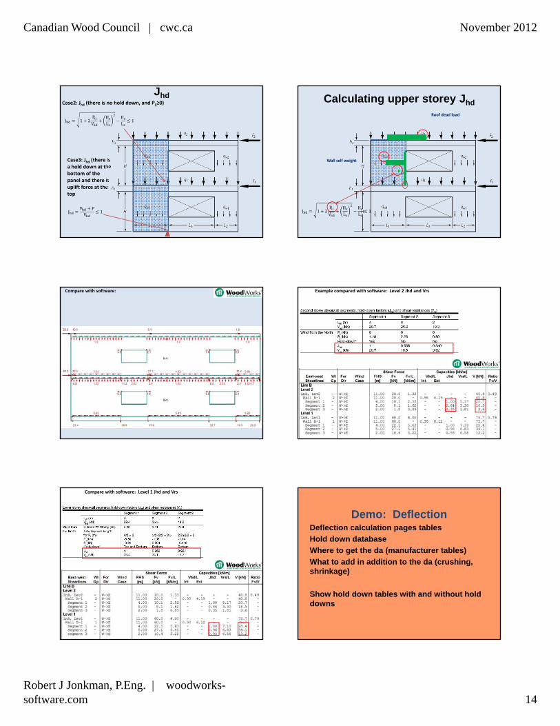
JhdCase2: Jhd (there is no hold down, and Pij≥0)
Case3: Jhd (there is a hold down at the bottom of the panel and there is uplift force at the top
J 1 2P
VHL
HL
1
JV PV
1
Calculating upper storey Jhd
Roof dead load
Wall self weight
P21
J 1 2P
VHL
HL
1
Compare with software: Example compared with software: Level 2 Jhd and Vrs
Compare with software: Level 1 Jhd and Vrs
Demo: DeflectionDeflection calculation pages tables
Hold down database
Where to get the da (manufacturer tables)
What to add in addition to the da (crushing, shrinkage)
Show hold down tables with and without hold downs
Canadian Wood Council | cwc.ca November 2012
Robert J Jonkman, P.Eng. | woodworks-software.com 15
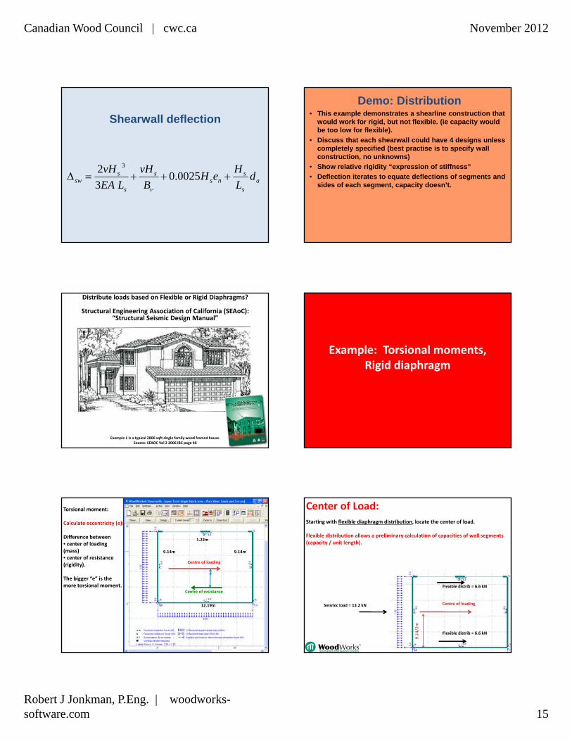
Shearwall deflection
as
sns
s
s
ssw d
L
HeH
B
vH
LEA
vH 0025.0
3
2 3
Demo: Distribution• This example demonstrates a shearline construction that
would work for rigid, but not flexible. (ie capacity would be too low for flexible).
• Discuss that each shearwall could have 4 designs unless completely specified (best practise is to specify wall construction, no unknowns)
• Show relative rigidity “expression of stiffness”
• Deflection iterates to equate deflections of segments and sides of each segment, capacity doesn’t.
Example 1 is a typical 2800 sqft single family wood framed house. Source: SEAOC Vol 2 2006 IBC page 46
Distribute loads based on Flexible or Rigid Diaphragms?
Structural Engineering Association of California (SEAoC):“Structural Seismic Design Manual”
Example: Torsional moments, Rigid diaphragm
Torsional moment:
Calculate eccentricity (e):
Difference between• center of loading (mass) • center of resistance (rigidity).
The bigger “e” is the more torsional moment.
12.19m
1.22m
Centre of loading
9.14m 9.14m
e
Centre of resistance
Center of Load:Starting with flexible diaphragm distribution, locate the center of load.
Flexible distribution allows a preliminary calculation of capacities of wall segments (capacity / unit length).
Centre of loading
Flexible distrib = 6.6 kN
Flexible distrib = 6.6 kN
Seismic load = 13.2 kN
9.14/2m
Canadian Wood Council | cwc.ca November 2012
Robert J Jonkman, P.Eng. | woodworks-software.com 16
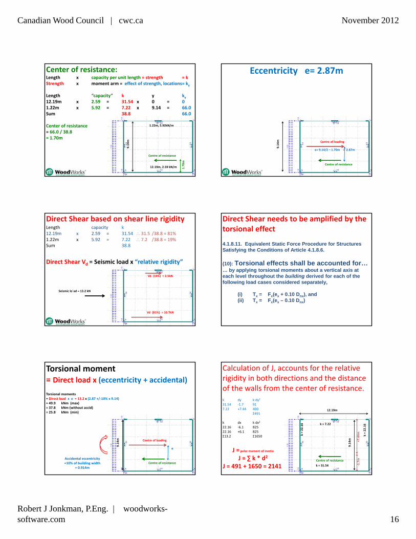
Center of resistance:Length x capacity per unit length = strength = kStrength x moment arm = effect of strength, locations= ky
Length “capacity” k y ky12.19m x 2.59 = 31.54 x 0 = 01.22m x 5.92 = 7.22 x 9.14 = 66.0Sum 38.8 66.0
Center of resistance= 66.0 / 38.8= 1.70m
Centre of resistance
12.19m, 2.59 kN/m
1.22m, 5.92kN/m 9.14m
1.70m
Centre of loading
e= 9.14/2 – 1.70m = 2.87m
Eccentricity e= 2.87m
Centre of resistance
9.14m
Direct Shear based on shear line rigidity
Direct Shear Vd = Seismic load x “relative rigidity”
Seismic lo`ad = 13.2 kN
Vd (81%) = 10.7kN
Vd (19%) = 2.5kN
Length capacity k12.19m x 2.59 = 31.54 31.5 /38.8 = 81%1.22m x 5.92 = 7.22 7.2 /38.8 = 19%Sum 38.8 4.1.8.11. Equivalent Static Force Procedure for Structures
Satisfying the Conditions of Article 4.1.8.6.
(10): Torsional effects shall be accounted for… … by applying torsional moments about a vertical axis at each level throughout the building derived for each of the following load cases considered separately,
(i) Tx = Fx(ex + 0.10 Dnx), and(ii) Tx = Fx(ex – 0.10 Dnx)
Direct Shear needs to be amplified by the torsional effect
Accidental eccentricity =10% of building width
= 0.914m
Torsional moments= Direct load x e = 13.2 x (2.87 +/‐10% x 9.14) = 49.9 kNm (max)= 37.8 kNm (without accid)= 25.8 kNm (min)
Torsional moment= Direct load x (eccentricity + accidental)
Centre of loading
e
9.14m
Centre of resistance
Calculation of J, accounts for the relative rigidity in both directions and the distance of the walls from the center of resistance. k dy k dy2
31.54 ‐1.7 917.22 +7.44 400
Σ491
k dx k dx2
22.16 ‐6.1 82522.16 +6.1 825Σ13.2 Σ1650
k = 31.54
k = 7.22
9.14m
‐1.7m
+7.44mk = 22.16
k = 22.16
J = polar moment of inertia
J = ∑ k * d2
J = 491 + 1650 = 2141
12.19m
Centre of resistance
Canadian Wood Council | cwc.ca November 2012
Robert J Jonkman, P.Eng. | woodworks-software.com 17
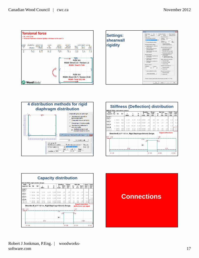
FLEX: 6.6RIGID: Direct 2.5 + Torsion 1.2
RIGID: Total 3.7 kN
Torsional force= MT x kd / ∑ kd= Torsional moment x relative rigidity x distance to the wall / J
FLEX: 6.6RIGID: Direct 10.7 + Torsion (‐0.6)
RIGID: Total 10.1 kN
Settings: shearwallrigidity
4 distribution methods for rigid diaphragm distribution
Stiffness (Deflection) distribution
Equal deflections
Capacity distribution
Equal capacities, deflections not equal
Connections

Canadian Wood Council | cwc.ca November 2012
Robert J Jonkman, P.Eng. | woodworks-software.com 18
SHEARWALLS
CONNECTIONS
SIZERGravity Design
Lateral Design (Wind and Seismic)
Fasteners
Concept mode
Beam modeColumn mode
DATABASE EDITOR
since 1993/1994
since 1998/2000
since 1995/2000
Canada/US
Add proprietary products
Latest version:Design Office 8 SR1(May 22, 2012 - 8.11)
• Beam to Beam
• Beam to column
• Column to base
• Wood to wood, concrete or steel
P
P
P
P
CONNECTIONS
CONNECTIONS
Connections and associated Fasteners on first screen
CONNECTIONSDetails are all displayed in one view
• Fully dimensioned CAD-like drawings• Some connections export as .dxf
CONNECTIONS
Beam to beam
Some connections export as .dxf
Beam to beam

Canadian Wood Council | cwc.ca November 2012
Robert J Jonkman, P.Eng. | woodworks-software.com 19
Bolts 10.4
Wood Screws 10.11
CONNECTIONS Bolt Design 2009 CSA O86Parallel-to-
grain
Brittle
Perpendicular-to-grain
All loading directions
Bolt Yielding
Source: FP Innovations - Forintek
Bolt Design 2009 CSA O86 Yielding
Bolt Yielding
Mode gMode c Mode d
Source: Université Laval, 2009
Row Shear
Source: FP Innovations - Forintek
Canadian Wood Council | cwc.ca November 2012
Robert J Jonkman, P.Eng. | woodworks-software.com 20
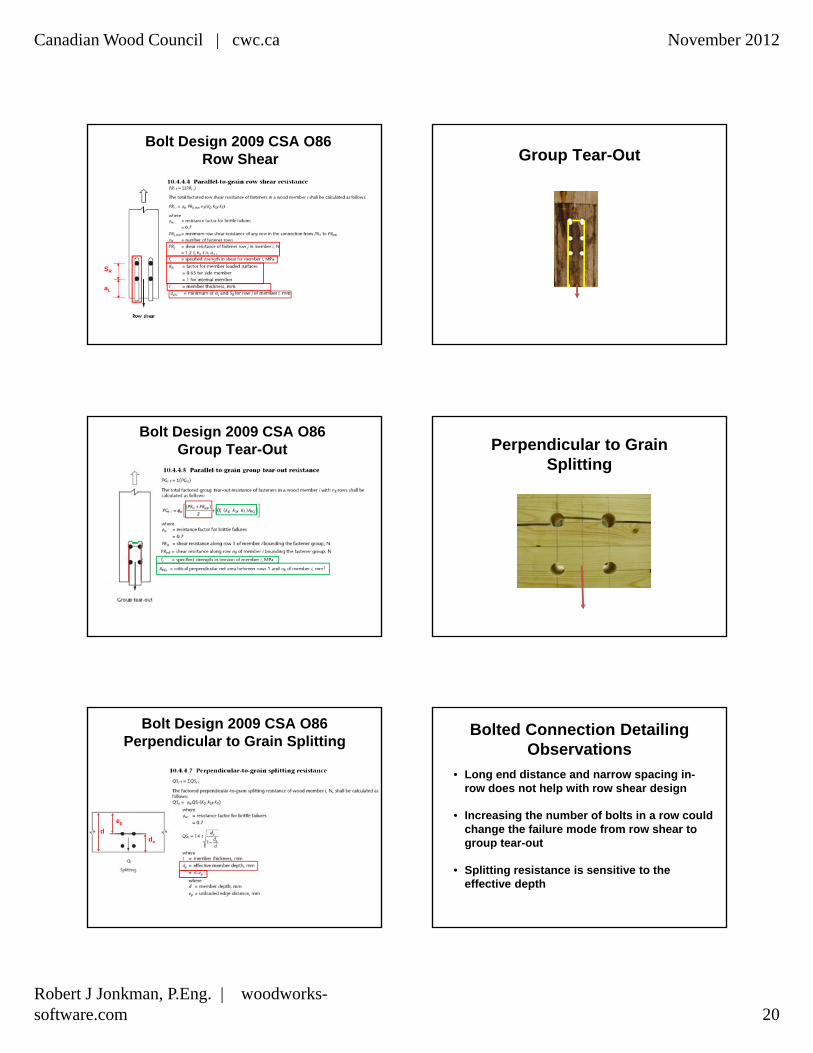
Bolt Design 2009 CSA O86Row Shear
aL
SR
Group Tear-Out
Source: FP Innovations - Forintek
Bolt Design 2009 CSA O86Group Tear-Out Perpendicular to Grain
Splitting
Source: FP Innovations - Forintek
Bolt Design 2009 CSA O86Perpendicular to Grain Splitting
de
d
ep
Bolted Connection Detailing Observations
• Long end distance and narrow spacing in-row does not help with row shear design
• Increasing the number of bolts in a row could change the failure mode from row shear to group tear-out
• Splitting resistance is sensitive to the effective depth

Canadian Wood Council | cwc.ca November 2012
Robert J Jonkman, P.Eng. | woodworks-software.com 21
Brittle failure possible
Ductile failuregoverns
Purchase online:
woodworks-software.com
Design Office: $895Sizer: $295
Discounts for multi-seat purchasesDiscounts for upgrades
($805) ($266)