roadmap on 3d integral imaging: sensing, processing, and
TRANSCRIPT

Research Article Vol. 28, No. 22 / 26 October 2020 / Optics Express 32266
Roadmap on 3D integral imaging: sensing,processing, and display
BAHRAM JAVIDI,1,* ARTUR CARNICER,2 JUN ARAI,3 TOSHIAKIFUJII,4 HONG HUA,5 HONGEN LIAO,6 MANUELMARTÍNEZ-CORRAL,7 FILIBERTO PLA,8 ADRIAN STERN,9
LAURA WALLER,10 QIONG-HUA WANG,11 GORDON WETZSTEIN,12
MASAHIRO YAMAGUCHI,13 AND HIROTSUGU YAMAMOTO14,15
1Department of Electrical and Computer Engineering, University of Connecticut, Storrs, CT 06269, USA2Universitat de Barcelona (UB), Departament de Física Aplicada, Martí i Franqués 1, 08028 Barcelona,Catalonia, Spain3Science and Technology Research Laboratories, NHK (Japan Broadcasting Corporation), 1-10-11 Kinuta,Setagaya-ku, Tokyo 1578510, Japan4Department of Information and Communication, Nagoya University, Furo-cho, Chikusa-ku, Nagoya, Aichi464-8603, Japan53D Visualization and Imaging System Laboratory, James C. Wyant College of Optical Sciences, TheUniversity of Arizona, 1630 E. University Blvd., Tucson, Arizona 85721, USA6Department of Biomedical Engineering, School of Medicine, Tsinghua University, Beijing 100084, China73D Imaging and Display (3DID) Lab., Department of Optics, University of Valencia. E46100 Burjassot,Spain8Institute of New Imaging Technologies, University Jaume I, Castellón 12071, Spain9School of Electrical and Computer Engineering, Ben-Gurion University of the Negev, P.O.B. 653,Beer-Sheva 8410501, Israel10Department of Electrical Engineering and Computer Sciences, UC Berkeley, Berkeley, CA 94720, USA11School of Instrumentation and Optoelectronic Engineering, Beihang University, Beijing 100191, China12Department of Electrical Engineering, Stanford University, 350 Jane Stanford Way, Stanford, CA 94305,USA13School of Engineering, Tokyo Institute of Technology, 4259-G2-28 Nagatsuta, Midori-ku, Yokohama226-8503, Japan14Center for Optical Research and Education (CORE), Utsunomiya University, Yoto 7-1-2, UtsunomiyaCity, Tochigi 3210904, Japan15JST, ACCEL, Yoto 7-1-2, Utsunomiya City, Tochigi 3210904, Japan*[email protected]
Abstract: This Roadmap article on three-dimensional integral imaging provides an overviewof some of the research activities in the field of integral imaging. The article discusses variousaspects of the field including sensing of 3D scenes, processing of captured information, and3D display and visualization of information. The paper consists of a series of 15 sections fromthe experts presenting various aspects of the field on sensing, processing, displays, augmentedreality, microscopy, object recognition, and other applications. Each section represents the visionof its author to describe the progress, potential, vision, and challenging issues in this field.
© 2020 Optical Society of America under the terms of the OSA Open Access Publishing Agreement
1. Introduction
The interest in investigation, research, development, and commercialization of three dimensional(3D) technologies extends well over 150 years with the introduction of stereoscopy, and it is asold as the invention of photography. 3D activities are mainly divided between the scene capture,data processing, and visualization and display of 3D information. The 3D field is very broad andthe application areas include commercial electronics, entertainment, manufacturing, autonomous
#402193 https://doi.org/10.1364/OE.402193Journal © 2020 Received 6 Jul 2020; revised 25 Aug 2020; accepted 27 Aug 2020; published 12 Oct 2020
Research Article Vol. 28, No. 22 / 26 October 2020 / Optics Express 32267
driving, augmented reality, security and defense, biomedicine, etc. The 3D technologies researchand development activities are conducted in academia, industry, and government Labs, andthey have been implemented for objects from macro to micro scales. The broad scope of theseactivities is reflected in the large number of publications, conferences, and seminars, and industrialactivities in the 3D field conducted across the globe in many international organizations.
Integral imaging is one of the several approaches used to implement 3D technologies [1–29].Initially, it was invented by Lippman [1] who named it Integral Photography and later won theNobel prize in physics for his inventions. The pioneering work of a number of researchers[5–9] in the 1970s, 80s, and 90s rejuvenated the interest in this 3D field. In recent years, this3D approach is referred to as integral imaging since a digital camera is used for scene captureand spatial light modulators are used for display instead of photographic film. In addition tointegral imaging terminology, this approach has been named as plenoptics [19,20], and lightfield[21,23]. Integral imaging is an attractive approach because it is a passive imaging system, and itcan operate in outdoor scenes, and under incoherent or ambient light for important applications[2–29].
This roadmap paper on 3D Integral Imaging: Sensing, Processing, and Display is intended toprovide an overview of research activities in the broad field of integral imaging. This roadmapwill consist of a series of 15 sections from the experts presenting various aspects of integralimaging, including sensing, processing, microscopy, biomedicine, object recognition, displays,and augmented reality. Each section represents the vision of its author to describe the progress,potential, applications, and challenging issues in this field. The contributions are ordered asfollows (Table 1):
Table 1. Paper sections
Sensing and processingSection 2: Optical signal detection in turbid water by multidimensional integral imaging
Section 3: Low light 3D object visualization and recognition with visible range image sensors
Section 4: Polarimetric measurements with integral imaging
Section 5: Integral microscopy
Section 6: DiffuserCam: a new method for single-shot 3D microscopy
Section 7: Data compression and coding of the integral imaging data
Section 8: Hand gesture recognition using a 3D sensing approach based on integral imaging
DisplaySection 9: Perceivable light fields for integral imaging display design
Section 10: Towards the development of high-quality three-dimensional displays
Section 11: On the duality of light field imaging and display
Section 12: Progress overview on head-mounted light field displays
Section 13: Innovation of 3D integral imaging display and AR for biomedicine
Section 14: Tabletop integral imaging 3D display
Section 15: Aerial display
Section 16: Spatial displays for 3D human interface by integral and holographic imaging technologies
The three first sections analyze problems related with the detection of signals in turbid mediausing multiple light sources, strategies to record and display of 3D scenes in low light conditionsand the measure of 3D polarimetric information, i.e. Stokes parameters and the Müller matrix,respectively. Sections 5 and 6 describe recent advances in light field microscopy, includingFourier and lens-less approaches in which the micro-lens array is replaced with a diffuser,respectively. In Section 7, we discuss about the necessity of using data compression methods
Research Article Vol. 28, No. 22 / 26 October 2020 / Optics Express 32268
adapted to 3D imaging because of the large amount of data required for the description of thelight field. Section 8 summarizes previous research work on 3D sensing for gesture recognitionbased on integral imaging.Sections 9 to 16 analyze a variety of problems related to 3D displays. In Section 9, we
introduce a technique to calculate the best perceivable light distribution that ideally should beprovided to the viewer, namely the Perceivable Light Field. In Section 10 we discuss how designvariables are selected depending on whether the display is intended for one or multiple users,whereas in section and 11 we analyze trade-off restrictions between angular diversity of light raysand spatial resolution of images. Section 12 provides an overview on head-mounted light fielddisplays, focusing on present designs and future challenges. Applications of integral imaging andartificial vision (AR) for biomedicine are considered in Section 13: the main problems of thesedevices are (i) the trade-off between viewing angle and resolution and (ii) the requirement ofhigh-quality real-time rendering. In Sections 14 and 15 we describe two possible approaches for3D displays: the tabletop which enables vivid and natural 3D visual experience and 360-degreeviewing zone, and the so called aerial display designed to show information in mid-air wherethere is no display hardware, respectively. Finally, in Section 16, we analyze how holography andintegral imaging can be combined as solution of various application challenges. The conclusionsare presented in Section 17.
2. Optical signal detection in turbid water by multidimensional integral imaging
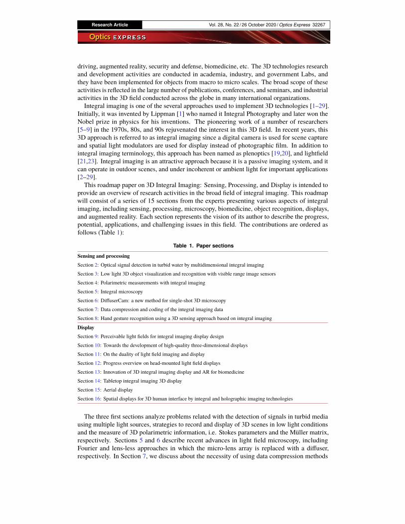
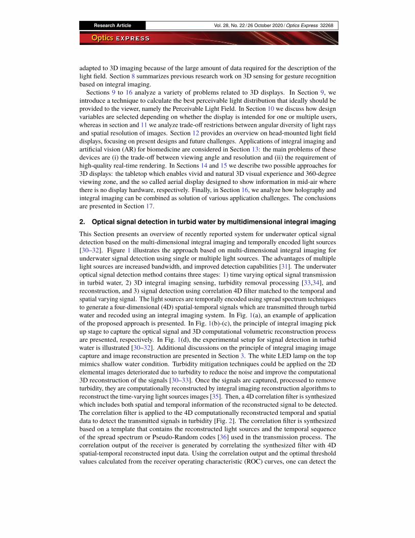
This Section presents an overview of recently reported system for underwater optical signaldetection based on the multi-dimensional integral imaging and temporally encoded light sources[30–32]. Figure 1 illustrates the approach based on multi-dimensional integral imaging forunderwater signal detection using single or multiple light sources. The advantages of multiplelight sources are increased bandwidth, and improved detection capabilities [31]. The underwateroptical signal detection method contains three stages: 1) time varying optical signal transmissionin turbid water, 2) 3D integral imaging sensing, turbidity removal processing [33,34], andreconstruction, and 3) signal detection using correlation 4D filter matched to the temporal andspatial varying signal. The light sources are temporally encoded using spread spectrum techniquesto generate a four-dimensional (4D) spatial-temporal signals which are transmitted through turbidwater and recoded using an integral imaging system. In Fig. 1(a), an example of applicationof the proposed approach is presented. In Fig. 1(b)-(c), the principle of integral imaging pickup stage to capture the optical signal and 3D computational volumetric reconstruction processare presented, respectively. In Fig. 1(d), the experimental setup for signal detection in turbidwater is illustrated [30–32]. Additional discussions on the principle of integral imaging imagecapture and image reconstruction are presented in Section 3. The white LED lamp on the topmimics shallow water condition. Turbidity mitigation techniques could be applied on the 2Delemental images deteriorated due to turbidity to reduce the noise and improve the computational3D reconstruction of the signals [30–33]. Once the signals are captured, processed to removeturbidity, they are computationally reconstructed by integral imaging reconstruction algorithms toreconstruct the time-varying light sources images [35]. Then, a 4D correlation filter is synthesizedwhich includes both spatial and temporal information of the reconstructed signal to be detected.The correlation filter is applied to the 4D computationally reconstructed temporal and spatialdata to detect the transmitted signals in turbidity [Fig. 2]. The correlation filter is synthesizedbased on a template that contains the reconstructed light sources and the temporal sequenceof the spread spectrum or Pseudo-Random codes [36] used in the transmission process. Thecorrelation output of the receiver is generated by correlating the synthesized filter with 4Dspatial-temporal reconstructed input data. Using the correlation output and the optimal thresholdvalues calculated from the receiver operating characteristic (ROC) curves, one can detect the
Research Article Vol. 28, No. 22 / 26 October 2020 / Optics Express 32269
transmitted signals in turbid water [30,31]. In summary, multi-dimensional integral imagingsystems [37] are promising in signal detection in turbid water.
Fig. 1. Multidimensional integral imaging system for underwater signal detection: (a) anexample of transmission and capture of optical signals underwater. (b) illustration of imagecapture stage of integral imaging, (c) computational volumetric reconstruction process forintegral imaging, and (d) experimental setup to capture the optical signal during the pickupstage of integral imaging [30–32].
Fig. 2. Flow chart of the proposed system for (a) optical signal transmission and (b) opticalsignal detection in underwater communication. SS: Spread Spectrum. InIm: IntegralImaging [30–32].
Research Article Vol. 28, No. 22 / 26 October 2020 / Optics Express 32270
3. Low light 3D object visualization and recognition with visible range imagesensors
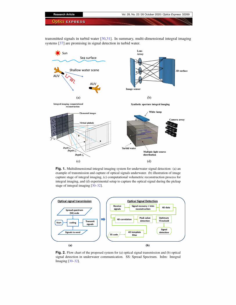
In this Section, we present an overview of 3D integral imaging object visualization and recognitionin very low illumination conditions using visible range image sensors [38,39]. Passive imagingin very low illumination conditions with low cost visible-range image sensors such as CMOSsensors has many applications in manufacturing, remote sensing, night vision, under waterimaging, security and defense, and transportation to name a few. However, this is a challengingproblem mainly due to the read-noise dominant captured images in photon-starved conditions.A simple experiments using conventional 2D imaging with CMOS image sensor in very lowlight scene produces unsatisfactory results with noise like captured images. It has been reportedthat passive 3D integral imaging may perform visualization and recognition under very lowillumination conditions in part because integral imaging reconstruction is optimal in a maximumlikelihood sense under low light conditions [18,38–45]. In addition, 3D integral imaging utilizingconvolutional neural networks can be effective in object recognition in very low illuminationconditions [39]. Integral imaging has been shown to provide superior performance over 2Dimaging in degraded environments [40–45]. Clearly, high-sensitivity image sensors such as EMCCD cameras [44,45] may be used. However, the focus in this section is on 3D low light imagingwith conventional and potentially low cost CMOS image sensors to enable object visualizationand detection in poor illumination conditions. In [38], 3D integral imaging was used in lowillumination for object visualization and detection using a conventional low-cost and compactCMOS sensor. The input scene consisted of a person standing behind an occluding tree branch inlow light (night time). Total Variation (TV) denoising algorithm [46] and the Viola-Jones objectdetection [47] were used to process the reconstructed 3D image which resulted in successful facedetection. Sample experimental results are presented in Figs. 3–4. The photons/pixel estimatesare about 7 and 5.3 for the two light levels [38].
Fig. 3. 3D integral imaging experimental results using CMOS image sensor for a personstanding behind an occluding tree branch for two different low light conditions (top withphotons/pixel=7, and bottom row with photons/pixel=5.3). (a) and (d) are the read noiselimited 2D elemental images for the two low light levels. (b) and (e) are the reconstructed3D images with the faces detected using Viola Jones. (c) and (f) are the 3D reconstructeddetected faces from (b) and (e), respectively, after applying the total variation denoising [40].
Research Article Vol. 28, No. 22 / 26 October 2020 / Optics Express 32271
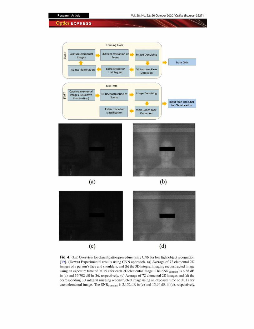
Fig. 4. (Up)Overview for classification procedure usingCNN for low light object recognition[39]. (Down) Experimental results using CNN approach. (a) Average of 72 elemental 2Dimages of a person’s face and shoulders, and (b) the 3D integral imaging reconstructed imageusing an exposure time of 0.015 s for each 2D elemental image. The SNRcontrast is 6.38 dBin (a) and 16.702 dB in (b), respectively. (c) Average of 72 elemental 2D images and (d) thecorresponding 3D integral imaging reconstructed image using an exposure time of 0.01 s foreach elemental image. The SNRcontrast is 2.152 dB in (c) and 15.94 dB in (d), respectively.
Research Article Vol. 28, No. 22 / 26 October 2020 / Optics Express 32272
The experimental results showed increases in the 3D reconstructed image SNR and entropycompared with 2D imaging [38]. The use of convolutional neural networks (CNN) for 3D integralimaging object classification in very low illumination conditions has been reported [39]. TheCNN is trained to perform object recognition on the 3D reconstructed images in different lowillumination conditions and different persons. As in [38], TV denoising is applied to improveSNR and Viola-Jones face detection is used to extract the regions of interest from the denoised3D reconstructed images to be used as input into a CNN for training and testing. The CNNapproach resulted in 100% classification accuracy among 6 subjects in very low illuminationconditions.
4. Polarimetric measurements with integral imaging
The vector character of light fields is not relevant in imaging problems, since the intensityprovides enough information during recording and visualization processes. Nevertheless, the useof the information obtained from the polarization of light is a powerful and convenient tool ofanalysis that can be used in a variety of problems: pattern recognition, machine vision, targetdetection in turbid media, underwater imaging, et cetera [48]. The measure of polarizationrequires several recordings using a linear polarizer and a quarter wave plate. Nowadays severalcompanies commercialize cameras able to determine the Stokes parameters and the degreeof polarization (DoP) in a single shot. The process to generate integral imaging polarimetricdistributions is equivalent to the one used in conventional 2D imaging [49]. A polarizer anda phase plate that determine the required state of polarization (SoP) are located in front of anintegral imaging device. At each shot, the complete set of elementary images corresponding tothe SoP is recorded. Combining these sets in the proper way, the DoP for each elementary imagecan be calculated effortlessly [50,51].
The use of 3D polarimetric techniques is particularly interesting in photon starving conditions.The estimation of the Stokes parameters and the DoP is particularly challenging in conventionalimaging because the signal to noise ratio is very low and numerical errors are spread during thecalculation stage. Note that the estimation of the Stokes parameters involves the difference oftwo intensities and when the number of photons involved is very low, these parameters becomeill-defined resulting in an underestimation of the DoP. Nevertheless, we demonstrated that itis possible to determine the polarimetric information of a scene in low light conditions usingintegral imaging [52]. The reconstruction of the 3D information involves elemental imagesaveraging that might be statistically optimum in maximum likelihood sense [41]. Interestingly,we found that the analysis of the statistical distribution of the DoP provides enough informationto distinguish among areas with strong polarimetric signal and noise [53].
The Stokes parameters characterize the scene for a specific SoP. In particular, if natural light isused, the polarimetric response of the objects can be weak. In contrast, if the scene is illuminatedwith fully polarized light, the signal is stronger but dependent of the illumination SoP. Themeasure of the Müller matrix (MM) provides a complete polarimetric description of the scenefor any SoP of the light source. We recently extended this technique from 2D to 3D imaging [54].Generally speaking, the calculation of the 16 components of the MM requires 36 recordings ofthe light field (six input SoP times six recordings for each input SoP). With this information, it ispossible to derive the MM for each point of the light field. This procedure is time consuming andcan be a disadvantage when the scene is dynamic.
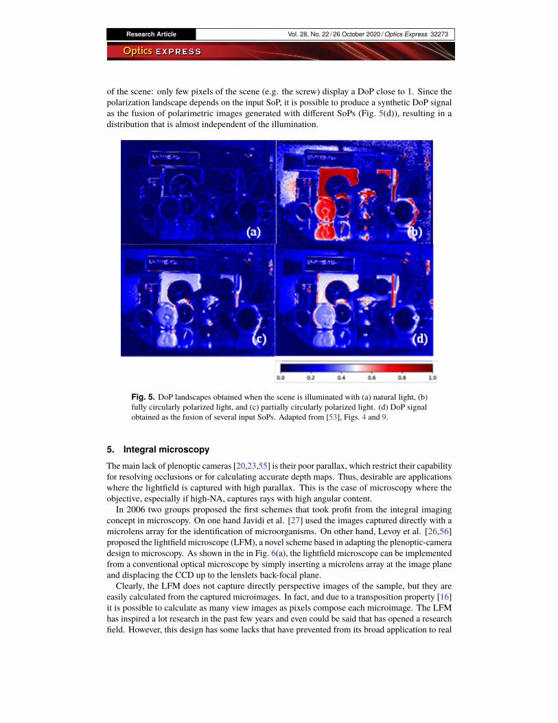
The MM technique is able to display the polarimetric response of the scene for any SoP of theillumination source, including partially polarized light. Fig. 5 shows some DoP results obtainedwith a commercial plenoptic camera (Lytro Illum). The plane that contains the larger clockappears in focus. It is apparent that the polarimetric signal obtained with natural light is veryweak (Fig. 5(a)), whereas large areas of Fig. 5(b), illuminated with fully polarized light, appear tobe saturated. The use of partially polarized light (Fig. 5(c)) provides an equilibrated description
Research Article Vol. 28, No. 22 / 26 October 2020 / Optics Express 32273
of the scene: only few pixels of the scene (e.g. the screw) display a DoP close to 1. Since thepolarization landscape depends on the input SoP, it is possible to produce a synthetic DoP signalas the fusion of polarimetric images generated with different SoPs (Fig. 5(d)), resulting in adistribution that is almost independent of the illumination.
Fig. 5. DoP landscapes obtained when the scene is illuminated with (a) natural light, (b)fully circularly polarized light, and (c) partially circularly polarized light. (d) DoP signalobtained as the fusion of several input SoPs. Adapted from [53], Figs. 4 and 9.
5. Integral microscopy
The main lack of plenoptic cameras [20,23,55] is their poor parallax, which restrict their capabilityfor resolving occlusions or for calculating accurate depth maps. Thus, desirable are applicationswhere the lightfield is captured with high parallax. This is the case of microscopy where theobjective, especially if high-NA, captures rays with high angular content.In 2006 two groups proposed the first schemes that took profit from the integral imaging
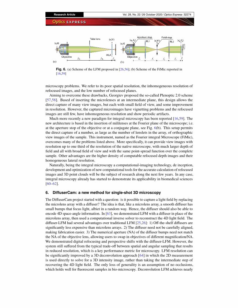
concept in microscopy. On one hand Javidi et al. [27] used the images captured directly with amicrolens array for the identification of microorganisms. On other hand, Levoy et al. [26,56]proposed the lightfield microscope (LFM), a novel scheme based in adapting the plenoptic-cameradesign to microscopy. As shown in the in Fig. 6(a), the lightfield microscope can be implementedfrom a conventional optical microscope by simply inserting a microlens array at the image planeand displacing the CCD up to the lenslets back-focal plane.Clearly, the LFM does not capture directly perspective images of the sample, but they are
easily calculated from the captured microimages. In fact, and due to a transposition property [16]it is possible to calculate as many view images as pixels compose each microimage. The LFMhas inspired a lot research in the past few years and even could be said that has opened a researchfield. However, this design has some lacks that have prevented from its broad application to real
Research Article Vol. 28, No. 22 / 26 October 2020 / Optics Express 32274
Fig. 6. (a) Scheme of the LFM proposed in [26,56]; (b) Scheme of the FiMic reported in[16,59]
microscopy problems. We refer to its poor spatial resolution, the inhomogeneous resolution ofrefocused images, and the low number of refocused planes.
Aiming to overcome these drawbacks, Georgiev proposed the so-called Plenoptic 2.0 scheme[57,58]. Based of inserting the microlenses at an intermediate plane, this design allows thedirect capture of many view images, but each with small field of view, and some improvementin resolution. However, the captured microimages have vignetting problems and the refocusedimages are still few, have inhomogeneous resolution and show periodic artifacts.Much more recently a new paradigm for integral microscopy has been reported [16,59]. The
new architecture is based in the insertion of mililenses at the Fourier plane of the microscope; i.e.at the aperture stop of the objective or at a conjugate plane, see Fig. 6(b). This setup permitsthe direct capture of a number, as large as the number of lenslets in the array, of orthographicview images of the sample. This instrument, named as the Fourier integral Microscope (FiMic),overcomes many of the problems listed above. More specifically, it can provide view images withresolution up to one third of the resolution of the native microscope, with much larger depth offield and all with broad field of view and with the same point-spread function over the completesample. Other advantages are the higher density of computable refocused depth images and theirhomogeneous lateral resolution.Naturally, being the integral microscopy a computational-imaging technology, de inception,
development and optimization of new computational tools for the accurate calculation of refocusedimages and 3D point clouds will be the subject of research along the next few years. In any case,integral microscopy already has started to demonstrate its applicability in biomedical sciences[60–62].
6. DiffuserCam: a new method for single-shot 3D microscopy
The DiffuserCam project started with a question: is it possible to capture a light field by replacingthe microlens array with a diffuser? The idea is that, like a microlens array, a smooth diffuser hassmall bumps that focus light, albiet in a random way. Hence, the diffuser should also be able toencode 4D space-angle information. In [63], we demonstrated LFM with a diffuser in place of themicrolens array, then used a computational inverse solver to reconstruct the 4D light field. Thediffuser-LFM had several advantages over traditional LFM [25,26]: 1) Off-the-shelf diffusers aresignificantly less expensive than microlens arrays. 2) The diffuser need not be carefully aligned,making fabrication easier. 3) The numerical aperture (NA) of the diffuser bumps need not matchthe NA of the objective lens, allowing users to swap in objectives of different magnification/NA.We demonstrated digital refocusing and perspective shifts with the diffuser-LFM. However, thesystem still suffered from the typical trade-off between spatial and angular sampling that resultsin reduced resolution, which is a key performance metric for microscopy. LFM resolution canbe significantly improved by a 3D deconvolution approach [64] in which the 2D measurementis used directly to solve for a 3D intensity image, rather than taking the intermediate step ofrecovering the 4D light field. The only loss of generality is an assumption of no occlusions,which holds well for fluorescent samples in bio-microscopy. Deconvolution LFM achieves nearly
Research Article Vol. 28, No. 22 / 26 October 2020 / Optics Express 32275
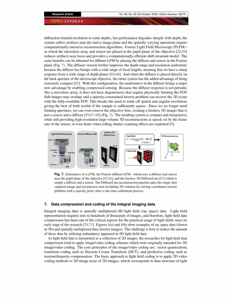
diffraction-limited resolution at some depths, but performance degrades sharply with depth, thesystem suffers artifacts near the native image plane and the spatially-varying operations requirecomputationally-intensive reconstruction algorithms. Fourier Light Field Microscopy (FLFM) -in which the microlens array and sensor are placed at the pupil plane of the objective [28,59]reduces artifacts near focus and provides a computationally-efficient shift-invariant model. Thesame benefits can be obtained for diffuser-LFM by placing the diffuser and sensor in the Fourierplane (Fig. 7). The diffuser version further improves the depth range and resolution uniformitybecause the diffuser has bumps with a wide range of focal lengths, meaning that we have a sharpresponse from a wide range of depth planes [65,66]. And when the diffuser is placed directly onthe back aperture of the microscope objective, the entire system has the added advantage of beingextremely compact [65]. With this configuration, the randomness in the diffuser brings a majornew advantage by enabling compressed sensing. Because the diffuser response is not periodiclike a microlens array, it does not have degeneracies that require physically limiting the FOV.Sub-images may overlap, and a sparsity-constrained inverse problem can recover the 3D scenewith the fully-available FOV. This breaks the need to trade-off spatial and angular resolution,giving the best of both worlds if the sample is sufficiently sparse. Since we no longer needlimiting apertures, we can even remove the objective lens, creating a lensless 3D imager that isjust a sensor and a diffuser [59,67–69] (Fig. 7). The resulting system is compact and inexpensive,while still providing high-resolution large-volume 3D reconstructions at speeds set by the framerate of the sensor, or even faster when rolling shutter scanning effects are exploited [5].
Fig. 7. Schematics of a LFM, the Fourier diffuser-LFM - which uses a diffuser and sensornear the pupil plane of the objective [65,66], and the lensless 3D DiffuserCam [67] which issimply a diffuser and a sensor. The DiffuserCam reconstruction pipeline takes the single-shotcaptured image and reconstructs non-occluding 3D volumes by solving a nonlinear inverseproblem with a sparsity prior, after a one-time calibration process.
7. Data compression and coding of the integral imaging data
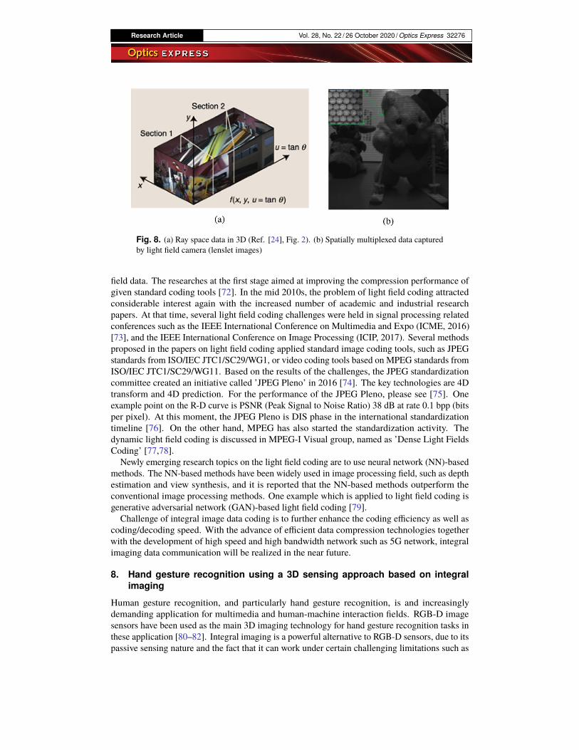
Integral imaging data is spatially multiplexed 4D light field (ray space) data. Light fieldrepresentation requires tens to hundreds of thousands of images, and therefore, light field datacompression has been one of the critical aspects for the practical usage of light fields since itsearly stage of the research [70,71]. Figures 8(a) and 8(b) show examples of ray space data (shownin 3D) and spatially multiplexed data (lenslet images). The challenge is how to reduce the amountof these data by utilizing redundancy appeared in 4D light field data.
As light field data is interpreted as a collection of 2D images, the researches for light field datacompression tried to apply image/video coding schemes which were originally intended for 2Dimage/video coding. The core principles of the image/video coding are: vector quantization,transform coding such as Discrete Cosine Transform (DCT), and predictive coding such asmotion/disparity compensation. The basic approach to light field coding is to apply 2D videocoding methods to 2D image array of 2D images, which corresponds to data structure of light
Research Article Vol. 28, No. 22 / 26 October 2020 / Optics Express 32276
Fig. 8. (a) Ray space data in 3D (Ref. [24], Fig. 2). (b) Spatially multiplexed data capturedby light field camera (lenslet images)
field data. The researches at the first stage aimed at improving the compression performance ofgiven standard coding tools [72]. In the mid 2010s, the problem of light field coding attractedconsiderable interest again with the increased number of academic and industrial researchpapers. At that time, several light field coding challenges were held in signal processing relatedconferences such as the IEEE International Conference on Multimedia and Expo (ICME, 2016)[73], and the IEEE International Conference on Image Processing (ICIP, 2017). Several methodsproposed in the papers on light field coding applied standard image coding tools, such as JPEGstandards from ISO/IEC JTC1/SC29/WG1, or video coding tools based on MPEG standards fromISO/IEC JTC1/SC29/WG11. Based on the results of the challenges, the JPEG standardizationcommittee created an initiative called ’JPEG Pleno’ in 2016 [74]. The key technologies are 4Dtransform and 4D prediction. For the performance of the JPEG Pleno, please see [75]. Oneexample point on the R-D curve is PSNR (Peak Signal to Noise Ratio) 38 dB at rate 0.1 bpp (bitsper pixel). At this moment, the JPEG Pleno is DIS phase in the international standardizationtimeline [76]. On the other hand, MPEG has also started the standardization activity. Thedynamic light field coding is discussed in MPEG-I Visual group, named as ’Dense Light FieldsCoding’ [77,78].
Newly emerging research topics on the light field coding are to use neural network (NN)-basedmethods. The NN-based methods have been widely used in image processing field, such as depthestimation and view synthesis, and it is reported that the NN-based methods outperform theconventional image processing methods. One example which is applied to light field coding isgenerative adversarial network (GAN)-based light field coding [79].
Challenge of integral image data coding is to further enhance the coding efficiency as well ascoding/decoding speed. With the advance of efficient data compression technologies togetherwith the development of high speed and high bandwidth network such as 5G network, integralimaging data communication will be realized in the near future.
8. Hand gesture recognition using a 3D sensing approach based on integralimaging
Human gesture recognition, and particularly hand gesture recognition, is and increasinglydemanding application for multimedia and human-machine interaction fields. RGB-D imagesensors have been used as the main 3D imaging technology for hand gesture recognition tasks inthese application [80–82]. Integral imaging is a powerful alternative to RGB-D sensors, due to itspassive sensing nature and the fact that it can work under certain challenging limitations such as

Research Article Vol. 28, No. 22 / 26 October 2020 / Optics Express 32277
partial occlusion and low illumination conditions. This section summarizes part of the previousresearch work on 3D sensing for gesture recognition based on integral imaging [83,84]. Theseworks showed the capabilities of integral imaging for hand gesture recognition using 3D imagereconstruction techniques that overcome active RGB-D sensors in challenging partial occlusionscenarios. Camera arrays are an integral imaging modality that acquire a set of elemental images,which capture the scene from different viewpoints. High resolution cameras allow to acquireelemental images with larger physical aperture and camera separation, which provide higherimage resolution and better depth estimation within some depth ranges. 3D reconstructionfocusing at a certain depth can be performed from elemental images [51] using computationalmodels based on pinhole arrays [35].Integral imaging from an arrays of cameras can reconstruct the image sequence at the
depth where a hand gesture is located, focusing at the hand movements. The hand gesturemotion is characterized by means of a Bag of Words (BoW) method from previously extractedSpatiotemporal Interest Points (STIPs). These feature points are characterized by extracting localfeatures around the STIPS, which are used to build the BoW characterization that is eventuallyused in a Support Vector Machine (SVM) classifier [83,84]. Experiments were carried outusing a 3x3 camera array for the elemental image acquisition. The integral imaging method wasalso compared with Kinect RGB-D sensor, using the same hand gesture characterization andclassification technique. Image sequences from a single camera were also used as a baselinetechnique. Results showed that integral imaging using an array of cameras outperformed RGB-Dsensing and single image capture particularly in challenging partial occlusion conditions (Fig. 9)[83,84]. Integral imaging provides a variety of potential features that are very adequate forapplication scenarios where challenging conditions, such as partial occlusion, cannot be overcomeby other 3D sensing technologies. Integral imaging capture is a powerful image acquisitiontechnique for passive 3D reconstruction with high image resolution and enough depth estimationaccuracy in certain depth ranges. 3D image reconstruction is a useful tool to extract 3D featuresto characterize and recognize 3D movements such as human hand gestures in multimedia andhuman-machine interaction applications.
Fig. 9. Classification results comparing integral imaging, RGB-D sensing and monocularsensing under partial occlusion conditions [84].

Research Article Vol. 28, No. 22 / 26 October 2020 / Optics Express 32278
9. Perceivable light fields for integral imaging display design
Light Fields (LFs) [70], `(x, y, u, v), are four-dimensional functions representing radiance alongrays as a function of positions (x, y) and the (generalized) directions (u, v). They are commonlyused for the analysis of the propagation of the 3D visual information from the display to theviewer. In [85] we proposed an analysis approach that follows a reversed direction, that is fromthe viewer to the display device, to better evaluate the display device specifications needed tofulfill the viewer requirements. For this purpose, we have introduced the notion of PerceivableLight Field (PLF) [85,86] to describe the best perceivable light distribution that ideally should beprovided to the viewer. The PLF is propagated back to the display device to determine the LFdistribution that the display needs to generate.
One of the main utilities of the LF representation is for analysis of light transport through freespace and through common optical components, because their propagation through first-orderoptical systems can be easily described by simple affine transforms [85,87,88]. For improvedheuristics we proposed in [85] to use a linear decomposition of the LF: ` (x, u) =
∑n,m
ln,mϕn,m (x, u),
where ϕ(x, u) denotes the light field atom (LFA), defined as the most concentrated LF element thata system can support. The PLF is the LF, `(xe, ue), captured and perceived by the human visualsystem. Figure 10(b) illustrates the 2D PLF chart of binocular viewing (Fig. 10(a)). The dots inthe PLF chart in Fig. 10(b) represent the center of the LFAs, according to one possible tilingof the PLF chart [85]. After backpropagation to the integral imaging [17] display (Fig. 10(a)),the PLF is horizontally sheared, `e (xe + zdue, ue), as shown in Fig. 10(c). For high quality 3-Dimage generation, the integral imaging LF support needs to enclose the back-projected PLF, andeach PLF atom should be matched by at least one display LFA.
Fig. 10. (a) Two eyes (right) fixating on an integral imaging display (left), (b) PLF of thetwo eyes. (c) The back propagated PLF to the integral imaging plane overlaid on the integralimaging’s LF chart (α denotes the human visual system resolvable angle, pe denotes the sizeof the eye’s pupil, ϕ is the field of view, and ϕs is the vengeance angle).
In Fig. 10 we considered an integral imaging display working in unfocused mode [17] (a.k.a.resolution priority integral imaging [89] with a static viewer). The same methodology can beused for integral imaging in focused mode, and to include motion parallax as well [85].
Research Article Vol. 28, No. 22 / 26 October 2020 / Optics Express 32279
10. Towards the development of high-quality three-dimensional displays
Since Lippmann’s invention of integral imaging [1], there has been research aimed at developinghigh-quality 3D displays based on this method [2]. In addition, a system for capturing anddisplaying objects as 3D images in real-time has been proposed [7,8,90]. For reconstructinghigh-quality 3D images in real-time, the capture and display devices must have an image sensorand display panel with many fine-pitch pixels along with lens arrays with many fine-pitch lenses.This section presents a recently developed high-resolution 3D display that uses multiple projectorsand a wide-viewing-angle 3D display that utilizes eye-tracking technology.To reconstruct 3D images in integral imaging, the directions of light rays are controlled by
micro-lenses comprising a lens array. Two measures are mainly used to represent the quality ofthe 3D images, i.e., resolution and viewing angle. Moreover, as use-case scenarios in consumerand industry, a 3D display would be viewed by multiple users and individual users.
For multiple users, a 3D display with a large area is preferred; however, it is difficult to fabricatea lens array composed of a lot of micro-lenses covering a large area. Aktina Vision solves thisproblem by controlling the display directions of multi-view images by using a lens larger thanthe micro-lenses [91,92]. In [91], multi-view images consisting of a total of 350 viewpoints areprojected onto a diffusing screen by using fourteen 4K projectors. The resolution of each viewimage is 768(H) x 432(V) pixels, and the viewing angle of the 3D image is 35.1(H) x 4.7(V)degrees. Although the current system is not so compact, Aktina Vision is capable of havinghigher resolution and larger display area by projecting high-resolution multi-view images in alarge area.For individual users, the 3D display area should not be so large. In addition, because it is
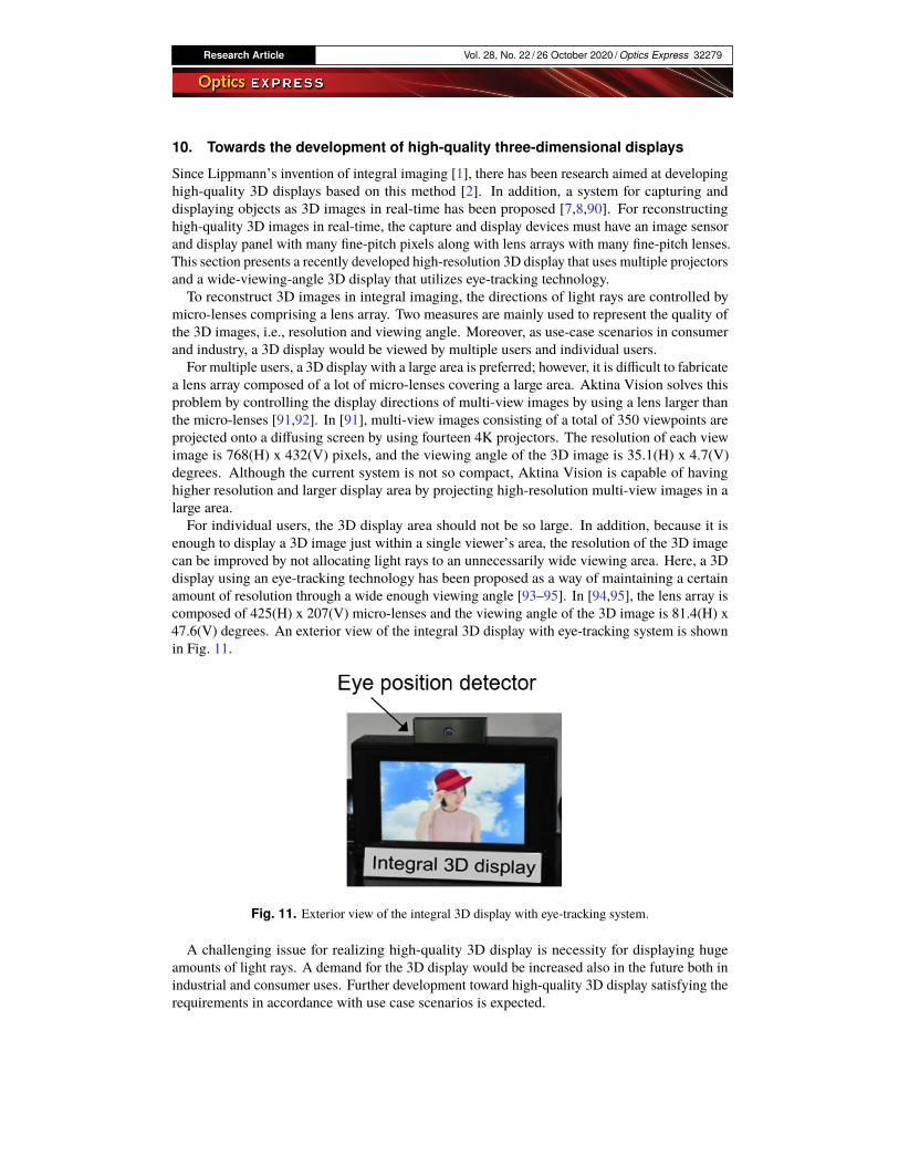
enough to display a 3D image just within a single viewer’s area, the resolution of the 3D imagecan be improved by not allocating light rays to an unnecessarily wide viewing area. Here, a 3Ddisplay using an eye-tracking technology has been proposed as a way of maintaining a certainamount of resolution through a wide enough viewing angle [93–95]. In [94,95], the lens array iscomposed of 425(H) x 207(V) micro-lenses and the viewing angle of the 3D image is 81.4(H) x47.6(V) degrees. An exterior view of the integral 3D display with eye-tracking system is shownin Fig. 11.
Fig. 11. Exterior view of the integral 3D display with eye-tracking system.
A challenging issue for realizing high-quality 3D display is necessity for displaying hugeamounts of light rays. A demand for the 3D display would be increased also in the future both inindustrial and consumer uses. Further development toward high-quality 3D display satisfying therequirements in accordance with use case scenarios is expected.

Research Article Vol. 28, No. 22 / 26 October 2020 / Optics Express 32280
Fig. 12. (Light field processing pipeline. A computational camera system, including one ormore cameras, captures light field data, which is subsequently processed by a neural networkor some other algorithmic framework. The algorithms perform low-level and high-levelimage processing tasks, such as demosaicking and view synthesis, and transmit the data to adirect-view or near-eye light field display
11. On the duality of light field imaging and display
When Gabriel Lippmann invented integral imaging the foundation of most modern light fieldimaging systems he envisioned this technology as a fully integrated imaging and display system[1]. Over the course of the last century, however, an intuitive interpretation of this duality betweencapture and display got lost, mostly because digital and computational approaches to light fieldacquisition and synthesis today have evolved into sophisticated opto-computational systems thatare highly specialized and adapted to specific application domains. This chapter is focused onthe duality between light field capture, processing, and display.Outside the optics community, in the computer vision, graphics, and machine learning
communities, (unstructured) light field capture and view interpolation, extrapolation, andsynthesis have become extremely "hot" topics. Although image-based rendering and conventional3D computer vision have been aiming at reconstructing 3D scenes from 2D images for a long time,emerging neural view synthesis approaches are the first to demonstrate photorealistic quality forthese applications. In addition to these emerging reconstruction and processing approaches, theemergence of virtual reality has created a strong need to capture multiview image and video datafor immersive experiences. In light of this need, custom camera rigs or hand-held camera systemsthat record unstructured light field data have seen much interest. Finally, in the computationaloptics and graphics communities, much work has been done over the last few years on developingnear-eye light field displays for next-generation head-mounted displays. Today, all of theseresearch and engineering efforts on recording, processing, and display light fields are fragmented.In this roadmap article, we argue for a streamlined approach that considers all of these aspectsand potentially optimizes such systems end-to-end from recording photons to displaying themwith a near-eye display (see Fig. 12).
In direct-view displays, light field capabilities enable glasses-free 3D image presentation. Incontrast to conventional 2D displays, such displays provide a richer set of depth cues to the humanvisual system that include binocular disparity and motion parallax in addition to the pictorialcues supported by 2D displays. This capability provides new user experiences in a varietyof applications, such as communication, teleconferencing, entertainment, and visualization.However, one of the biggest challenges of integral imaging-based light field displays and camerasis the spatio-angular resolution tradeoff. In order to provide the angular diversity of lightrays required for light field capture or display with a single device, spatial resolution of the
Research Article Vol. 28, No. 22 / 26 October 2020 / Optics Express 32281
corresponding images typically has to be sacrificed [1–3,23]. This tradeoff is oftentimes notdesirable by a user and may be one of the primary reasons for why neither light field cameras nordisplays have succeeded in the consumer market. Through the co-design of optics, electronics,and algorithms, emerging compressive light field systems provide a modern approach to lightfield imaging and display that have the capability of leveraging redundancy in natural light fielddata to overcome the long-standing spatio-angular resolution tradeoff and enable high spatial andangular light field resolutions simultaneously [96,97].
Over the last decade, virtual and augmented reality (VR/AR) applications have sparked renewedinterest in novel camera and display technologies. In these applications, near-eye light fielddisplays may be able to provide focus cues to a user (e.g., [98]). Focus cues, including retinalblur and accommodation, allow the visual system of non-presbyopic users to accommodate atvarious distances and thus mitigate the vergenceaccommodation conflict in VR/AR. Alternativetechnologies offering similar benefits include gaze-contingent varifocal (e.g., [99,100]) andmultifocal displays (e.g., [101]). Thus, the depth cues supported by light fields in these near-eyedisplay applications are slightly different from direct-view displays, but crucial for visual comfortand perceptual realism. Here too, the duality of light field imaging and display is important,although light field camera systems for VR/AR are primarily used to capture omnidirectionalstereo panoramas (e.g., [102,103]). Such an approach to cinematic VR allows immersive eventsto be captured and later replayed in VR while providing stereoscopic depth cues for 360◦ viewingexperiences.Another emerging research area that provides a strong link between light field capture and
display is neural scene representation and rendering (e.g., [104,105]). Instead of focusingtoo much on camera or display device development, these machine learningdriven methodstake as input one of multiple views of a scene and distill them into a differentiable 3D scenerepresentation, typically a neural network. Such a neural scene representation can then beconverted into 2D images using a neural renderer. This provides a fully differentiable pipelinethat provides state-of-the-art results for view interpolation, hole filling, compression / bandwidthmanagement, and many other problems directly associated with light field imaging and display.
More than a century after integral imaging was developed by Gabriel Lippman, this technologycontinues to promise unprecedented user experiences in many applications related to photography,direct-view and near-eye VR/AR displays. Advanced algorithms and optical techniques forimproving light field systems remain one of the most active areas of research in applied optics,computer graphics, computer vision, and machine learning.
12. Progress overview on head-mounted light field displays
A light-field-based 3D head-mounted display (LF-3D HMD), is one of the most promisingtechniques to address the well-known vergence-accommodation conflict (VAC) problem plaguingmost of the state-of-the-art HMD technologies due to the lack of the ability to render correct cuesfor stimulating the accommodative responses of human eyes [70]. It renders the perception of a3D scene by reproducing directional samples of the light rays apparently emitted by each point ofthe scene. Each angular sample of the rays represents the subtle difference of the scene whenviewed from slightly different positions and thus is regarded as an elemental view of the scene.
Among the various methods that are capable of rendering partial or full-parallax 4-D lightfields [1,106–108], the simple optical architecture of an integral imaging based technique makesit attractive to integrate with an HMD optical system and create a wearable light field display.There exist two basic architectures for implementing an integral imaging-based method in HMDadirect-view configuration and a magnified-view configuration. In a direct-view configuration, amicrodisplay and an array optics are placed directly in front of the eyes. For instance, Lanman etal. demonstrated a prototype of an immersive LF-3D HMD design for VR applications [109]and Yao et al. demonstrated a see-through prototype by creating transparent gaps between
Research Article Vol. 28, No. 22 / 26 October 2020 / Optics Express 32282
adjacent micro lenses and using a transparent microdisplay. In a magnified-view configuration,a microscopic integral imaging (micro-InI) unit is combined with a magnifying eyepiece toimprove the overall depth of reconstruction and image quality. Hua and Javidi demonstratedthe first practical implementation of an optical see-through LF-HMD design by integrating amicro-InI unit for full-parallax 3D scene visualization with a freeform eyepiece [110] and LaterSong et al. demonstrated another OST InI-HMD design using a pinhole array together with asimilar freeform eyepiece [111].Conventional integral imaging-based displays suffer from several major limitations when
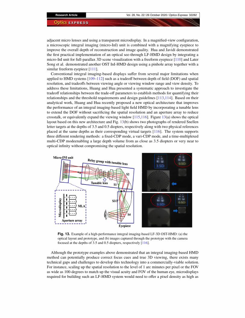
applied to HMD systems [109–112] such as a tradeoff between depth of field (DOF) and spatialresolution, and tradeoffs between viewing angle or viewing window range and view density. Toaddress these limitations, Huang and Hua presented a systematic approach to investigate thetradeoff relationships between the trade-off parameters to establish methods for quantifying theirrelationships and the threshold requirements and design guidelines [113,114]. Based on theiranalytical work, Huang and Hua recently proposed a new optical architecture that improvesthe performance of an integral imaging-based light field HMD by incorporating a tunable lensto extend the DOF without sacrificing the spatial resolution and an aperture array to reducecrosstalk, or equivalently expand the viewing window [115,116]. Figure 13(a) shows the opticallayout based on this new architecture and Fig. 13(b) shows two photographs of rendered Snellenletter targets at the depths of 3.5 and 0.5 diopters, respectively along with two physical referencesplaced at the same depths as their corresponding virtual targets [116]. The system supportsthree different rendering methods: a fixed-CDP mode, a vari-CDP mode, and a time-multiplexedmulti-CDP modeenabling a large depth volume from as close as 3.5 diopters or very near tooptical infinity without compromising the spatial resolution.
Fig. 13. Example of a high-performance integral imaging-based LF-3D OST-HMD: (a) theoptical layout and prototype, and (b) images captured through the prototype with the camerafocused at the depths of 3.5 and 0.5 diopters, respectively [116].
Although the prototype examples above demonstrated that an integral imaging-based HMDmethod can potentially produce correct focus cues and true 3D viewing, there exists manytechnical gaps and challenges to develop this technology into a commercially-viable solution.For instance, scaling up the spatial resolution to the level of 1 arc minutes per pixel or the FOVas wide as 100-degrees to match up the visual acuity and FOV of the human eye, microdisplaysrequired for building such an LF-HMD system would need to offer a pixel density as high as
Research Article Vol. 28, No. 22 / 26 October 2020 / Optics Express 32283
25000 pixels per inch (PPI), which is still beyond the reach of today’s display technology, notmentioning the amount of required computational power.
13. Innovation of 3D integral imaging display and AR for biomedicine
3D information can significantly accelerate human cognition compared with 2D information inmedical applications. High quality, high accuracy and real-time processing, visualization, displayof 3D image are important for accurate medical decision-making, which can reduce invasivenessand improve the precision in surgical treatment. Researchers have made significant progresses in3D medical integral imaging display and intelligent augmented reality (AR) surgical navigationsystem.The 3D medical display is first required to have high resolution and high accuracy during
the reproducing of images of anatomic structures. In the field of high-performance 3D medicalintegral imaging display, a multi-projector based high-quality display method was proposed tosolve the inadequate pixel density problem of the 2D elemental image [117]. To further breakthe trade-off between viewing angle and resolution of conventional integral imaging technique,an image enhancement method for the 3D AR system was proposed to achieve enhancedimage resolution and enlarged viewing angle at the same time [118]. With the development oftelemedicine and medical education, the 3D medical display is required to present a larger scenewith long viewing depth. A computer-generated integral imaging elemental image generationmethod was proposed to achieve a long visualization depth [119].
The second requirement of the 3Dmedical visualization is high-quality and real-time rendering.Super-multiview integral imaging can provide better image quality and interactivity, but alsosuffers from high-consuming problem during rendering. A real-time lens based renderingalgorithm for super-multiview integral imaging without image resampling was proposed andshowed a significant advantage in image quality and calculation efficiency [120]. The researchdemonstrated that real-time 3D medical display and interaction system could potentially help topromote medical learning efficiency and to reduce operational time for medical education andtraining [121].A novel AR navigation system using the real 3D image in situ overlay for intuitive guidance
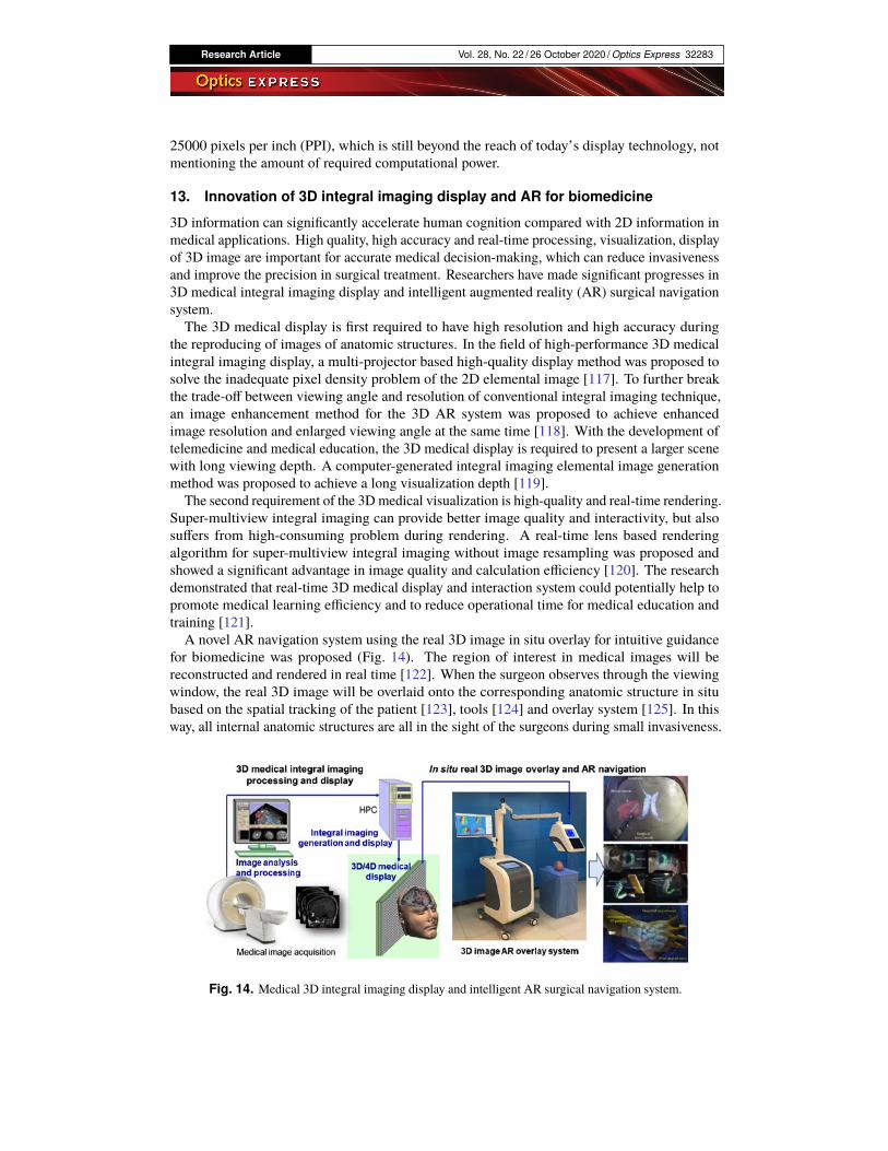
for biomedicine was proposed (Fig. 14). The region of interest in medical images will bereconstructed and rendered in real time [122]. When the surgeon observes through the viewingwindow, the real 3D image will be overlaid onto the corresponding anatomic structure in situbased on the spatial tracking of the patient [123], tools [124] and overlay system [125]. In thisway, all internal anatomic structures are all in the sight of the surgeons during small invasiveness.
Fig. 14. Medical 3D integral imaging display and intelligent AR surgical navigation system.
Research Article Vol. 28, No. 22 / 26 October 2020 / Optics Express 32284
The 3D AR overlay system has been used in clinical experiments in neurosurgery, orthopedicsurgery, maxillofacial surgery and other areas.
Fast technical progress in recent years accelerated the innovation in the 3D display. Researchersproposed an innovative MEMS-scanning-mechanism-based light homogeneous emitting au-tostereoscopic 3D display approach without the need for optical lenses or gratings and achieved asuper long viewing distance of over six meters [126]. The integration of conventional integralimaging and multilayer light field display will also open up new areas of future 3D medicaldisplay [127].
14. Tabletop integral imaging 3D display
Tabletop 3D display is one of the most challenging and interesting 3D displays [128,129]. Itenables vivid and natural 3D visual experience, and 360-degree viewing zone. Because of theunique full-parallax and full-color characteristics of integral imaging, it is a natural consequenceto apply integral imaging concept to the tabletop 3D display. The first proposal in this sensewas made by J. H. Park who used this technology with the aim of displaying 3D images with360-degree lateral viewing zone [130]. Later, some improved system configurations have beenproposed [131–135].
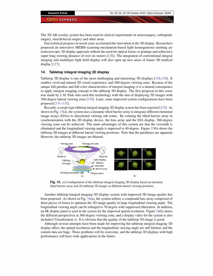
Recently, a swept-type tabletop integral imaging 3D display system has been reported [135]. Asshown in Fig. 15(a), the system uses a dynamic tilted barrier array to integrate different elementalimage arrays (EIAs) to directional viewing sub zones. By rotating the tilted barrier array insynchronization with the 2D display device, the lens array and the EIA display, 360-degreeviewing zone can be achieved. The main advantages of this system are that the crosstalk iseliminated and the longitudinal viewing angle is improved to 40-degree. Figure 15(b) shows thetabletop 3D images at different lateral viewing positions. Note that the parallaxes are apparent.However, the tabletop 3D images are blurred.
Fig. 15. (a) Configuration of the tabletop integral imaging 3D display based on dynamictilted barrier array and (b) tabletop 3D images at different lateral viewing positions.
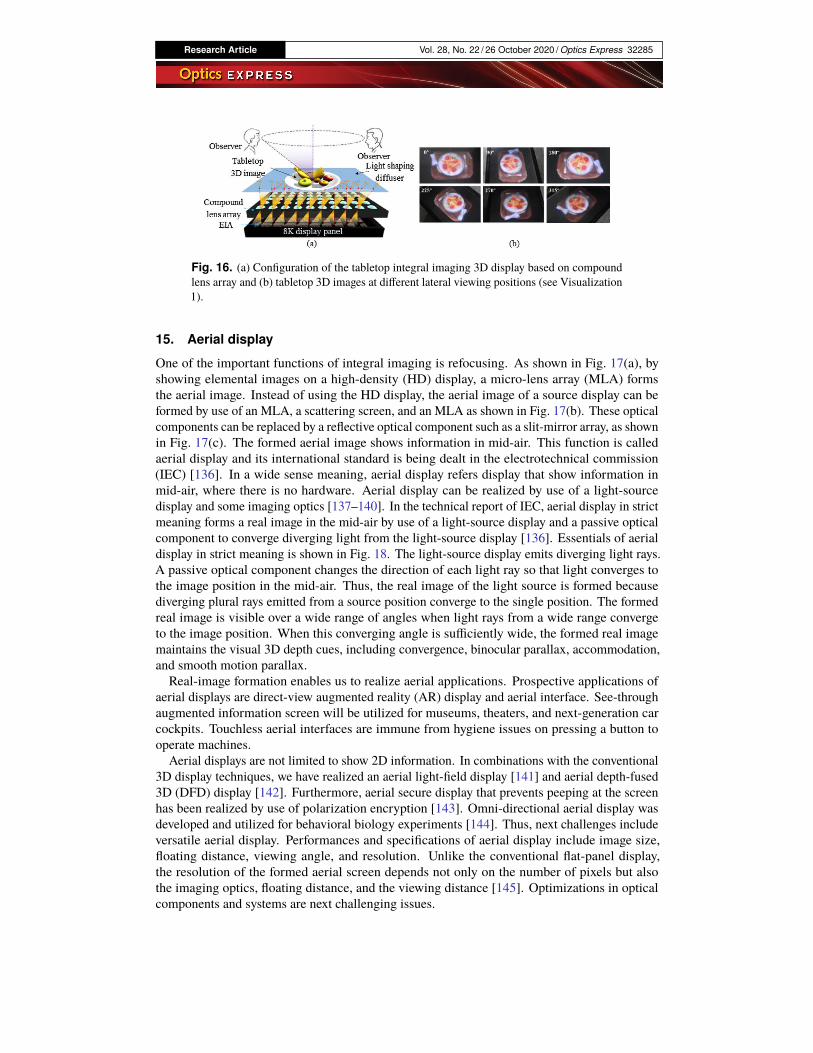
Another tabletop integral imaging 3D display system with improved 3D image quality hasbeen proposed. As shown in Fig. 16(a), the system utilizes a compound lens array comprised ofthree pieces of lenses to optimize the 3D image quality in large longitudinal viewing angle. Thelongitudinal viewing angle can be enlarged to 70-degree with suppressed aberration. In addition,an 8K display panel is used in the system for the improved spatial resolution. Figure 16(b) showsthe different perspectives at 360-degree viewing zone, and a display video for the system is alsoincluded (Visualization 1). It is obvious that the quality of the tabletop 3D image is good.Although several attempts have been made for improving the tabletop integral imaging 3D
display effect, the spatial resolution and the longitudinal viewing angle are still limited, and thecontent data are huge. These problems will be overcome, and the tabletop 3D displays with highperformance will have wide applications in the future.
Research Article Vol. 28, No. 22 / 26 October 2020 / Optics Express 32285
Fig. 16. (a) Configuration of the tabletop integral imaging 3D display based on compoundlens array and (b) tabletop 3D images at different lateral viewing positions (see Visualization1).
15. Aerial display
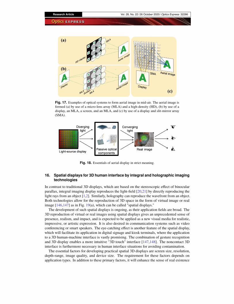
One of the important functions of integral imaging is refocusing. As shown in Fig. 17(a), byshowing elemental images on a high-density (HD) display, a micro-lens array (MLA) formsthe aerial image. Instead of using the HD display, the aerial image of a source display can beformed by use of an MLA, a scattering screen, and an MLA as shown in Fig. 17(b). These opticalcomponents can be replaced by a reflective optical component such as a slit-mirror array, as shownin Fig. 17(c). The formed aerial image shows information in mid-air. This function is calledaerial display and its international standard is being dealt in the electrotechnical commission(IEC) [136]. In a wide sense meaning, aerial display refers display that show information inmid-air, where there is no hardware. Aerial display can be realized by use of a light-sourcedisplay and some imaging optics [137–140]. In the technical report of IEC, aerial display in strictmeaning forms a real image in the mid-air by use of a light-source display and a passive opticalcomponent to converge diverging light from the light-source display [136]. Essentials of aerialdisplay in strict meaning is shown in Fig. 18. The light-source display emits diverging light rays.A passive optical component changes the direction of each light ray so that light converges tothe image position in the mid-air. Thus, the real image of the light source is formed becausediverging plural rays emitted from a source position converge to the single position. The formedreal image is visible over a wide range of angles when light rays from a wide range convergeto the image position. When this converging angle is sufficiently wide, the formed real imagemaintains the visual 3D depth cues, including convergence, binocular parallax, accommodation,and smooth motion parallax.Real-image formation enables us to realize aerial applications. Prospective applications of
aerial displays are direct-view augmented reality (AR) display and aerial interface. See-throughaugmented information screen will be utilized for museums, theaters, and next-generation carcockpits. Touchless aerial interfaces are immune from hygiene issues on pressing a button tooperate machines.
Aerial displays are not limited to show 2D information. In combinations with the conventional3D display techniques, we have realized an aerial light-field display [141] and aerial depth-fused3D (DFD) display [142]. Furthermore, aerial secure display that prevents peeping at the screenhas been realized by use of polarization encryption [143]. Omni-directional aerial display wasdeveloped and utilized for behavioral biology experiments [144]. Thus, next challenges includeversatile aerial display. Performances and specifications of aerial display include image size,floating distance, viewing angle, and resolution. Unlike the conventional flat-panel display,the resolution of the formed aerial screen depends not only on the number of pixels but alsothe imaging optics, floating distance, and the viewing distance [145]. Optimizations in opticalcomponents and systems are next challenging issues.
Research Article Vol. 28, No. 22 / 26 October 2020 / Optics Express 32286
Fig. 17. Examples of optical systems to form aerial image in mid-air. The aerial image isformed (a) by use of a micro-lens array (MLA) and a high-density (HD), (b) by use of adisplay, an MLA, a screen, and an MLA, and (c) by use of a display and slit-mirror array(SMA).
Fig. 18. Essentials of aerial display in strict meaning.
16. Spatial displays for 3D human interface by integral and holographic imagingtechnologies
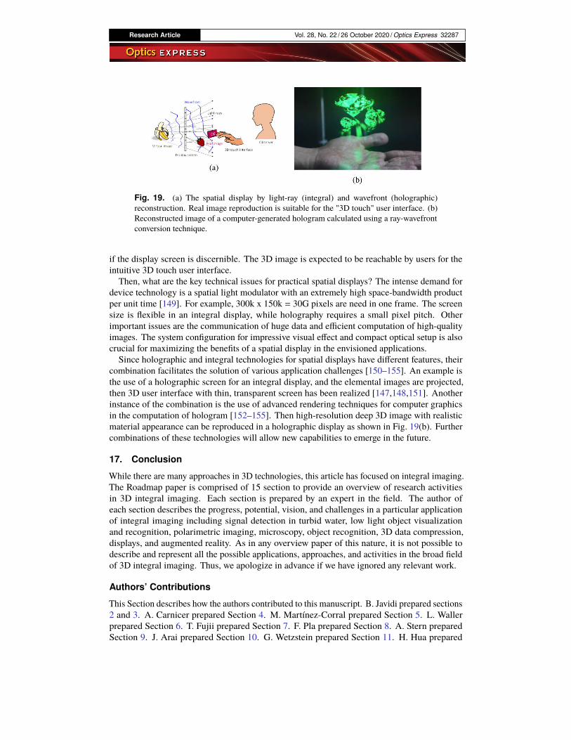
In contrast to traditional 3D displays, which are based on the stereoscopic effect of binocularparallax, integral imaging display reproduces the light-field [20,21] by directly reproducing thelight rays from an object [1,2]. Similarly, holography can reproduce the wavefront from an object.Both technologies allow for the reproduction of 3D space in the form of virtual image or realimage [146,147] as in Fig. 19(a), which can be called "spatial displays."
The development of such spatial displays is ongoing, as their application fields are broad. The3D reproduction of virtual or real images using spatial displays gives an unprecedented sense ofpresence, realism, and impact, and is expected to be applied as a new visual media for realistic,impressive, or artistic expression. It is also desired in communication systems such as videoconferencing or smart speakers. The eye-catching effect is another feature of the spatial display,which will facilitate its application in digital signage and kiosk terminals, where the applicationto a 3D human-machine interface is vastly promising. The combination of gesture recognitionand 3D display enables a more intuitive "3D touch" interface [147,148]. The noncontact 3Dinterface is furthermore necessary in human interface situations for avoiding contamination.The essential factors for developing practical spatial 3D displays are screen size, resolution,
depth-range, image quality, and device size. The requirement for these factors depends onapplication types. In addition to these primary factors, it will enhance the sense of real existence
Research Article Vol. 28, No. 22 / 26 October 2020 / Optics Express 32287
Fig. 19. (a) The spatial display by light-ray (integral) and wavefront (holographic)reconstruction. Real image reproduction is suitable for the "3D touch" user interface. (b)Reconstructed image of a computer-generated hologram calculated using a ray-wavefrontconversion technique.
if the display screen is discernible. The 3D image is expected to be reachable by users for theintuitive 3D touch user interface.
Then, what are the key technical issues for practical spatial displays? The intense demand fordevice technology is a spatial light modulator with an extremely high space-bandwidth productper unit time [149]. For example, 300k x 150k = 30G pixels are need in one frame. The screensize is flexible in an integral display, while holography requires a small pixel pitch. Otherimportant issues are the communication of huge data and efficient computation of high-qualityimages. The system configuration for impressive visual effect and compact optical setup is alsocrucial for maximizing the benefits of a spatial display in the envisioned applications.Since holographic and integral technologies for spatial displays have different features, their
combination facilitates the solution of various application challenges [150–155]. An example isthe use of a holographic screen for an integral display, and the elemental images are projected,then 3D user interface with thin, transparent screen has been realized [147,148,151]. Anotherinstance of the combination is the use of advanced rendering techniques for computer graphicsin the computation of hologram [152–155]. Then high-resolution deep 3D image with realisticmaterial appearance can be reproduced in a holographic display as shown in Fig. 19(b). Furthercombinations of these technologies will allow new capabilities to emerge in the future.
17. Conclusion
While there are many approaches in 3D technologies, this article has focused on integral imaging.The Roadmap paper is comprised of 15 section to provide an overview of research activitiesin 3D integral imaging. Each section is prepared by an expert in the field. The author ofeach section describes the progress, potential, vision, and challenges in a particular applicationof integral imaging including signal detection in turbid water, low light object visualizationand recognition, polarimetric imaging, microscopy, object recognition, 3D data compression,displays, and augmented reality. As in any overview paper of this nature, it is not possible todescribe and represent all the possible applications, approaches, and activities in the broad fieldof 3D integral imaging. Thus, we apologize in advance if we have ignored any relevant work.
Authors’ Contributions
This Section describes how the authors contributed to this manuscript. B. Javidi prepared sections2 and 3. A. Carnicer prepared Section 4. M. Martínez-Corral prepared Section 5. L. Wallerprepared Section 6. T. Fujii prepared Section 7. F. Pla prepared Section 8. A. Stern preparedSection 9. J. Arai prepared Section 10. G. Wetzstein prepared Section 11. H. Hua prepared

Research Article Vol. 28, No. 22 / 26 October 2020 / Optics Express 32288
Section 12. H. Liao prepared Section 13. Q.-H. Wang prepared Section 14. H. Yamamotoprepared Section 15. M. Yamaguchi prepared Section 16.
B. Javidi and A. Carnicer coordinated the organization of the paper and prepared the Abstract,Introduction, and Conclusion. All authors reviewed the manuscript.
Funding
Air ForceOffice of ScientificResearch (FA9550-18-1-0338); Office ofNavalResearch (N000141712405,N00014-17-1-2561, N00014-20-1-2690); Ministerio de Economía, Industria y Competitividad,Gobierno de España (FIS2016-75147-C3-1-P); Agencia Estatal de Investigación (PID2019-104268GB-C22); Ministerio de Ciencia, Innovación y Universidades (RTI2018-099041-B-I00);Generalitat Valenciana (PROMETEOII/2014/062); Universitat Jaume I (P11B2014-09); JapanSociety for the Promotion of Science (15K04691, 18H03256); National Natural Science Foun-dation of China (81771940); National Key Research and Development Program of China(2017YFC0108000).
Acknowledgments
Jun Arai sincerely acknowledge fruitful discussions with Dr. Masahiro Kawakita.
Disclosures
Hong Hua has a disclosed financial interest in Magic Leap Inc. The terms of this arrangementhave been properly disclosed to The University of Arizona and reviewed by the InstitutionalReview Committee in accordance with its conflict of interest policies.Manuel Martínez-Corral: DoitPlenoptic S.L. (Personal Financial Interest, Patent, Non-
Renumerative).The rest of the authors declare no conflicts of interest.
References1. G. Lippmann, “Epreuves reversibles donnant la sensation du relief,” J. Phys. 7(1), 821–825 (1908).2. A. Sokolov, Autostereoscopy and integral photography by Professor Lippmann’s method (Moscow State University,
1911).3. H. E. Ives, “Optical properties of a Lippmann lenticulated sheet,” J. Opt. Soc. Am. 21(3), 171–176 (1931).4. C. Burckhardt, “Optimum parameters and resolution limitation of integral photography,” J. Opt. Soc. Am. 58(1),
71–76 (1968).5. Y. Igarashi, H. Murata, and M. Ueda, “3-D display system using a computer generated integral photograph,” Jpn. J.
Appl. Phys. 17(9), 1683–1684 (1978).6. N. Davies, M. McCormick, and L. Yang, “Three-dimensional imaging systems: a new development,” Appl. Opt.
27(21), 4520–4528 (1988).7. F. Okano, H. Hoshino, J. Arai, and I. Yuyama, “Real-time pickup method for a three-dimensional image based on
integral photography,” Appl. Opt. 36(7), 1598–1603 (1997).8. J. Arai, F. Okano, H. Hoshino, and I. Yuyama, “Gradient-index lens-array method based on real-time integral
photography for three-dimensional images,” Appl. Opt. 37(11), 2034–2045 (1998).9. S. Manolache, A. Aggoun, M. McCormick, N. Davies, and S.-Y. Kung, “Analytical model of a three-dimensional
integral image recording system that uses circular-and hexagonal-based spherical surface microlenses,” J. Opt. Soc.Am. A 18(8), 1814–1821 (2001).
10. H. Arimoto and B. Javidi, “Integral three-dimensional imaging with digital reconstruction,” Opt. Lett. 26(3), 157–159(2001).
11. J.-S. Jang and B. Javidi, “Three-dimensional synthetic aperture integral imaging,” Opt. Lett. 27(13), 1144–1146(2002).
12. J.-S. Jang and B. Javidi, “Improved viewing resolution of three-dimensional integral imaging by use of nonstationarymicro-optics,” Opt. Lett. 27(5), 324–326 (2002).
13. J.-S. Jang and B. Javidi, “Three-dimensional integral imaging with electronically synthesized lenslet arrays,” Opt.Lett. 27(20), 1767–1769 (2002).
14. H. Hiura, K. Komine, J. Arai, and T. Mishina, “Measurement of static convergence and accommodation responses toimages of integral photography and binocular stereoscopy,” Opt. Express 25(4), 3454–3468 (2017).
15. J. Geng, “Three-dimensional display technologies,” Adv. Opt. Photonics 5(4), 456–535 (2013).

Research Article Vol. 28, No. 22 / 26 October 2020 / Optics Express 32289
16. M. Martínez-Corral and B. Javidi, “Fundamentals of 3D imaging and displays: a tutorial on integral imaging,light-field, and plenoptic systems,” Adv. Opt. Photonics 10(3), 512–566 (2018).
17. A. Stern and B. Javidi, “Three-dimensional image sensing, visualization, and processing using integral imaging,”Proc. IEEE 94(3), 591–607 (2006).
18. S. Yeom, B. Javidi, and E. Watson, “Photon counting passive 3d image sensing for automatic target recognition,” Opt.Express 13(23), 9310–9330 (2005).
19. E. H. Adelson and J. R. Bergen, “The plenoptic function and the elements of early vision,” in Computational Modelsof Visual Processing, L. M. and J. Movshon, eds. (MIT, Camdridge. MA, 1991), pp. 3–20.
20. E. H. Adelson and J. Y. A. Wang, “Single lens stereo with a plenoptic camera,” IEEE Trans. Pattern Anal. MachineIntell. 14(2), 99–106 (1992).
21. A. Isaksen, L. McMillan, and S. J. Gortler, “Dynamically reparameterized light fields,” in Proceedings of SIGGRAPH00, Annual Conference Series, (ACM, 2000), pp. 297–306.
22. B. Wilburn, N. Joshi, V. Vaish, E.-V. Talvala, E. Antunez, A. Barth, A. Adams, M. Horowitz, and M. Levoy, “Highperformance imaging using large camera arrays,” ACM Trans. Graph. 24(3), 765–776 (2005).
23. R. Ng, M. Levoy, M. Brédif, G. Duval, M. Horowitz, and P. Hanrahan, “Light field photography with a hand-heldplenoptic camera,” Tech. rep., Standford University (2005).
24. M. Tanimoto, M. P. Tehrani, T. Fujii, and T. Yendo, “Free-viewpoint tv,” IEEE Signal Process. Mag. 28(1), 67–76(2011).
25. J.-S. Jang and B. Javidi, “Three-dimensional integral imaging of micro-objects,” Opt. Lett. 29(11), 1230–1232(2004).
26. M. Levoy, R. Ng, A. Adams, M. Footer, and M. Horowitz, “Light field microscopy,” ACM Trans. Graph 25(3),924–934 (2006).
27. B. Javidi, I. Moon, and S. Yeom, “Three-dimensional identification of biological microorganism using integralimaging,” Opt. Express 14(25), 12096–12108 (2006).
28. A. Llavador, J. Sola-Pikabea, G. Saavedra, B. Javidi, and M. Martínez-Corral, “Resolution improvements in integralmicroscopy with fourier plane recording,” Opt. Express 24(18), 20792–20798 (2016).
29. M. Martínez-Corral, A. Dorado, J. C. Barreiro, G. Saavedra, and B. Javidi, “Recent advances in the capture anddisplay of macroscopic and microscopic 3-D scenes by integral imaging,” Proc. IEEE 105(5), 825–836 (2017).
30. S. Komatsu, A. Markman, and B. Javidi, “Optical sensing and detection in turbid water using multidimensionalintegral imaging,” Opt. Lett. 43(14), 3261–3264 (2018).
31. R. Joshi, T. O’Connor, X. Shen, M. Wardlaw, and B. Javidi, “Optical 4D signal detection in turbid water bymulti-dimensional integral imaging using spatially distributed and temporally encoded multiple light sources,” Opt.Express 28(7), 10477–10490 (2020).
32. R. Joshi, T. O’Connor, X. Shen, M. Wardlaw, and B. Javidi, “Overview of optical 4D signal detection in turbid waterby multi-dimensional integral imaging using spatially distributed and temporally encoded multiple light sources,”Proc. SPIE 11402, 114020F (2020).
33. M. Cho and B. Javidi, “Peplography – a passive 3D photon counting imaging through scattering media,” Opt. Lett.41(22), 5401–5404 (2016).
34. I. Moon and B. Javidi, “Three-dimensional visualization of objects in scattering medium by use of computationalintegral imaging,” Opt. Express 16(17), 13080–13089 (2008).
35. S.-H. Hong, J.-S. Jang, and B. Javidi, “Three-dimensional volumetric object reconstruction using computationalintegral imaging,” Opt. Express 12(3), 483–491 (2004).
36. M. B. Mollah and M. R. Islam, “Comparative analysis of gold codes with PN codes using correlation property inCDMA technology,” in Proceedings of 2012 International Conference on Computer Communication and Informatics,(IEEE, 2012), pp. 1–6.
37. B. Javidi, X. Shen, A. S. Markman, P. Latorre-Carmona, A. Martinez-Uso, J. M. Sotoca, F. Pla, M. Martinez-Corral,G. Saavedra, Y.-P. Huang, and A. Stern, “Multidimensional optical sensing and imaging system (MOSIS): frommacroscales to microscales,” Proc. IEEE 105(5), 850–875 (2017).
38. A. Markman, X. Shen, and B. Javidi, “Three-dimensional object visualization and detection in low light illuminationusing integral imaging,” Opt. Lett. 42(16), 3068–3071 (2017).
39. A. Markman and B. Javidi, “Learning in the dark: 3D integral imaging object recognition in very low illuminationconditions using convolutional neural networks,” OSA Continuum 1(2), 373–383 (2018).
40. M. DaneshPanah, B. Javidi, and E. A. Watson, “Three dimensional object recognition with photon counting imageryin the presence of noise,” Opt. Express 18(25), 26450–26460 (2010).
41. B. Tavakoli, B. Javidi, and E. Watson, “Three dimensional visualization by photon counting computational integralimaging,” Opt. Express 16(7), 4426–4436 (2008).
42. A. Stern, D. Aloni, and B. Javidi, “Experiments with three-dimensional integral imaging under low light levels,”IEEE Photonics J. 4(4), 1188–1195 (2012).
43. D. Aloni, A. Stern, and B. Javidi, “Three-dimensional photon counting integral imaging reconstruction usingpenalized maximum likelihood expectation maximization,” Opt. Express 19(20), 19681–19687 (2011).
44. A. Markman, T. O’Connor, H. Hotaka, S. Ohsuka, and B. Javidi, “Three-dimensional integral imaging in photon-starved environments with high-sensitivity image sensors,” Opt. Express 27(19), 26355–26368 (2019).

Research Article Vol. 28, No. 22 / 26 October 2020 / Optics Express 32290
45. H. Hotaka, T. O’Connor, S. Ohsuka, and B. Javidi, “Photon-counting 3D integral imaging with less than a singlephoton per pixel on average using a statistical model of the EM-CCD camera,” Opt. Lett. 45(8), 2327–2330 (2020).
46. S. H. Chan, R. Khoshabeh, K. B. Gibson, P. E. Gill, and T. Q. Nguyen, “An augmented lagrangian method for totalvariation video restoration,” IEEE Trans. on Image Process. 20(11), 3097–3111 (2011).
47. P. Viola, M. J. Jones, and D. Snow, “Detecting pedestrians using patterns of motion and appearance,” Int. J. Comput.Vis. 63(2), 153–161 (2005).
48. L. B. Wolff, “Polarization vision: a new sensory approach to image understanding,” Image Vision Comput. 15(2),81–93 (1997).
49. O. Matoba and B. Javidi, “Three-dimensional polarimetric integral imaging,” Opt. Lett. 29(20), 2375–2377 (2004).50. X. Xiao, B. Javidi, G. Saavedra, M. Eismann, andM.Martinez-Corral, “Three-dimensional polarimetric computational
integral imaging,” Opt. Express 20(14), 15481–15488 (2012).51. X. Xiao, B. Javidi, M. Martinez-Corral, and A. Stern, “Advances in three-dimensional integral imaging: sensing,
display, and applications,” Appl. Opt. 52(4), 546–560 (2013).52. A. Carnicer and B. Javidi, “Polarimetric 3D integral imaging in photon-starved conditions,” Opt. Express 23(5),
6408–6417 (2015).53. X. Shen, A. Carnicer, and B. Javidi, “Three-dimensional polarimetric integral imaging under low illumination
conditions,” Opt. Lett. 44(13), 3230–3233 (2019).54. A. Carnicer, S. Bosch, and B. Javidi, “Mueller matrix polarimetry with 3D integral imaging,” Opt. Express 27(8),
11525–11536 (2019).55. C. D. F. Winnek, “Apparatus for making a composite stereograph,” (1936). US Patent 2,063,985.56. M. Levoy, Z. Zhang, and I. McDowall, “Recording and controlling the 4d light field in a microscope using microlens
arrays,” J. Microsc. 235(2), 144–162 (2009).57. A. Lumsdaine and T. Georgiev, “The focused plenoptic camera,” in 2009 IEEE International Conference on
Computational Photography (ICCP), (IEEE, 2009), pp. 1–8.58. K.-C. Kwon, M.-U. Erdenebat, M. A. Alam, Y.-T. Lim, K. G. Kim, and N. Kim, “Integral imaging microscopy with
enhanced depth-of-field using a spatial multiplexing,” Opt. Express 24(3), 2072–2083 (2016).59. G. Scrofani, J. Sola-Pikabea, A. Llavador, E. Sanchez-Ortiga, J. Barreiro, G. Saavedra, J. Garcia-Sucerquia, and M.
Martínez-Corral, “FIMic: design for ultimate 3D-integral microscopy of in-vivo biological samples,” Biomed. Opt.Express 9(1), 335–346 (2018).
60. L. Cong, Z. Wang, Y. Chai, W. Hang, C. Shang, W. Yang, L. Bai, J. Du, K. Wang, and Q. Wen, “Rapid whole brainimaging of neural activity in freely behaving larval zebrafish (danio rerio),” eLife 6, e28158 (2017).
61. N.Wagner, N. Norlin, J. Gierten, G. deMedeiros, B. Balázs, J. Wittbrodt, L. Hufnagel, and R. Prevedel, “Instantaneousisotropic volumetric imaging of fast biological processes,” Nat. Methods 16(6), 497–500 (2019).
62. Y. Da Sie, C.-Y. Lin, and S.-J. Chen, “3D surface morphology imaging of opaque microstructures via light-fieldmicroscopy,” Sci. Rep. 8(1), 10505 (2018).
63. N. Antipa, S. Necula, R. Ng, and L. Waller, “Single-shot diffuser-encoded light field imaging,” in 2016 IEEEInternational Conference on Computational Photography (ICCP), (IEEE, 2016), pp. 1–11.
64. M. Broxton, L. Grosenick, S. Yang, N. Cohen, A. Andalman, K. Deisseroth, and M. Levoy, “Wave optics theory and3-D deconvolution for the light field microscope,” Opt. Express 21(21), 25418–25439 (2013).
65. K. Yanny, N. Antipa, R. Ng, and L. Waller, “Miniature 3D fluorescence microscope using random microlenses,” inOptics and the Brain, (Optical Society of America, 2019), pp. BT3A–4.
66. F. L. Liu, V. Madhavan, N. Antipa, G. Kuo, S. Kato, and L. Waller, “Single-shot 3D fluorescence microscopy withfourier diffusercam,” in Novel Techniques in Microscopy, (Optical Society of America, 2019), pp. NS2B–3.
67. N. Antipa, G. Kuo, R. Heckel, B. Mildenhall, E. Bostan, R. Ng, and L. Waller, “Diffusercam: lensless single-exposure3D imaging,” Optica 5(1), 1–9 (2018).
68. G. Kuo, F. L. Liu, I. Grossrubatscher, R. Ng, and L. Waller, “On-chip fluorescence microscopy with a randommicrolens diffuser,” Opt. Express 28(6), 8384–8399 (2020).
69. N. Antipa, P. Oare, E. Bostan, R. Ng, and L. Waller, “Video from stills: Lensless imaging with rolling shutter,” in2019 IEEE International Conference on Computational Photography (ICCP), (IEEE, 2019), pp. 1–8.
70. M. Levoy and P. Hanrahan, “Light field rendering, in Proceedings of SIGGRAPH 96,” Annual Conference Series,(1996), pp. 31–42.
71. T. Fujii, “Ray space coding for 3d visual communication,” in Picture Coding Symposium’96, vol. 2 (1996), pp.447–451.
72. M. Magnor and B. Girod, “Data compression for light-field rendering,” IEEE Trans. Circuits Syst. Video Technol.10(3), 338–343 (2000).
73. M. Rerabek, T. Bruylants, T. Ebrahimi, F. Pereira, and P. Schelkens, “Icme 2016 grand challenge: Light-field imagecompression,” Tech. rep., Seattle, USA (2016).
74. T. Ebrahimi, S. Foessel, F. Pereira, and P. Schelkens, “JPEG pleno: Toward an efficient representation of visualreality,” IEEE Multimedia 23(4), 14–20 (2016).
75. C. Perra, P. Astola, E. A. da Silva, H. Khanmohammad, C. Pagliari, P. Schelkens, and I. Tabus, “Performance analysisof JPEG pleno light field coding,” Proc. SPIE 11137, 111371H (2019).
76. International Organization for Standardization, “Plenoptic image coding system (JPEG pleno) part 2: Light fieldcoding,” Standard ISO/IEC DIS 21794-2, International Organization for Standardization, Geneva, CH (2020).

Research Article Vol. 28, No. 22 / 26 October 2020 / Optics Express 32291
77. International Organization for Standardization, “Summary on MPEG-I visual activities,” Standard ISO/IECJTC1/SC29/WG11 MPEG2019/N19218, International Organization for Standardization, Geneva, CH (2020).
78. C. Perra, “International Organization for Standardization, Activity report on dense light fields,” Standard ISO/IECJTC1/SC29/WG11 MPEG2020/N19222, International Organization for Standardization, Geneva, CH (2020).
79. C. Jia, X. Zhang, S. Wang, S. Wang, and S. Ma, “Light field image compression using generative adversarialnetwork-based view synthesis,” IEEE Trans. Emerg. Sel. Topics Circuits Syst. 9(1), 177–189 (2019).
80. L. Chen, H. Wei, and J. Ferryman, “A survey of human motion analysis using depth imagery,” Pattern Recognit. Lett.34(15), 1995–2006 (2013).
81. H. Cheng, L. Yang, and Z. Liu, “Survey on 3d hand gesture recognition,” IEEE Trans. Circuits Syst. Video Technol.26(9), 1659–1673 (2016).
82. L. L. Presti and M. La Cascia, “3d skeleton-based human action classification: A survey,” Pattern Recognit. 53,130–147 (2016).
83. V. J. Traver, P. Latorre-Carmona, E. Salvador-Balaguer, F. Pla, and B. Javidi, “Human gesture recognition usingthree-dimensional integral imaging,” J. Opt. Soc. Am. A 31(10), 2312–2320 (2014).
84. V. J. Traver, P. Latorre-Carmona, E. Salvador-Balaguer, F. Pla, and B. Javidi, “Three-dimensional integral imagingfor gesture recognition under occlusions,” IEEE Signal Process. Lett. 24(2), 171–175 (2017).
85. A. Stern, Y. Yitzhaky, and B. Javidi, “Perceivable light fields: Matching the requirements between the human visualsystem and autostereoscopic 3-D displays,” Proc. IEEE 102(10), 1571–1587 (2014).
86. A. Stern and B. Javidi, “Using perceivable light fields to evaluate the amount of information that autostereoscopicdisplays need to cast,” Proc. SPIE 9495, 94950J (2015).
87. A. Stern and B. Javidi, “Ray phase space approach for 3-D imaging and 3-D optical data representation,” J. Disp.Technol. 1(1), 141–150 (2005).
88. C.-K. Liang, Y.-C. Shih, and H. H. Chen, “Light field analysis for modeling image formation,” IEEE Trans. on ImageProcess. 20(2), 446–460 (2011).
89. F. Jin, J.-S. Jang, and B. Javidi, “Effects of device resolution on three-dimensional integral imaging,” Opt. Lett.29(12), 1345–1347 (2004).
90. M. McCormick, “Integral 3D image for broadcast,” in Proc. 2nd International Display Workshop, 1995, (1995).91. H. Watanabe, N. Okaichi, T. Omura, M. Kano, H. Sasaki, and M. Kawakita, “Aktina vision: Full-parallax
three-dimensional display with 100 million light rays,” Sci. Rep. 9(1), 17688 (2019).92. H. Omura, T. Watanabe, N. Okaichi, M. Sasaki, and H. Kawakita, “Full-parallax 3D display using time-multiplexing
projection technology,” in Proc. IS&T International Symposium on Electronic Imaging, (IS&T, 2020), pp. SD&A–100.93. Z.-L. Xiong, Q.-H. Wang, S.-L. Li, H. Deng, and C.-C. Ji, “Partially-overlapped viewing zone based integral imaging
system with super wide viewing angle,” Opt. Express 22(19), 22268–22277 (2014).94. N. Okaichi, H. Sasaki, H. Watanabe, K. Hisatomi, and M. Kawakita, “Integral 3D display with eye-tracking system
using 8k display,” in Proc. ITE Winter Annual Convention, (ITE, 2018), pp. 23D–3.95. “NHK (Japan Broadcasting Corporation) Science & Technology Research Laboratories Annual Report,” Tech. rep.
(2018).96. G. Wetzstein, D. Lanman, M. Hirsch, and R. Raskar, “Tensor displays: compressive light field synthesis using
multilayer displays with directional backlighting,” ACM Trans. Graph. 34(4), 1–11 (2012).97. K. Marwah, G. Wetzstein, Y. Bando, and R. Raskar, “Compressive light field photography using overcomplete
dictionaries and optimized projections,” ACM Trans. Graph. 32(4), 1–12 (2013).98. F.-C. Huang, K. Chen, and G. Wetzstein, “The light field stereoscope: Immersive computer graphics via factored
near-eye light field display with focus cues,” (Association for Computing Machinery, 2015), p. 60.99. S. Liu, D. Cheng, and H. Hua, “An optical see-through head mounted display with addressable focal planes,” in 2008
7th IEEE/ACM International Symposium on Mixed and Augmented Reality, (IEEE, 2008), pp. 33–42.100. N. Padmanaban, R. Konrad, T. Stramer, E. A. Cooper, and G. Wetzstein, “Optimizing virtual reality for all users
through gaze-contingent and adaptive focus displays,” Proc. Natl. Acad. Sci. U. S. A. 114(9), 2183–2188 (2017).101. K. Akeley, S. J. Watt, A. R. Girshick, and M. S. Banks, “A stereo display prototype with multiple focal distances,”
ACM Trans. Graph. 23(3), 804–813 (2004).102. R. Anderson, D. Gallup, J. T. Barron, J. Kontkanen, N. Snavely, C. Hernández, S. Agarwal, and S. M. Seitz, “Jump:
virtual reality video,” ACM Trans. Graph. 35(6), 1–13 (2016).103. R. Konrad, D. G. Dansereau, A. Masood, and G. Wetzstein, “Spinvr: towards live-streaming 3D virtual reality
video,” ACM Trans. Graph. 36(6), 1–12 (2017).104. A. Tewari, O. Fried, J. Thies, V. Sitzmann, S. Lombardi, K. Sunkavalli, R. Martin-Brualla, T. Simon, J. Saragih, M.
Niessner, R. Pandey, S. Fanello, G. Wetzstein, J.-Y. Zhu, C. Theobalt, M. Agrawala, E. Shechtman, D. B. Goldman,and M. Zollhöfer, “State of the art on neural rendering,” arXiv:2004.03805 (2020).
105. V. Sitzmann, M. Zollhöfer, and G. Wetzstein, “Scene representation networks: Continuous 3D-structure-awareneural scene representations,” in Advances in Neural Information Processing Systems, (2019), pp. 1119–1130.
106. A. Jones, I. McDowall, H. Yamada, M. Bolas, and P. Debevec, “Rendering for an interactive 360 light field display,”ACM Trans. Graph. 26(3), 40 (2007).
107. G. Wetzstein, D. Lanman, M. Hirsch, and R. Raskar, “Tensor displays: compressive light field synthesis usingmultilayer displays with directional backlighting,” ACM Trans. Graph. 31(4), 1–11 (2012).

Research Article Vol. 28, No. 22 / 26 October 2020 / Optics Express 32292
108. A. Maimone and H. Fuchs, “Computational augmented reality eyeglasses,” in 2013 IEEE International Symposiumon Mixed and Augmented Reality (ISMAR), (IEEE, 2013), pp. 29–38.
109. D. Lanman and D. Luebke, “Near-eye light field displays,” ACM Trans. Graph. 32(6), 1–10 (2013).110. H. Hua and B. Javidi, “A 3D integral imaging optical see-through head-mounted display,” Opt. Express 22(11),
13484–13491 (2014).111. W. Song, Y. Wang, D. Cheng, and Y. Liu, “Light field head-mounted display with correct focus cue using micro
structure array,” Chin. Opt. Lett. 12(6), 60010–60013 (2014).112. C. Yao, D. Cheng, and Y. Wang, “Design and stray light analysis of a lenslet-array-based see-through light-field
near-eye display,” Proc. SPIE 10676, 106761A (2018).113. H. Huang and H. Hua, “Systematic characterization and optimization of 3D light field displays,” Opt. Express
25(16), 18508–18525 (2017).114. H. Huang and H. Hua, “Effects of ray position sampling on the visual responses of 3D light field displays,” Opt.
Express 27(7), 9343–9360 (2019).115. H. Huang and H. Hua, “An integral-imaging-based head-mounted light field display using a tunable lens and
aperture array,” J. Soc. Inf. Display 25(3), 200–207 (2017).116. H. Huang and H. Hua, “High-performance integral-imaging-based light field augmented reality display using
freeform optics,” Opt. Express 26(13), 17578–17590 (2018).117. H. Liao, M. Iwahara, N. Hata, and T. Dohi, “High-quality integral videography using a multiprojector,” Opt. Express
12(6), 1067–1076 (2004).118. X. Zhang, G. Chen, and H. Liao, “High-quality see-through surgical guidance system using enhanced 3-D
autostereoscopic augmented reality,” IEEE Trans. Biomed. Eng. 64(8), 1815–1825 (2017).119. H. Liao, T. Dohi, and K. Nomura, “Autostereoscopic 3D display with long visualization depth using referential
viewing area-based integral photography,” IEEE Trans. Vis. Comput. Graph. 17(11), 1690–1701 (2011).120. G. Chen, C. Ma, Z. Fan, X. Cui, and H. Liao, “Real-time lens based rendering algorithm for super-multiview integral
photography without image resampling,” IEEE Trans. Vis. Comput. Graph. 24(9), 2600–2609 (2018).121. G. Chen, T. Huang, Z. Fan, X. Zhang, and H. Liao, “A naked eye 3D display and interaction system for medical
education and training,” J. Biomed. Inf. 100, 103319 (2019).122. H. Liao, T. Inomata, I. Sakuma, and T. Dohi, “3-D augmented reality for MRI-guided surgery using integral
videography autostereoscopic image overlay,” IEEE Trans. Biomed. Eng. 57(6), 1476–1486 (2010).123. J. Wang, H. Suenaga, K. Hoshi, L. Yang, E. Kobayashi, I. Sakuma, and H. Liao, “Augmented reality navigation
with automatic marker-free image registration using 3-D image overlay for dental surgery,” IEEE Trans. Biomed.Eng. 61(4), 1295–1304 (2014).
124. Z. Fan, G. Chen, J. Wang, and H. Liao, “Spatial position measurement system for surgical navigation using 3-Dimage marker-based tracking tools with compact volume,” IEEE Trans. Biomed. Eng. 65(2), 378–389 (2018).
125. C. Ma, G. Chen, X. Zhang, G. Ning, and H. Liao, “Moving-tolerant augmented reality surgical navigation systemusing autostereoscopic three-dimensional image overlay,” IEEE J. Biomed. Health Inform. 23(6), 2483–2493 (2019).
126. H. Liao, “Super long viewing distance light homogeneous emitting three-dimensional display,” Sci. Rep. 5(1), 9532(2015).
127. J. Zhang, Z. Fan, D. Sun, and H. Liao, “Unified mathematical model for multilayer-multiframe compressive lightfield displays using LCDs,” IEEE Trans. Vis. Comput. Graph. 25(3), 1603–1614 (2019).
128. S. Yoshida, “fVisiOn: 360-degree viewable glasses-free tabletop 3d display composed of conical screen and modularprojector arrays,” Opt. Express 24(12), 13194–13203 (2016).
129. H. Ren, L.-X. Ni, H.-F. Li, X.-Z. Sang, X. Gao, and Q.-H. Wang, “Review on tabletop true 3D display,” J. Soc. Inf.Disp. 28(1), 75–91 (2020).
130. M.-U. Erdenebat, G. Baasantseren, N. Kim, K.-C. Kwon, J. Byeon, K.-H. Yoo, and J.-H. Park, “Integral-floatingdisplay with 360 degree horizontal viewing angle,” J. Opt. Soc. Korea 16(4), 365–371 (2012).
131. D. Miyazaki, N. Akasaka, K. Okoda, Y. Maeda, and T. Mukai, “Floating three-dimensional display viewable from360 degrees,” Proc. SPIE 8288, 82881H (2012).
132. D. Zhao, B. Su, G. Chen, and H. Liao, “360 degree viewable floating autostereoscopic display using integralphotography and multiple semitransparent mirrors,” Opt. Express 23(8), 9812–9823 (2015).
133. X. Yu, X. Sang, X. Gao, B. Yan, D. Chen, B. Liu, L. Liu, C. Gao, and P. Wang, “360-degree tabletop 3D light-fielddisplay with ring-shaped viewing range based on aspheric conical lens array,” Opt. Express 27(19), 26738–26748(2019).
134. M.-U. Erdenebat, K.-C. Kwon, K.-H. Yoo, G. Baasantseren, J.-H. Park, E.-S. Kim, and N. Kim, “Vertical viewingangle enhancement for the 360 degree integral-floating display using an anamorphic optic system,” Opt. Lett. 39(8),2326–2329 (2014).
135. L. Luo, Q.-H. Wang, Y. Xing, H. Deng, H. Ren, and S. Li, “360-degree viewable tabletop 3d display system basedon integral imaging by using perspective-oriented layer,” Opt. Commun. 438, 54–60 (2019).
136. International Electrotechnical Commission, “3D display devices - part 51-1: Generic introduction of aerial display,”Tech. Rep. IEC TR 62629-51-1:2020 (2020).
137. D. Miyazaki, N. Hirano, Y. Maeda, S. Yamamoto, T. Mukai, and S. Maekawa, “Floating volumetric image formationusing a dihedral corner reflector array device,” Appl. Opt. 52(1), A281–A289 (2013).

Research Article Vol. 28, No. 22 / 26 October 2020 / Optics Express 32293
138. H. Yamamoto, Y. Tomiyama, and S. Suyama, “Floating aerial LED signage based on aerial imaging by retro-reflection(AIRR),” Opt. Express 22(22), 26919–26924 (2014).
139. R. Kujime, S. Suyama, and H. Yamamoto, “Different aerial image formation into two directions by crossed-mirrorarray,” Opt. Rev. 22(5), 862–867 (2015).
140. N. Koizumi, Y. Niwa, H. Kajita, and T. Naemura, “Optical design for transfer of camera viewpoint usingretrotransmissive optical system,” Opt. Rev. 27(1), 126–135 (2020).
141. T. Kobori, K. Shimose, S. Onose, T. Okamoto, M. Nakajima, T. Iwane, and H. Yamamoto, “Aerial light-field imageaugmented between you and your mirrored image,” in Proceedings of SA’17 Posters, (2017), pp. 1–2.
142. Y. Terashima, S. Suyama, and H. Yamamoto, “Aerial depth-fused 3D image formed with aerial imaging byretro-reflection (AIRR),” Opt. Rev. 26(1), 179–186 (2019).
143. K. Uchida, S. Ito, and H. Yamamoto, “Multifunctional aerial display through use of polarization-processing display,”Opt. Rev. 24(1), 72–79 (2017).
144. E. Abe, M. Yasugi, H. Takeuchi, E. Watanabe, Y. Kamei, and H. Yamamoto, “Development of omnidirectionalaerial display with aerial imaging by retro-reflection (AIRR) for behavioral biology experiments,” Opt. Rev. 26(1),221–229 (2019).
145. N. Kawagishi, K. Onuki, and H. Yamamoto, “Comparison of divergence angle of retro-reflectors and sharpnesswith aerial imaging by retro-reflection (AIRR),” IEICE Trans. Electron. 100(11), 958–964 (2017).
146. M. Yamaguchi, “Light-field and holographic three-dimensional displays,” J. Opt. Soc. Am. A 33(12), 2348–2364(2016).
147. M. Yamaguchi, “Full-parallax holographic light-field 3-d displays and interactive 3-D touch,” Proc. IEEE 105(5),947–959 (2017).
148. M. Yamaguchi and R. Higashida, “3D touchable holographic light-field display,” Appl. Opt. 55(3), A178–A183(2016).
149. M. Yamaguchi, “Ray-based and wavefront-based holographic displays for high-density light-field reproduction,”Proc. SPIE 8043, 804306 (2011).
150. R. V. Pole, “3-D imagery and holograms of objects illuminated in white light,” Appl. Phys. Lett. 10(1), 20–22(1967).
151. M. Yamaguchi, T. Koyama, N. Ohyama, and T. Honda, “A stereographic display using a reflection holographicscreen,” Opt. Rev. 1(2), 191–194 (1994).
152. M. Yamaguchi, H. Hoshino, T. Honda, and N. Ohyama, “Phase-added stereogram: calculation of hologram usingcomputer graphics technique,” Proc. SPIE 1914, 25–31 (1993).
153. K. Wakunami and M. Yamaguchi, “Calculation for computer generated hologram using ray-sampling plane,” Opt.Express 19(10), 9086–9101 (2011).
154. S. Igarashi, T. Nakamura, K. Matsushima, and M. Yamaguchi, “Efficient tiled calculation of over-10-gigapixelholograms using ray-wavefront conversion,” Opt. Express 26(8), 10773–10786 (2018).
155. S. Igarashi, K. Kakinuma, T. Nakamura, K. Ikeya, J. Arai, T. Mishina, K. Matsushima, and M. Yamaguchi,“Computer-generated holograms of a life-size human captured from multi-viewpoint cameras,” in Digital Holographyand Three-Dimensional Imaging, (Optical Society of America, 2019), pp. Tu4A–4.